US8239911B1 - Video bursting based upon mobile device path - Google Patents
Video bursting based upon mobile device path Download PDFInfo
- Publication number
- US8239911B1 US8239911B1 US12/255,930 US25593008A US8239911B1 US 8239911 B1 US8239911 B1 US 8239911B1 US 25593008 A US25593008 A US 25593008A US 8239911 B1 US8239911 B1 US 8239911B1
- Authority
- US
- United States
- Prior art keywords
- video
- mobile communication
- communication device
- geographic location
- frames
- Prior art date
- Legal status (The legal status is an assumption and is not a legal conclusion. Google has not performed a legal analysis and makes no representation as to the accuracy of the status listed.)
- Active, expires
Links
- 230000009172 bursting Effects 0.000 title 1
- 238000010295 mobile communication Methods 0.000 claims abstract description 236
- 238000004891 communication Methods 0.000 claims abstract description 181
- 238000012546 transfer Methods 0.000 claims abstract description 95
- 238000000034 method Methods 0.000 claims abstract description 59
- 238000012545 processing Methods 0.000 claims description 37
- 238000012544 monitoring process Methods 0.000 claims description 18
- 230000008569 process Effects 0.000 claims description 14
- 238000010586 diagram Methods 0.000 description 22
- 239000000872 buffer Substances 0.000 description 10
- 238000004519 manufacturing process Methods 0.000 description 9
- 230000008859 change Effects 0.000 description 5
- 230000006855 networking Effects 0.000 description 4
- 239000002184 metal Substances 0.000 description 3
- 230000003287 optical effect Effects 0.000 description 3
- 239000013307 optical fiber Substances 0.000 description 3
- 230000006835 compression Effects 0.000 description 2
- 238000007906 compression Methods 0.000 description 2
- 230000001276 controlling effect Effects 0.000 description 2
- 230000002596 correlated effect Effects 0.000 description 2
- 239000000835 fiber Substances 0.000 description 2
- 230000007774 longterm Effects 0.000 description 2
- 230000037361 pathway Effects 0.000 description 2
- 238000012163 sequencing technique Methods 0.000 description 2
- 230000003466 anti-cipated effect Effects 0.000 description 1
- 230000002457 bidirectional effect Effects 0.000 description 1
- 230000005540 biological transmission Effects 0.000 description 1
- 239000007853 buffer solution Substances 0.000 description 1
- 230000000875 corresponding effect Effects 0.000 description 1
- 230000000694 effects Effects 0.000 description 1
- 238000012986 modification Methods 0.000 description 1
- 230000004048 modification Effects 0.000 description 1
- 230000002250 progressing effect Effects 0.000 description 1
- 230000004044 response Effects 0.000 description 1
Images


Classifications
-
- H—ELECTRICITY
- H04—ELECTRIC COMMUNICATION TECHNIQUE
- H04N—PICTORIAL COMMUNICATION, e.g. TELEVISION
- H04N21/00—Selective content distribution, e.g. interactive television or video on demand [VOD]
- H04N21/40—Client devices specifically adapted for the reception of or interaction with content, e.g. set-top-box [STB]; Operations thereof
- H04N21/41—Structure of client; Structure of client peripherals
- H04N21/414—Specialised client platforms, e.g. receiver in car or embedded in a mobile appliance
- H04N21/41422—Specialised client platforms, e.g. receiver in car or embedded in a mobile appliance located in transportation means, e.g. personal vehicle
-
- H—ELECTRICITY
- H04—ELECTRIC COMMUNICATION TECHNIQUE
- H04N—PICTORIAL COMMUNICATION, e.g. TELEVISION
- H04N21/00—Selective content distribution, e.g. interactive television or video on demand [VOD]
- H04N21/20—Servers specifically adapted for the distribution of content, e.g. VOD servers; Operations thereof
- H04N21/21—Server components or server architectures
- H04N21/218—Source of audio or video content, e.g. local disk arrays
- H04N21/2187—Live feed
-
- H—ELECTRICITY
- H04—ELECTRIC COMMUNICATION TECHNIQUE
- H04N—PICTORIAL COMMUNICATION, e.g. TELEVISION
- H04N21/00—Selective content distribution, e.g. interactive television or video on demand [VOD]
- H04N21/20—Servers specifically adapted for the distribution of content, e.g. VOD servers; Operations thereof
- H04N21/25—Management operations performed by the server for facilitating the content distribution or administrating data related to end-users or client devices, e.g. end-user or client device authentication, learning user preferences for recommending movies
- H04N21/258—Client or end-user data management, e.g. managing client capabilities, user preferences or demographics, processing of multiple end-users preferences to derive collaborative data
- H04N21/25808—Management of client data
- H04N21/25841—Management of client data involving the geographical location of the client
-
- H—ELECTRICITY
- H04—ELECTRIC COMMUNICATION TECHNIQUE
- H04N—PICTORIAL COMMUNICATION, e.g. TELEVISION
- H04N21/00—Selective content distribution, e.g. interactive television or video on demand [VOD]
- H04N21/60—Network structure or processes for video distribution between server and client or between remote clients; Control signalling between clients, server and network components; Transmission of management data between server and client, e.g. sending from server to client commands for recording incoming content stream; Communication details between server and client
- H04N21/61—Network physical structure; Signal processing
- H04N21/6106—Network physical structure; Signal processing specially adapted to the downstream path of the transmission network
- H04N21/6131—Network physical structure; Signal processing specially adapted to the downstream path of the transmission network involving transmission via a mobile phone network
-
- H—ELECTRICITY
- H04—ELECTRIC COMMUNICATION TECHNIQUE
- H04W—WIRELESS COMMUNICATION NETWORKS
- H04W4/00—Services specially adapted for wireless communication networks; Facilities therefor
- H04W4/02—Services making use of location information
- H04W4/029—Location-based management or tracking services
Definitions
- aspects of the disclosure are related to the field of communications, and in particular, to streaming video over wireless communication networks.
- Wireless communication networks typically include mobile communication devices which, via a wireless communication system, communicate with further communication networks and equipment.
- the wireless communication system typically includes equipment to route communications over wireless links from the mobile communication devices to further communication networks, equipment, and destinations.
- wireless communication networks allow mobile communication devices to access video content held on video systems through the wireless communication system. These video systems transfer video content to the mobile communication devices utilizing the wireless communication network. However, video content many times requires consistently high wireless communication data bandwidths and relatively strong wireless signals to support the higher bandwidth video content.
- the video content may also suffer and be degraded or experience interruptions in playback. This can lead to a poor user experience due to jumpy or sporadic video content performance.
- the method includes determining a projected geographic path of a mobile communication device and determining a transfer schedule for reference frames of a video based on the projected geographic path.
- the method also includes transferring the reference frames of the video based on the transfer schedule for delivery to the mobile communication device over a wireless communication system and transferring update frames of the video for delivery to the mobile communication device over the wireless communication system without regard to the projected geographic path.
- the method includes, in a video server, receiving a request for a video from a mobile communication device over a wireless communication system, and requesting the video from a media storage system.
- the method also includes, in the media storage system, processing the request for the video and transferring the video to the video server.
- the method also includes, in the video server, determining a projected geographic path of the mobile communication device, determining a transfer schedule for reference frames of the video based on the projected geographic path, and transferring the reference frames of the video based on the transfer schedule for delivery to the mobile communication device over the wireless communication system.
- the method also includes, in the video server, transferring update frames of the video for delivery to the mobile communication device over the wireless communication system without regard to the projected geographic path.
- the communication system includes a video system configured to receive a request for a video from a mobile communication device, determine a projected geographic path of the mobile communication device, and determine a transfer schedule for reference frames of the video based on the projected geographic path.
- the video system is also configured to transfer the reference frames of the video based on the transfer schedule for delivery to the mobile communication device over a wireless communication system and transfer update frames of the video for delivery to the mobile communication device over the wireless communication system without regard to the projected geographic path.
- the mobile communication device is configured to receive the video, process the reference frames and the update frames to determine a playback sequence of the video, and display the video in the playback sequence.
- FIG. 1 is a system diagram illustrating a communication system.
- FIG. 2 is a flow diagram illustrating a method of operation of a video system.
- FIG. 3 is a block diagram illustrating an example of a video system.
- FIG. 4 is a block diagram illustrating an example of a mobile communication device.
- FIG. 5 is a diagram illustrating a sequence of reference frames and update frames of a video.
- FIG. 6 is a system diagram illustrating a communication system.
- FIG. 7 is a flow diagram illustrating a method of operation of a communication system.
- FIG. 8 is a diagram illustrating an overhead representation of a communication system.
- FIG. 9 is a system diagram illustrating a communication system.
- FIG. 10 is a flow diagram illustrating a method of operation of a communication system.
- FIG. 11 is a diagram illustrating an overhead representation of a communication system.
- FIG. 1 is a system diagram illustrating communication system 100 .
- Communication system 100 includes mobile communication device 120 , wireless communication system 110 , and video system 150 .
- Mobile communication device 120 and wireless communication system 110 communicate over wireless link 112 .
- Video system 150 and wireless communication system 110 communicate over link 111 .
- Mobile communication device 120 comprises a telephone, transceiver, computer, digital assistant, smart phone, Internet appliance, or some other wireless communication apparatus—including combinations thereof.
- Video system 150 includes equipment capable of serving or streaming video to mobile communication device 120 .
- Examples of video system 150 include video servers, media storage systems, video controllers, computers, processing systems, storage-area networks, network-attached storage systems, or other equipment—including combinations thereof.
- Wireless communication system 110 includes wireless communications network equipment capable of communicating with mobile communication device 120 .
- wireless communication system 110 can include base stations, base transceiver stations, boomer stations, antennas, radio node controllers (RNC), mobile switching controllers, call processing equipment, wireless access points, telephone switches, Internet routers, network gateways, global-positioning system (GPS) receivers, terrestrial position-determining equipment (PDE) systems as well as other type of communication equipment—including combinations thereof.
- RNC radio node controllers
- PDE terrestrial position-determining equipment
- Wireless link 112 uses various communication media, such as air, space, or some other wireless transport media—including combinations thereof.
- Wireless link 112 uses various protocols, such as worldwide interoperability for microwave access (WiMAX), long-term evolution (LTE), wireless fidelity (WiFi), code division multiple access (CDMA), global system for mobile communications (GSM), or some other communication format—including combinations or variations thereof.
- WiMAX worldwide interoperability for microwave access
- LTE long-term evolution
- WiFi wireless fidelity
- CDMA code division multiple access
- GSM global system for mobile communications
- Wireless link 112 may comprise many different signals sharing the same link.
- Wireless link 112 could include multiple signals operating in a single “airpath”—as represented by the dashed line in FIG. 1 —comprising multiple frequencies, timeslots, transportation ports, logical transportation links, network sockets, IP sockets, packets, or communication directions.
- communications and control signals between mobile communication device 120 and wireless communication system 110 could share the same wireless link 112 , but be transferred over different frequencies, timeslots, packets, ports, sockets, logical transport links, or in different directions—including combinations thereof.
- a logical transport link indicates a logical link at the application layer in a network hierarchy of the communication protocol employed. Examples of transportation ports include Transmission Control Protocol (TCP) ports, User Datagram Protocol (UDP) ports, or other transportation ports.
- TCP Transmission Control Protocol
- UDP User Datagram Protocol
- Link 111 uses various communication media, such as air, space, metal, optical fiber, or some other signal propagation path—including combinations thereof.
- Link 111 could be wired or wireless and use various communication protocols such as Internet, Internet protocol (IP), local-area network (LAN), optical networking, hybrid fiber coax (HFC), telephony, T1, or some other communication format—including combinations or variations thereof.
- IP Internet protocol
- LAN local-area network
- HFC hybrid fiber coax
- telephony T1
- T1 hybrid fiber coax
- Link 111 could be a direct link or might include various equipment, intermediate components, systems, and networks.
- Link 111 could include multiple signals operating in a single pathway in a similar manner as link 112 .
- FIG. 2 is a flow diagram that illustrates a method of operation of video system 150 , as found in FIG. 1 . The phases shown in FIG. 2 are indicated herein parenthetically.
- video system 150 determines ( 201 ) a projected geographic path of mobile communication device 120 .
- the projected geographic path of mobile communication device 120 could be determined by many possible methods. In some examples, the projected geographic path of mobile communication device 120 is determined by monitoring a first geographic location of the mobile communication device and monitoring a second geographic location of the mobile communication device. Then, the first geographic location and the second geographic location are processed to determine a traveled path between the first geographic location and the second geographic location. The traveled path is extrapolated to determine the projected geographic path. In other examples, the projected geographic path of mobile communication device 120 is determined by monitoring a geographic location of the mobile communication device and processing the geographic location to determine if the geographic location is associated with a mobility pattern. The projected geographic path of the mobile communication device is then determined based on the mobility pattern.
- a mobility pattern defines a pattern of motion of mobile communication device 120 , and could be determined using several factors. In some examples, these factors include determining if a geographic location is associated with predetermined routes, such as roads, highways, landmarks, terrain features, or other routes. In other examples, the mobility pattern could be determined by past usage of mobile communication device 120 by checking the geographic location of mobile communication device 120 against historical data associated with mobile communication device 120 . Advantageously, a mobility pattern would allow for a determination of a projected geographic path with only one geographic location of mobile communication device 120 .
- video system 150 receives the geographic location of mobile communication device 120 from mobile communication device 120 .
- video system 150 requests the geographic location of mobile communication device 120 from wireless communication system 110 , possibly from a base station associated with mobile communication device 120 .
- video system 150 may first determine from which base station to request the geographic location of mobile communication device 120 .
- Video system 150 could further query another system in wireless communication system 110 to obtain the geographic location of mobile communication device 120 or to obtain an indicator as to which base station is associated with mobile communication device 120 .
- mobile communication device 120 could include a global-positioning system (GPS) receiver to enable a determination of geographic location.
- GPS global-positioning system
- mobile communication device 120 interfaces with external systems to determine a geographic location.
- the geographic location of mobile communication device 120 is predetermined and stored in a digital storage medium for later use.
- a terrestrial position-determining equipment (PDE) system could be used to determine a geographic location of mobile communication device 120 .
- PDE terrestrial position-determining equipment
- a triangulation method is used, while in yet other examples, an emergency services location procedure system is used.
- video system 150 could query wireless communication system 110 to obtain the geographic location of mobile communication device 120 .
- wireless communication system 110 could transfer the geographic location to video system 150 .
- Video system 150 also determines ( 202 ) a transfer schedule for reference frames of a video based on the projected geographic path of mobile communication device 120 .
- the transfer schedule indicates where or when along the projected geographic path the reference frames should be transferred to mobile communication device 120 . Once a projected geographic path has been determined, further processing could reveal expected wireless communication quality along the projected geographic path.
- the projected geographic path defines a path that passes through regions associated with varying expected quality of wireless communications between mobile communication devices and wireless communication system 110 . These regions could include, for example, places of varying bandwidth, signal strength, or could correlate to geographical features which exhibit influence on wireless communications.
- the projected geographic path could pass through geographic regions known to be capable of higher or lower quality wireless communications, as indicated by a bandwidth or a bit rate of communications.
- the projected geographic path could pass through geographic regions of a particular RF signal quality, such as signal strength or noise level, of the wireless communications. In addition to the projected geographic path, other factors may also be monitored.
- a service-level agreement (SLA) for a user of mobile communication device 120 may dictate differing levels of bandwidth, bit rates, or quality-of-service (QoS) allotted to the user. These SLA concerns could be considered and monitored along with the projected geographic path.
- SLA service-level agreement
- QoS quality-of-service
- the projected geographic path indicates locations, regions, or path segments where communication device 120 is expected to experience a poor quality of wireless communications.
- the transfer schedule could then coordinate transfer of reference frames of a video during locations determined to have high-quality wireless communications along the projected geographic path, while withholding transfer of the reference frames during locations determined to have poor-quality wireless communications along the projected geographic path.
- the transfer schedule could be correlated to physical locations or segments along a projected geographic path to transfer reference frames, while in other examples, the transfer schedule could be associated instead with a period of time to transfer reference frames. For example, if the projected geographic path is associated with a constant or predictable speed of mobile communication device 120 , the transfer schedule may only indicate timeframes during which reference frames would be transferred or withheld. In this manner, only an initial location would need to be determined for mobile communication device 120 , along with a speed of travel of mobile communication device 120 along the projected geographic path to determine a transfer schedule based upon travel time. In some examples where physical locations are correlated along a projected geographic path, the geographic location of mobile communication device 120 could be determined periodically to determine a current geographic location of mobile communication device 120 along the projected geographic path. In other examples, both a time and a physical location, among other factors, are used to determine a transfer schedule.
- the reference frames of the video are then transferred ( 203 ) based on the transfer schedule to mobile communication device 120 over wireless communication system 110 .
- the reference frames could be scheduled to be burst to mobile communication device 120 in a manner more rapid than normal, and possibly out of sequence with update frames of the video, while mobile communication device 120 is in a region of higher quality wireless communications.
- Mobile communication device 120 could then buffer or cache the reference frames to allow for proper sequencing with the update frames, as discussed below.
- Video system 150 concurrently, and without regard to the projected geographic path of mobile communication device 120 , transfers ( 204 ) the update frames of the video to mobile communication device 120 . It should be understood that other conditions on the transfer of the update frames could be utilized, such as when mobile communication device 120 is out of communication range of wireless communication system 110 , when mobile communication device 120 is powered off, when faults are detected on wireless link 112 or link 111 , among other conditions—including combinations thereof.
- mobile communication device 120 receives the reference frames of the video when transferred by video system 150 .
- Mobile communication device 120 also receives the update frames of the video transferred from video system 150 .
- Mobile communication device 120 displays both the reference frames and the update frames. Since the reference frames may be received in a burst and a different sequence with respect to the update frames, mobile communication device 120 may need to process the reference frames and the update frames and determine a playback sequence.
- mobile communication device 120 stores the update frames in a buffer or cache while awaiting reference frames. As the reference frames are received, the update frames can then be transferred from the buffer and displayed in the correct sequence with the reference frames.
- FIG. 5 An example of the relationship between reference frames and update frames is illustrated in FIG. 5 , and discussed below.
- a projected geographic path of mobile communication device 120 will vary depending upon many factors, including the intentions of the operator of video system 150 , the quality of video desired to be transferred, the availability of geographic location information, the SLA of the user of mobile communication device 120 , the motion or path of mobile communication device 120 , a deviation of mobile communication device 620 from a previously projected geographic path, among other factors.
- FIG. 3 is a block diagram illustrating video system 350 as an example of video system 150 , as found in FIG. 1 , although video system 150 could use other configurations.
- Video system 350 in this example, includes video server 351 , video controller 352 , and media storage system 353 .
- Video server 351 and video controller 352 are communicatively linked by link 354 .
- Video server 351 and media storage system 353 are communicatively linked by link 355 .
- Video server 351 includes processing systems, file servers, video streaming systems, computer systems, or other video serving or streaming equipment, including combinations thereof.
- Video controller 352 includes equipment for controlling the operations of video server 351 .
- Video controller 352 could incorporate a computer microprocessor, circuitry, or some other processing device or software system, and may be distributed among multiple processing devices. In some examples, video controller 352 is located within the same equipment as video server 351 .
- Video controller 352 may also include software such as an operating system, logs, utilities, drivers, networking software, and other software which is typically stored on a computer-readable medium.
- Media storage system 353 comprises a digital storage system for storing audio-visual media, such as video, images, and other related content.
- Media storage system 353 could include a computer-readable medium such as a disk, tape, integrated circuit, server, or some other memory device, and also may be distributed among multiple memory devices.
- media storage system 353 comprises a storage-area network (SAN) or network-attached storage (NAS) system which stores a large collection of videos for access over a network interface.
- SAN storage-area network
- NAS network-attached storage
- media storage system 353 could be a temporary buffer system which facilitates the transfer of live video to video server 351 .
- Links 354 - 355 comprise physical, logical, or virtual communication links, capable of communicating video data, control signals, along with other information.
- links 354 - 355 are encapsulated within the elements of video server 351 , video controller 352 , or media storage system 353 and may be a software or logical link.
- Links 354 - 355 use various communication media, such as air, space, metal, optical fiber, or some other signal propagation path—including combinations thereof.
- Links 354 - 355 could be wired or wireless and use various communication protocols such as Internet, Internet protocol (IP), local-area network (LAN), optical networking, hybrid fiber coax (HFC), telephony, T1, or some other communication format—including combinations or variations thereof.
- Links 354 - 355 could be a direct links or might include various equipment, intermediate components, systems, and networks.
- Link 311 could be similarly configured to that described for link 111 or for links 354 - 355 , although link 311 could also use other configurations.
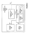
- FIG. 4 illustrates a block diagram of mobile communication device 420 as an example of mobile communication device 120 , as found in FIG. 1 , although mobile communication device 120 could use other configurations.
- Mobile communication device 420 in this example, includes communication interface 421 , processing system 423 , display system 427 , and location system 429 .
- Processing system 423 includes storage system 424 .
- Storage system 424 stores software 425 .
- Processing system 423 is communicatively linked to communication interface 421 by link 422 .
- Processing system 423 is communicatively linked to display system 427 by link 426 .
- Processing system 423 is communicatively linked to location system 429 by link 428 .
- Mobile communication device 420 may be distributed among multiple devices that together form elements 421 - 427 .
- Communication interface 421 comprises antennas, transceivers, circuitry, as well as other types of communication components—including combinations thereof.
- Processing system 423 retrieves and executes software 425 from storage system 424 .
- Processing system 423 could incorporate a computer microprocessor, logic circuit, or some other processing device, and may be distributed among multiple processing devices. In some examples, processing system 423 is located within the same equipment in which communication interface 421 , display system 427 , or location system 429 are located.
- Storage system 424 could include a computer-readable medium such as a disk, tape, buffer, cache, integrated circuit, server, or some other memory device, and also may be distributed among multiple memory devices.
- Software 425 may include an operating system, logs, utilities, drivers, networking software, and other software typically loaded onto a computer system. Software 425 could contain an application program, firmware, or some other form of computer-readable processing instructions. When executed by processing system 423 , software 425 directs processing system 423 to operate as described herein.
- Display system 427 includes circuitry and a viewscreen or user display used for viewing video content on mobile communication device 420 .
- display system 427 includes a viewscreen integrated into mobile communication device 420
- display system 427 may include an interface to a display system external to mobile communication device 420 .
- a speaker assembly or a headphone adapter is included for listening to audio content accompanying the video.
- Location system 429 includes equipment capable of determining a geographic location of mobile communication device 420 .
- location system 429 include a global-positioning system (GPS) receiver, a terrestrial position determining equipment (PDE) system, a triangulation-based location system, an emergency services location procedure system, or some other type of location determining system, including combinations thereof.
- GPS global-positioning system
- PDE terrestrial position determining equipment
- triangulation-based location system a triangulation-based location system
- emergency services location procedure system or some other type of location determining system, including combinations thereof.
- Other examples of location system 429 include merely an interface configured to communicate with external equipment capable of determining a geographic location of mobile communication device 420 , where location would then be received by location system 429 .
- location system 429 may be digital storage including the geographic location of mobile communication device 420 .
- Links 422 , 426 , and 428 comprise physical, logical, or virtual communication links, capable of communicating data, control signals, and communications, along with other information.
- links 422 , 426 , and 428 are encapsulated within the elements of communication interface 421 , processing system 423 , display system 427 , or location system 429 and may be a software or logical link.
- links 422 , 426 , and 428 use various communication media, such as air, space, metal, optical fiber, or some other signal propagation path—including combinations thereof.
- Links 422 , 426 , and 428 could be wired or wireless and use various protocols or communication formats as described herein for wireless link 112 —including combinations or variations thereof.
- Links 422 , 426 , and 428 could be a direct link or it might include various equipment, intermediate components, systems, and networks.
- Wireless link 412 could be similarly configured to that described for wireless link 112 or for links 422 , 426 , and 428 , although wireless link 412 could also use other configurations.
- FIG. 5 is a diagram illustrating a sequence of reference frames 501 and update frames 502 of video 503 .
- Video 503 is comprised of several frames, or time-correlated image elements of a video. These frames, when accumulated in a sequence, correspond to a portion of video 503 . In many examples of video 503 , several frames are used to comprise one portion, such as one second, of video 503 .
- the length of time of video 503 could be predetermined, as in the example of a fixed-length movie, or could be open-ended, as in the case of streaming newscast or sporting event which may continue indefinitely.
- reference frame types 501 and update frame types 502 comprise a portion of video 503 .
- Each reference frame 501 is typically a frame type used as a reference or key for an update frame 502 .
- Update frames 502 indicate a change, difference, or delta in the previous frame in a sequence of frames.
- reference frames 501 contain much more data than update frame 502 , and likewise require much more bandwidth to transfer.
- reference frames 501 precede a series of update frames 502 .
- Each update frame 502 indicates a change to the previous frame, whether the previous frame is a reference frame 501 or another update frame 502 .
- Several update frames 502 can follow a particular reference frame 501 , depending upon the video format used. In some example formats, each reference frame 501 occurs once for every 1 ⁇ 2 second of video 503 , with update frames 502 occurring when a reference frame 501 does not, to establish a total frame rate of 24 or 30 frames per second of video 503 . In other examples, more or less frames of each type could comprise each second of video 503 .
- Reference frames 501 include information relating to an entire visible frame of video, typically comprising enough data to complete an image or picture encompassing the entire viewable portion or scene of a video. This is in contrast to update frames 502 , which typically include only a subset of the information that encompasses the entire viewable portion of a video. As mentioned above, the update frames 502 indicate a change from a neighboring frame, where the neighboring frame could be either a reference frames 501 or update frames 502 . In this manner, each update frame 502 need only contain a smaller amount of data than a reference frame 501 . For example, a video containing a person walking past an unchanging or slowly changing background would typically require the update frames 502 to include information changing from one frame to the next (i.e. information relating to the motion of the person), whereas the reference frames 502 would typically include information encompassing the entire viewable portion of the video (i.e. information relating to the person and the background).
- reference frames 501 and update frames 502 can also contain sequencing information relating to a display order and a transmit order. However, a reference frame must be displayed first in order for subsequent update frames 502 to have a baseline or key from which a delta or change can be determined. In many examples, video 503 can be displayed in forward sequence or reverse sequence through a similar use of reference frames 501 and update frames 502 .
- reference frames 501 can include a frame type referred to as intra-frames (I frames), whereas update frames 502 can include several frame types referred to as predicted (P frames) or bidirectional frames (B frames).
- I frames intra-frames
- P frames predicted
- B frames bidirectional frames
- MPEG-1, MPEG-2, or MPEG-4 each incorporating similar principles as discussed herein.
- Other example video formats include QuickTime, DivX, VCEG, H.264, Windows Media Video (WMV), Ogg Theora, or other compressed video formats, which may follow similar frame utilization principles as found in MPEG.
- FIG. 6 is a system diagram illustrating communication system 600 .
- Communication system 600 includes mobile communication device 620 , wireless communication system 610 , and video system 650 .
- Mobile communication device 620 and wireless communication system 610 communicate over wireless link 630 .
- Video system 650 and wireless communication system 610 communicate over link 640 .
- Mobile communication device 620 comprises a smart phone capable of displaying video in this example.
- Wireless communication system 610 includes wireless communications network equipment capable of communicating with mobile communication device 620 .
- wireless communication system 610 includes base stations 611 - 612 and terrestrial position-determining equipment (PDE) system 615 .
- PDE terrestrial position-determining equipment
- a different number of mobile communication devices and base stations may be located in communication system 600 .
- Video system 650 includes equipment capable of transferring or streaming video to mobile communication device 620 . As shown in FIG. 6 , video system 650 comprises video server 651 , video controller 652 , media storage system 653 , and location database system 657 . Video server 651 and video controller 652 are communicatively linked by link 654 . Video server 651 and media storage system 653 are communicatively linked by link 655 . Video server 651 and location database system 657 are communicatively linked by link 656 . In some examples, video controller 652 , media storage system 653 , location database system 657 , or links 654 - 656 are located within the same equipment in which video server 651 is located.
- Video server 651 includes a data server for transferring video frames over wireless communication system 610 to mobile communication device 620 .
- Video controller 652 includes equipment for controlling the operations of video server 651 , and comprises a computer system.
- Media storage system 653 comprises a digital storage system for storing video frames and related content.
- media storage system 653 comprises a storage-area network (SAN) which stores a large collection of videos.
- Location database system 657 includes a database and a computer processing system including a digital storage medium, readable by a computer processing system, which stores the database thereon. The database includes information related to geographic areas associated with wireless communication system 610 .
- Links 654 - 656 comprise IP network links between video server 651 and video controller 652 , video server 651 and media storage system 653 , and video server 651 and location database system 657 , respectively.
- Link 640 comprises a T1 connection between video system 650 and wireless communication system 610 .
- Wireless link 630 uses the long-term evolution (LTE) protocol to exchange communications between mobile communication device 620 and wireless communication system 610 .
- LTE long-term evolution
- mobile communication device 620 can exchange communications with base station 611 or base station 612 , depending upon the location of mobile communication device 620 .
- wireless link 630 would link to base station 611
- wireless link 630 would link to base station 612 .
- This configuration is merely illustrative to show the capability of mobile communication device 620 to communicate with multiple base stations, with base station 612 being along a projected geographic path associated with mobile communication device 620 . This configuration is discussed further below regarding FIGS. 7 and 8 .
- Terrestrial position determining equipment (PDE) 615 includes equipment capable of determining a geographic location of mobile communication device 620 .
- Terrestrial PDE system could determine a position of mobile communication device 620 via a triangulation-based location, an emergency services location procedure, or by some other type of location determining method, including combinations thereof.
- FIG. 7 is a flow diagram that illustrates a method of operation of communication system 600 , as found in FIG. 6 . The phases shown in FIG. 7 are indicated herein parenthetically.
- video system 650 receives ( 701 ) a request for a video from mobile communications device 620 .
- Video server 651 requests ( 702 ) the video, as requested by mobile communication device 620 , from media storage system 653 .
- Media storage system 653 processes ( 703 ) the request for the video and begins to transfer the frames of the video to video server 651 over link 655 .
- Video system 650 determines ( 704 ) a projected geographic path of mobile communication device 620 .
- the projected geographic path of mobile communication device 620 is determined by monitoring a geographic location of the mobile communication device. Then, the geographic location is processed to determine if the geographic location is associated with a mobility pattern. A projected geographic path of the mobile communication device is then determined based on the mobility pattern. In this example, the mobility pattern is associated with road 803 , as shown in FIG. 8 . A further discussion of the determination of the projected geographic path based on the mobility pattern of mobile communication device 620 is found below and illustrated in FIG. 8 .
- location database system 657 could be queried with the geographic location. Location database system 657 could then transfer a response indicating if the geographic location is associated with a mobility pattern such as a road, land feature, or even past paths or trajectories followed by mobile communication device 620 .
- location database system 657 includes a database and a computer processing system which stores information related to geographic areas and mobility patterns associated with wireless communication system 610 and mobile communication device 620 . These geographic areas and mobility patterns could then correspond to geographic regions and paths which correspond to a certain bandwidth, signal strength, or other factors of wireless communications with mobile communication device 620 . In this example, the mobility patterns denote regions within wireless communication system 610 that support a certain bandwidth of wireless communications.
- video controller 652 requests the geographic location of mobile communication device 620 from terrestrial position-determining (PDE) system 615 in wireless communication system 610 . In other examples, video controller 652 requests this geographic location from base station 611 . In examples where more than one base station is located within wireless communication system 610 , video controller 652 must first determine from which base station to request the geographic location. Video controller 652 could query another system in wireless communication system 610 to obtain an indicator as to which base station has information related to the geographic location of mobile communication device 620 .
- PDE position-determining
- Video system 650 also determines ( 705 ) a transfer schedule for reference frames of a video based on the projected geographic path of mobile communication device 620 .
- the transfer schedule indicates where along the projected geographic path the reference frames should be transferred and withheld to mobile communication device 620 .
- a further discussion of the determination of the transfer schedule is found below and illustrated in FIG. 8 .
- the reference frames are then transferred ( 706 ) based on the transfer schedule to mobile communication device 620 over wireless communication system 610 .
- Video system 650 concurrently, and without regard to the projected geographic path of mobile communication device 620 , transfers ( 707 ) update frames of the video to mobile communication device 620 .
- mobile communication device 620 receives the reference frames of the video when transferred by video system 650 .
- Mobile communication device 620 also receives the update frames of the video transferred from video system 650 .
- Mobile communication device 620 displays both the reference frames and the update frames. Since the reference frames may be received in a different sequence with respect to the update frames, mobile communication device 620 may need to process the reference frames and the update frames and determine a playback sequence.
- mobile communication device 620 stores the update frames in a buffer or cache while awaiting reference frames. As the reference frames are received, the update frames can then be transferred from the buffer and displayed in the correct sequence with the reference frames.
- An example of the relationship between reference frames and update frames is illustrated in FIG. 5 .
- a projected geographic path of mobile communication device 620 will vary depending upon many factors, including the intentions of the operator of video system 650 , the quality of video desired to be transferred, the availability of geographic location information, the SLA of the user of mobile communication device 620 , the motion or path of mobile communication device 620 , a deviation of mobile communication device 620 from a previously projected geographic path, among other factors.
- FIG. 8 is a diagram illustrating an overhead representation of communication system 600 , as found in FIG. 6 .
- FIG. 8 includes mobile communication device (MCD) 620 and base stations 611 - 612 , both also found in FIG. 6 .
- Wireless communication system 610 , video system 650 , wireless link 630 , and link 640 are not shown in FIG. 8 for clarity.
- base stations 611 - 612 and MCD 620 can exchange wireless communications.
- Base stations 611 - 612 have a limited geographic range over which they can support a certain quality of communications with mobile communication devices.
- the limited range over which base station 611 can support a certain quality of communications with MCD 620 is indicated by coverage area 801 and the limited range over which base station 612 can support a certain quality of communications with MCD 620 is indicated by coverage area 802 .
- this limited range could be a function of the signal strength of base stations 611 - 612 or MCD 620 , determined by the operator of wireless communication system 610 or video system 650 , a function of the geographic location of base stations 611 - 612 or MCD 620 , a limitation of the communication protocol employed, or some other factor.
- the limited range could be defined by a region beyond which mobile communication devices must transmit with a high signal energy level to establish effective communications with base stations 611 - 612 , where such a high signal energy level is determined to cause too much interference with a neighboring base station or other mobile communication devices in communication system 600 .
- FIG. 8 shows two geographic locations of MCD 620 .
- First geographic location 810 A represents an initial geographic location of MCD 620 .
- Projected geographic location 810 P represents a second geographic location of MCD 620 , after MCD 620 traverses road 803 .
- MCD 620 is within coverage area 801 when at first geographic location 810 A.
- MCD 620 is within coverage area 802 when at projected geographic location 810 P.
- wireless communications between MCD 520 and the respective base station could, for example, occur at a lower bandwidth, whereas when in coverage area 801 or coverage area 802 , wireless communications between MCD 620 and the respective base station could, for example, occur at a high bandwidth.
- a mobility pattern could be determined by processing first geographic location 810 A and determining that the location is associated with road 803 .
- the projected path of MCD 620 would then be determined to be localized to road 803 , and consequently MCD 620 would leave coverage area 801 , travel distance 810 D, and encounter coverage area 802 to arrive at projected geographic location 810 P.
- databases such as location database system 657 , or processing could be used to determine the existence and location of road 803 .
- more than one geographic location of MCD 620 could be determined in order to determine a direction and speed—aiding in the estimation of the transit time through the coverage areas on road 803 .
- a transfer schedule would be determined.
- the transfer schedule would incorporate the information associated with the mobility pattern to indicate when MCD 620 would be located in the various regions along road 803 , including coverage area 801 , distance 810 D, and coverage area 802 .
- the transfer schedule would also indicate when video system 650 should transfer and withhold reference frames to MCD 620 .
- the reference frames would be transferred while MCD 620 was located in coverage area 801 , in anticipation of transit through distance 810 D between coverage areas.
- enough reference frames would need to be transferred to and buffered in MCD 620 while in coverage area 801 .
- MCD 620 transits distance 810 D and reference frames are withheld from transfer, enough reference frames are buffered in MCD 620 for playback until more reference frames could be transferred once MCD 620 reaches coverage area 802 , as projected.
- FIG. 8 Although hexagonal regions, as defined by base station coverage areas 801 - 802 , are shown in FIG. 8 , it should be understood that the geographic regions could be of other configurations or of a different quantity, as determined by geographic features, empirical data, the desires of the operators of wireless communication system 610 or video system 650 , or by other factors, including combinations thereof.
- coverage area 802 is of a similar size and shape as coverage are 801 , but coverage area 802 spills off the page in FIG. 8 to illustrate distance 810 D between coverage area 801 and coverage area 802 .
- FIG. 9 is a system diagram illustrating communication system 900 .
- Communication system 900 includes mobile communication device 920 , wireless communication system 910 , video system 950 , live video production system 953 , and Internet 990 .
- Mobile communication device 920 and wireless communication system 910 communicate over wireless link 930 .
- Video system 950 and wireless communication system 910 communicate through Internet 990 over links 980 and 940 .
- Wireless link 930 includes logical transport links 931 - 932 .
- Link 940 includes logical transport links 941 - 942 .
- Link 980 includes logical transport links 981 - 982 .
- Mobile communication device 920 comprises a wireless-enabled laptop computer capable of displaying video in this example.
- Mobile communication device 920 includes global-positioning system (GPS) receiver 921 .
- GPS receiver 921 includes circuitry, processors, or equipment capable of determining a geographic location of mobile communication device 920 .
- Wireless communication system 910 includes wireless communications network equipment capable of communicating with mobile communication device 920 . As shown in FIG. 9 , wireless communication system 910 includes boomer cell 913 .
- a boomer cell is an example of a base station tailored to service a high number of mobile communication devices over a large geographic area, such as a metropolitan area. In other examples, a different number of mobile communication devices and base stations may be located in communication system 900 .
- Video system 950 includes equipment capable of transferring or streaming video to mobile communication device 920 . As shown in FIG. 9 , video system 950 includes streaming video server 951 . Streaming video server 951 includes a data server and routing equipment for transferring streaming video over Internet 990 and wireless communication system 910 to mobile communication device 920 .
- Live video production system 953 includes equipment associated with capturing, digitizing, compressing, and transferring live video from events such as sporting events or on-site news coverage.
- Streaming video server 951 and live video production system 953 are communicatively linked by link 955 .
- Link 955 comprises an IP network link between streaming video server 951 and live video production system 953 .
- Links 940 and 980 comprise high-speed optical connections between video system 950 , Internet 990 , and wireless communication system 910 .
- Wireless link 930 uses worldwide interoperability for microwave access (WiMAX) to exchange communications between mobile communication device 920 and wireless communication system 910 .
- WiMAX worldwide interoperability for microwave access
- Wireless link 930 , link 940 , and link 980 may comprise many different signals sharing the same link. As shown in FIG. 9 , wireless link 930 , link 940 , and link 980 include several logical transport links. Wireless link 930 includes logical transport links 931 - 932 . Link 940 includes logical transport links 941 - 942 . Link 980 includes logical transport links 981 - 982 . In this example, these logical transport links represent different IP socket pathways between the associated equipment.
- FIG. 10 is a flow diagram that illustrates a method of operation of communication system 900 , as found in FIG. 9 .
- the phases shown in FIG. 10 are indicated herein parenthetically.
- video system 950 receives ( 1001 ) a request for live video from mobile communications device 920 .
- Streaming video server 951 then requests ( 1002 ) the live video, as requested by mobile communication device 620 , from live video production system 953 .
- Live video production system 953 processes ( 1003 ) the request for the video and begins to stream the frames of the video to streaming video server 951 over link 955 .
- Live video production system 953 could include, in this example, equipment associated with capturing, digitizing, compressing, and transferring live video. However, in other examples, live video production system 953 transfers uncompressed and possibly analog video to streaming video server 951 .
- Streaming video server 951 could be configured to digitize and/or compress the video for transport to mobile communication device 920 .
- the video may be digitized and compressed prior to arrival in streaming video server 951 , the video may undergo a format, compression, or encoding change in streaming video server 951 to place the video in a format compatible for decoding on mobile communication device 920 .
- Video system 950 determines ( 1004 ) a projected geographic path of mobile communication device 920 .
- the projected geographic path of mobile communication device 920 is determined by monitoring a first geographic location of mobile communication device 920 and monitoring a second geographic location of mobile communication device 920 . Then, the first geographic location and the second geographic location are processed to determine a traveled path between the first geographic location and the second geographic location. The traveled path is extrapolated to determine the projected geographic path.
- FIG. 11 A further discussion of the determination of the projected geographic path based on the traveled path of mobile communication device 920 is found below and illustrated in FIG. 11 .
- video system 950 requests the geographic locations from mobile communication device 920 .
- mobile communication device 920 provides an initial geographic location with the request for video, and subsequent geographic locations at a later time.
- Mobile communication device 920 includes global-positioning system (GPS) receiver 921 in this example, which determines the geographic location of mobile communication device 920 .
- GPS global-positioning system
- Video system 950 also determines ( 1005 ) a transfer schedule for reference frames of a video based on the projected geographic path of mobile communication device 920 .
- the transfer schedule indicates where along the projected geographic path the reference frames should be transferred to mobile communication device 920 .
- a further discussion of the determination of the transfer schedule is found below and illustrated in FIG. 11 .
- Streaming video server 951 transfers the reference frames ( 1006 ) based on the transfer schedule to mobile communication device 920 over wireless communication system 910 .
- the reference frames could be transferred over logical transport link 981 between streaming video server 951 and Internet 990 , over logical transport link 941 between Internet 990 and boomer cell 913 , and over logical transport link 931 between boomer cell 913 and mobile communication device 920 .
- Streaming video server 951 concurrently, and without regard to the projected geographic path of mobile communication device 920 , transfers ( 1008 ) update frames of the video to mobile communication device 920 .
- the update frames could be transferred over logical transport link 982 between streaming video server 951 and Internet 990 , over logical transport link 942 between Internet 990 and boomer cell 913 , and over logical transport link 932 between boomer cell 913 and mobile communication device 920 .
- Mobile communication device 920 receives ( 1007 ) the reference frames of the video when transferred by streaming video server 951 .
- Mobile communication device 920 also receives ( 1009 ) the update frames of the video transferred from streaming video server 951 . Since the reference frames may be received in a different sequence with respect to the update frames, mobile communication device 920 may need to process the reference frames and the update frames and determine ( 1010 ) a playback sequence. In some examples, mobile communication device 920 stores some of the frames in a buffer or cache while awaiting other frames. As the various frames are received, the frames can then be transferred from the buffer and displayed ( 1011 ) in the correct sequence. The relationship between reference frames and update frames is illustrated in FIG. 5 , as discussed above.
- mobile communication device 920 monitors a playback quality of the video and transfers an indicator of the playback quality to streaming video server 951 .
- Streaming video server 951 could then transfer this indication of playback quality to possibly a location database system along with the geographic location of mobile communication device 920 .
- a location database system could be configured to create a database of geographic regions of different playback quality.
- involvement of wireless communication system 910 would not be needed for the operator of video system 950 to create a database, or even a map, indicating which geographic locations within wireless communication system 910 correspond to high quality video playback.
- the database could be predetermined based upon information from the operator of wireless communication system 910 and the indicator of playback quality could be used to update or refine the database in the location database system.
- a projected geographic path of mobile communication device 920 will vary depending upon many factors, including the intentions of the operator of video system 950 , the quality of video desired to be transferred, the availability of geographic location information, the SLA of the user of mobile communication device 920 , the motion or path of mobile communication device 920 , among other factors.
- FIG. 11 is a diagram illustrating an overhead representation of communication system 900 , as found in FIG. 9 .
- FIG. 11 includes mobile communication device (MCD) 920 and boomer cell 913 , both also found in FIG. 9 .
- Wireless communication system 910 , video system 950 , wireless link 930 , Internet 990 , live video production system 953 , and links 940 , 955 , and 980 are not shown in FIG. 11 for clarity.
- MCD 920 and boomer cell 913 can exchange wireless communications.
- Boomer cell 913 has a limited geographic range over which it can support communications with MCD 920 .
- the limited range over which boomer cell 913 can support communications with mobile communication devices is indicated by coverage area 1100 .
- the limited range is a function of the limitations of the WiMAX communication protocol employed.
- FIG. 11 also shows three geographic locations of MCD 920 .
- First geographic location 1101 A represents an initial geographic location of MCD 920 .
- Second geographic location 1101 B represents a subsequent geographic location of MCD 920 after traversing a geographic distance, denoted by traveled path 1102 T.
- Projected geographic location 1101 P represents a third geographic location of MCD 920 , after MCD 920 traverses projected path 1102 P.
- MCD 920 is within coverage area 1101 at all three geographic location in this example. However, for a portion of projected path 1102 P, MCD 920 passes through dead zone 1101 Z, as defined by distance 1101 D along projected path 1102 P.
- Dead zone 1101 Z represents a region within coverage area 1100 capable of low quality wireless communications between MCD 920 and boomer cell 913 .
- the bandwidth or signal strength of wireless communications are lower inside dead zone 1101 Z, while in other examples, wireless communications are entirely difficult or non-existent within dead zone 1101 Z.
- wireless communications between MCD 920 and boomer cell 913 could, for example, occur at a low bandwidth, whereas when outside dead zone 1101 Z (but still within coverage area 1100 ), wireless communications between MCD 920 and boomer cell 913 , for example, occur at a high bandwidth.
- Further systems, databases, or processing could be used to determine the existence and location of dead zone 1101 Z.
- a transfer schedule would be determined.
- the transfer schedule would incorporate the information associated with projected path 1102 P to indicate when MCD 920 would be located in the various regions along projected path 1102 P; these regions include coverage area 1100 and dead zone 1101 Z.
- the transfer schedule would also indicate when video system 950 should transfer and withhold reference frames of the video to MCD 920 .
- video system 950 would determine that MCD 920 would be in a region of high bandwidth along projected path before progressing into a region of low bandwidth (dead zone 1101 Z).
- the reference frames could then be scheduled to be burst to MCD 920 in a manner more rapid than normal, and possibly out of sequence with the update frames, before MCD 920 is expected to arrive in dead zone 1101 Z.
- MCD 920 could then buffer or cache the reference frames. Then, when MCD 920 arrives in dead zone 1101 Z, the lower bandwidth in dead zone 1101 Z—which may not allow for effective transfer of the generally larger reference frames—could be compensated for in an efficient manner.
- the reference frames would not be scheduled for transfer to MCD 920 for distance 1101 D along projected path 1102 P. However, the generally smaller update frames would be transferred to MCD 920 without regard to dead zone 1101 Z.
- efficient use of the limited bandwidth along distance 1101 D of projected path 1102 P is achieved while still maintaining a consistent transfer of video frames to MCD 920 .
- the transfer of the reference frames could resume or be burst as described above in anticipation for further dead zones or for a path beyond coverage area 1100 .
- FIG. 11 Although a hexagonal region, as defined by boomer cell coverage area 1100 , and a generally circular dead zone 1101 Z, are shown in FIG. 11 , it should be understood that the geographic regions could be of other configurations or of a different quantity, as determined by geographic features, empirical data, the desires of the operators of wireless communication system 910 or video system 950 , or by other factors, including combinations thereof.
- a video system configured as described herein can provide a higher quality of video service and possibly better user experience over wireless links where the quality of wireless communications can vary when a mobile communication device transits across geographic locations. Since, in many of the examples included herein, reference frames are transferred separately from update frames, and the reference frames are only transferred when the quality of the wireless link between a mobile communication device and a wireless communication system can support, for example a certain bandwidth, a mobile communication device can buffer up the generally smaller update frames separately from the generally larger reference frames. When the quality of the wireless link, as defined by geographic location, allows for transfer of the reference frames, the video server can then transfer these generally larger reference frames, making efficient use of the resources of the wireless link.
- a transfer schedule is determined which allows for a burst transfer of reference frames while a mobile communication device is in a region of high quality wireless coverage, while withholding the transfer of reference frames while the mobile communication device is in a region of low quality wireless coverage.
- the a burst of the reference frames will transfer according to the transfer schedule and remain buffered in the mobile communication device until needed, while the generally smaller bandwidth—and more frequent—update frames are always transferred.
- many more update frames are required than reference frames for each second of video.
- a method of operation described herein could allow a mobile communication device traveling through areas of various quality of wireless coverage to weather periods of poor wireless quality while still maintaining a high-quality of video performance.
- a compressed video can be transferred from a video server to a mobile communication device over a wireless communication system in a more efficient manner resulting in a better user experience and possibly higher or more consistent frame transfer and/or playback rates of the video.
- the video transferred from a video server could comprise a different format, encoding scheme, or resolution, among other changes.
- a video server could possibly request this different video format from a media storage system in some examples.
- a different and possibly more lossy video compression scheme could be used in regions of lower quality wireless communication to achieve a similar effect.
- FIGS. 1-11 and the previous descriptions depict specific embodiments to teach those skilled in the art how to make and use the best mode. For the purpose of teaching inventive principles, some conventional aspects have been simplified or omitted. Those skilled in the art will appreciate variations from these embodiments that fall within the scope of the invention. Those skilled in the art will also appreciate that the features described above can be combined in various ways to form multiple embodiments. As a result, the invention is not limited to the specific embodiments described above, but only by the claims and their equivalents.
Abstract
Description
Claims (25)
Priority Applications (1)
| Application Number | Priority Date | Filing Date | Title |
|---|---|---|---|
| US12/255,930 US8239911B1 (en) | 2008-10-22 | 2008-10-22 | Video bursting based upon mobile device path |
Applications Claiming Priority (1)
| Application Number | Priority Date | Filing Date | Title |
|---|---|---|---|
| US12/255,930 US8239911B1 (en) | 2008-10-22 | 2008-10-22 | Video bursting based upon mobile device path |
Publications (1)
| Publication Number | Publication Date |
|---|---|
| US8239911B1 true US8239911B1 (en) | 2012-08-07 |
Family
ID=46583385
Family Applications (1)
| Application Number | Title | Priority Date | Filing Date |
|---|---|---|---|
| US12/255,930 Active 2030-09-14 US8239911B1 (en) | 2008-10-22 | 2008-10-22 | Video bursting based upon mobile device path |
Country Status (1)
| Country | Link |
|---|---|
| US (1) | US8239911B1 (en) |
Cited By (10)
| Publication number | Priority date | Publication date | Assignee | Title |
|---|---|---|---|---|
| US20140250468A1 (en) * | 2011-10-04 | 2014-09-04 | International Business Machines Corporation | Pre-emptive content caching in mobile networks |
| US20150149591A1 (en) * | 2013-11-27 | 2015-05-28 | At&T Intellectual Property I, Lp | Client-side location aware network selection |
| US20150149592A1 (en) * | 2013-11-27 | 2015-05-28 | At&T Intellectual Property I, Lp | Server-side scheduling for media transmissions according to client device states |
| US20150146697A1 (en) * | 2013-11-27 | 2015-05-28 | At&T Intellectual Property I, Lp | Client-side scheduling for media transmissions according to client device states |
| US20150149590A1 (en) * | 2013-11-27 | 2015-05-28 | At&T Intellectual Property I, Lp | Server-side scheduling for media transmissions |
| US20160344790A1 (en) * | 2015-05-20 | 2016-11-24 | Fujitsu Limited | Wireless communication device and wireless communication method |
| US11122329B2 (en) * | 2016-02-25 | 2021-09-14 | Telefonaktiebolaget Lm Ericsson (Publ) | Predicting multimedia session MOS |
| US11165522B2 (en) * | 2017-10-12 | 2021-11-02 | Intel Corporation | Radio link quality prediction |
| US11316944B2 (en) * | 2018-05-02 | 2022-04-26 | Spotify Ab | Predictive caching |
| US11412052B2 (en) * | 2018-12-28 | 2022-08-09 | Intel Corporation | Quality of service (QoS) management in edge computing environments |
Citations (3)
| Publication number | Priority date | Publication date | Assignee | Title |
|---|---|---|---|---|
| US5508754A (en) * | 1994-03-22 | 1996-04-16 | National Captioning Institute | System for encoding and displaying captions for television programs |
| US7006881B1 (en) * | 1991-12-23 | 2006-02-28 | Steven Hoffberg | Media recording device with remote graphic user interface |
| US20070005795A1 (en) * | 1999-10-22 | 2007-01-04 | Activesky, Inc. | Object oriented video system |
-
2008
- 2008-10-22 US US12/255,930 patent/US8239911B1/en active Active
Patent Citations (3)
| Publication number | Priority date | Publication date | Assignee | Title |
|---|---|---|---|---|
| US7006881B1 (en) * | 1991-12-23 | 2006-02-28 | Steven Hoffberg | Media recording device with remote graphic user interface |
| US5508754A (en) * | 1994-03-22 | 1996-04-16 | National Captioning Institute | System for encoding and displaying captions for television programs |
| US20070005795A1 (en) * | 1999-10-22 | 2007-01-04 | Activesky, Inc. | Object oriented video system |
Cited By (33)
| Publication number | Priority date | Publication date | Assignee | Title |
|---|---|---|---|---|
| US20140250468A1 (en) * | 2011-10-04 | 2014-09-04 | International Business Machines Corporation | Pre-emptive content caching in mobile networks |
| US10341693B2 (en) * | 2011-10-04 | 2019-07-02 | International Business Machines Corporation | Pre-emptive content caching in mobile networks |
| US20180317117A1 (en) * | 2013-11-27 | 2018-11-01 | At&T Intellectual Property I, L.P. | Client-side scheduling for media transmissions according to client device states |
| US10827032B2 (en) * | 2013-11-27 | 2020-11-03 | At&T Intellectual Property I, L.P. | Server-side scheduling for media transmissions according to client device states |
| US20150149592A1 (en) * | 2013-11-27 | 2015-05-28 | At&T Intellectual Property I, Lp | Server-side scheduling for media transmissions according to client device states |
| US9197717B2 (en) * | 2013-11-27 | 2015-11-24 | At&T Intellectual Property I, Lp | Server-side scheduling for media transmissions according to client device states |
| US20160044133A1 (en) * | 2013-11-27 | 2016-02-11 | At&T Intellectual Property I, Lp | Server-side scheduling for media transmissions according to client device states |
| US9363333B2 (en) * | 2013-11-27 | 2016-06-07 | At&T Intellectual Property I, Lp | Server-side scheduling for media transmissions |
| US9432478B2 (en) * | 2013-11-27 | 2016-08-30 | At&T Intellectual Property I, L.P. | Client-side location aware network selection |
| US20160255172A1 (en) * | 2013-11-27 | 2016-09-01 | At&T Intellectual Property I, Lp | Server-side scheduling for media transmissions |
| US20160345240A1 (en) * | 2013-11-27 | 2016-11-24 | At&T Intellectual Property I, L.P. | Client-side location aware network selection |
| US20180332139A1 (en) * | 2013-11-27 | 2018-11-15 | At&T Intellectual Property I, L.P. | Server-side scheduling for media transmissions |
| US9629104B2 (en) * | 2013-11-27 | 2017-04-18 | At&T Intellectual Property I, Lp | Client-side scheduling for media transmissions according to client device states |
| US9769284B2 (en) * | 2013-11-27 | 2017-09-19 | At&T Intellectual Property I, L.P. | Server-side scheduling for media transmissions according to client device states |
| US10045246B2 (en) | 2013-11-27 | 2018-08-07 | At&T Intellectual Property I, L.P. | Client-side scheduling for media transmissions according to client device states |
| US10063656B2 (en) * | 2013-11-27 | 2018-08-28 | At&T Intellectual Property I, L.P. | Server-side scheduling for media transmissions |
| US20150149590A1 (en) * | 2013-11-27 | 2015-05-28 | At&T Intellectual Property I, Lp | Server-side scheduling for media transmissions |
| US11412440B2 (en) * | 2013-11-27 | 2022-08-09 | At&T Intellectual Property I, L.P. | Client-side location aware network selection |
| US20150146697A1 (en) * | 2013-11-27 | 2015-05-28 | At&T Intellectual Property I, Lp | Client-side scheduling for media transmissions according to client device states |
| US20150149591A1 (en) * | 2013-11-27 | 2015-05-28 | At&T Intellectual Property I, Lp | Client-side location aware network selection |
| US10356208B2 (en) * | 2013-11-27 | 2019-07-16 | At&T Intellectual Property I, L.P. | Server-side scheduling for media transmissions according to client device states |
| US10516757B2 (en) * | 2013-11-27 | 2019-12-24 | At&T Intellectual Property I, L.P. | Server-side scheduling for media transmissions |
| US10524190B2 (en) * | 2013-11-27 | 2019-12-31 | At&T Intellectual Property I, L.P. | Client-side location aware network selection |
| US10728790B2 (en) | 2013-11-27 | 2020-07-28 | At&T Intellectual Property I, L.P. | Client-side scheduling for media transmissions according to client device states |
| US10136380B2 (en) * | 2013-11-27 | 2018-11-20 | At&T Intellectual Property I, L.P. | Client-side location aware network selection |
| US10972961B2 (en) * | 2013-11-27 | 2021-04-06 | At&T Intellectual Property I, L.P. | Client-side location aware network selection |
| US20160344790A1 (en) * | 2015-05-20 | 2016-11-24 | Fujitsu Limited | Wireless communication device and wireless communication method |
| US11122329B2 (en) * | 2016-02-25 | 2021-09-14 | Telefonaktiebolaget Lm Ericsson (Publ) | Predicting multimedia session MOS |
| US11165522B2 (en) * | 2017-10-12 | 2021-11-02 | Intel Corporation | Radio link quality prediction |
| US11876571B2 (en) | 2017-10-12 | 2024-01-16 | Intel Corporation | Radio link quality prediction |
| US11316944B2 (en) * | 2018-05-02 | 2022-04-26 | Spotify Ab | Predictive caching |
| US20220210242A1 (en) * | 2018-05-02 | 2022-06-30 | Spotify Ab | Predictive caching |
| US11412052B2 (en) * | 2018-12-28 | 2022-08-09 | Intel Corporation | Quality of service (QoS) management in edge computing environments |
Similar Documents
| Publication | Publication Date | Title |
|---|---|---|
| US8239911B1 (en) | Video bursting based upon mobile device path | |
| US8254441B2 (en) | Video streaming based upon wireless quality | |
| US8942215B2 (en) | System and method for transmission of data from a wireless mobile device over a multipath wireless router | |
| US11627354B2 (en) | Synchronizing the storing of streaming video | |
| KR101900168B1 (en) | Adaptive media streaming | |
| US9042444B2 (en) | System and method for transmission of data signals over a wireless network | |
| US20200204484A1 (en) | Device, system, and method of pre-processing and data delivery for multi-link communications and for media content | |
| US20120314127A1 (en) | Provisioning network resources responsive to video requirements of user equipment nodes | |
| US8737803B2 (en) | Method and apparatus for storing and streaming audiovisual content | |
| US20190387426A1 (en) | Method for providing streaming service and apparatus therefor | |
| US20120303797A1 (en) | Scalable audiovisual streaming method and apparatus | |
| US11490231B2 (en) | V2X congestion-sensitive preemptive data download request | |
| US20120304240A1 (en) | Method and apparatus for selecting audiovisual content for streaming | |
| US8239900B1 (en) | Video bursting based upon wireless device location | |
| EP2716039A2 (en) | Scalable audiovisual streaming method and apparatus | |
| US10999625B2 (en) | Method for reporting QoS/QoE in mobile environment and device therefor | |
| WO2010110066A1 (en) | Content distribution system, content distribution server, content distribution method, and program | |
| Riiser | Adaptive bitrate video streaming over HTTP in mobile wireless networks | |
| JP2005006131A (en) | Appropriate band setting data transmitting mobile terminal, appropriate band setting device, and appropriate band setting transmission and reception system | |
| US20160373509A1 (en) | APPARATUS AND METHOD FOR REPORTING QoS/QoE IN MOBILE ENVIRONMENT | |
| Lopes et al. | Real-time video frame differentiation in multihomed VANETs | |
| CN109416822B (en) | Method for reporting QOS/QOE in mobile environment and apparatus therefor | |
| JP6271072B1 (en) | Terminal device, video distribution system, and video distribution method | |
| JP6247782B1 (en) | Terminal device, video distribution system, and video distribution method | |
| Tamizhselvi et al. | An Advanced Efficient Video Streaming Framework for Vehicular Adhoc Networks Using VANET Streaming Protocol |
Legal Events
| Date | Code | Title | Description |
|---|---|---|---|
| AS | Assignment |
Owner name: SPRINT WIRELESS BROADBAND COMPANY LLC, KANSAS Free format text: ASSIGNMENT OF ASSIGNORS INTEREST;ASSIGNOR:SUN, YAOJUN;REEL/FRAME:021720/0324 Effective date: 20081006 |
|
| AS | Assignment |
Owner name: CLEAR WIRELESS LLC, WASHINGTON Free format text: ASSIGNMENT OF ASSIGNORS INTEREST;ASSIGNOR:SPRINT WIRELESS BROADBAND COMPANY LLC;REEL/FRAME:022184/0875 Effective date: 20090129 |
|
| AS | Assignment |
Owner name: MORGAN STANLEY & CO., INC., AS COLLATERAL AGENT, N Free format text: SECURITY AGREEMENT;ASSIGNOR:CLEAR WIRELESS LLC;REEL/FRAME:022815/0429 Effective date: 20090608 |
|
| AS | Assignment |
Owner name: CLEAR WIRELESS LLC, WASHINGTON Free format text: TERMINATION AND RELEASE OF SECURITY INTEREST IN PATENT RIGHTS;ASSIGNOR:MORGAN STANLEY & CO., INC., AS COLLATERAL AGENT;REEL/FRAME:023567/0236 Effective date: 20091124 |
|
| AS | Assignment |
Owner name: WILMINGTON TRUST FSB, AS COLLATERAL AGENT, MINNESO Free format text: SECURITY AGREEMENT;ASSIGNORS:CLEARWIRE LEGACY LLC;CLEAR WIRELESS LLC;REEL/FRAME:023574/0539 Effective date: 20091124 |
|
| AS | Assignment |
Owner name: CLEARWIRE IP HOLDINGS LLC, WASHINGTON Free format text: ASSIGNMENT OF ASSIGNORS INTEREST;ASSIGNOR:CLEARWIRE COMMUNICATIONS LLC;REEL/FRAME:027134/0855 Effective date: 20111026 Owner name: CLEARWIRE COMMUNICATIONS LLC, WASHINGTON Free format text: ASSIGNMENT OF ASSIGNORS INTEREST;ASSIGNOR:CLEAR WIRELESS LLC;REEL/FRAME:027134/0837 Effective date: 20111026 |
|
| STCF | Information on status: patent grant |
Free format text: PATENTED CASE |
|
| FPAY | Fee payment |
Year of fee payment: 4 |
|
| AS | Assignment |
Owner name: DEUTSCHE BANK TRUST COMPANY AMERICAS, NEW YORK Free format text: GRANT OF FIRST PRIORITY AND JUNIOR PRIORITY SECURITY INTEREST IN PATENT RIGHTS;ASSIGNOR:CLEARWIRE IP HOLDINGS LLC;REEL/FRAME:041882/0875 Effective date: 20170203 |
|
| MAFP | Maintenance fee payment |
Free format text: PAYMENT OF MAINTENANCE FEE, 8TH YEAR, LARGE ENTITY (ORIGINAL EVENT CODE: M1552); ENTITY STATUS OF PATENT OWNER: LARGE ENTITY Year of fee payment: 8 |
|
| AS | Assignment |
Owner name: CLEARWIRE IP HOLDINGS LLC, KANSAS Free format text: TERMINATION AND RELEASE OF FIRST PRIORITY AND JUNIOR PRIORITY SECURITY INTEREST IN PATENT RIGHTS;ASSIGNOR:DEUTSCHE BANK TRUST COMPANY AMERICAS;REEL/FRAME:052291/0439 Effective date: 20200401 |
|
| AS | Assignment |
Owner name: DEUTSCHE BANK TRUST COMPANY AMERICAS, NEW YORK Free format text: SECURITY AGREEMENT;ASSIGNORS:T-MOBILE USA, INC.;ISBV LLC;T-MOBILE CENTRAL LLC;AND OTHERS;REEL/FRAME:053182/0001 Effective date: 20200401 |
|
| AS | Assignment |
Owner name: CLEAR WIRELESS LLC, KANSAS Free format text: TERMINATION AND RELEASE OF SECURITY INTEREST IN PATENTS;ASSIGNOR:WILMINGTON TRUST, NATIONAL ASSOCIATION, AS SUCCESSOR BY MERGER TO WILMINGTON TRUST FSB;REEL/FRAME:053182/0700 Effective date: 20200331 Owner name: CLEARWIRE LEGACY LLC, KANSAS Free format text: TERMINATION AND RELEASE OF SECURITY INTEREST IN PATENTS;ASSIGNOR:WILMINGTON TRUST, NATIONAL ASSOCIATION, AS SUCCESSOR BY MERGER TO WILMINGTON TRUST FSB;REEL/FRAME:053182/0700 Effective date: 20200331 |
|
| AS | Assignment |
Owner name: SPRINT SPECTRUM LLC, KANSAS Free format text: RELEASE BY SECURED PARTY;ASSIGNOR:DEUTSCHE BANK TRUST COMPANY AMERICAS;REEL/FRAME:062595/0001 Effective date: 20220822 Owner name: SPRINT INTERNATIONAL INCORPORATED, KANSAS Free format text: RELEASE BY SECURED PARTY;ASSIGNOR:DEUTSCHE BANK TRUST COMPANY AMERICAS;REEL/FRAME:062595/0001 Effective date: 20220822 Owner name: SPRINT COMMUNICATIONS COMPANY L.P., KANSAS Free format text: RELEASE BY SECURED PARTY;ASSIGNOR:DEUTSCHE BANK TRUST COMPANY AMERICAS;REEL/FRAME:062595/0001 Effective date: 20220822 Owner name: SPRINTCOM LLC, KANSAS Free format text: RELEASE BY SECURED PARTY;ASSIGNOR:DEUTSCHE BANK TRUST COMPANY AMERICAS;REEL/FRAME:062595/0001 Effective date: 20220822 Owner name: CLEARWIRE IP HOLDINGS LLC, KANSAS Free format text: RELEASE BY SECURED PARTY;ASSIGNOR:DEUTSCHE BANK TRUST COMPANY AMERICAS;REEL/FRAME:062595/0001 Effective date: 20220822 Owner name: CLEARWIRE COMMUNICATIONS LLC, KANSAS Free format text: RELEASE BY SECURED PARTY;ASSIGNOR:DEUTSCHE BANK TRUST COMPANY AMERICAS;REEL/FRAME:062595/0001 Effective date: 20220822 Owner name: BOOST WORLDWIDE, LLC, KANSAS Free format text: RELEASE BY SECURED PARTY;ASSIGNOR:DEUTSCHE BANK TRUST COMPANY AMERICAS;REEL/FRAME:062595/0001 Effective date: 20220822 Owner name: ASSURANCE WIRELESS USA, L.P., KANSAS Free format text: RELEASE BY SECURED PARTY;ASSIGNOR:DEUTSCHE BANK TRUST COMPANY AMERICAS;REEL/FRAME:062595/0001 Effective date: 20220822 Owner name: T-MOBILE USA, INC., WASHINGTON Free format text: RELEASE BY SECURED PARTY;ASSIGNOR:DEUTSCHE BANK TRUST COMPANY AMERICAS;REEL/FRAME:062595/0001 Effective date: 20220822 Owner name: T-MOBILE CENTRAL LLC, WASHINGTON Free format text: RELEASE BY SECURED PARTY;ASSIGNOR:DEUTSCHE BANK TRUST COMPANY AMERICAS;REEL/FRAME:062595/0001 Effective date: 20220822 Owner name: PUSHSPRING, LLC, WASHINGTON Free format text: RELEASE BY SECURED PARTY;ASSIGNOR:DEUTSCHE BANK TRUST COMPANY AMERICAS;REEL/FRAME:062595/0001 Effective date: 20220822 Owner name: LAYER3 TV, LLC, WASHINGTON Free format text: RELEASE BY SECURED PARTY;ASSIGNOR:DEUTSCHE BANK TRUST COMPANY AMERICAS;REEL/FRAME:062595/0001 Effective date: 20220822 Owner name: IBSV LLC, WASHINGTON Free format text: RELEASE BY SECURED PARTY;ASSIGNOR:DEUTSCHE BANK TRUST COMPANY AMERICAS;REEL/FRAME:062595/0001 Effective date: 20220822 |
|
| MAFP | Maintenance fee payment |
Free format text: PAYMENT OF MAINTENANCE FEE, 12TH YEAR, LARGE ENTITY (ORIGINAL EVENT CODE: M1553); ENTITY STATUS OF PATENT OWNER: LARGE ENTITY Year of fee payment: 12 |