US8224110B2 - Image processing apparatus and image processing method - Google Patents
Image processing apparatus and image processing method Download PDFInfo
- Publication number
- US8224110B2 US8224110B2 US12/560,838 US56083809A US8224110B2 US 8224110 B2 US8224110 B2 US 8224110B2 US 56083809 A US56083809 A US 56083809A US 8224110 B2 US8224110 B2 US 8224110B2
- Authority
- US
- United States
- Prior art keywords
- histogram
- oriented gradients
- pixel
- gradient
- processed
- Prior art date
- Legal status (The legal status is an assumption and is not a legal conclusion. Google has not performed a legal analysis and makes no representation as to the accuracy of the status listed.)
- Active, expires
Links
- 238000012545 processing Methods 0.000 title claims abstract description 31
- 238000003672 processing method Methods 0.000 title claims description 3
- 238000009499 grossing Methods 0.000 claims abstract description 27
- 239000013598 vector Substances 0.000 claims description 17
- 238000006243 chemical reaction Methods 0.000 claims description 3
- 230000003247 decreasing effect Effects 0.000 claims description 2
- 238000000034 method Methods 0.000 description 34
- 230000008569 process Effects 0.000 description 21
- 230000014509 gene expression Effects 0.000 description 17
- 230000006870 function Effects 0.000 description 12
- 238000011156 evaluation Methods 0.000 description 7
- 238000000513 principal component analysis Methods 0.000 description 6
- 230000003044 adaptive effect Effects 0.000 description 3
- 230000000903 blocking effect Effects 0.000 description 3
- 230000015556 catabolic process Effects 0.000 description 3
- 238000006731 degradation reaction Methods 0.000 description 3
- 238000013459 approach Methods 0.000 description 2
- 230000008901 benefit Effects 0.000 description 2
- 238000010586 diagram Methods 0.000 description 2
- 239000006185 dispersion Substances 0.000 description 2
- 239000011159 matrix material Substances 0.000 description 2
- 238000012986 modification Methods 0.000 description 2
- 230000004048 modification Effects 0.000 description 2
- 230000000717 retained effect Effects 0.000 description 2
- 230000001174 ascending effect Effects 0.000 description 1
- 238000004364 calculation method Methods 0.000 description 1
- 230000008859 change Effects 0.000 description 1
- 238000012937 correction Methods 0.000 description 1
- 238000001914 filtration Methods 0.000 description 1
- 238000010606 normalization Methods 0.000 description 1
- 230000002265 prevention Effects 0.000 description 1
- 230000009466 transformation Effects 0.000 description 1
- 230000017105 transposition Effects 0.000 description 1
Images


Classifications
-
- G06T5/70—
-
- G—PHYSICS
- G06—COMPUTING; CALCULATING OR COUNTING
- G06T—IMAGE DATA PROCESSING OR GENERATION, IN GENERAL
- G06T5/00—Image enhancement or restoration
- G06T5/20—Image enhancement or restoration by the use of local operators
-
- G—PHYSICS
- G06—COMPUTING; CALCULATING OR COUNTING
- G06T—IMAGE DATA PROCESSING OR GENERATION, IN GENERAL
- G06T5/00—Image enhancement or restoration
- G06T5/40—Image enhancement or restoration by the use of histogram techniques
-
- G—PHYSICS
- G06—COMPUTING; CALCULATING OR COUNTING
- G06V—IMAGE OR VIDEO RECOGNITION OR UNDERSTANDING
- G06V10/00—Arrangements for image or video recognition or understanding
- G06V10/40—Extraction of image or video features
- G06V10/50—Extraction of image or video features by performing operations within image blocks; by using histograms, e.g. histogram of oriented gradients [HoG]; by summing image-intensity values; Projection analysis
- G06V10/507—Summing image-intensity values; Histogram projection analysis
-
- G—PHYSICS
- G06—COMPUTING; CALCULATING OR COUNTING
- G06V—IMAGE OR VIDEO RECOGNITION OR UNDERSTANDING
- G06V10/00—Arrangements for image or video recognition or understanding
- G06V10/70—Arrangements for image or video recognition or understanding using pattern recognition or machine learning
- G06V10/74—Image or video pattern matching; Proximity measures in feature spaces
- G06V10/75—Organisation of the matching processes, e.g. simultaneous or sequential comparisons of image or video features; Coarse-fine approaches, e.g. multi-scale approaches; using context analysis; Selection of dictionaries
- G06V10/758—Involving statistics of pixels or of feature values, e.g. histogram matching
-
- H—ELECTRICITY
- H04—ELECTRIC COMMUNICATION TECHNIQUE
- H04N—PICTORIAL COMMUNICATION, e.g. TELEVISION
- H04N19/00—Methods or arrangements for coding, decoding, compressing or decompressing digital video signals
- H04N19/60—Methods or arrangements for coding, decoding, compressing or decompressing digital video signals using transform coding
- H04N19/61—Methods or arrangements for coding, decoding, compressing or decompressing digital video signals using transform coding in combination with predictive coding
-
- H—ELECTRICITY
- H04—ELECTRIC COMMUNICATION TECHNIQUE
- H04N—PICTORIAL COMMUNICATION, e.g. TELEVISION
- H04N19/00—Methods or arrangements for coding, decoding, compressing or decompressing digital video signals
- H04N19/85—Methods or arrangements for coding, decoding, compressing or decompressing digital video signals using pre-processing or post-processing specially adapted for video compression
- H04N19/86—Methods or arrangements for coding, decoding, compressing or decompressing digital video signals using pre-processing or post-processing specially adapted for video compression involving reduction of coding artifacts, e.g. of blockiness
-
- G—PHYSICS
- G06—COMPUTING; CALCULATING OR COUNTING
- G06T—IMAGE DATA PROCESSING OR GENERATION, IN GENERAL
- G06T2207/00—Indexing scheme for image analysis or image enhancement
- G06T2207/20—Special algorithmic details
- G06T2207/20004—Adaptive image processing
- G06T2207/20012—Locally adaptive
-
- G—PHYSICS
- G06—COMPUTING; CALCULATING OR COUNTING
- G06T—IMAGE DATA PROCESSING OR GENERATION, IN GENERAL
- G06T2207/00—Indexing scheme for image analysis or image enhancement
- G06T2207/20—Special algorithmic details
- G06T2207/20172—Image enhancement details
- G06T2207/20192—Edge enhancement; Edge preservation
Definitions
- the present invention relates to an image processing apparatus and a method thereof.
- JP-A 11-191861 discloses generating a Histogram of Oriented Gradients (HOG) from an input image based on the magnitude and direction of pixel gradients, determining the direction of a bin having the maximum value as an edge direction, and using smoothing means that is suitable for the edge direction and is selected from a plurality of smoothing means set in advance.
- HOG Histogram of Oriented Gradients
- an image processing apparatus includes a gradient calculator configured to calculate a direction and a magnitude of a gradient of each pixel in an input image using neighboring pixel values; a histogram calculator configured to calculate a Histogram of Oriented Gradients, which contains a plurality of sampled directions, from the directions and the magnitudes of the gradients calculated for the pixels in a region including the pixel being processed of the input image; a storing unit configured to store a plurality of smoothing filters and a template of Histograms of Oriented Gradients in association with each other; a search unit configured to calculate errors between the Histogram of Oriented Gradients calculated for the pixel being processed and the Histogram of Oriented Gradients stored in the storing unit and search the Histograms of Oriented Gradients stored in the storing unit for the Histogram of Oriented Gradients that has the minimum error; and a filter processing unit configured to acquire one of the smoothing filters that is stored
- an image processing method includes calculating a direction and a magnitude of a gradient of each pixel in an input image using neighboring pixel values; calculating a Histogram of Oriented Gradients, which contains a plurality of sampled directions, from the directions and the magnitudes of the gradients calculated for the pixels in a region including the pixel being processed of the input image; calculating, while referring to a storage unit that stores a plurality of smoothing filters and Histogram of Oriented Gradients in association with each other, errors between the Histogram of Oriented Gradients calculated for the pixel being processed and the Histogram of Oriented Gradients stored in the storing unit; searching the Histogram of Oriented Gradients stored in the storing unit for the Histogram of Oriented Gradients that has the minimum error; acquiring one of the smoothing filters that is stored in association with the Histogram of Oriented Gradients having the minimum error from the storing unit; and
- FIG. 1 is a block diagram of an image processing apparatus according to a first embodiment
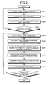
- FIG. 2 is a flow chart of the image processing of the first embodiment
- FIG. 3 is an explanatory view of a pixel gradient
- FIG. 4 is an explanatory view of a relation between a gradient vector and the direction of an edge
- FIGS. 5A and 5B are explanatory views of a histogram of oriented gradients
- FIG. 6 is an explanatory view of an anisotropic Gaussian function
- FIG. 7 is an explanatory view of a principal component analysis
- FIG. 8 is a block diagram of an image processing apparatus according to a second embodiment
- FIG. 9 is a flow chart of the image processing of the second embodiment.
- FIG. 10 is a flow chart of a process of calculating the magnitude and direction of a pixel gradient of the second embodiment.
- an image processing apparatus has a gradient calculator 101 , a histogram calculator 102 , a search unit 103 , a storing unit 104 and a filter processing unit 105 .
- the gradient calculator 101 calculates the direction and the magnitude of a gradient for each pixel of an input image using neighboring pixel values.
- the histogram calculator 102 calculates a Histogram of Oriented Gradients (HOG), which contains a plurality of sampled directions, using the directions and the magnitudes of gradients calculated for pixels in a region including a pixel being processed of the input image.
- HOG Histogram of Oriented Gradients
- a plurality of smoothing filters and Histograms of Oriented Gradients are stored in association with each other.
- a template table 1041 of Histogram of Oriented Gradients stores the plurality of Histograms of Oriented Gradients.
- a filter factor table 1042 stores filter factors in association with the Histogram of Oriented Gradients.
- the stored Histogram of Oriented Gradients are referred to as “templates of Histogram of Oriented Gradients” since they are representative histograms corresponding to the filter factors.
- the templates of Histogram of Oriented Gradients are produced in advance by learning using a sample image, or the like. The method of learning is to be described later.
- the search unit 103 searches the templates of Histogram of Oriented Gradients stored in the storing unit 104 for a Histogram of Oriented Gradients that has a minimum error with respect to the Histogram of Oriented Gradients calculated for the pixel being processed.
- the filter processing unit 105 obtains a corrected pixel value of the pixel being processed using the weighted sum of pixel values of the region including the pixel being processed. Weighting factors of the smoothing filter, which is stored in the storing unit 104 in association with the Histogram of Oriented Gradients having the minimum error, are used.
- the gradient calculator 101 selects a pixel to be processed from an input image (step S 201 ).
- (i, j) T represents a pixel position
- I i,j represents a pixel value that a pixel positioned at (i, j) T has.
- T indicates transposition of a vector or a matrix.
- the gradient calculator 101 calculates a gradient of each pixel of an input image using a difference value between a pixel value of a pixel being processed and pixel values of pixels positioned in the neighborhood (step S 202 ).
- an x-direction pixel gradient ⁇ x and a y-direction pixel gradient ⁇ y at a position (i, j) T can be defined as the following set of expressions (1).
- the pixel being processed, for which a gradient is to be calculated is a pixel positioned at (i, j) T .
- the positions of two pixels adjacent to the pixel at (i, j) T in directions of forward differences of the x direction and the y direction are (i+l, j) T and (i, j+1) T .
- the gradient vector v i,j at the position (i, j) T can be defined as the following expression (2).
- v i,j ( ⁇ x i,j , ⁇ y i,j ) T (2)
- a forward difference has been described as a method of calculating a pixel gradient
- a backward difference or a central difference may be alternatively used.
- a general gradient operator, such as Sobel, may also be used.
- the gradient calculator 101 calculates a rotation angle ⁇ , which represents the direction of an edge, and a magnitude d (step S 203 ).
- the direction ⁇ obtained by rotating the direction of the gradient vector v i,j by 90 degrees and the magnitude d are calculated using a set of expressions (3).
- the gradient calculator 101 holds the calculated direction and magnitude of each pixel's edge.
- the relationship between an edge, the gradient vector v i,j , and the rotation angle ⁇ is illustrated in FIG. 4 .
- FIG. 4 an example is illustrated in which a step edge lies along a boundary between a region with rightward ascending diagonals and a white region in an image.
- an “edge” is a linear region in which pixel values in the image sharply change.
- the gradient vector v i,j described above represents the direction normal to the boundary line that forms the edge.
- the rotation angle ⁇ that represents the direction of the edge is defined as illustrated in the drawing.
- the angle that the tangential direction of the edge forms with the x-axis is the rotation angle ⁇ .
- step S 204 it is determined whether the directions and the magnitudes of the gradients have been calculated for all pixels in the input image. If the result is “NO”, then the process returns to step S 201 and selects the next pixel to be processed. If the result is “YES”, then the process proceeds to step S 205 , and a pixel to be processed is selected (step S 205 ).
- the histogram calculator 102 calculates the Histogram of Oriented Gradients from pixels including the pixel being processed (step S 206 ).
- the Histogram of Oriented Gradients that has intensities for respective directions is produced from the directions and magnitudes of the pixel gradient vectors.
- bins of the histogram that are obtained by dividing 360 degrees by K are prepared, and the magnitudes d of the pixel gradient vectors calculated in step S 203 for pixels in the neighborhood of the pixel being processed are added into each bin. Initially, the direction of the edge is quantized into K levels.
- ⁇ i , j round ⁇ ⁇ ( ⁇ i , j 2 ⁇ ⁇ / K ) ( 4 )
- round ( ) is a function for rounding off
- 2 ⁇ /K is a quantizing step
- ⁇ is the quantized direction of the gradient vector.
- a Histogram of Oriented Gradients h[ ] is initialized at 0 as follows.
- the Histogram of Oriented Gradients can be calculated as follows.
- ⁇ r ⁇ n ⁇ r h[ ⁇ i+m,j+n ] h[ ⁇ i+m,j+n ]+d i+m,j+n (5)
- the produced Histogram of Oriented Gradients is held by the histogram calculator 102 .
- FIG. 5A schematically illustrates an example of a Histogram of Oriented Gradients with the direction quantized in eight directions.
- the result of adding magnitudes of pixel gradients calculated for pixels in a region including the pixel being processed for each direction is represented as the magnitude of an arrow.
- FIG. 5 B illustrates an example of a Histogram of Oriented Gradients produced for the pixel being processed illustrated in FIG. 5A .
- the horizontal axis indicates the number of each bin.
- the degree indicates the added magnitudes of the histogram.
- the search unit 103 determines a matching error between each of templates of Histogram of Oriented Gradients held in the template table 1041 of Histogram of Oriented Gradients of the storing unit 104 and the Histogram of Oriented Gradients calculated in step S 206 (step S 207 ), and searches for a template of Histogram of Oriented Gradients with which the matching error is minimum (step S 208 ). That is, matching evaluation values are calculated between the Histogram of Oriented Gradients of the pixel being processed and templates of Histogram of Oriented Gradients in the template table of Histogram of Oriented Gradients 1041 .
- a template of Histogram of Oriented Gradients whose evaluation value is the smallest in the calculated evaluation values is selected.
- a matching evaluation value E represents an error between the histograms. The smaller the evaluation value representing an error is, the higher similarity is indicated.
- the Histogram of Oriented Gradients of the pixel being processed calculated in step S 206 is expressed as h i,j .
- a qth template in templates of Histogram of Oriented Gradients is expressed as t q .
- the evaluation function using absolute difference values can be defined as in expression (6).
- sum of squared differences may be used.
- a template tq providing the minimum value is the template of Histogram of Oriented Gradients that is closest to the Histogram of Oriented Gradients h i,j as a result of template matching.
- the function arg min f(x) means x that provides the minimum value of f(x).
- the filter processing unit 105 acquires a filter factor stored in association with min q, which is determined in step S 208 , in the storing unit 104 (step S 209 ).
- the filter processing unit 105 determines a corrected pixel value of the pixel being processed by a convolution operation of neighboring pixel values (step S 210 ). Assuming that the filter factor acquired in step S 209 is w, the convolution can be defined as in expression (9). The left side of expression (9) is a corrected pixel value of the pixel being processed.
- I ⁇ i , j ⁇ - r ⁇ m ⁇ r , - r ⁇ n ⁇ r ⁇ w ⁇ ( m , n ) ⁇ I i + m , j + n ( 9 )
- step S 211 it is determined whether corrected pixel values have been calculated for all pixels of the input image. If the result is “NO”, then the process returns to step S 205 , and the next pixel is selected as the pixel to be processed. If the result is “YES”, then the correction process of pixel values is finished.
- filter factors may be stored in the filter factor table 1042 as long as it is suitable for a region of an image corresponding to a Histogram of Oriented Gradients stored in association with the filter factor. It is preferable that filter factors of a smoothing filter decrease as a distance from the pixel being processed increases. Filter factors, of which decreasing rate is high in a direction along which the gradient of the associated Histogram of Oriented Gradients is large and is low in a direction along which the gradient of the Histogram of Oriented Gradients is small, are preferable An example using an anisotropic Gaussian function as a weight is described.
- FIG. 6 illustrates an anisotropic Gaussian function.
- the anisotropic Gaussian function is a Gaussian function, in which standard deviations of two axes are different, allowing a pattern rotating about the x-axis.
- the filter factor using the anisotropic Gaussian function is such that the weight increases to approach to 1 as the position is closer to the center while the weight approaches to 0 as the position is more apart from the center, and is defined as follows.
- the square area of (2r+1, 2r+1) centered about the pixel being processed is set as a target range for filtering, and the foregoing weight is to be calculated for a point in the range of r ⁇ m ⁇ r, . . . , r ⁇ n ⁇ r.
- the symbol ⁇ represents an angle from the x-axis
- ⁇ + and X ⁇ are the reciprocals of dispersions of two axes of the anisotropic Gaussian function, respectively.
- Filter factors are retained in the filter factor table 1042 of the storing unit 104 .
- one pattern is formed using three parameters ( ⁇ , ⁇ + , ⁇ ⁇ ). Accordingly, the parameters are each quantized, and a finite number of filter factors are retained in the table. For example, 16 patterns are conceivable as follows.
- a method of producing a template of Histogram of Oriented Gradients for example, by learning from a sample image is described in detail.
- a method as follows can be used.
- a parameter set of an object, for which a template of Histogram of Oriented Gradients is to be produced is ( ⁇ , ⁇ + , ⁇ ⁇ ) 1
- a region corresponding to the object parameter set ( ⁇ , ⁇ + , ⁇ ⁇ ) 1 is extracted from the sample image, and the average of Histograms of Oriented Gradients in the extracted region is used as a template of Histogram of Oriented Gradients.
- principal component analysis of pixel gradients can be used.
- the direction of the main gradient vector in a region centered about the pixel being processed (referred to as a “kernel”, and, in general, a square centered about the pixel being processed is often used) can be determined by principal components of an x-direction gradient and a y-direction gradient in the kernel.
- FIG. 7 An example of the principal component analysis result is illustrated in FIG. 7 .
- the primary component axis of the distribution can be determined.
- the principal component analysis for determining v of a gradient vector corresponds to determining the primary component axis of the distribution illustrated in FIG. 7 .
- a matrix in which gradients in the kernel are arranged is defined as follows. Note that i expressed in bold represents a vector.
- the principal component axis means an axis around which the distribution of data points z is maximized. Therefore, the principal component analysis can be defined as a distribution maximizing problem as follows.
- the main edge direction and magnitude representing the local structure of the image is the above solution of the eigenvalue-eigenvector problem.
- the eigenvalue and the rotation angle ⁇ between the x-axis of the edge direction can be calculated as follows.
- an optimized filter factor is obtained by matching between Histograms of Oriented Gradients. This enables smoothing to be adaptively performed even for various edge shapes to enable prevention of degradation in image quality due to excessive smoothing.
- a second embodiment differs from the first embodiment particularly in that an image that is decoded after being coded by a coding method as exemplified in JPEG (joint photographic experts group) and MPEG (moving picture coding experts group) 1 and 2 is assumed as an input image.
- the image is basically DCT (discrete cosine transformation) coded on a block-to-block basis.
- decoding is performed on the block-to-block basis to obtain the image. Because decoding is performed discretely on the block-to-block basis, a false edge called blocking artifacts might be generated at the block boundary upon decoding. This is sensed as degradation in image quality.
- the second embodiment relates to a method of obtaining a good image with less blocking artifacts by estimating a block boundary and performing a process in accordance with the estimated result.
- An image processing apparatus differs from the first embodiment in including an estimating unit 806 as illustrated in FIG. 8 and in a method of calculating the magnitude and direction of a pixel gradient by a gradient calculator 801 .
- the estimating unit 806 estimates a boundary of a block (hereinafter referred to as a “block boundary”), which functions as a conversion unit upon coding an input image, in a frame. Any method can be used as a method of estimating the block boundary. For example, when a block size as coding information is input together with an input image, the block boundary may be estimated from the block size. If coding information of an input image is not obtained but additional information is obtained, the block boundary is estimated using the additional information.
- the additional information used for estimating the block boundary may be format information, MIME (multipurpose Internet mail extensions) information, which is character strings for specifying the format of data, or the like of a file.
- coding can be estimated to be performed in a size of 8 ⁇ 8 (pixels) in the case where the kind of a file of an input image is JPEG, in a size of 8 ⁇ 8 in the case of MPEG, and in a size of 4 ⁇ 4 in the case of H.264.
- a conversion process of coding is performed in a given block size that is often used, such as 8 ⁇ 8, and that the boundary between blocks having the given size is the block boundary.
- the gradient calculator 801 calculates a pixel gradient of each pixel as in the first embodiment. In its latter stage, when the direction and magnitude of an edge is calculated, a process based on information on a block boundary estimated by the estimating unit 806 is performed. The details thereof are to be described later.
- the estimating unit 806 estimates a block boundary of an input image (step S 901 ).
- the estimating unit 806 transmits information on the estimated block boundary to the gradient calculator 801 .
- steps S 201 and S 202 the same processes as those in the first embodiment are performed.
- the gradient calculator 801 calculates the magnitude and direction of a pixel gradient based on the information on the block boundary estimated in step S 901 (step S 902 ).
- the estimating unit 806 estimates a boundary formed by dividing a frame in a block size of 8 ⁇ 8 as the block boundary. Block boundaries are assumed to be present at positions of 8 ⁇ 8 intervals from the top-left corner of the image. A pixel gradient at the block boundary is unreliable because blocking artifacts may be generated. Therefore, the pixel gradient obtained for the block boundary is controlled by multiplying it by a certain scale so as to reduce the influence of the pixel gradient.
- a mod b is an operator for calculating a remainder when a is divided by b. If the result is “YES” in step S 9021 , the process proceeds to step S 9022 . If “NO” in step S 9021 , the process proceeds to step S 9023 .
- a value ⁇ x′ i,j calculated in step S 202 is rewritten to a value ⁇ x′ i,j obtained by multiplying the value ⁇ x′ i,j by ⁇ (step S 9022 ).
- ⁇ x′ i,j ⁇ x i,j (17) where ⁇ is a constant in the range 0 ⁇ 1.
- step S 203 the magnitude d and the direction ⁇ of a pixel gradient are calculated using the held values ⁇ x′ i,j and ⁇ y′ i,j (if the values are rewritten in steps S 9022 and 9024 , the rewritten values are used)(step S 9025 ).
- a process that multiplies a pixel gradient by a coefficient ⁇ is performed for a pixel gradient striding across a block boundary. This enables a Histogram of Oriented Gradients with less influence of a pixel gradient striding a block boundary to be produced in a process of producing a Histogram of Oriented Gradients (step S 205 ), which is to be performed later.
- smoothing in accordance with the shape of an edge can be performed in an adaptive manner based on a Histogram of Oriented Gradients in which an influence of a false edge caused by a pixel gradient striding a block boundary is excluded as much as possible.
- the image processing apparatuses of the foregoing embodiments can be implemented, for example, using general purpose computers as their basic hardware.
- Programs to be executed are made in modules including the functions described above.
- the programs, in a file in an installable format or an executable format may be provided in such a way that they are recorded on a recording medium readable by a computer, such as a CD-ROM, a CD-R or a DVD. They may also be provided in such a way that they are incorporated in advance in a ROM or the like.
Landscapes
- Engineering & Computer Science (AREA)
- Theoretical Computer Science (AREA)
- Physics & Mathematics (AREA)
- General Physics & Mathematics (AREA)
- Multimedia (AREA)
- Computer Vision & Pattern Recognition (AREA)
- Signal Processing (AREA)
- Computing Systems (AREA)
- Artificial Intelligence (AREA)
- Databases & Information Systems (AREA)
- Evolutionary Computation (AREA)
- General Health & Medical Sciences (AREA)
- Medical Informatics (AREA)
- Software Systems (AREA)
- Health & Medical Sciences (AREA)
- Image Processing (AREA)
- Studio Circuits (AREA)
- Picture Signal Circuits (AREA)
Abstract
Description
∂x i,j =I i+1,j −I i,j
∂y i,j =I i,j+1 −I i,j (1)
v i,j=(∂x i,j ,∂y i,j)T (2)
where round ( ) is a function for rounding off, 2π/K is a quantizing step, and φ is the quantized direction of the gradient vector. A Histogram of Oriented Gradients h[ ] is initialized at 0 as follows.
h[k]=0,(k=0, . . . ,K−1)
where [k] means a bin of a histogram. Assuming that a Histogram of Oriented Gradients is produced in a square area of (2r+1, 2r+1) centered about the pixel being processed, the Histogram of Oriented Gradients can be calculated as follows.
h[φ i+m,j+n ]=h[φ i+m,j+n ]+d i+m,j+n (5)
q=0,1, . . . ,Q−1
where Q is a normalization constant for causing the total sum of weights to be 1. The square area of (2r+1, 2r+1) centered about the pixel being processed is set as a target range for filtering, and the foregoing weight is to be calculated for a point in the range of r≦m≦r, . . . , r≦n≦r. The symbol θ represents an angle from the x-axis, and λ+ and X− are the reciprocals of dispersions of two axes of the anisotropic Gaussian function, respectively. Filter factors are retained in the filter factor table 1042 of the
Patterns are not limited to these patterns. As many patterns as the table size can accept may be used.
where s represents a relative pixel position in the kernel. When G is projected on the axis of the gradient vector, the result is as follows.
z=Gv (11)
where λ>0 is Lagrange's undetermined multiplier, or a parameter of a constraint for preventing a gradient vector from infinitely increasing (a constraint under which the magnitude of the gradient vector is normalized to 1). Expanding the dispersion expression can give the expression summarized as follows.
Hv−λv=0 first expression
1−v T v=0 second expression
Hv=λv (15)
From the calculations mentioned above, a parameter set (θ, λ+, λ−) for each pixel can be calculated in advance.
∂x′ i,j =α∂x i,j (17)
where α is a constant in the
∂y′ i,j =α∂y i,j (18)
Claims (9)
Applications Claiming Priority (2)
| Application Number | Priority Date | Filing Date | Title |
|---|---|---|---|
| JP2009-063087 | 2009-03-16 | ||
| JP2009063087A JP5075861B2 (en) | 2009-03-16 | 2009-03-16 | Image processing apparatus and image processing method |
Publications (2)
| Publication Number | Publication Date |
|---|---|
| US20100232697A1 US20100232697A1 (en) | 2010-09-16 |
| US8224110B2 true US8224110B2 (en) | 2012-07-17 |
Family
ID=42730751
Family Applications (1)
| Application Number | Title | Priority Date | Filing Date |
|---|---|---|---|
| US12/560,838 Active 2031-01-25 US8224110B2 (en) | 2009-03-16 | 2009-09-16 | Image processing apparatus and image processing method |
Country Status (2)
| Country | Link |
|---|---|
| US (1) | US8224110B2 (en) |
| JP (1) | JP5075861B2 (en) |
Cited By (7)
| Publication number | Priority date | Publication date | Assignee | Title |
|---|---|---|---|---|
| US20120114171A1 (en) * | 2010-11-10 | 2012-05-10 | Raytheon Company | Edge diversity object detection |
| US20130170700A1 (en) * | 2011-12-30 | 2013-07-04 | Altek Corporation | Image Capturing Device Capable of Simplifying Characteristic Value Sets of Captured Images and Control Method Thereof |
| US9239943B2 (en) | 2014-05-29 | 2016-01-19 | Datalogic ADC, Inc. | Object recognition for exception handling in automatic machine-readable symbol reader systems |
| US9396404B2 (en) * | 2014-08-04 | 2016-07-19 | Datalogic ADC, Inc. | Robust industrial optical character recognition |
| US9721203B1 (en) | 2016-11-10 | 2017-08-01 | Google Inc. | Performing kernel striding in hardware |
| US9798948B2 (en) | 2015-07-31 | 2017-10-24 | Datalogic IP Tech, S.r.l. | Optical character recognition localization tool |
| US11386636B2 (en) | 2019-04-04 | 2022-07-12 | Datalogic Usa, Inc. | Image preprocessing for optical character recognition |
Families Citing this family (17)
| Publication number | Priority date | Publication date | Assignee | Title |
|---|---|---|---|---|
| US7894668B1 (en) * | 2006-09-28 | 2011-02-22 | Fonar Corporation | System and method for digital image intensity correction |
| US20100054606A1 (en) * | 2008-08-29 | 2010-03-04 | Kabushiki Kaisha Toshiba | Image processing apparatus, image processing method, and computer program product |
| JP4585603B1 (en) * | 2009-09-18 | 2010-11-24 | 株式会社東芝 | Image processing apparatus, display apparatus, and image processing method |
| WO2012098854A1 (en) * | 2011-01-20 | 2012-07-26 | 日本電気株式会社 | Image processing system, image processing method, and image processing program |
| US8831381B2 (en) | 2012-01-26 | 2014-09-09 | Qualcomm Incorporated | Detecting and correcting skew in regions of text in natural images |
| US9064191B2 (en) | 2012-01-26 | 2015-06-23 | Qualcomm Incorporated | Lower modifier detection and extraction from devanagari text images to improve OCR performance |
| US9367737B2 (en) * | 2012-03-19 | 2016-06-14 | Honeywell International Inc. | Floor plan space detection |
| US9262699B2 (en) | 2012-07-19 | 2016-02-16 | Qualcomm Incorporated | Method of handling complex variants of words through prefix-tree based decoding for Devanagiri OCR |
| US9076242B2 (en) | 2012-07-19 | 2015-07-07 | Qualcomm Incorporated | Automatic correction of skew in natural images and video |
| US9047540B2 (en) | 2012-07-19 | 2015-06-02 | Qualcomm Incorporated | Trellis based word decoder with reverse pass |
| US9183458B2 (en) | 2012-07-19 | 2015-11-10 | Qualcomm Incorporated | Parameter selection and coarse localization of interest regions for MSER processing |
| US9141874B2 (en) * | 2012-07-19 | 2015-09-22 | Qualcomm Incorporated | Feature extraction and use with a probability density function (PDF) divergence metric |
| US8942420B2 (en) * | 2012-10-18 | 2015-01-27 | Qualcomm Incorporated | Detecting embossed characters on form factor |
| US8995749B2 (en) * | 2013-03-28 | 2015-03-31 | Mitutoyo Corporation | Enhanced edge detection tool for edges of irregular surfaces |
| US10074167B2 (en) * | 2015-12-06 | 2018-09-11 | Kla-Tencor Corporation | Reducing registration and design vicinity induced noise for intra-die inspection |
| US10782431B2 (en) * | 2016-02-09 | 2020-09-22 | Saudi Arabian Oil Company | Smoothing seismic data |
| US9977994B2 (en) * | 2016-06-30 | 2018-05-22 | Apple Inc. | Configurable histogram-of-oriented gradients (HOG) processor |
Citations (12)
| Publication number | Priority date | Publication date | Assignee | Title |
|---|---|---|---|---|
| US5512956A (en) * | 1994-02-04 | 1996-04-30 | At&T Corp. | Adaptive spatial-temporal postprocessing for low bit-rate coded image sequences |
| JPH11191861A (en) | 1997-12-25 | 1999-07-13 | Canon Inc | Image processing unit and image processing system |
| US20020159650A1 (en) * | 2000-07-06 | 2002-10-31 | Seiko Epson Corporation | Image processing apparatus and recording medium, and image processing apparatus |
| US20020172431A1 (en) * | 2001-03-07 | 2002-11-21 | Atkins C. Brian | Digital image appearance enhancement and compressibility improvement method and system |
| US20040190787A1 (en) * | 2002-12-27 | 2004-09-30 | Yoshihiro Nakami | Image noise reduction |
| US20050213818A1 (en) * | 2003-04-28 | 2005-09-29 | Sony Corporation | Image recognition device and method, and robot device |
| US20060061673A1 (en) * | 2001-06-07 | 2006-03-23 | Seiko Epson Corporation | Image processing method, image processing program, image processing apparatus, and digital still camera using the image processing apparatus |
| US7110612B1 (en) * | 2001-10-11 | 2006-09-19 | Pixelworks, Inc. | Weighted absolute difference based noise reduction method and apparatus |
| US20080013836A1 (en) * | 2006-06-19 | 2008-01-17 | Akira Nakamura | Information Processing Device, Information Processing Method, and Program |
| US20100054606A1 (en) | 2008-08-29 | 2010-03-04 | Kabushiki Kaisha Toshiba | Image processing apparatus, image processing method, and computer program product |
| US20100061651A1 (en) | 2008-09-05 | 2010-03-11 | Kabushiki Kaisha Toshiba | Method of restoring degraded image, apparatus for restoring degraded image, and computer program product |
| US20100079630A1 (en) | 2008-09-29 | 2010-04-01 | Kabushiki Kaisha Toshiba | Image processing apparatus, imaging device, image processing method, and computer program product |
Family Cites Families (12)
| Publication number | Priority date | Publication date | Assignee | Title |
|---|---|---|---|---|
| JPH02113668A (en) * | 1988-10-21 | 1990-04-25 | Mitsubishi Electric Corp | Half tone correcting method |
| JP2679769B2 (en) * | 1992-11-16 | 1997-11-19 | 富士ゼロックス株式会社 | Image signal encoding device |
| JPH1196372A (en) * | 1997-09-16 | 1999-04-09 | Omron Corp | Method and device for processing image and recording medium of control program for image processing |
| WO2005004489A1 (en) * | 2003-07-02 | 2005-01-13 | Sony Corporation | Block distortion detection device, block distortion detection method, and video signal processing device |
| JP4613558B2 (en) * | 2003-09-16 | 2011-01-19 | パナソニック電工株式会社 | Human body detection device using images |
| JP2006087030A (en) * | 2004-09-17 | 2006-03-30 | Olympus Corp | Noise reducer |
| JP2007116580A (en) * | 2005-10-24 | 2007-05-10 | Matsushita Electric Ind Co Ltd | Image processing method and image processing device |
| JP2007312304A (en) * | 2006-05-22 | 2007-11-29 | Fujitsu Ltd | Image processing apparatus and image processing method |
| JP4981433B2 (en) * | 2006-12-18 | 2012-07-18 | 三菱重工業株式会社 | Inspection device, inspection method, inspection program, and inspection system |
| JP4988408B2 (en) * | 2007-04-09 | 2012-08-01 | 株式会社デンソー | Image recognition device |
| JP4941135B2 (en) * | 2007-07-05 | 2012-05-30 | トヨタ自動車株式会社 | Image processing device |
| US7835586B2 (en) * | 2007-08-01 | 2010-11-16 | Mitsubishi Electric Research Laboratories, Inc. | Method for filtering images with bilateral filters |
-
2009
- 2009-03-16 JP JP2009063087A patent/JP5075861B2/en not_active Expired - Fee Related
- 2009-09-16 US US12/560,838 patent/US8224110B2/en active Active
Patent Citations (12)
| Publication number | Priority date | Publication date | Assignee | Title |
|---|---|---|---|---|
| US5512956A (en) * | 1994-02-04 | 1996-04-30 | At&T Corp. | Adaptive spatial-temporal postprocessing for low bit-rate coded image sequences |
| JPH11191861A (en) | 1997-12-25 | 1999-07-13 | Canon Inc | Image processing unit and image processing system |
| US20020159650A1 (en) * | 2000-07-06 | 2002-10-31 | Seiko Epson Corporation | Image processing apparatus and recording medium, and image processing apparatus |
| US20020172431A1 (en) * | 2001-03-07 | 2002-11-21 | Atkins C. Brian | Digital image appearance enhancement and compressibility improvement method and system |
| US20060061673A1 (en) * | 2001-06-07 | 2006-03-23 | Seiko Epson Corporation | Image processing method, image processing program, image processing apparatus, and digital still camera using the image processing apparatus |
| US7110612B1 (en) * | 2001-10-11 | 2006-09-19 | Pixelworks, Inc. | Weighted absolute difference based noise reduction method and apparatus |
| US20040190787A1 (en) * | 2002-12-27 | 2004-09-30 | Yoshihiro Nakami | Image noise reduction |
| US20050213818A1 (en) * | 2003-04-28 | 2005-09-29 | Sony Corporation | Image recognition device and method, and robot device |
| US20080013836A1 (en) * | 2006-06-19 | 2008-01-17 | Akira Nakamura | Information Processing Device, Information Processing Method, and Program |
| US20100054606A1 (en) | 2008-08-29 | 2010-03-04 | Kabushiki Kaisha Toshiba | Image processing apparatus, image processing method, and computer program product |
| US20100061651A1 (en) | 2008-09-05 | 2010-03-11 | Kabushiki Kaisha Toshiba | Method of restoring degraded image, apparatus for restoring degraded image, and computer program product |
| US20100079630A1 (en) | 2008-09-29 | 2010-04-01 | Kabushiki Kaisha Toshiba | Image processing apparatus, imaging device, image processing method, and computer program product |
Cited By (11)
| Publication number | Priority date | Publication date | Assignee | Title |
|---|---|---|---|---|
| US20120114171A1 (en) * | 2010-11-10 | 2012-05-10 | Raytheon Company | Edge diversity object detection |
| US8553933B2 (en) * | 2010-11-10 | 2013-10-08 | Raytheon Company | Edge diversity object detection |
| US20130170700A1 (en) * | 2011-12-30 | 2013-07-04 | Altek Corporation | Image Capturing Device Capable of Simplifying Characteristic Value Sets of Captured Images and Control Method Thereof |
| US8908974B2 (en) * | 2011-12-30 | 2014-12-09 | Altek Corporation | Image capturing device capable of simplifying characteristic value sets of captured images and control method thereof |
| US9239943B2 (en) | 2014-05-29 | 2016-01-19 | Datalogic ADC, Inc. | Object recognition for exception handling in automatic machine-readable symbol reader systems |
| US9396404B2 (en) * | 2014-08-04 | 2016-07-19 | Datalogic ADC, Inc. | Robust industrial optical character recognition |
| US9798948B2 (en) | 2015-07-31 | 2017-10-24 | Datalogic IP Tech, S.r.l. | Optical character recognition localization tool |
| US9721203B1 (en) | 2016-11-10 | 2017-08-01 | Google Inc. | Performing kernel striding in hardware |
| US10733505B2 (en) | 2016-11-10 | 2020-08-04 | Google Llc | Performing kernel striding in hardware |
| US11816532B2 (en) | 2016-11-10 | 2023-11-14 | Google Llc | Performing kernel striding in hardware |
| US11386636B2 (en) | 2019-04-04 | 2022-07-12 | Datalogic Usa, Inc. | Image preprocessing for optical character recognition |
Also Published As
| Publication number | Publication date |
|---|---|
| JP2010219768A (en) | 2010-09-30 |
| US20100232697A1 (en) | 2010-09-16 |
| JP5075861B2 (en) | 2012-11-21 |
Similar Documents
| Publication | Publication Date | Title |
|---|---|---|
| US8224110B2 (en) | Image processing apparatus and image processing method | |
| US6990233B2 (en) | Apparatus and method for extracting object based on feature matching between segmented regions in images | |
| US8718321B2 (en) | Method of image processing | |
| KR101117837B1 (en) | Multi-image feature matching using multi-scale oriented patches | |
| US9679370B2 (en) | Image processing device and image processing method | |
| US9042656B2 (en) | Image signature extraction device | |
| US8150181B2 (en) | Method of filtering a video sequence image from spurious motion effects | |
| US8515177B2 (en) | Image processing apparatus, image processing method, and program | |
| US20150279021A1 (en) | Video object tracking in traffic monitoring | |
| US20070173744A1 (en) | System and method for detecting intervertebral disc alignment using vertebrae segmentation | |
| JP4588575B2 (en) | Method, apparatus and program for detecting multiple objects in digital image | |
| US20140125666A1 (en) | Apparatus and method for generating depth map of stereoscopic image | |
| US20130308853A1 (en) | System and method for synthesizing portrait sketch from a photo | |
| US10762389B2 (en) | Methods and systems of segmentation of a document | |
| US20140050411A1 (en) | Apparatus and method for generating image feature data | |
| US9077926B2 (en) | Image processing method and image processing apparatus | |
| JP2009064434A (en) | Determination method, determination system and computer readable medium | |
| US7388988B2 (en) | Systems and methods for processing boundary information of a graphical object | |
| US20110255792A1 (en) | Information processing apparatus, control method for the same, and computer-readable storage medium | |
| CN105263026B (en) | Global vector acquisition methods based on probability statistics and image gradient information | |
| EP2966613A1 (en) | Method and apparatus for generating a super-resolved image from an input image | |
| JP4477439B2 (en) | Image segmentation system | |
| CN109063537B (en) | Hyperspectral image preprocessing method for unmixing of abnormal small target | |
| US20110135181A1 (en) | polynomial fitting based segmentation algorithm for pulmonary nodule in chest radiograph | |
| WO2014178241A1 (en) | Image processing device, image processing method, and image processing program |
Legal Events
| Date | Code | Title | Description |
|---|---|---|---|
| AS | Assignment |
Owner name: KABUSHIKI KAISHA TOSHIBA, JAPAN Free format text: ASSIGNMENT OF ASSIGNORS INTEREST;ASSIGNORS:MISHIMA, NAO;ITOH, GOH;REEL/FRAME:023569/0020 Effective date: 20091001 |
|
| STCF | Information on status: patent grant |
Free format text: PATENTED CASE |
|
| FPAY | Fee payment |
Year of fee payment: 4 |
|
| AS | Assignment |
Owner name: TOSHIBA VISUAL SOLUTIONS CORPORATION, JAPAN Free format text: ASSIGNMENT OF ASSIGNORS INTEREST;ASSIGNOR:KABUSHIKI KAISHA TOSHIBA;REEL/FRAME:046640/0626 Effective date: 20180720 |
|
| AS | Assignment |
Owner name: HISENSE VISUAL TECHNOLOGY CO., LTD., CHINA Free format text: ASSIGNMENT OF ASSIGNORS INTEREST;ASSIGNOR:TOSHIBA VISUAL SOLUTIONS CORPORATION;REEL/FRAME:051493/0333 Effective date: 20191225 |
|
| MAFP | Maintenance fee payment |
Free format text: PAYMENT OF MAINTENANCE FEE, 8TH YEAR, LARGE ENTITY (ORIGINAL EVENT CODE: M1552); ENTITY STATUS OF PATENT OWNER: LARGE ENTITY Year of fee payment: 8 |
|
| AS | Assignment |
Owner name: MAXELL, LTD., JAPAN Free format text: ASSIGNMENT OF ASSIGNORS INTEREST;ASSIGNOR:HISENSE VISUAL TECHNOLOGY CO., LTD.;REEL/FRAME:056681/0441 Effective date: 20210531 |
|
| AS | Assignment |
Owner name: MAXELL HOLDINGS, LTD., JAPAN Free format text: MERGER;ASSIGNOR:MAXELL, LTD.;REEL/FRAME:058255/0579 Effective date: 20211001 |
|
| AS | Assignment |
Owner name: MAXELL, LTD., JAPAN Free format text: CHANGE OF NAME;ASSIGNOR:MAXELL HOLDINGS, LTD.;REEL/FRAME:058666/0407 Effective date: 20211001 |
|
| MAFP | Maintenance fee payment |
Free format text: PAYMENT OF MAINTENANCE FEE, 12TH YEAR, LARGE ENTITY (ORIGINAL EVENT CODE: M1553); ENTITY STATUS OF PATENT OWNER: LARGE ENTITY Year of fee payment: 12 |