US8209799B2 - Gap protection device for examining table - Google Patents
Gap protection device for examining table Download PDFInfo
- Publication number
- US8209799B2 US8209799B2 US12/953,156 US95315610A US8209799B2 US 8209799 B2 US8209799 B2 US 8209799B2 US 95315610 A US95315610 A US 95315610A US 8209799 B2 US8209799 B2 US 8209799B2
- Authority
- US
- United States
- Prior art keywords
- examining table
- protection device
- gap
- chain
- gap protection
- Prior art date
- Legal status (The legal status is an assumption and is not a legal conclusion. Google has not performed a legal analysis and makes no representation as to the accuracy of the status listed.)
- Active
Links
- 239000004033 plastic Substances 0.000 claims description 17
- 229910000831 Steel Inorganic materials 0.000 claims description 3
- 239000010959 steel Substances 0.000 claims description 3
- 238000005096 rolling process Methods 0.000 claims description 2
- 238000010586 diagram Methods 0.000 description 4
- 238000003745 diagnosis Methods 0.000 description 3
- 239000000696 magnetic material Substances 0.000 description 2
- 239000004677 Nylon Substances 0.000 description 1
- 238000005452 bending Methods 0.000 description 1
- 230000005540 biological transmission Effects 0.000 description 1
- -1 for example Substances 0.000 description 1
- 238000004519 manufacturing process Methods 0.000 description 1
- 239000000463 material Substances 0.000 description 1
- 238000000034 method Methods 0.000 description 1
- 238000012986 modification Methods 0.000 description 1
- 230000004048 modification Effects 0.000 description 1
- 229920001778 nylon Polymers 0.000 description 1
- 238000011017 operating method Methods 0.000 description 1
- 238000004804 winding Methods 0.000 description 1
Images


Classifications
-
- A—HUMAN NECESSITIES
- A61—MEDICAL OR VETERINARY SCIENCE; HYGIENE
- A61B—DIAGNOSIS; SURGERY; IDENTIFICATION
- A61B5/00—Measuring for diagnostic purposes; Identification of persons
- A61B5/05—Detecting, measuring or recording for diagnosis by means of electric currents or magnetic fields; Measuring using microwaves or radio waves
- A61B5/055—Detecting, measuring or recording for diagnosis by means of electric currents or magnetic fields; Measuring using microwaves or radio waves involving electronic [EMR] or nuclear [NMR] magnetic resonance, e.g. magnetic resonance imaging
-
- A—HUMAN NECESSITIES
- A61—MEDICAL OR VETERINARY SCIENCE; HYGIENE
- A61B—DIAGNOSIS; SURGERY; IDENTIFICATION
- A61B6/00—Apparatus for radiation diagnosis, e.g. combined with radiation therapy equipment
- A61B6/04—Positioning of patients; Tiltable beds or the like
- A61B6/0407—Supports, e.g. tables or beds, for the body or parts of the body
-
- G—PHYSICS
- G01—MEASURING; TESTING
- G01R—MEASURING ELECTRIC VARIABLES; MEASURING MAGNETIC VARIABLES
- G01R33/00—Arrangements or instruments for measuring magnetic variables
- G01R33/20—Arrangements or instruments for measuring magnetic variables involving magnetic resonance
- G01R33/28—Details of apparatus provided for in groups G01R33/44 - G01R33/64
- G01R33/288—Provisions within MR facilities for enhancing safety during MR, e.g. reduction of the specific absorption rate [SAR], detection of ferromagnetic objects in the scanner room
Definitions
- the present embodiments relate to a gap protection device for an examining table.
- a conventional medical examining table such as an MRI examining table, has two functions: horizontal movement and vertical movement, so as to carry a patient vertically or horizontally according to the requirements for diagnosis.
- the gap between the body and the non-moving part of the examining table may not be covered with a fixed cover shell. Otherwise, the cover shell may collide with the table body when the table body is moving, which inconveniences the medical diagnosis.
- a gap 10 may be reserved between the table body and the non-moving part of the examining table.
- the finger of a patient enters the gap 10 accidentally when the examining table is moving, the finger may be hurt or even broken.
- a gap protection device for an examining table that may cover the gap between a body and a non-moving part of the examining table may be provided.
- a gap protection device for an examining table that is not affected by the magnetic field working environment of the examining table may also be provided.
- a gap protection device for an examining table includes a guide rail, a protecting chain, a rigid rope and a roller.
- the guide rail may be fixed onto the non-moving part of the examining table.
- One end of the protecting chain is connected to the body of the examining table and is slidable along the guide rail to cover the gap between the body and the non-moving part of the examining table.
- the two ends of the rigid rope are respectively connected to the two ends of the protecting chain, making the rope and the chain form a closed loop.
- the roller is fixed onto the non-moving part of the examining table, with the rigid rope being wound around the roller.
- the gap protection device includes a guide part.
- the guide part is connected to the one end of the protection chain connected to the examining table, and the rigid rope is wound around the guide part.
- the gap protection device includes a mounting plate.
- the mounting plate is fixed on the body of the examining table.
- the guide part is fixed on the mounting plate, and the rigid rope is wound around the guide part and is fixed on the mounting plate.
- the gap protection device includes a set of springs, with one end of each of the springs being connected to a rolling shaft of the roller, and the other end of each of the springs being fixed on the non-moving part of the examining table.
- the protection chain is a plastic chain
- the plastic chain is formed by a plurality of plastic chain plates that are connected in succession.
- the rigid rope is a steel wire rope.
- the gap between the table body and the non-moving part of the examining table may be effectively protected, thus ensuring safety in operation.
- the arrangement of the roller and the spring may provide a buffer to the gap protection device and make the movement of the device more stable.
- the gap protection device of the present embodiments is subject to an evenly applied force, has good durability, simple structure and low costs for manufacturing.
- the main parts of the gap protection device are made of non-magnetic materials so the main parts do not tend to have any influence on the magnetic environment.
- FIG. 1 is a schematic diagram of an examining table
- FIG. 2 is a schematic diagram of one embodiment of a gap protection device for an examining table
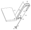
- FIG. 3 is a schematic diagram of another embodiment of the gap protection device for an examining table.
- FIG. 4 is a schematic diagram of one embodiment of the gap protection device shown in FIG. 3 in an operating state.
- a gap protection device for an examining table includes a guide rail 22 , a protecting chain 24 , a rigid rope 32 and a roller 42 .
- the guide rail 22 and the roller 42 are fixed onto a non-moving part 16 of the examining table (as shown in FIG. 4 ).
- “Non-moving part” may not refer to any singular part of the examining table, but may refer generally to the fixed parts of the examining table.
- the Examining table is for an MRI or a CT system.
- a first end 26 of the protecting chain 24 is connected to the table body 12 .
- the protecting chain 24 may slide along the guide rail 22 to cover a gap between the table body 12 and the non-moving part 16 of the examining table.
- the protecting chain 24 moves synchronously to cover the gap between the table body 12 and the non-moving part 16 of the examining table with the protecting chain 24 .
- the gap protection device of the present embodiments may include a guide part 34 .
- the guide part 34 is connected to the first end 26 of the protecting chain 24 connected to the table body 12 .
- the rigid rope 32 is wound around the guide part 34 .
- the guide part 34 may be either a rotatable guide pulley or a fixed guide structure, for example.
- the protecting chain 24 is made of a non-magnetic material such as, for example, plastic.
- the plastic chain may be formed by a plurality of plastic chain plates joined in succession and disposed on the guide rail 22 .
- the plurality of plastic chain plates may be slidable back and forth along the guide rail 22 . Free rotation between any two of the plastic chain plates on the plastic chain is prevented, so the plastic chain may bend in one direction to wind around the guide rail while not bending in the opposite direction, thus avoiding hurting the fingers of a patient.
- one end of the rigid rope 32 is fixed onto a second end 28 of the protecting chain 24 , and another end of the rigid rope 32 is fixed onto the first end 26 of the protecting chain 24 , the rigid rope 32 winding around the guide part 34 and the roller 42 , thus forming a closed loop.
- the rigid rope 32 may be any number of materials such as, for example, a steel wire rope or a nylon rope.
- the roller 42 is fixed onto the non-moving part 16 of the examining table. Therefore, the table body may move synchronously with the protecting chain 24 and the rigid rope 32 .
- the gap protection device includes a mounting plate 36 .
- the mounting plate 36 may be fixed onto the body 12 of the examining table, and the guide part 34 is fixed onto the mounting plate 36 to connect the protecting chain 24 via the mounting plate 36 .
- the rigid rope 32 is fixed onto the mounting plate 36 and winds around the guide part 34 to achieve the connection to the protecting chain 24 .
- the embodiment shown in FIG. 2 makes the connection between the protecting chain 24 , the table body 12 and the rigid rope 32 more stable, and at the same time, the wiring of the rigid rope 32 more compact and regular (e.g., to realize the design of a rigid rope circulating structure in a tight space).
- the gap protection device may include a set of springs 44 .
- One end of each spring 44 is connected to the roller 42 , and another end of each spring 44 is fixed onto the non-moving part 16 of the examining table.
- the springs 44 are for pre-tensioning and for providing a proper buffer for the gap protection device to increase stability of the gap protection device.
- the springs 44 may not extend or compress significantly along with the movement of the rigid rope 32 .
- the springs 44 are disposed at a position far away from the operating magnetic field, so the springs 44 may not be affected by the magnetic field.
- the gap protection device of the present embodiments is disposed on each of two sides of the examining table body 12 .
- the protecting chain 24 covers a gap beside a cover shell 14 for protection, thus preventing any foreign matter from entering the gap accidentally when the examining table is moving.
- the closed loop formed by the protecting chain 24 and the rigid rope 32 e.g., show in FIG. 2 or 3
- the closed loop formed by the protecting chain 24 and the rigid rope 32 circulates synchronously under the drive of the table body 12 , thus completely covering the gap beside the cover shell 14 as the protecting chain 24 slides around the guide rail 22 .
- the closed loop formed by the protecting chain 24 and the rigid rope 32 circulates synchronously in the opposite direction, thus completely covering the gap beside the cover shell 14 in the same way.
- the gap protection device may also be used in a horizontal movement structure for the examining table and may also serve to prevent foreign matter from entering the gap between the table body and the non-moving part.
- the protecting chain and the rigid rope form a closed loop in the gap protection device of the present embodiments, such a full-circulation movement makes the structure more stable and the force applied more uniform.
- the possibility that the transmission part is magnetized and thus affects the operation magnetic field may be avoided since the protecting chain is made of, for example, plastic.
- the plastic chain of the present embodiments is formed by a plurality of plastic chain plates joined in succession, which significantly reduces the flexibility and thus increases the stability and durability of the plastic chain.
Abstract
Description
Claims (7)
Applications Claiming Priority (3)
| Application Number | Priority Date | Filing Date | Title |
|---|---|---|---|
| CN2009202710796U CN201595843U (en) | 2009-11-26 | 2009-11-26 | Clearance protection device of examining table |
| CN200920271079.6 | 2009-11-26 | ||
| CN200920271079U | 2009-11-26 |
Publications (2)
| Publication Number | Publication Date |
|---|---|
| US20110119830A1 US20110119830A1 (en) | 2011-05-26 |
| US8209799B2 true US8209799B2 (en) | 2012-07-03 |
Family
ID=42806884
Family Applications (1)
| Application Number | Title | Priority Date | Filing Date |
|---|---|---|---|
| US12/953,156 Active US8209799B2 (en) | 2009-11-26 | 2010-11-23 | Gap protection device for examining table |
Country Status (3)
| Country | Link |
|---|---|
| US (1) | US8209799B2 (en) |
| CN (1) | CN201595843U (en) |
| DE (1) | DE102010062028B4 (en) |
Families Citing this family (2)
| Publication number | Priority date | Publication date | Assignee | Title |
|---|---|---|---|---|
| CN103006253B (en) * | 2012-12-21 | 2014-03-26 | 沈阳东软医疗系统有限公司 | Support equipment for scanning |
| US10694976B2 (en) * | 2017-05-04 | 2020-06-30 | Elekta Ltd. | Squeeze protection |
Citations (5)
| Publication number | Priority date | Publication date | Assignee | Title |
|---|---|---|---|---|
| US5084925A (en) | 1991-02-19 | 1992-02-04 | Product Strategies, Inc. | Hospital bed guard extender |
| US5943714A (en) * | 1998-12-16 | 1999-08-31 | Dignam; David | Suspended sleeping platform assembly |
| US5987666A (en) | 1999-03-15 | 1999-11-23 | St. Luke Foundation | Gap-filling pad disposable between a mattress and a bed rail |
| US20050125899A1 (en) * | 1998-12-11 | 2005-06-16 | Hanson Thomas W. | Hospital bed mechanisms |
| US20070226901A1 (en) * | 2006-01-30 | 2007-10-04 | Rbw Industries, Inc. | Bed Lift Mechanism For A Vehicle |
Family Cites Families (5)
| Publication number | Priority date | Publication date | Assignee | Title |
|---|---|---|---|---|
| DE1037647B (en) * | 1956-06-13 | 1958-08-28 | Mueller C H F Ag | Device for motorized movement of loads |
| DE8909245U1 (en) * | 1989-07-31 | 1989-10-19 | Siemens Ag, 1000 Berlin Und 8000 Muenchen, De | |
| US5940911A (en) * | 1997-11-10 | 1999-08-24 | Wang; Yi-Lung | Multi-functional bed structure |
| DE50014094D1 (en) * | 2000-12-15 | 2007-04-05 | Gerhart W Vilsmeier | liftbed |
| DE102009009838A1 (en) * | 2008-12-22 | 2010-06-24 | Siemens Aktiengesellschaft | Support for patient receiving table in computer tomography device, has side parts arranged at base part in longitudinal direction of side parts, where base and side parts are made of completely transparent material against X-ray radiation |
-
2009
- 2009-11-26 CN CN2009202710796U patent/CN201595843U/en not_active Expired - Lifetime
-
2010
- 2010-11-23 US US12/953,156 patent/US8209799B2/en active Active
- 2010-11-26 DE DE102010062028A patent/DE102010062028B4/en active Active
Patent Citations (5)
| Publication number | Priority date | Publication date | Assignee | Title |
|---|---|---|---|---|
| US5084925A (en) | 1991-02-19 | 1992-02-04 | Product Strategies, Inc. | Hospital bed guard extender |
| US20050125899A1 (en) * | 1998-12-11 | 2005-06-16 | Hanson Thomas W. | Hospital bed mechanisms |
| US5943714A (en) * | 1998-12-16 | 1999-08-31 | Dignam; David | Suspended sleeping platform assembly |
| US5987666A (en) | 1999-03-15 | 1999-11-23 | St. Luke Foundation | Gap-filling pad disposable between a mattress and a bed rail |
| US20070226901A1 (en) * | 2006-01-30 | 2007-10-04 | Rbw Industries, Inc. | Bed Lift Mechanism For A Vehicle |
Also Published As
| Publication number | Publication date |
|---|---|
| DE102010062028B4 (en) | 2013-03-28 |
| US20110119830A1 (en) | 2011-05-26 |
| CN201595843U (en) | 2010-10-06 |
| DE102010062028A1 (en) | 2011-06-01 |
Similar Documents
| Publication | Publication Date | Title |
|---|---|---|
| US8209799B2 (en) | Gap protection device for examining table | |
| US20130034334A1 (en) | Sliding holder having flexible cable support | |
| EP2641762A3 (en) | Sunshade apparatus | |
| US20170099070A1 (en) | Wrist phone | |
| JP2009538544A (en) | Sliding mechanism for portable devices | |
| US5474068A (en) | Magnetic resonance imaging apparatus | |
| US20200309839A1 (en) | Wire diagnosis apparatus mounted on lifting device | |
| CN105453358B (en) | The wire structures of spiral | |
| US20210370123A1 (en) | Resistance device | |
| US20100325793A1 (en) | Examination bed movement device | |
| US20110198947A1 (en) | Dust cover plate for linear motor | |
| CN203885518U (en) | Chest radiological protection device | |
| TW201352115A (en) | Routing cable mechanism and portable electronic device | |
| WO2013115059A1 (en) | Spring unit and slide mechanism | |
| CN110949279A (en) | Flat cable winding device and flat cable routing structure | |
| CN205697770U (en) | Anti-pinch device and sick bed | |
| KR101739967B1 (en) | Dual cable reel | |
| CN116149429A (en) | Electronic equipment | |
| CN109474723A (en) | The ejecting mechanism and mobile terminal of camera | |
| CN211830035U (en) | Wire arranging device | |
| CN102502342B (en) | Reciprocating wrapping machine | |
| CN209420593U (en) | A kind of novel livestock breeding fence | |
| JP2012193612A (en) | Sheet shutter | |
| CN106734044B (en) | A kind of adjustable end stop mechanism | |
| US8509423B2 (en) | Synchronous pull device for slide cover mechanism |
Legal Events
| Date | Code | Title | Description |
|---|---|---|---|
| AS | Assignment |
Owner name: SIEMENS AKTIENGESELLSCHAFT, GERMANY Free format text: ASSIGNMENT OF ASSIGNORS INTEREST;ASSIGNOR:SIEMENS SHANGHAI MEDICAL EQUIPMENT LTD.;REEL/FRAME:025847/0024 Effective date: 20110105 Owner name: SIEMENS SHANGHAI MEDICAL EQUIPMENT LTD., CHINA Free format text: ASSIGNMENT OF ASSIGNORS INTEREST;ASSIGNORS:SHANG, HONG;YANG, NING TAO;ZHANG, XIANG;AND OTHERS;REEL/FRAME:025847/0016 Effective date: 20110105 |
|
| STCF | Information on status: patent grant |
Free format text: PATENTED CASE |
|
| FPAY | Fee payment |
Year of fee payment: 4 |
|
| AS | Assignment |
Owner name: SIEMENS HEALTHCARE GMBH, GERMANY Free format text: ASSIGNMENT OF ASSIGNORS INTEREST;ASSIGNOR:SIEMENS AKTIENGESELLSCHAFT;REEL/FRAME:039271/0561 Effective date: 20160610 |
|
| MAFP | Maintenance fee payment |
Free format text: PAYMENT OF MAINTENANCE FEE, 8TH YEAR, LARGE ENTITY (ORIGINAL EVENT CODE: M1552); ENTITY STATUS OF PATENT OWNER: LARGE ENTITY Year of fee payment: 8 |
|
| MAFP | Maintenance fee payment |
Free format text: PAYMENT OF MAINTENANCE FEE, 12TH YEAR, LARGE ENTITY (ORIGINAL EVENT CODE: M1553); ENTITY STATUS OF PATENT OWNER: LARGE ENTITY Year of fee payment: 12 |
|
| AS | Assignment |
Owner name: SIEMENS HEALTHINEERS AG, GERMANY Free format text: ASSIGNMENT OF ASSIGNORS INTEREST;ASSIGNOR:SIEMENS HEALTHCARE GMBH;REEL/FRAME:066088/0256 Effective date: 20231219 |