US8152281B2 - Liquid ejecting head and liquid ejecting apparatus - Google Patents
Liquid ejecting head and liquid ejecting apparatus Download PDFInfo
- Publication number
- US8152281B2 US8152281B2 US12/635,960 US63596009A US8152281B2 US 8152281 B2 US8152281 B2 US 8152281B2 US 63596009 A US63596009 A US 63596009A US 8152281 B2 US8152281 B2 US 8152281B2
- Authority
- US
- United States
- Prior art keywords
- pressure generating
- base member
- angular portion
- adhesive agent
- reservoir
- Prior art date
- Legal status (The legal status is an assumption and is not a legal conclusion. Google has not performed a legal analysis and makes no representation as to the accuracy of the status listed.)
- Active, expires
Links
- 239000007788 liquid Substances 0.000 title claims abstract description 43
- 239000000853 adhesive Substances 0.000 claims abstract description 63
- 238000005192 partition Methods 0.000 claims abstract description 61
- 238000000638 solvent extraction Methods 0.000 claims description 8
- 230000009471 action Effects 0.000 claims description 2
- 239000000758 substrate Substances 0.000 description 82
- 239000012528 membrane Substances 0.000 description 46
- 239000000463 material Substances 0.000 description 16
- 238000005452 bending Methods 0.000 description 9
- 239000013078 crystal Substances 0.000 description 7
- 238000004519 manufacturing process Methods 0.000 description 7
- XUIMIQQOPSSXEZ-UHFFFAOYSA-N Silicon Chemical compound [Si] XUIMIQQOPSSXEZ-UHFFFAOYSA-N 0.000 description 6
- 229910052710 silicon Inorganic materials 0.000 description 6
- 239000010703 silicon Substances 0.000 description 6
- 230000006378 damage Effects 0.000 description 5
- 239000004734 Polyphenylene sulfide Substances 0.000 description 4
- 229920000069 polyphenylene sulfide Polymers 0.000 description 4
- 230000008901 benefit Effects 0.000 description 3
- 238000007599 discharging Methods 0.000 description 3
- 229910052451 lead zirconate titanate Inorganic materials 0.000 description 3
- HFGPZNIAWCZYJU-UHFFFAOYSA-N lead zirconate titanate Chemical compound [O-2].[O-2].[O-2].[O-2].[O-2].[Ti+4].[Zr+4].[Pb+2] HFGPZNIAWCZYJU-UHFFFAOYSA-N 0.000 description 3
- 238000007789 sealing Methods 0.000 description 3
- 229910001220 stainless steel Inorganic materials 0.000 description 3
- 239000010935 stainless steel Substances 0.000 description 3
- 239000010936 titanium Substances 0.000 description 3
- 229910052719 titanium Inorganic materials 0.000 description 3
- OGIDPMRJRNCKJF-UHFFFAOYSA-N titanium oxide Inorganic materials [Ti]=O OGIDPMRJRNCKJF-UHFFFAOYSA-N 0.000 description 3
- 229910052726 zirconium Inorganic materials 0.000 description 3
- GWEVSGVZZGPLCZ-UHFFFAOYSA-N Titan oxide Chemical compound O=[Ti]=O GWEVSGVZZGPLCZ-UHFFFAOYSA-N 0.000 description 2
- PQCCZSBUXOQGIU-UHFFFAOYSA-N [La].[Pb] Chemical compound [La].[Pb] PQCCZSBUXOQGIU-UHFFFAOYSA-N 0.000 description 2
- 230000000694 effects Effects 0.000 description 2
- 239000003822 epoxy resin Substances 0.000 description 2
- 238000005530 etching Methods 0.000 description 2
- 239000002241 glass-ceramic Substances 0.000 description 2
- 239000010931 gold Substances 0.000 description 2
- 238000009413 insulation Methods 0.000 description 2
- 229910052746 lanthanum Inorganic materials 0.000 description 2
- 229910052745 lead Inorganic materials 0.000 description 2
- 229910052749 magnesium Inorganic materials 0.000 description 2
- 239000011777 magnesium Substances 0.000 description 2
- CPLXHLVBOLITMK-UHFFFAOYSA-N magnesium oxide Inorganic materials [Mg]=O CPLXHLVBOLITMK-UHFFFAOYSA-N 0.000 description 2
- 239000000395 magnesium oxide Substances 0.000 description 2
- AXZKOIWUVFPNLO-UHFFFAOYSA-N magnesium;oxygen(2-) Chemical compound [O-2].[Mg+2] AXZKOIWUVFPNLO-UHFFFAOYSA-N 0.000 description 2
- 238000000034 method Methods 0.000 description 2
- 239000000203 mixture Substances 0.000 description 2
- 229910000480 nickel oxide Inorganic materials 0.000 description 2
- 229920000647 polyepoxide Polymers 0.000 description 2
- 230000008569 process Effects 0.000 description 2
- 238000000018 DNA microarray Methods 0.000 description 1
- FYYHWMGAXLPEAU-UHFFFAOYSA-N Magnesium Chemical compound [Mg] FYYHWMGAXLPEAU-UHFFFAOYSA-N 0.000 description 1
- 230000001154 acute effect Effects 0.000 description 1
- 229910010293 ceramic material Inorganic materials 0.000 description 1
- 239000002131 composite material Substances 0.000 description 1
- 239000004020 conductor Substances 0.000 description 1
- NKZSPGSOXYXWQA-UHFFFAOYSA-N dioxido(oxo)titanium;lead(2+) Chemical compound [Pb+2].[O-][Ti]([O-])=O NKZSPGSOXYXWQA-UHFFFAOYSA-N 0.000 description 1
- 230000005684 electric field Effects 0.000 description 1
- 239000007772 electrode material Substances 0.000 description 1
- 239000011521 glass Substances 0.000 description 1
- PCHJSUWPFVWCPO-UHFFFAOYSA-N gold Chemical compound [Au] PCHJSUWPFVWCPO-UHFFFAOYSA-N 0.000 description 1
- 229910052737 gold Inorganic materials 0.000 description 1
- 239000004973 liquid crystal related substance Substances 0.000 description 1
- 229910052751 metal Inorganic materials 0.000 description 1
- 239000002184 metal Substances 0.000 description 1
- 239000007769 metal material Substances 0.000 description 1
- 229910044991 metal oxide Inorganic materials 0.000 description 1
- 150000004706 metal oxides Chemical class 0.000 description 1
- 229910052758 niobium Inorganic materials 0.000 description 1
- 239000010955 niobium Substances 0.000 description 1
- URLJKFSTXLNXLG-UHFFFAOYSA-N niobium(5+);oxygen(2-) Chemical compound [O-2].[O-2].[O-2].[O-2].[O-2].[Nb+5].[Nb+5] URLJKFSTXLNXLG-UHFFFAOYSA-N 0.000 description 1
- GNRSAWUEBMWBQH-UHFFFAOYSA-N oxonickel Chemical compound [Ni]=O GNRSAWUEBMWBQH-UHFFFAOYSA-N 0.000 description 1
- 230000035515 penetration Effects 0.000 description 1
- 230000009467 reduction Effects 0.000 description 1
- 229920005989 resin Polymers 0.000 description 1
- 239000011347 resin Substances 0.000 description 1
- 239000004065 semiconductor Substances 0.000 description 1
- 229910000679 solder Inorganic materials 0.000 description 1
- 238000005476 soldering Methods 0.000 description 1
- 239000000126 substance Substances 0.000 description 1
- 230000026683 transduction Effects 0.000 description 1
- 238000010361 transduction Methods 0.000 description 1
- 230000009466 transformation Effects 0.000 description 1
Images


Classifications
-
- B—PERFORMING OPERATIONS; TRANSPORTING
- B41—PRINTING; LINING MACHINES; TYPEWRITERS; STAMPS
- B41J—TYPEWRITERS; SELECTIVE PRINTING MECHANISMS, i.e. MECHANISMS PRINTING OTHERWISE THAN FROM A FORME; CORRECTION OF TYPOGRAPHICAL ERRORS
- B41J2/00—Typewriters or selective printing mechanisms characterised by the printing or marking process for which they are designed
- B41J2/005—Typewriters or selective printing mechanisms characterised by the printing or marking process for which they are designed characterised by bringing liquid or particles selectively into contact with a printing material
- B41J2/01—Ink jet
- B41J2/135—Nozzles
- B41J2/14—Structure thereof only for on-demand ink jet heads
- B41J2/14201—Structure of print heads with piezoelectric elements
- B41J2/14233—Structure of print heads with piezoelectric elements of film type, deformed by bending and disposed on a diaphragm
-
- B—PERFORMING OPERATIONS; TRANSPORTING
- B41—PRINTING; LINING MACHINES; TYPEWRITERS; STAMPS
- B41J—TYPEWRITERS; SELECTIVE PRINTING MECHANISMS, i.e. MECHANISMS PRINTING OTHERWISE THAN FROM A FORME; CORRECTION OF TYPOGRAPHICAL ERRORS
- B41J2/00—Typewriters or selective printing mechanisms characterised by the printing or marking process for which they are designed
- B41J2/005—Typewriters or selective printing mechanisms characterised by the printing or marking process for which they are designed characterised by bringing liquid or particles selectively into contact with a printing material
- B41J2/01—Ink jet
- B41J2/135—Nozzles
- B41J2/16—Production of nozzles
- B41J2/1607—Production of print heads with piezoelectric elements
- B41J2/161—Production of print heads with piezoelectric elements of film type, deformed by bending and disposed on a diaphragm
-
- B—PERFORMING OPERATIONS; TRANSPORTING
- B41—PRINTING; LINING MACHINES; TYPEWRITERS; STAMPS
- B41J—TYPEWRITERS; SELECTIVE PRINTING MECHANISMS, i.e. MECHANISMS PRINTING OTHERWISE THAN FROM A FORME; CORRECTION OF TYPOGRAPHICAL ERRORS
- B41J2/00—Typewriters or selective printing mechanisms characterised by the printing or marking process for which they are designed
- B41J2/005—Typewriters or selective printing mechanisms characterised by the printing or marking process for which they are designed characterised by bringing liquid or particles selectively into contact with a printing material
- B41J2/01—Ink jet
- B41J2/135—Nozzles
- B41J2/14—Structure thereof only for on-demand ink jet heads
- B41J2002/14362—Assembling elements of heads
Definitions
- the present invention relates to a liquid ejecting head and a liquid ejecting apparatus. More specifically, the present invention relates to an ink jet type recording head and ink jet type recording apparatus which discharges ink as liquid.
- One ink jet type recording head of a liquid ejecting head currently known in the art uses an actuator having a vibration-mode piezoelectric element.
- the piezoelectric elements vibrates a vibration plate disposed adjacent to a pressure generating chamber communicating with a nozzle opening causing pressure to be applied to the ink in the pressure generating chamber such that ink droplets are discharged from the nozzle opening.
- the ink jet recording head includes a passage forming substrate communicating with the nozzle opening.
- the passage forming substrate has a plurality of pressure generating chambers which are arranged in parallel and are partitioned by partition walls, a piezoelectric element which is formed by stacking a lower electrode membrane, a piezoelectric layer, and an upper electrode membrane with an insulating membrane disposed between the piezoelectric element and the pressure generating chamber of the passage forming substrate.
- the insulating membrane functions as a vibration plate, while a reservoir forming substrate includes a reservoir portion which is adhered to the passage forming substrate serves as a common ink chamber of the pressure generating chamber.
- Japanese Patent Document JP-A-2007-26125 An example of such a configuration is shown in Japanese Patent Document JP-A-2007-26125.
- An ink supply path for supplying ink in the reservoir portion to the respective pressure generating chamber is provided to the respective pressure generating chamber.
- the respective ink supply paths are formed by extending the partition walls disposed at both sides of width direction of the respective pressure generating chamber. Furthermore, an upper surface of each partition wall is adhered to a reservoir forming substrate with the vibration plate formed there between, and an under surface of each partition wall is adhered to a nozzle plate.
- the vibration plate may become cracked and broken.
- the vicinities of end portions of the partition walls partitioning the pressure generating chambers are apt to be broken by the bending stress, so that the quality and performance of the ink jet recording head may be deteriorated.
- This difficulty exists not only in the ink jet type recording head discharging ink but also in other liquid ejecting heads discharging liquid other than ink.
- An advantage of an aspect of the invention is to provide a liquid ejecting head and a liquid ejecting apparatus with partition walls partitioning the pressure generating chambers and vibration plate which are more resistant.
- a first aspect of the invention is a liquid ejecting head including a first base member including a plurality of pressure generating chambers communicating with respective nozzle openings from which liquid is ejected, and a plurality of parallel partition walls which partition the pressure generating chambers.
- the liquid ejecting head also includes a second base member disposed on one surface of the first base member, a reservoir serving as a common liquid chamber for the pressure generating chambers, and an adhesive agent adhered to a first angular portion formed in an end portion of the partition walls near the reservoir which is adjacent to the second base member.
- the adhesive agent is provided to the first angular portion of the partition wall such that any stress applied to the first angular portion is relieved. Therefore, the adhesive agent is able to protect the front end portion of the partition wall, which are typically vulnerable to destruction caused by the stress. Consequently, though stress is applied to the front end portion of the partition wall, the stress is relieved to prevent the front end portion from being broken. Furthermore, the adhesive agent is also able to prevent cracks from being generated in the second base member, even though the partition wall and even the second base member are pulled by bending condition.
- Another aspect of the invention us a liquid ejecting apparatus includes the liquid ejecting head described above. With the aspect, a liquid ejecting apparatus having an excellent durability can be provided.
- a third aspect of the invention is a liquid ejecting head comprising a first base member including a plurality of pressure generating chambers communicating with respective nozzle openings from which liquid is ejected, a flow passage communicating with the pressure generating chambers, and a plurality of parallel partition walls which partition the pressure generating chambers and flow passage.
- the liquid ejecting head also includes a second base member disposed on one surface of the first base member, a reservoir serving as a common liquid chamber for the pressure generating chambers which communicates with the pressure generating chambers via the flow passage, and an adhesive agent adhered to a first angular portion formed in an end portion of the partition walls near the reservoir which is adjacent to the second base member and a second angular portion formed in the partition walls partitioning the flow passage which is adjacent to the second base member, wherein the first angular portion and second angular portion have groove portions formed therein which cause the adhesive agent to flow from the first angular portion to the second angular portion using capillary action.
- One advantage of the third aspect of the invention is that the groove portions of the first and second angular portions assist in the distribution of the adhesive agent so as to simplify the manufacturing processes used to manufacture the liquid ejecting head.
- FIG. 1 is an exploded perspective view of an ink jet recording head according to a first embodiment of the invention
- FIG. 2A is a plan view of the ink jet recording head of the first embodiment of the invention.
- FIG. 2B is a cross-sectional view of the ink jet recording head of the first embodiment of the invention.
- FIG. 3 is a cross-sectional view of the ink jet recording head of the first embodiment of the invention.
- FIG. 4A is a cross-sectional view of an ink jet recording head of the first embodiment of the invention.
- FIG. 4B is a cross-sectional view of an ink jet recording head of the first embodiment of the invention.
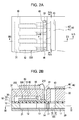
- FIG. 5 is a cross-sectional view of an ink jet recording head according to a second embodiment of the invention.
- FIG. 6 is a cross-sectional view of the ink jet recording head of the second embodiment of the invention.
- FIG. 7 is a schematic view showing an example of the ink jet recording apparatus related to another embodiment of the invention.
- FIG. 1 is an exploded perspective view showing a schematic structure of an ink jet recording head that is one example of a liquid ejecting head related to the embodiment of the invention
- FIG. 2A is a plan view of FIG. 1
- FIG. 2B is a cross-sectional view taken along a line IIB-IIB of the FIG. 2A
- FIG. 3 is a cross-sectional view taken along line a III-III of the FIG. 2B
- FIG. 4A is a cross-sectional view taken along a line IVA-IVA of the FIG. 2A
- FIG. 4B is a cross-sectional view taken along a line IVB-IVB of the FIG. 2A .
- a passage forming substrate 10 that is an example of a first base member is made of a silicon single crystal substrate in which the crystals are oriented to a plane direction ( 110 ).
- An elastic membrane 51 formed of an oxide film is provided on one surface of the passage forming substrate 10 .
- the passage forming substrate 10 includes a plurality of parallel pressure generating chambers 12 partitioned by partition walls 11 which are arranged in a width direction. The upper surface of the pressure generating chambers 12 is provided by the elastic membrane 51 .
- Communicating passages 14 and ink supply paths 13 which communicate with the respective pressure generating chambers 12 which are partitioned by the partition walls 11 are formed at longitudinal end portions of the respective pressure generating chambers 12 in the passage forming substrate 10 .
- a communicating portion 15 communicating with each of communicating passages 14 is formed adjacent to the communicating passages 14 .
- the communicating portion 15 communicates with a reservoir portion 32 of a reservoir forming substrate 30 , described more fully below, in order o form a reservoir 100 which serves as a common ink chamber for the pressure generating chambers 12 .
- the ink supply path 13 has a smaller cross sectional area than that of the pressure generating chamber 12 , which keeps constant flow resistance of ink between the pressure generating chamber 12 and the communicating portion 15 .
- the ink supply paths 13 are formed by narrowing the width of the passage between the reservoir 100 and each pressure generating chamber 12 by extending one side of the partition wall 11 so that the pressure generating chamber 12 has a narrower width.
- the ink supply path 13 is formed by narrowing the width of the passage from one side of the passage, it is also possible to form the ink supply path 13 by narrowing the width of the passage from both sides. Furthermore, the ink supply path 13 can be also formed by narrowing the passage from a thickness direction of the passage instead of by narrowing the width of the passage.
- Each communicating passage 14 is partitioned by the partition walls 11 and is formed by extending the partition walls 11 inwards towards the pressure generating chamber 12 so as to form a space between the ink supply path 13 and the communicating portion 15 .
- the silicon single crystal substrate is used as a material for manufacturing the passage forming substrate 10 in the present embodiment
- the material is not limited to the silicon single crystal substrate, and, for example, glass ceramics can be also used.
- a nozzle plate 20 in which nozzle openings 21 are formed so as to communicate with the respective pressure generating chambers 12 is fixed to a passage surface of the passage forming substrate 10 by use of adhesive agent 17 .
- the nozzle plate 20 is formed of, for example, glass ceramics, silicon single crystal substrate, stainless steel.
- a piezoelectric elements 300 are provided on the passage surface of the passage forming substrate 10 with a vibration plate 50 formed there between.
- the piezoelectric elements 300 and the vibration plate 50 which are driven to vibrate by the piezoelectric elements 300 are referred to collectively as an actuator.
- the elastic membrane 51 is provided on the passage forming substrate 10 as described above.
- An insulation membrane 52 is formed on the elastic membrane 51 .
- the insulation membrane 52 is formed of a material which is different from the elastic membrane 51 , such as, for example, an oxide film formed of titanium oxide (TiOx).
- TiOx titanium oxide
- the elastic membrane 51 and the insulating membrane 52 together constitute the vibration plate 50 .
- the vibration plate 50 is integrally formed with the passage forming substrate 10 instead of adhesion by adhesive agent.
- a partition wall 11 of a pressure generating chamber 12 includes a front end portion 11 a whose width becomes smaller on the side toward the reservoir 100 .
- the front end portion 11 a of the partition wall 11 and the vibration plate 50 form a first angular portion 18
- the vibration plate 50 and a region 11 b which partitions the communicating passage 14 of the partition wall 11 form a second angular portion 19 .
- the front end portion 11 a of the partition wall 11 is not limited so as to have the acute angle as described in the present embodiment, however it represents an end portion facing the reservoir 100 .
- An adhesive agent 17 is continuously applied from the first angular portion 18 to the second angular portion 19 .
- the adhesive agent 17 applied to the first angular portion 18 gives fillet effect, so the adhesive agent 17 relieves stress on the first angular portion 18 .
- the adhesive agent 17 protects the front end portion 11 a . Therefore, even if the front end portion 11 a of the partition wall 11 is stressed by the bending of the nozzle plate 20 , the stress can be relieved to prevent destruction of the front end portion 11 a . Even though the partition wall 11 and the vibration plate 50 are pulled by bending of the nozzle plate 20 , the adhesive agent 17 relieves the stress and prevents occurrence of cracks in the vibration plate 50 .
- a passage partitioned by the adjacent partition walls 11 comprises a communicating passage 14 , and the passage can include the ink supply path 13 .
- the second angular portion 19 is more firmly adhered by the adhesive agent 17 , so that it prevents occurrence of cracks more securely.
- the adhesive agent 17 is continuously applied from the first angular portion 18 to the second angular portion 19 , the first angular portion 18 and the second angular portion 19 are more firmly attached to the adhesive agent 17 , so that the front end portion 11 a and region 11 b of the partition wall 11 can be more securely protected. Even though cracks are formed in the vibration plate 50 in the areas of the first angular portion 18 and the second angular portion 19 , the first angular portion 18 and the second angular portion 19 are covered with the adhesive agent 17 . Therefore, penetration of the ink stored in the reservoir 100 into the cracks of the vibration plate 50 does not occur.
- an ink jet recording head with a high durability can be provided.
- the adhesive agent 17 is made of epoxy resin or the like, and is applied to a surface of the nozzle plate 20 .
- the adhesive agent 17 flows along a boundary portion 11 c , which is a portion between the ink supply path 13 and the communicating passage 14 .
- the adhesive agent reaches the second angular portion 19 , the first angular portion 18 , and the vibration plate 50 disposed at opposite side of the nozzle plate 20 .
- the adhesive agent 17 flows due to a capillary phenomenon until it becomes hardened. That is, the adhesive agent 17 is continuously provided from the boundary portion 11 c to the first angular portion 18 .
- the adhesive agent 17 does not easily detach from the vibration plate 50 as compared with the case where the adhesive agent 17 is provided only at the first angular portion 18 or only from the first angular portion 18 to the second angular portion 19 .
- the angular portion 18 can be more securely protected by the adhesive agent 17 .
- the adhesive agent 17 arrives at the first angular portion 18 by the capillary phenomenon, therefore it is not necessary to separately perform an adhesive agent applying process from the boundary portion 11 c to the first angular portion 18 , so that it is possible to efficiently manufacture the liquid ejecting head, reducing the costs associated with manufacturing.
- the piezoelectric element 300 which is made up of a lower electrode membrane 60 , a piezoelectric layer 70 and an upper electrode membrane 80 , is provided on the vibration plate 50 , which forms a second base member.
- the piezoelectric element 300 includes a portion having the lower electrode membrane 60 , the piezoelectric layer 70 and the upper electrode membrane 80 .
- one electrode of the piezoelectric element 300 is used as a common electrode, while an electrode on the other side of the piezoelectric layer 70 acts an individual electrode for each pressure generating chamber 12 .
- the lower electrode membrane 60 is used as a common electrode of the piezoelectric element 300
- the upper electrode membrane 80 is used as an individual electrode of the piezoelectric element 300
- the piezoelectric element 300 and the vibration plate 50 of the piezoelectric element 300 are referred to collectively as an actuator.
- the vibration plate 50 is not limited to this configuration and other configurations may be used.
- only the lower electrode membrane 60 may function as the vibration plate without the elastic membrane 51 and the insulating membrane 52 .
- the elastic membrane 51 , the insulating membrane 52 and the lower electrode membrane 60 may function as the vibration plate.
- the piezoelectric element 300 itself may substantially function as the vibration plate.
- the piezoelectric layer 70 is made of a piezoelectric material, which has an electro-mechanical transduction function, and is more particularly made of a ferroelectric material having a perovskite structure.
- the piezoelectric layer is provided on the lower electrode membrane 60 . It is preferable that the piezoelectric layer 70 is formed from, for example, the ferroelectric material such as lead zirconate titanate (PZT), or the ferroelectric material including metal oxide such as niobium oxide (Nb 2 O 5 ), nickel oxide (NiO), magnesium oxide (MgO).
- PZT lead zirconate titanate
- MgO magnesium oxide
- lead titanate (PbTiO), lead zirconate titanate (Pb(Zr, Ti) O), lead zirconate (PbZrO), lanthanum lead titanate ((Pb, La), TiO), lanthanum lead titanate zirconate ((Pb, La) (Zr, Ti) O) and lead titanate zirconate niobate magnesium (Pb(Zr, Ti) (Mg, Nb) O) or the like may be used.
- Lead electrodes 90 are connected to the corresponding upper electrode membrane 80 that acts as the individual electrode of the piezoelectric element 300 .
- the lead electrode 90 is made of, for example, gold (Au), and extends from the area near the end portion of the ink supply path 13 to the insulating membrane 52 .
- a reservoir forming substrate 30 having a reservoir portion 32 which constitutes at least a portion of the reservoir 100 is adhered with intervention of adhesive agent 35 on the passage forming substrate 10 which has the piezoelectric element 300 formed thereon, that is, on the lower electrode membrane 60 , the insulating membrane 52 and the lead electrode 90 .
- the reservoir portion 32 passes through the reservoir forming substrate 30 in the thickness direction and extends in the width direction of the pressure generating chambers 12 , and as described above, communicates with the communicating portion 15 of the passage forming substrate 10 .
- the reservoir portion 32 and the communicating portion 15 together comprise the reservoir 100 , which acts as a common ink chamber of the pressure generating chambers 12 .
- a piezoelectric element holding portion 31 with a sufficient space so as not to hinder movement of the piezoelectric element 300 is formed in a region of the reservoir forming substrate 30 facing the piezoelectric element 300 . As long as the piezoelectric element holding portion 31 includes enough space so as not hinder the movement of the piezoelectric element 300 , it does not matter whether the space is sealed or not.
- a material having approximately the same coefficient of thermal expansion with that of the passage forming substrate 10 such as glass or ceramic materials is used to form the reservoir forming substrate 30 .
- a silicon single crystal substrate of a material which is identical to that of the passage forming substrate 10 is used.
- the reservoir forming substrate 30 also includes a through-hole 33 that extends through the reservoir forming substrate 30 in the thickness direction. An end portion of the lead electrode 90 extending from the respective piezoelectric elements 300 is exposed in the through-hole 33 .
- a driving circuit 200 for driving the piezoelectric elements 300 is fixed on the reservoir forming substrate 30 .
- the driving circuit 200 for example, a circuit board or a semiconductor integrated circuit (IC) may be used.
- the driving circuit 200 is electrically connected to the lead electrode 90 by a connection wiring 210 formed of a conductive wire such as a bonding wire.
- a compliance substrate 40 which includes a sealing membrane 41 and a fixing plate 42 , is adhered on the reservoir forming substrate 30 a .
- the sealing membrane 41 is formed of a material with a low rigidity and which has a flexibility (e.g., polyphenylene sulfide (PPS) film), and seals one surface of the reservoir portion 32 .
- the fixed plate 42 is formed of a hard material, such as metal (for example, stainless steel (SUS)). Since a region of the fixed plate 42 facing the reservoir 100 forms an opening 43 , one side surface of the reservoir 100 is sealed by the flexible sealing membrane 41 .
- ink is introduced through an ink inlet port connected to an external ink supply unit (not shown), and then, the inside portion from the reservoir 100 to the nozzle orifice 21 is filled with the ink. Then, according to a recording signal from the driving circuit 200 , a voltage is applied between the lower electrode membrane 60 and the upper electrode membrane 80 corresponding to each of the pressure generating chambers 12 . Accordingly, the elastic membrane 51 , the insulating membrane 52 , the lower electrode membrane 60 and the piezoelectric layer 70 are bent, so that the pressure in the respective pressure generating chambers 12 increases so as to eject ink droplets from the nozzle opening 21 .
- the ink jet recording head has a piezoelectric element 300 which is capable of bending, but the invention is not limited to this embodiment, and, for example, it can be applied to a vertical vibration type ink jet recording head.
- FIG. 5 is a cross-sectional view of an ink jet recording head related to a second embodiment
- FIG. 6 is a cross-sectional view taken along a line VI-VI of the FIG. 5 .
- an ink jet recording head of the second embodiment includes a passage forming substrate 112 having a plurality of pressure generating chambers 111 , a nozzle plate 114 having a plurality of nozzle openings 113 which communicate with the respective pressure generating chambers 111 , a vibration plate 115 disposed on a surface of the passage forming substrate 112 opposite to the nozzle plate 114 , a piezoelectric element unit 117 having piezoelectric elements 116 disposed on the vibration plate 115 at a region corresponding to the respective pressure generating chambers 111 , and a head case 119 which is fixed to the vibration plate 115 and which includes a receiving portion 118 for receiving the piezoelectric element unit 117 .
- a plurality of pressure generating chambers 111 which are partitioned by partition walls 150 are arranged in parallel to the width direction on one surface of the passage forming substrate 112 which forms a first base member.
- the pressure generating chambers 111 are arranged in parallel in the passage forming substrate 112 .
- a reservoir 121 for supplying ink to the respective pressure generating chambers 111 is formed in the thickness direction of the passage forming substrate 112 in an area adjacent to the pressure generating chambers 111 .
- the reservoir 121 communicates with the respective pressure generating chambers 111 via an ink supply path 122 .
- the ink supply path 122 is formed to have a narrower width than that of the pressure generating chambers 111 , and thus the flow resistance of the ink flowing from the reservoir 121 into the pressure generating chambers 111 can be kept constant.
- Island-shaped wall portions 151 extending to the ink flow are provided in the corresponding ink supply path 122 of the passage forming substrate 112 .
- area of ink passage in the ink supply path 122 becomes narrower, so it can prevent pressure reduction in the pressure generating chambers 111 .
- a nozzle communicating hole 123 extending through the passage forming substrate 112 is adjacent to the pressure generating chamber 111 opposite to the reservoir 121 .
- the reservoir 121 communicates with an ink introduction path 141 formed to penetrate the head case 119 in the width direction.
- the ink introduction path 141 is a passage that introduces ink from an ink cartridge (not shown) to the reservoir 121 .
- a liquid passage constituted by the reservoir 121 , the ink supply path 122 , the pressure generating chamber 111 and the nozzle communicating hole 123 is formed on the passage forming substrate 112 .
- the passage forming substrate 112 is made of a silicon single crystal substrate, and the pressure generating chambers 111 provided on the passage forming substrate 112 are formed by etching the passage forming substrate 112 .
- the nozzle plate 114 having the nozzle openings 113 formed therein is adhered by adhesive agent, and the respective nozzle openings 113 communicate with the respective pressure generating chamber by way of the nozzle communicating hole 123 formed in the passage forming substrate 114 .
- the vibration plate 115 is adhered to the opposite surface of the passage forming substrate 112 , that is, the orifice surface of the pressure generating chamber 111 , so each pressure generating chamber 111 is sealed by the vibration plate 115 .
- the vibration plate 115 comprises a composite plate 125 which is made up of an elastic membrane 124 and a support plate 125 .
- the elastic membrane 124 is formed of, for example, an elastic member like resin film.
- the support plate 125 is formed of, for example, a metallic material.
- the elastic membrane 124 side is adhered to the passage forming substrate 112 .
- the elastic membrane 124 is formed of a polyphenylene sulfide (PPS) film, and the support plate 125 is formed of stainless steel (SUS).
- An island-shaped portion 126 in contact with a front end portion of the piezoelectric element 116 is provided within an area of the vibration plate 115 facing the respective pressure generating chamber 111 .
- a thin-walled member 127 having a width smaller than those of other members is formed in an area of the vibration plate 115 facing the circumferential region of the respective pressure generating chamber 111 , and the island-shaped portions 126 are provided on the thin-walled member 127 .
- a compliance portion 128 of the thin-walled member which is formed by etching the support plate 125 and is substantially made up only of a elastic membrane, is provided in the region of the vibration plate 115 facing the reservoir 121 .
- the compliance portion 128 absorbs the changed pressure by transformation of the elastic membrane 124 , so it keeps the pressure in the reservoir 121 to be constant.
- the vibration plate 115 and a front end portion 150 a of the partition wall 150 disposed at the side of the reservoir 121 form a first angular portion 18 A, and the vibration plate 115 and a region 150 b in the partition wall 150 partitioning the ink supply path 122 form a second angular portion 19 A.
- the adhesive agent 17 A is continuously provided from the first angular portion 18 A to the second angular portion 19 A.
- the adhesive agent 17 A provided on the first angular portion 18 A gives the same effect that a fillet of the adhesive agent 17 A is formed on the first angular portion 18 A, so that it relieves stress on the first angular portion 18 A.
- the front end portion 150 a of the partition wall 150 has a narrow width and is vulnerable to stress destruction, the front end portion 150 a is protected by the adhesive agent 17 A. Therefore, even if the front end portion 150 a of the partition wall 150 is stressed by bending of the nozzle plate 114 , the stress is relieved to prevent destruction of the front end portion 150 a . Even though the partition wall 150 and the vibration plate 115 are pulled by the bending of the nozzle plate 114 , the adhesive agent 17 A relieves the stress and prevents occurrence of cracks in the vibration plate 115 .
- the adhesive agent 17 A is also provided to the second angle portion 19 A, so that it prevents occurrence of cracks in a region 150 b partitioning the ink supply path 122 of the partition wall 150 or in the vibration plate 115 of at a vicinity of the region 150 b.
- the adhesive agent 17 A is continuously provided from the first angular portion 18 a to the second angular portion 19 A, and thus the first angular portion 18 a and the second angular portion 19 A are more strongly adhered by the adhesive agent 17 A, so the region 150 b and the front end portion 150 a of the partition wall 150 can be more securely protected.
- the first angular portion 18 A and the second angular portion 19 a are covered with the adhesive agent 17 A, so ink is prevented from entering into cracks of the vibration plate 115 .
- the adhesive agent 17 A is provided to an angular portion 152 formed by the island-shaped wall portion 151 and the vibration plate 115 . According to this, it is possible to prevent cracks in a front end portion 151 a of the island-shaped wall portion 151 or in a region 151 b of the island-shaped wall portion 151 facing the partition wall 150 , and also possible to prevent cracks in the vibration plate 115 near the front end portion 151 a and the region 151 b.
- the adhesive agent 17 A is made of, for example, epoxy resin or the like, and is applied to one surface of the nozzle plate 114 .
- the adhesive agent 17 A flows from a front end portion 150 c of the partition wall 150 to the vibration plate 115 disposed at opposite side.
- the adhesive agent 17 A reaches the first angular portion 18 A and the second angular portion 19 A, and then is hardened. That is, the adhesive agent 17 A is continuously provided from the end portion 150 c to the second angular portion 19 .
- the adhesive agent 17 A is more consistently applied from the vibration plate 115 as compared with the case where the adhesive agent 17 A is provided only at the first angular portion 18 A or only from the first angular portion 18 A to the second angular portion 19 A.
- the first angular portion 18 A and the second angular portion 19 A can be more securely protected by the adhesive agent 17 A.
- the adhesive agent 17 A arrives at the first angular portion 18 A by the capillary phenomenon, therefore it is not necessary to perform a separate adhesive agent applying process from the end portion 150 c to the first angular portion 18 A, so the liquid ejecting head can be more efficiently manufactured, providing a lower cost liquid ejecting head.
- a front end of an active region of the piezoelectric element 116 constituting the piezoelectric element unit 117 is fixed, so as to be in contact with the island-shaped portion 126 of the vibration plate 115 .
- the piezoelectric element 116 that is a pressure generating device for generating pressure for discharging ink droplet is integrally formed as the piezoelectric element unit 117 . That is, a piezoelectric element forming member 132 is formed by vertically and alternately forming layers of a piezoelectric material 129 and electrode forming materials 130 , 131 . Each piezoelectric element 116 is formed by separating the piezoelectric element forming member 132 in the form of comb teeth corresponding to the respective pressure generating chambers 111 . In other words, in the present embodiment, a plurality of the piezoelectric elements 116 are integrally formed.
- the piezoelectric element unit 117 comprises the piezoelectric element 116 (or the piezoelectric element forming member 132 ), the fixed substrate 133 , and the circuit substrate 135 .
- the front end of the piezoelectric element 116 of the piezoelectric element unit 117 is fixed so as to be in contact with the island-shaped portion 126 of the vibration plate 115 .
- the head case 119 is fixed to the vibration plate 115 , and the piezoelectric element unit 117 is received inside the receiving portion 118 of the head case 119 .
- the fixing substrate 133 having the piezoelectric element 116 fixed thereto is fixed to the head case 119 opposite to the piezoelectric element 116 .
- a plurality of the receiving portions 118 receiving the piezoelectric element unit 117 ( FIG. 5 shows one receiving portion) are installed, and one piezoelectric element unit 117 is disposed in one receiving portion 118 .
- a wiring substrate 137 is fixed in the head case 119 .
- the wiring substrate 137 includes a plurality of conductive pads 136 to which the wirings 134 of the circuit substrate 135 are connected respectively.
- the receiving portion 118 of the head case 119 is substantially closed by the wiring substrate 137 .
- the wiring substrate 137 includes a slit-shaped opening 138 formed in a region facing the receiving portion 118 of the head case 119 . Therefore, the circuit substrate 135 is provided to appear outside the receiving portion 118 from the opening portion 138 of the wiring substrate 137 .
- the circuit substrate 135 comprising the piezoelectric element unit 117 includes a flexible printed circuit (FPS) substrate to which a driving IC (not shown) for driving the piezoelectric element 116 is provided, such as a tape carrier package (TCP), a chip on film (COF) and a flexible flat cable (FFC) or the like.
- the base end portion of the respective wiring 134 of the circuit substrate 135 is connected to the electrode forming materials 130 , 131 which comprise the piezoelectric element 116 by means of, for example, a solder, an anisotropic conductive material or the like.
- the front end of the respective wiring 134 of the circuit substrate 135 is connected to the conductive pads 136 of the wiring substrate 137 .
- the wirings 134 are connected to the conductive pads 136 of the wiring substrate 137 respectively by soldering (not shown).
- the ink jet recording head changes the volume of the corresponding pressure generating chamber 111 by driving the piezoelectric element 116 and the vibration plate 115 , causing an ink droplet to be discharged from a predetermined nozzle opening 113 .
- ink is supplied to the reservoir 121 from an ink cartridge (not shown)
- ink is distributed to corresponding pressure generating chamber 111 by way of the ink supply path 122 .
- the piezoelectric element 116 is contracted.
- the vibration plate 115 is moved with the piezoelectric element 116 , causing the volume of the pressure generating chamber 111 can be increased, as a result, ink is drawn to the pressure generating chamber 111 .
- the adhesive agents 17 , 17 A are continuously provided to the nozzle plates 20 , 114 and the passage forming substrates 10 , 112
- the adhesive agents 17 , 17 A can be separately provided. That is, after the adhesive agents 17 , 17 A are applied to the first angular portions 18 , 18 A and the second angular portions 19 , 19 A respectively, the nozzle plates 20 , 114 can be adhered to the passage forming substrates 10 , 112 .
- the ink jet recording head of the above-mentioned embodiment constitutes a part of a recording head unit including an ink passage that communicates with an ink cartridge and the like, and is disposed in an ink jet type recording apparatus.
- FIG. 7 is a schematic view showing an example of the ink jet type recording apparatus.
- ink cartridges 2 A and 2 B serve as an ink supply unit and are detachably installed to recording head units 1 A and 1 B having ink jet recording heads.
- a carriage 3 in which the recording head units 1 A and 1 B is installed is provided such that the carriage 3 can move freely to axial direction of a carriage axis 5 disposed in a main body 4 of the apparatus.
- the recording head units 1 A and 1 B for example, discharge a black ink composition and a color ink composition, respectively.
- a driving force of a driving motor 6 is transmitted to the carriage 3 by intervention of a plurality of gears (not shown) and a timing belt 7 , so that the carriage 3 having the recording head units 1 A and 1 B mounted thereon moves along the carriage axis 5 .
- a platen 8 is disposed along the carriage axis 5 in the main body 4 of the apparatus, a recording sheet S, which is a recording medium fed by a sheet feeding roller (not shown), is transported on the platen 8 .
- the basic configuration of the liquid ejecting head can also be applied not only to general liquid ejecting heads, but also to apparatuses ejecting liquid other than ink.
- the liquid ejecting head includes, for example, various recording heads used in image recording apparatuses such as a printers or the like, color material ejecting heads used for manufacturing a color filter such as a liquid crystal display or the like, an electrode material ejecting heads used for forming electrode of an organic EL display, an electric field display or the like, and a bio organic substance ejection heads used for manufacturing a bio-chip.
Abstract
Description
Claims (5)
Applications Claiming Priority (2)
| Application Number | Priority Date | Filing Date | Title |
|---|---|---|---|
| JP2008323323A JP2010143098A (en) | 2008-12-19 | 2008-12-19 | Liquid jet head and liquid jet apparatus |
| JP2008-323323 | 2008-12-19 |
Publications (2)
| Publication Number | Publication Date |
|---|---|
| US20100156999A1 US20100156999A1 (en) | 2010-06-24 |
| US8152281B2 true US8152281B2 (en) | 2012-04-10 |
Family
ID=42265421
Family Applications (1)
| Application Number | Title | Priority Date | Filing Date |
|---|---|---|---|
| US12/635,960 Active 2030-10-06 US8152281B2 (en) | 2008-12-19 | 2009-12-11 | Liquid ejecting head and liquid ejecting apparatus |
Country Status (2)
| Country | Link |
|---|---|
| US (1) | US8152281B2 (en) |
| JP (1) | JP2010143098A (en) |
Citations (5)
| Publication number | Priority date | Publication date | Assignee | Title |
|---|---|---|---|---|
| JP2007026125A (en) | 2005-07-19 | 2007-02-01 | Hitachi Ltd | Recording and reproducing apparatus |
| US7530673B2 (en) * | 2005-08-11 | 2009-05-12 | Seiko Epson Corporation | Actuator device, liquid-jet head and liquid-jet apparatus |
| US7712878B2 (en) * | 2007-03-29 | 2010-05-11 | Seiko Epson Corporation | Liquid ejecting head and method for manufacturing the same |
| US7789495B2 (en) * | 2006-08-02 | 2010-09-07 | Seiko Epson Corporation | Liquid ejection head and liquid ejection apparatus |
| US7909439B2 (en) * | 2008-03-24 | 2011-03-22 | Seiko Epson Corporation | Liquid ejecting head and liquid ejecting apparatus |
Family Cites Families (2)
| Publication number | Priority date | Publication date | Assignee | Title |
|---|---|---|---|---|
| JP3555653B2 (en) * | 1998-09-30 | 2004-08-18 | セイコーエプソン株式会社 | Ink jet recording head and method of manufacturing the same |
| JP4883291B2 (en) * | 2006-10-17 | 2012-02-22 | セイコーエプソン株式会社 | Liquid ejecting head and liquid ejecting apparatus |
-
2008
- 2008-12-19 JP JP2008323323A patent/JP2010143098A/en not_active Withdrawn
-
2009
- 2009-12-11 US US12/635,960 patent/US8152281B2/en active Active
Patent Citations (5)
| Publication number | Priority date | Publication date | Assignee | Title |
|---|---|---|---|---|
| JP2007026125A (en) | 2005-07-19 | 2007-02-01 | Hitachi Ltd | Recording and reproducing apparatus |
| US7530673B2 (en) * | 2005-08-11 | 2009-05-12 | Seiko Epson Corporation | Actuator device, liquid-jet head and liquid-jet apparatus |
| US7789495B2 (en) * | 2006-08-02 | 2010-09-07 | Seiko Epson Corporation | Liquid ejection head and liquid ejection apparatus |
| US7712878B2 (en) * | 2007-03-29 | 2010-05-11 | Seiko Epson Corporation | Liquid ejecting head and method for manufacturing the same |
| US7909439B2 (en) * | 2008-03-24 | 2011-03-22 | Seiko Epson Corporation | Liquid ejecting head and liquid ejecting apparatus |
Also Published As
| Publication number | Publication date |
|---|---|
| JP2010143098A (en) | 2010-07-01 |
| US20100156999A1 (en) | 2010-06-24 |
Similar Documents
| Publication | Publication Date | Title |
|---|---|---|
| US9533501B2 (en) | Liquid jet head and a liquid jet apparatus including a piezoelectric material having an upper electrode and a lower electrode | |
| US8152283B2 (en) | Liquid-jet head and liquid-jet apparatus | |
| KR20070099451A (en) | Actuator device, liquid-jet head and liquid-jet apparatus | |
| US20090289999A1 (en) | Liquid ejecting head and liquid ejecting apparatus including the same | |
| JP2009234254A (en) | Liquid jet head and liquid jet apparatus | |
| US8197035B2 (en) | Actuator device and liquid ejecting head including the same | |
| US7891782B2 (en) | Liquid injecting head, method of manufacturing liquid injecting head, and liquid injecting device | |
| JP4614070B2 (en) | Liquid ejecting head and liquid ejecting apparatus | |
| JP4508595B2 (en) | Liquid ejecting head, manufacturing method thereof, and liquid ejecting apparatus | |
| US7914128B2 (en) | Liquid ejecting head, piezoelectric element, and liquid ejecting apparatus | |
| JP2007216474A (en) | Liquid jet head and liquid jet device | |
| JP5218730B2 (en) | Liquid ejecting head and liquid ejecting apparatus | |
| JP2007050551A (en) | Liquid jetting head and liquid jetting apparatus | |
| JP2006248166A (en) | Liquid ejection head and liquid ejection device | |
| JP2006218776A (en) | Liquid injection head and liquid injection apparatus | |
| US8152281B2 (en) | Liquid ejecting head and liquid ejecting apparatus | |
| CN109484030B (en) | Liquid ejecting head, liquid ejecting apparatus, and piezoelectric device | |
| JP2012218251A (en) | Liquid jet head, and liquid jet apparatus | |
| JP2013111819A (en) | Liquid injection head and liquid injection device | |
| US7798614B2 (en) | Inkjet head | |
| JP2007118265A (en) | Liquid jetting head, and liquid jetting device | |
| JP7006060B2 (en) | Liquid injection head, liquid injection device, and piezoelectric device | |
| JP4484821B2 (en) | Liquid ejecting head and liquid ejecting apparatus | |
| JP5485208B2 (en) | Inkjet head | |
| JP2010149376A (en) | Liquid injection head and liquid injection device |
Legal Events
| Date | Code | Title | Description |
|---|---|---|---|
| AS | Assignment |
Owner name: SEIKO EPSON CORPORATION,JAPAN Free format text: ASSIGNMENT OF ASSIGNORS INTEREST;ASSIGNOR:MATSUMOTO, YASUYUKI;REEL/FRAME:023641/0215 Effective date: 20091126 Owner name: SEIKO EPSON CORPORATION, JAPAN Free format text: ASSIGNMENT OF ASSIGNORS INTEREST;ASSIGNOR:MATSUMOTO, YASUYUKI;REEL/FRAME:023641/0215 Effective date: 20091126 |
|
| STCF | Information on status: patent grant |
Free format text: PATENTED CASE |
|
| FEPP | Fee payment procedure |
Free format text: PAYOR NUMBER ASSIGNED (ORIGINAL EVENT CODE: ASPN); ENTITY STATUS OF PATENT OWNER: LARGE ENTITY |
|
| FPAY | Fee payment |
Year of fee payment: 4 |
|
| MAFP | Maintenance fee payment |
Free format text: PAYMENT OF MAINTENANCE FEE, 8TH YEAR, LARGE ENTITY (ORIGINAL EVENT CODE: M1552); ENTITY STATUS OF PATENT OWNER: LARGE ENTITY Year of fee payment: 8 |
|
| MAFP | Maintenance fee payment |
Free format text: PAYMENT OF MAINTENANCE FEE, 12TH YEAR, LARGE ENTITY (ORIGINAL EVENT CODE: M1553); ENTITY STATUS OF PATENT OWNER: LARGE ENTITY Year of fee payment: 12 |