US8126049B2 - Method and a device for transmitting images - Google Patents
Method and a device for transmitting images Download PDFInfo
- Publication number
- US8126049B2 US8126049B2 US12/137,975 US13797508A US8126049B2 US 8126049 B2 US8126049 B2 US 8126049B2 US 13797508 A US13797508 A US 13797508A US 8126049 B2 US8126049 B2 US 8126049B2
- Authority
- US
- United States
- Prior art keywords
- images
- information
- network
- over
- image
- Prior art date
- Legal status (The legal status is an assumption and is not a legal conclusion. Google has not performed a legal analysis and makes no representation as to the accuracy of the status listed.)
- Expired - Fee Related, expires
Links
Images


Classifications
-
- H—ELECTRICITY
- H04—ELECTRIC COMMUNICATION TECHNIQUE
- H04N—PICTORIAL COMMUNICATION, e.g. TELEVISION
- H04N21/00—Selective content distribution, e.g. interactive television or video on demand [VOD]
- H04N21/20—Servers specifically adapted for the distribution of content, e.g. VOD servers; Operations thereof
- H04N21/23—Processing of content or additional data; Elementary server operations; Server middleware
- H04N21/234—Processing of video elementary streams, e.g. splicing of video streams, manipulating MPEG-4 scene graphs
- H04N21/2343—Processing of video elementary streams, e.g. splicing of video streams, manipulating MPEG-4 scene graphs involving reformatting operations of video signals for distribution or compliance with end-user requests or end-user device requirements
- H04N21/23439—Processing of video elementary streams, e.g. splicing of video streams, manipulating MPEG-4 scene graphs involving reformatting operations of video signals for distribution or compliance with end-user requests or end-user device requirements for generating different versions
-
- H—ELECTRICITY
- H04—ELECTRIC COMMUNICATION TECHNIQUE
- H04N—PICTORIAL COMMUNICATION, e.g. TELEVISION
- H04N19/00—Methods or arrangements for coding, decoding, compressing or decompressing digital video signals
- H04N19/10—Methods or arrangements for coding, decoding, compressing or decompressing digital video signals using adaptive coding
- H04N19/102—Methods or arrangements for coding, decoding, compressing or decompressing digital video signals using adaptive coding characterised by the element, parameter or selection affected or controlled by the adaptive coding
- H04N19/103—Selection of coding mode or of prediction mode
- H04N19/114—Adapting the group of pictures [GOP] structure, e.g. number of B-frames between two anchor frames
-
- H—ELECTRICITY
- H04—ELECTRIC COMMUNICATION TECHNIQUE
- H04N—PICTORIAL COMMUNICATION, e.g. TELEVISION
- H04N19/00—Methods or arrangements for coding, decoding, compressing or decompressing digital video signals
- H04N19/10—Methods or arrangements for coding, decoding, compressing or decompressing digital video signals using adaptive coding
- H04N19/134—Methods or arrangements for coding, decoding, compressing or decompressing digital video signals using adaptive coding characterised by the element, parameter or criterion affecting or controlling the adaptive coding
- H04N19/164—Feedback from the receiver or from the transmission channel
-
- H—ELECTRICITY
- H04—ELECTRIC COMMUNICATION TECHNIQUE
- H04N—PICTORIAL COMMUNICATION, e.g. TELEVISION
- H04N19/00—Methods or arrangements for coding, decoding, compressing or decompressing digital video signals
- H04N19/10—Methods or arrangements for coding, decoding, compressing or decompressing digital video signals using adaptive coding
- H04N19/169—Methods or arrangements for coding, decoding, compressing or decompressing digital video signals using adaptive coding characterised by the coding unit, i.e. the structural portion or semantic portion of the video signal being the object or the subject of the adaptive coding
- H04N19/17—Methods or arrangements for coding, decoding, compressing or decompressing digital video signals using adaptive coding characterised by the coding unit, i.e. the structural portion or semantic portion of the video signal being the object or the subject of the adaptive coding the unit being an image region, e.g. an object
- H04N19/172—Methods or arrangements for coding, decoding, compressing or decompressing digital video signals using adaptive coding characterised by the coding unit, i.e. the structural portion or semantic portion of the video signal being the object or the subject of the adaptive coding the unit being an image region, e.g. an object the region being a picture, frame or field
-
- H—ELECTRICITY
- H04—ELECTRIC COMMUNICATION TECHNIQUE
- H04N—PICTORIAL COMMUNICATION, e.g. TELEVISION
- H04N19/00—Methods or arrangements for coding, decoding, compressing or decompressing digital video signals
- H04N19/10—Methods or arrangements for coding, decoding, compressing or decompressing digital video signals using adaptive coding
- H04N19/169—Methods or arrangements for coding, decoding, compressing or decompressing digital video signals using adaptive coding characterised by the coding unit, i.e. the structural portion or semantic portion of the video signal being the object or the subject of the adaptive coding
- H04N19/177—Methods or arrangements for coding, decoding, compressing or decompressing digital video signals using adaptive coding characterised by the coding unit, i.e. the structural portion or semantic portion of the video signal being the object or the subject of the adaptive coding the unit being a group of pictures [GOP]
-
- H—ELECTRICITY
- H04—ELECTRIC COMMUNICATION TECHNIQUE
- H04N—PICTORIAL COMMUNICATION, e.g. TELEVISION
- H04N19/00—Methods or arrangements for coding, decoding, compressing or decompressing digital video signals
- H04N19/60—Methods or arrangements for coding, decoding, compressing or decompressing digital video signals using transform coding
- H04N19/61—Methods or arrangements for coding, decoding, compressing or decompressing digital video signals using transform coding in combination with predictive coding
-
- H—ELECTRICITY
- H04—ELECTRIC COMMUNICATION TECHNIQUE
- H04N—PICTORIAL COMMUNICATION, e.g. TELEVISION
- H04N21/00—Selective content distribution, e.g. interactive television or video on demand [VOD]
- H04N21/20—Servers specifically adapted for the distribution of content, e.g. VOD servers; Operations thereof
- H04N21/23—Processing of content or additional data; Elementary server operations; Server middleware
- H04N21/238—Interfacing the downstream path of the transmission network, e.g. adapting the transmission rate of a video stream to network bandwidth; Processing of multiplex streams
- H04N21/23805—Controlling the feeding rate to the network, e.g. by controlling the video pump
-
- H—ELECTRICITY
- H04—ELECTRIC COMMUNICATION TECHNIQUE
- H04N—PICTORIAL COMMUNICATION, e.g. TELEVISION
- H04N21/00—Selective content distribution, e.g. interactive television or video on demand [VOD]
- H04N21/20—Servers specifically adapted for the distribution of content, e.g. VOD servers; Operations thereof
- H04N21/25—Management operations performed by the server for facilitating the content distribution or administrating data related to end-users or client devices, e.g. end-user or client device authentication, learning user preferences for recommending movies
- H04N21/262—Content or additional data distribution scheduling, e.g. sending additional data at off-peak times, updating software modules, calculating the carousel transmission frequency, delaying a video stream transmission, generating play-lists
- H04N21/26208—Content or additional data distribution scheduling, e.g. sending additional data at off-peak times, updating software modules, calculating the carousel transmission frequency, delaying a video stream transmission, generating play-lists the scheduling operation being performed under constraints
- H04N21/26216—Content or additional data distribution scheduling, e.g. sending additional data at off-peak times, updating software modules, calculating the carousel transmission frequency, delaying a video stream transmission, generating play-lists the scheduling operation being performed under constraints involving the channel capacity, e.g. network bandwidth
-
- H—ELECTRICITY
- H04—ELECTRIC COMMUNICATION TECHNIQUE
- H04N—PICTORIAL COMMUNICATION, e.g. TELEVISION
- H04N21/00—Selective content distribution, e.g. interactive television or video on demand [VOD]
- H04N21/20—Servers specifically adapted for the distribution of content, e.g. VOD servers; Operations thereof
- H04N21/25—Management operations performed by the server for facilitating the content distribution or administrating data related to end-users or client devices, e.g. end-user or client device authentication, learning user preferences for recommending movies
- H04N21/262—Content or additional data distribution scheduling, e.g. sending additional data at off-peak times, updating software modules, calculating the carousel transmission frequency, delaying a video stream transmission, generating play-lists
- H04N21/26208—Content or additional data distribution scheduling, e.g. sending additional data at off-peak times, updating software modules, calculating the carousel transmission frequency, delaying a video stream transmission, generating play-lists the scheduling operation being performed under constraints
- H04N21/26233—Content or additional data distribution scheduling, e.g. sending additional data at off-peak times, updating software modules, calculating the carousel transmission frequency, delaying a video stream transmission, generating play-lists the scheduling operation being performed under constraints involving content or additional data duration or size, e.g. length of a movie, size of an executable file
-
- H—ELECTRICITY
- H04—ELECTRIC COMMUNICATION TECHNIQUE
- H04N—PICTORIAL COMMUNICATION, e.g. TELEVISION
- H04N21/00—Selective content distribution, e.g. interactive television or video on demand [VOD]
- H04N21/60—Network structure or processes for video distribution between server and client or between remote clients; Control signalling between clients, server and network components; Transmission of management data between server and client, e.g. sending from server to client commands for recording incoming content stream; Communication details between server and client
- H04N21/63—Control signaling related to video distribution between client, server and network components; Network processes for video distribution between server and clients or between remote clients, e.g. transmitting basic layer and enhancement layers over different transmission paths, setting up a peer-to-peer communication via Internet between remote STB's; Communication protocols; Addressing
- H04N21/643—Communication protocols
- H04N21/64322—IP
-
- H—ELECTRICITY
- H04—ELECTRIC COMMUNICATION TECHNIQUE
- H04N—PICTORIAL COMMUNICATION, e.g. TELEVISION
- H04N21/00—Selective content distribution, e.g. interactive television or video on demand [VOD]
- H04N21/80—Generation or processing of content or additional data by content creator independently of the distribution process; Content per se
- H04N21/83—Generation or processing of protective or descriptive data associated with content; Content structuring
- H04N21/845—Structuring of content, e.g. decomposing content into time segments
- H04N21/8453—Structuring of content, e.g. decomposing content into time segments by locking or enabling a set of features, e.g. optional functionalities in an executable program
Definitions
- the present invention concerns a method and a device for transmitting images. It applies, in particular, to the transmission of a video over a network at variable rate.
- the images of a compressed video transmitted over a network may arrive at irregular intervals of time.
- the images are sometimes displayed with temporal shifts liable to give rise to an unpleasant visual effect: an unpleasant impression of jerkiness is perceived.
- the management of the CPU resources and memory of the client is easier when the images arrive at a regular interval.
- INTRA images are classic examples in the context of an MPEG type video compression. INTRA images do not use the temporal prediction module (motion estimation by block matching). INTRA images are more difficult to compress and their size is generally 4 to 5 times the size of an INTER image (for the same visual quality). If the bandwidth is too low to ensure the transmission of such an image during the time interval between two images, there is a risk of late arrival of an INTRA image at the client. On account of this, an unpleasant visual effect may occur.
- a means for solving this problem is to possess a buffer memory large enough at the recipient so as to take up possible transmission delays.
- some clients/recipients do not possess a buffer memory of sufficient size to store the data of images prior to their display.
- Even if a recipient possesses a sufficient buffer memory events may occur that empty that buffer memory, such as a temporary interruption of the sending of the data by the server. The jerky effect then occurs.
- a buffer memory is not appropriate because it necessarily introduces lag, that is to say a delay between the reception of the information representing the image and its display after decoding.
- the present invention aims to mitigate these drawbacks.
- the present invention makes it possible to synchronize the sending of the heaviest images of the video (typically the INTRA images) with times for which the quantity of information sent according to the network protocol (for example TCP or TFRC) is greatest.
- the network protocol for example TCP or TFRC
- the present invention concerns a method of transmission of a datastream representing a sequence of images over a network in which the quantity of information that may be sent per unit of time varies substantially cyclically, said transmission extending over a plurality of cycles, that comprises:
- the present invention concerns a method of transmission of a datastream representing a sequence of images over a network in which the quantity of information that may be sent per unit of time varies substantially cyclically, said transmission extending over a plurality of cycles, that comprises:
- a period of cyclical variation of the quantity of information that may be sent over the network is determined.
- extrema of information quantity that may be sent over the network are determined.
- the determination of the period of substantially cyclical variation is automatic and adaptive.
- a quantity of information is determined that is kept in a memory and that remains to be transmitted over the network.
- an image to code is selected with a compression rate lower than the compression rate of the images surrounding it, the transmission of the images being carried out in their chronological order, such that the transmission of the coded image, over the network, corresponds to a time for which the quantity of information that may be sent per unit of time over the network is greatest.
- a step is carried out of coding at least one image with a plurality of coding modes representing the same image by different quantities of information.
- a step is carried out of coding the same succession of a plurality of images into a plurality of bitstreams, each bitstream representing that succession of images with a specific image which is represented with a coding mode representing a lower compression rate than the other images of said succession of images.
- the bitstream is transmitted for which the specific image corresponds to a time for which the quantity of information that may be sent per unit of time over the network is greatest.
- the position is determined, in time, of its transmission over the network in case that single image is coded with a coding mode of lower compression rate than the other images of said plurality of images and the image is selected for which said position corresponds to a time for which the quantity of information that may be sent per unit of time over the network is greatest, in order for the selected image to be coded with said coding mode of least compression rate.
- the present invention concerns a device for transmission of a datastream representing a sequence of images over a network in which the quantity of information that may be sent per unit of time varies substantially cyclically, said transmission extending over a plurality of cycles, that comprises:
- the present invention concerns a computer program loadable into a computer system, said program containing instructions enabling the implementation of the method of transmitting images as succinctly set forth above.
- the present invention concerns an information carrier readable by a computer or a microprocessor, removable or not, storing instructions of a computer program, characterized in that it enables the implementation of the method of transmitting images as succinctly set forth above.
- FIG. 1 is a diagrammatic representation of an application of the present invention
- FIG. 2 is a diagrammatic representation of a cyclical bandwidth
- FIG. 3 is a diagrammatic illustration, in signal form, of a problem which the present invention aims to solve
- FIG. 4 is a diagrammatic representation, in signal form, of different cases of image transmission over a network
- FIG. 5 is a diagrammatic representation, in signal form, of an effect of the implementation of the present invention.
- FIG. 6 represents, in the form of a block diagram, a first particular embodiment of the method and device of the present invention
- FIG. 7 is a diagrammatic illustration, in signal form, of the coding of a group of successive images
- FIG. 8 represents, in the form of a block diagram, a second particular embodiment of the method and device of the present invention.
- FIG. 10 represents, in the form of a block diagram, the third particular embodiment of the method and device of the present invention.
- FIG. 11 is a diagrammatic representation of a device of the present invention.
- a video 100 can be seen in FIG. 1 , which is acquired in order to be transmitted, by a sender terminal 120 and displayed on a screen 1104 (see FIG. 10 ) of a client terminal 130 .
- the transport of the information representing the video, over the network (not represented), may be carried out in different manners:
- the video is first of all compressed, by a coder 101 , for example in accordance with an MPEG standard (MPEG being the acronym for “moving picture experts group”), to form a bitstream 102 .
- MPEG being the acronym for “moving picture experts group”
- the bitstream 102 is divided into packets, by a function 103 referred to as “packetization”.
- the packets are stored in a buffer memory or “buffer” 104 .
- the flow of packets is measured by a function 106 and the network is analyzed by a function 107 which actuates a flow control module 105 , in order to limit the flow of the packets to a network card 109 .
- the module 108 adapts the compression rate of the video compression algorithm 101 in order for the bitstream obtained to conform to the transmission capacities of the network.
- the flow of packets occurs according to the estimated delays and losses between the server 120 and the client 130 .
- the flow of the packets occurs more rapidly when the losses are nil or low and when the transmission delays are short. In case of packet loss, the flow speed is reduced.
- the flow control module 105 is also referred to as the “congestion control” module.
- the speed of flow of the packets at the output of the flow control module 105 may be assimilated to a bandwidth of the network estimated by that module 105 .
- the RTCP packets sent back by the client 130 are analyzed to deduce therefrom a flow speed of the packets and thus a bandwidth.
- the packets sent are received by a reception buffer memory.
- the packets received are then transformed to reconstitute the compressed video bitstream, by a “depacketization” function 111 and a buffer memory 112 , before being decompressed by a decoding function 113 , placed in buffer memory 114 and displayed on the basis of an output signal 115 .
- the output signal 115 represents the different images of the video to display over time.
- the wide lines diagrammatically represent INTRA images and the fine lines represent INTER images.
- the client 130 sends information back to the server 120 in order for the server 120 to regulate the transmission of the packets over the network, via its functions 105 , 106 and 107 .
- the video is processed by the client 130 in real time. As soon as the information representing an image arrives, it is processed, by the functions 111 and 113 in order to be displayed. In this manner, the delays between the display of the image and its acquisition are reduced to a minimum.
- T the period of communication outward and back between the server and the client.
- FIG. 3 illustrates the problem of the transmission and the synchronization of the images of the video at the time of reception.
- a line 300 the acquisition of the images of a video has been represented along a temporal axis.
- the bold lines represent the images which will be compressed in INTRA mode, and the fine lines represent the images which will be compressed in INTER mode.
- the images are acquired every 40 ms.
- the images are transmitted one after the other, as represented at 301 .
- the images when received by the client 130 have been represented symbolically on a line 302 , on a temporal axis.
- the dotted lines 303 represent the theoretical display times of the images.
- the images must be received sufficiently early, before the display time, such that, after depacketization and decompression, they can be displayed at the theoretical time.
- An INTRA image can be seen at 304 which arrives with a certain delay, preventing its display on time. As this image arrives late, the resources of the client are mobilized and the decoding of the following INTER image, which nevertheless arrives on time, cannot be done sufficiently early, as illustrated in the Figure at 305 , in order for it to be displayed at the corresponding theoretical time.
- FIG. 4 illustrates another problem linked to the protocols of TCP or TFRC type.
- the bandwidth B(t) corresponding to the number of packets sent is represented as a function of time t. It is noted that the bandwidth B(t) increases so long as no packet loss is detected, then drops when a loss is detected, for example by the server 120 . As the time interval between two images is 40 ms in this example, the compressed image must be sent during that time interval. For the first INTRA image 400 , as the available bandwidth is low, that image must be strongly compressed to be sent sufficiently quickly. Furthermore, due to the fact that an INTRA image is less efficiently compressed, the low bandwidth doubly penalizes the quality of that image.
- the INTRA image is transmitted at the time at which the bandwidth is at its maximum. On account of this, the compression rate is less and the quality of the image sent is higher.
- the quality of the transmitted images is liable to vary greatly since some images must be very highly compressed and others much less. The resulting visual impression is thus unpleasant since the image quality varies strongly from one moment to another.
- This method is particularly applicable when the length of time between two images is relatively low relative to the duration of an oscillation of the congestion control algorithm.
- the duration of oscillation depends on the bandwidth of the network.
- the period of a flow, TCP for example becomes high with respect to the length of time between two images of a video. For example, with a rate of 100 Mb/s, an RTT of 10 ms and with a packet size of 1500 bytes, a period of 0.5 seconds is obtained if the video is at 60 frames per second, the length of time between two images is 17 ms, which is low relative to the period of oscillation.
- the curve 500 represents a stationary regime of the bandwidth.
- the period T of this regime is measurable and the peaks of the bandwidth are thus predictable.
- the coded video is represented symbolically in thicker line for the images coded in INTRA mode.
- the image coded in INTRA mode by the video coder is sent substantially at the instant of the peak of the bandwidth.
- the transmission of an INTRA coincides, according to the predictive model, with the minimum of the transmission bandwidth. For a constant video quality, there is then a risk of the INTRA image transmitted starting at the time 502 arriving too late and causing a temporal offset by arriving after the theoretical time of use of that image, 506 .
- an image transmitted during the bandwidth peak is coded in INTRA mode.
- this is the preceding image, thus coded in INTRA mode and transmitted starting at the time 503 .
- the transmission of the image coded in INTRA mode thus coincides with the peak of the bandwidth.
- the image has a higher probability of arriving in time and of being displayed at the right moment 506 .
- FIG. 6 describes a particular embodiment of the method of the present invention, in a hybrid form representing functions and signals implemented by these functions.
- a video 600 transmitted to a coder 601 of MPEG type is coded. This video is coded in several forms 613 , 614 , 615 in which the position of the image coded in INTRA mode differs.
- FIG. 7 gives a reminder of an image group structure 700 , known by the name “group of pictures” or “GOP”.
- a GOP is composed of an INTRA image and images coded in INTER (“P” or “B” images in MPEG terminology).
- the group of pictures comprises seven images, denoted I 2 and P 3 to P 8 , the images of which the reference starts with “P” being coded in INTER mode and the images of which the reference starts with the letter “I” being coded in INTRA mode.
- the INTRA image I 2 is coded independently of the other images whereas the INTER images P 3 to P 8 are coded by reference to one image (“P”image) or several other images (“B” images) of the GOP.
- no “B”image is represented.
- the images “1” and “2” of a group of pictures are coded in INTER, the image “3” in INTRA and the images “4” and “5” in INTER.
- the images “1”, “2” and “3” are coded in INTER mode, the image “4” in INTRA mode and the image “5” again in INTER mode.
- the image “1” is coded in INTER mode, the image “2” in INTRA mode and the images “3”, “4” and “5” in INTER mode.
- the following image, with index “6” is coded in INTER by taking the corresponding image “5” as prediction image.
- Three bitstreams 602 are thus constructed when the end of a GOP is reached, then packetized at 603 and inserted into the buffer memory 604 .
- a single bitstream 602 is created, packetized at 603 and inserted into a buffer memory 604 .
- This module 605 implements, for example, a TCP or TFRC protocol and may take into account the module 606 for analyzing the network through the RTCP packets for example.
- the measurement of flow is carried out at 607 , before sending the images over the network, via of a network card 608 , and is analyzed at 609 . If a stationary regime is detected at 610 and 611 , an algorithm 612 chooses, from the buffer memory 604 , the packets corresponding to the bitstream such that the transmission of the INTRA image of the bitstream corresponds to the peak of the bandwidth, as illustrated at the time 503 , in FIG. 5 . If several bitstreams are available, the one of which the INTRA image coincides best with the bandwidth peak of the bandwidth model is selected. Coinciding with the peak of the bandwidth means that the transmission of the INTRA image terminates before the bandwidth drops again and as close a possible to that drop.
- the stationary regime is thus analyzed at 611 and the mean bandwidth is calculated to know the time of flow of each of the images of the bitstreams 616 , 617 and 618 corresponding to the forms of coding respectively 613 , 614 and 615 .
- bitstream 616 the bitstream which coincides best is the bitstream 616 . It is then extracted from the buffer memory 604 , to be transmitted, whereas the bitstreams 617 and 618 are deleted from the buffer memory 604 .
- FIG. 8 describes, diagrammatically, another particular embodiment of the method of the present invention, in which instead of generating several bitstreams at the video coder, a single bitstream is generated.
- a video 800 is sent to a video coder 801 of MPEG type, which forms a bitstream 802 , which is then put into the form of packets by the function 803 , which packets are stored in buffer memory 804 .
- the functions 805 to 810 are respectively similar to the functions 605 to 610 .
- the speed of flow of the packets is analyzed at 807 and 809 , to detect whether a stationary regime of the flow control algorithm exists.
- the main parameter of this stationary regime is the period between two peaks of the bandwidth.
- a stationary regime is established, this period is stable, as represented at 811 .
- the structure of the GOP's of the video coder is analyzed at 812 . If an end of GOP, which corresponds to the coding of a new image in INTRA mode, is predicted soon, the functional blocks 813 to 817 are used to see if it is possible to modify the position of the INTRA image to synchronize it with the peak of the stationary regime. To that end, a variable i is initialized to 0, by the function 813 .
- the index of the current image is n, several values for the choice of INTRA image are tested by incrementing the value of the variable i, at 817 .
- the value of i such that the image of index (n+i) corresponds to the peak of the bandwidth is selected at 816 .
- the functional blocks 815 and 816 perform a test to determine whether the transmission time of the image (n+i) will coincide with a peak of the bandwidth.
- the current value of i is kept and the choice of the index of the image for a coding in INTRA mode is (n+i).
- a value incremented by i is tested.
- the MPEG coding by the coder 801 , is then made by coding the image of index n+i in mode INTRA.
- the choice of the value i may be carried out by taking into account the level of filling of the buffer memory 804 . This is because, if the buffer memory 804 is partially filled and cannot be emptied rapidly, the flow time of the data kept in the buffer memory 804 and the temporal delay due to the filling of the buffer memory 804 are taken into account. In this case, the evolution of the bandwidth, represented at 811 , calls for the stationary regime to be modeled with greater fidelity.
- the flow control module 805 evaluates the speed of flow of the data kept in the buffer memory on the basis of the parameters of the model and of the speed of filling of the buffer memory 804 by the modules for MPEG coding 801 and packetization 803 . Depending on these parameters, the modules for measurement and analysis of the flow 807 and 809 define the times at which the INTRA image (n+i) will be taken by the flow control module.
- the first embodiment, illustrated in FIG. 6 has the advantage of choosing the INTRA image type just before its transmission over the network.
- the choice of the image coded in INTRA is necessarily optimal in terms of synchronization of the transmission of the image coded in INTRA with the peak of the bandwidth.
- this choice is not always optimal in terms of compression quality, as set forth with respect to FIG. 9 .
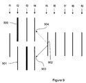
- FIG. 9 when the end of a GOP approaches, in the embodiment described with reference to FIG. 6 , several different bitstreams are generated.
- the images f 2 to f 4 are coded in two forms of bitstream. In the first form, the image f 2 is coded in INTRA 900 whereas it is an image coded in INTER 901 in the second form.
- the image f 3 which is coded in INTRA and in INTER.
- the image f 4 differs slightly in terms of quality in the different bitstreams.
- the image f 5 902 is coded, use is made, as reference for the motion estimation module, of the preceding compressed/decompressed image of one of the two bitstreams, respectively 903 or 904 . If the image of the bitstream 901 is chosen as reference image, the image f 5 is optimized according to the bitstream 901 . If the bitstream transmitted is the bitstream 900 , a slight error, known by the term “drift” may appear starting with the image f 5 , at the time of the decoding and viewing on the client video.
- drift a slight error, known by the term “drift” may appear starting with the image f 5 , at the time of the decoding and viewing on the client video.
- the embodiment illustrated in FIG. 8 is optimal in terms of video compression since a single bitstream is generated.
- this embodiment may not be optimal in terms of synchronization with the peak of the bandwidth. This is because, due to the fact that the buffer memory 804 cannot be empty and that the speeds of flow and filling must be modeled according to the model 811 and the estimated size of the images compressed by the coder 801 , a small error may appear as to the choice of the INTRA image.
- a third embodiment is intended to mitigate the slight drawbacks of the embodiments illustrated in FIGS. 6 and 8 .
- This third embodiment is described in FIG. 10 , which combines aspects of the two first embodiments.
- three bitstreams are generated, at least over some portions of the video, that is to say at least in the vicinity of the end of a GOP.
- a single bitstream is constructed. This common bitstream follows on from a single one of the three bitstreams generated in the vicinity of the end of the GOP (images f 5 to f 9 in FIG. 9 ).
- the probability of the bitstream serving as reference for the common bitstream being chosen is 1 ⁇ 3.
- the embodiment illustrated in FIG. 10 is directed to increasing this probability by applying, to the embodiment illustrated in FIG. 6 , the choice for reference of the common bitstream, of the bitstream generated of which the probability of being chosen is the highest.
- Functions 1003 to 1010 are similar to functions 603 to 610 illustrated in FIG. 6 .
- a video 1000 is transmitted to a coder of MPEG type 1001 which codes it, that is to say compresses it, to form a bitstream 1002 stored in a buffer memory 1004 .
- a coder of MPEG type 1001 which codes it, that is to say compresses it, to form a bitstream 1002 stored in a buffer memory 1004 .
- three different bitstreams are generated. These three bitstreams 1016 , 1017 and 1018 correspond to three different positions of the image coded in INTRA.
- the common bitstream 1019 makes reference to one of the three bitstreams. In this case, at 1015 , the operation of the second embodiment (see FIG.
- bitstream 1018 is chosen as being the one for which the INTRA image coincides best with the peak of the bandwidth, then three bitstreams are generated but when the common part 1019 of the video is compressed, it takes the chosen bitstream 1018 as reference bitstream.
- the algorithm is then the same as that described with reference to FIG. 6 with, at 1012 , the choice being made of the bitstream which carries out the transmission of the INTRA image best synchronized with the peak of the bandwidth. On account of the test 1015 , the probability of choosing the bitstream which does not serve as reference for the common bitstream is low.
- a device implementing the invention is for example a microcomputer 120 connected to different peripherals, for example a digital camera 1107 (or any image acquisition or storage means) connected to a graphics card and supplying information to be processed according to the invention.
- the device 120 could also be a digital camera connected to a network for example a video surveillance camera.
- the device 120 comprises a communication interface 1112 connected to a network 1113 able to transmit digital data to be processed or, conversely, to transmit data processed by the device.
- the device 120 optionally comprises a storage means 1108 such as a hard disk or a drive 1109 for a disk 1110 .
- This disk 1110 may for example be a diskette, a CD-ROM, or a DVD-ROM.
- the storage means 1108 may contain data processed according to the invention as well as each program participating in the implementation of the method of the present invention, which program, once read by the device 120 , is stored by the storage means 1108 .
- the program enabling the device to implement the method of the present invention is stored in read only memory 1102 (termed “ROM”, acronym for “read only memory” in FIG. 11 ).
- the program is received in order to be stored in an identical manner to that described previously, via the communication network 1113 .
- the device 120 is, optionally, connected to a microphone 1111 .
- the data to be processed according to the invention are, in this case, audio signal or include audio signal.
- This same device 120 optionally has a screen 1104 for displaying the data to be processed or serving as an interface with the user, who can thus parameterize certain processing modes, using the keyboard 1114 or any other means (a mouse for example).
- the central processing unit 1100 executes the instructions relative to the implementation of the method of the present invention, which instructions are stored in the read only memory 1102 or by the storage means 1108 .
- the processing programs stored in a non-volatile memory for example the ROM 1102 , are transferred into the random access memory RAM 1103 , which then contains the executable code of the invention, as well as registers for storing the variables necessary for implementing the invention.
- an information storage means which can be read by a computer or microprocessor, integrated or not into the device, and which may possibly be removable, stores a program implementing the method of respectively coding, transmission and decoding.
- the communication bus 1101 enables communication between the different elements included in the microcomputer 120 or connected to it.
- the representation of the bus 1101 is not limiting and, in particular, the central processing unit 1100 is able to communicate instructions to any element of the microcomputer 120 directly or via another element of the microcomputer 120 .
Abstract
-
- a step (805 to 807, 809, 810) of determining times for which the quantity of information that may be sent per unit of time over the network is greater, and respectively less, than its average, on the basis of the substantially cyclical past variation in said quantity of information and
- a step (801 to 805, 812 to 816) of sending over said network, at said times, images corresponding to a greater, and respectively smaller, quantity of information than the average of the images.
Description
-
- a step of determining times for which the quantity of information that may be sent per unit of time over the network is greater than its average, on the basis of the substantially cyclical past variation in said quantity of information and
- a step of sending over said network, at said times, images corresponding to a greater quantity of information than the average of the images.
-
- a step of determining times for which the quantity of information that may be sent per unit of time over the network is less than its average, on the basis of the substantially cyclical past variation in said quantity of information and
- a step of sending over said network, at said times, images corresponding to a smaller quantity of information than the average of the images.
-
- a means for determining times for which the quantity of information that may be sent per unit of time over the network is greater than its average, on the basis of the substantially cyclical past variation in said quantity of information and
- a means for sending over said network, at said times, images corresponding to a greater quantity of information than the average of the images.
-
- a means for determining times for which the quantity of information that may be sent per unit of time over the network is less than its average, on the basis of the substantially cyclical past variation in said quantity of information and
- a means for sending over said network, at said times, images corresponding to a smaller quantity of information than the average of the images.
-
- The TCP protocol may be used, which integrates a congestion control of AIMD type (AIMD being the acronym for “Additive increase Multiplicative Decrease”)
- video transport over RTP may be used (RTP being the acronym for “Real-Time transport protocol”), if a congestion control algorithm is implemented above RTP. In this case, specific information may be added into the RTP messages and specific messages may be sent over RTCP (acronym for “RTP control protocol”) which is the control part of RTP. Different congestion control algorithms may be implemented, for example AIMD or TFRC,
- transport of video over DCCP may be used (DCCP being the acronym for “Datagram Congestion Control Protocol”) which is a protocol making it possible to have several types of congestion control, for example AIMD and TFRC.
T=B*Rtt 2/2*P.
Pr=Bcurr*2*P*t/Bav 2 *Rtt 2
-
- detecting a stationary regime of evolution of the bandwidth,
- predicting peaks of the bandwidth and
- modifying compression times of the images of a video in INTRA mode such that their transmissions correspond to the peaks of the bandwidth.
Claims (12)
Applications Claiming Priority (2)
| Application Number | Priority Date | Filing Date | Title |
|---|---|---|---|
| FR0755941A FR2917919B1 (en) | 2007-06-21 | 2007-06-21 | METHOD AND DEVICE FOR TRANSMITTING IMAGES |
| FR0755941 | 2007-06-21 |
Publications (2)
| Publication Number | Publication Date |
|---|---|
| US20080317117A1 US20080317117A1 (en) | 2008-12-25 |
| US8126049B2 true US8126049B2 (en) | 2012-02-28 |
Family
ID=38988064
Family Applications (1)
| Application Number | Title | Priority Date | Filing Date |
|---|---|---|---|
| US12/137,975 Expired - Fee Related US8126049B2 (en) | 2007-06-21 | 2008-06-12 | Method and a device for transmitting images |
Country Status (2)
| Country | Link |
|---|---|
| US (1) | US8126049B2 (en) |
| FR (1) | FR2917919B1 (en) |
Families Citing this family (2)
| Publication number | Priority date | Publication date | Assignee | Title |
|---|---|---|---|---|
| FR2923118B1 (en) * | 2007-10-30 | 2016-04-01 | Canon Kk | METHOD, DEVICE AND COMPUTER PROGRAM FOR MANAGING THE QUANTITY OF DATA ISSUED BY A TRANSMISSION DEVICE |
| US9568985B2 (en) | 2012-11-23 | 2017-02-14 | Mediatek Inc. | Data processing apparatus with adaptive compression algorithm selection based on visibility of compression artifacts for data communication over camera interface and related data processing method |
Citations (10)
| Publication number | Priority date | Publication date | Assignee | Title |
|---|---|---|---|---|
| WO1999000984A1 (en) | 1997-06-26 | 1999-01-07 | Citrix Systems, Inc. | System for adaptive video/audio transport over a network |
| US20010024470A1 (en) * | 1998-07-06 | 2001-09-27 | U.S. Philips Electronics | Scalable video coding system |
| FR2811098A1 (en) | 2000-07-03 | 2002-01-04 | Canon Res Ct France Sa | Procedure for transfer of electronic documents in a communication network, uses predictions of times when data transfer rates will be maximum to decide when to send data, based on measurement of previous transfers |
| US20020010938A1 (en) * | 2000-05-31 | 2002-01-24 | Qian Zhang | Resource allocation in multi-stream IP network for optimized quality of service |
| US20040190515A1 (en) | 2003-03-24 | 2004-09-30 | International Business Machines Corporation | System and method for providing multiplexing and remultiplexing of MPEG-2 streams |
| US20060053207A1 (en) | 2004-09-08 | 2006-03-09 | Canon Kabushiki Kaisha | Data sharing sequence display method and corresponding sharing device |
| WO2006047324A1 (en) | 2004-10-22 | 2006-05-04 | Hewlett-Packard Development Company, L.P. | Methods and systems that use information about a frame of video data to make a decision about sending the frame |
| US20080225842A1 (en) * | 2007-03-02 | 2008-09-18 | Arnold Goldfein | Method and system for accelerating transmission of data between network devices |
| US7457820B1 (en) | 2003-05-07 | 2008-11-25 | Canon Kabushiki Kaisha | Method of distributing multiresolution digital documents |
| US7961618B1 (en) * | 2006-06-30 | 2011-06-14 | Nextel Communications Inc. | System, method and computer-readable medium for on-demand dynamic bandwidth allocation in a network of antennas for multiple base transceiver stations |
Family Cites Families (1)
| Publication number | Priority date | Publication date | Assignee | Title |
|---|---|---|---|---|
| US6829442B2 (en) * | 2000-12-19 | 2004-12-07 | Lite Cycles, Inc. | High speed optical receiver |
-
2007
- 2007-06-21 FR FR0755941A patent/FR2917919B1/en not_active Expired - Fee Related
-
2008
- 2008-06-12 US US12/137,975 patent/US8126049B2/en not_active Expired - Fee Related
Patent Citations (11)
| Publication number | Priority date | Publication date | Assignee | Title |
|---|---|---|---|---|
| WO1999000984A1 (en) | 1997-06-26 | 1999-01-07 | Citrix Systems, Inc. | System for adaptive video/audio transport over a network |
| US6014694A (en) * | 1997-06-26 | 2000-01-11 | Citrix Systems, Inc. | System for adaptive video/audio transport over a network |
| US20010024470A1 (en) * | 1998-07-06 | 2001-09-27 | U.S. Philips Electronics | Scalable video coding system |
| US20020010938A1 (en) * | 2000-05-31 | 2002-01-24 | Qian Zhang | Resource allocation in multi-stream IP network for optimized quality of service |
| FR2811098A1 (en) | 2000-07-03 | 2002-01-04 | Canon Res Ct France Sa | Procedure for transfer of electronic documents in a communication network, uses predictions of times when data transfer rates will be maximum to decide when to send data, based on measurement of previous transfers |
| US20040190515A1 (en) | 2003-03-24 | 2004-09-30 | International Business Machines Corporation | System and method for providing multiplexing and remultiplexing of MPEG-2 streams |
| US7457820B1 (en) | 2003-05-07 | 2008-11-25 | Canon Kabushiki Kaisha | Method of distributing multiresolution digital documents |
| US20060053207A1 (en) | 2004-09-08 | 2006-03-09 | Canon Kabushiki Kaisha | Data sharing sequence display method and corresponding sharing device |
| WO2006047324A1 (en) | 2004-10-22 | 2006-05-04 | Hewlett-Packard Development Company, L.P. | Methods and systems that use information about a frame of video data to make a decision about sending the frame |
| US7961618B1 (en) * | 2006-06-30 | 2011-06-14 | Nextel Communications Inc. | System, method and computer-readable medium for on-demand dynamic bandwidth allocation in a network of antennas for multiple base transceiver stations |
| US20080225842A1 (en) * | 2007-03-02 | 2008-09-18 | Arnold Goldfein | Method and system for accelerating transmission of data between network devices |
Also Published As
| Publication number | Publication date |
|---|---|
| FR2917919A1 (en) | 2008-12-26 |
| FR2917919B1 (en) | 2010-06-11 |
| US20080317117A1 (en) | 2008-12-25 |
Similar Documents
| Publication | Publication Date | Title |
|---|---|---|
| KR101638223B1 (en) | Method for providing an adaptive streaming service | |
| US8379670B2 (en) | Method and device for transmitting video data | |
| US8462778B2 (en) | Method and device for transmitting data | |
| US10057014B2 (en) | System and method for streaming data | |
| US20130297743A1 (en) | Managed Adaptive Streaming | |
| US20080294789A1 (en) | Method and device for transmitting data | |
| US9781474B2 (en) | Content playback information estimation apparatus and method and program | |
| US20150146778A1 (en) | Controlling Player Buffer and Video Encoder for Adaptive Video Streaming | |
| US20120230390A1 (en) | Adaptive Control of Encoders for Continuous Data Streaming | |
| CN103535047A (en) | Method for streaming video content, node in a network for monitoring video content streaming | |
| US20110013538A1 (en) | Methods and Devices for Estimating a Level of Use of a Communication Network and for Adapting a Level of Subscription to Multicast Sessions | |
| WO2012154152A1 (en) | Apparatus and method for rendering video with retransmission delay | |
| US8311128B2 (en) | Method of processing a coded data stream | |
| KR20130086991A (en) | Estimation method of network jitter for apparatuses transporting coded media data | |
| US9009344B2 (en) | Method of sending data and associated device | |
| US9258347B2 (en) | Encoding of a video frame for transmission to a plurality of clients | |
| US11812114B2 (en) | Method and server for audio and/or video content delivery | |
| US20120236927A1 (en) | Transmission apparatus, transmission method, and recording medium | |
| US8126049B2 (en) | Method and a device for transmitting images | |
| GB2532072A (en) | Feedback management in a multipath communication network | |
| JP2004215201A (en) | Information processing apparatus and information processing method, data communication system, recording medium, and program | |
| Kang et al. | Effective bandwidth based scheduling for streaming media | |
| KR20150086110A (en) | Apparatus and Method for Transmitting Encoded Video Stream | |
| Ceglie et al. | Periodic feedback control for streaming 3D videos in last-generation cellular networks | |
| EP2337257B1 (en) | Method and apparatus of sending encoded multimedia digital data taking into account sending deadlines |
Legal Events
| Date | Code | Title | Description |
|---|---|---|---|
| AS | Assignment |
Owner name: CANON KABUSHIKI KAISHA, JAPAN Free format text: ASSIGNMENT OF ASSIGNORS INTEREST;ASSIGNORS:LE FLOCH, HERVE;NASSOR, ERIC;REEL/FRAME:021238/0356 Effective date: 20080624 |
|
| STCF | Information on status: patent grant |
Free format text: PATENTED CASE |
|
| FPAY | Fee payment |
Year of fee payment: 4 |
|
| FEPP | Fee payment procedure |
Free format text: MAINTENANCE FEE REMINDER MAILED (ORIGINAL EVENT CODE: REM.); ENTITY STATUS OF PATENT OWNER: LARGE ENTITY |
|
| LAPS | Lapse for failure to pay maintenance fees |
Free format text: PATENT EXPIRED FOR FAILURE TO PAY MAINTENANCE FEES (ORIGINAL EVENT CODE: EXP.); ENTITY STATUS OF PATENT OWNER: LARGE ENTITY |
|
| STCH | Information on status: patent discontinuation |
Free format text: PATENT EXPIRED DUE TO NONPAYMENT OF MAINTENANCE FEES UNDER 37 CFR 1.362 |
|
| FP | Lapsed due to failure to pay maintenance fee |
Effective date: 20200228 |