US8123773B1 - Postpartum hemorrhage balloon tamponade catheter - Google Patents
Postpartum hemorrhage balloon tamponade catheter Download PDFInfo
- Publication number
- US8123773B1 US8123773B1 US12/207,578 US20757808A US8123773B1 US 8123773 B1 US8123773 B1 US 8123773B1 US 20757808 A US20757808 A US 20757808A US 8123773 B1 US8123773 B1 US 8123773B1
- Authority
- US
- United States
- Prior art keywords
- balloon
- catheter
- centimeters
- plane
- milliliters
- Prior art date
- Legal status (The legal status is an assumption and is not a legal conclusion. Google has not performed a legal analysis and makes no representation as to the accuracy of the status listed.)
- Active, expires
Links
- 208000018525 Postpartum Hemorrhage Diseases 0.000 title abstract description 5
- 210000004291 uterus Anatomy 0.000 claims abstract description 37
- 230000007704 transition Effects 0.000 claims abstract description 17
- 239000012530 fluid Substances 0.000 claims description 10
- 235000014443 Pyrus communis Nutrition 0.000 claims description 4
- 238000003780 insertion Methods 0.000 abstract description 2
- 230000037431 insertion Effects 0.000 abstract description 2
- 238000000034 method Methods 0.000 description 13
- 239000000463 material Substances 0.000 description 12
- 208000032843 Hemorrhage Diseases 0.000 description 7
- 208000034158 bleeding Diseases 0.000 description 7
- 230000000740 bleeding effect Effects 0.000 description 7
- 230000007246 mechanism Effects 0.000 description 4
- 238000007789 sealing Methods 0.000 description 4
- 238000011282 treatment Methods 0.000 description 4
- FAPWRFPIFSIZLT-UHFFFAOYSA-M Sodium chloride Chemical compound [Na+].[Cl-] FAPWRFPIFSIZLT-UHFFFAOYSA-M 0.000 description 3
- 208000007536 Thrombosis Diseases 0.000 description 3
- 206010046788 Uterine haemorrhage Diseases 0.000 description 3
- 239000008280 blood Substances 0.000 description 3
- 210000004369 blood Anatomy 0.000 description 3
- XNOPRXBHLZRZKH-UHFFFAOYSA-N Oxytocin Natural products N1C(=O)C(N)CSSCC(C(=O)N2C(CCC2)C(=O)NC(CC(C)C)C(=O)NCC(N)=O)NC(=O)C(CC(N)=O)NC(=O)C(CCC(N)=O)NC(=O)C(C(C)CC)NC(=O)C1CC1=CC=C(O)C=C1 XNOPRXBHLZRZKH-UHFFFAOYSA-N 0.000 description 2
- 101800000989 Oxytocin Proteins 0.000 description 2
- 102100031951 Oxytocin-neurophysin 1 Human genes 0.000 description 2
- -1 but not limited to Substances 0.000 description 2
- 210000003679 cervix uteri Anatomy 0.000 description 2
- 230000035606 childbirth Effects 0.000 description 2
- 230000008602 contraction Effects 0.000 description 2
- 230000034994 death Effects 0.000 description 2
- 231100000517 death Toxicity 0.000 description 2
- 230000006870 function Effects 0.000 description 2
- 230000023597 hemostasis Effects 0.000 description 2
- 238000005259 measurement Methods 0.000 description 2
- XNOPRXBHLZRZKH-DSZYJQQASA-N oxytocin Chemical compound C([C@H]1C(=O)N[C@H](C(N[C@@H](CCC(N)=O)C(=O)N[C@@H](CC(N)=O)C(=O)N[C@@H](CSSC[C@H](N)C(=O)N1)C(=O)N1[C@@H](CCC1)C(=O)N[C@@H](CC(C)C)C(=O)NCC(N)=O)=O)[C@@H](C)CC)C1=CC=C(O)C=C1 XNOPRXBHLZRZKH-DSZYJQQASA-N 0.000 description 2
- 229960001723 oxytocin Drugs 0.000 description 2
- 229920002635 polyurethane Polymers 0.000 description 2
- 239000004814 polyurethane Substances 0.000 description 2
- 238000001356 surgical procedure Methods 0.000 description 2
- 206010053567 Coagulopathies Diseases 0.000 description 1
- 244000043261 Hevea brasiliensis Species 0.000 description 1
- 208000034693 Laceration Diseases 0.000 description 1
- 208000000091 Maternal Death Diseases 0.000 description 1
- 239000004677 Nylon Substances 0.000 description 1
- 239000004698 Polyethylene Substances 0.000 description 1
- 206010046796 Uterine inversion Diseases 0.000 description 1
- 206010046798 Uterine leiomyoma Diseases 0.000 description 1
- 206010046910 Vaginal haemorrhage Diseases 0.000 description 1
- 230000001154 acute effect Effects 0.000 description 1
- 238000004026 adhesive bonding Methods 0.000 description 1
- 229940035674 anesthetics Drugs 0.000 description 1
- 210000001367 artery Anatomy 0.000 description 1
- 208000015294 blood coagulation disease Diseases 0.000 description 1
- 230000036772 blood pressure Effects 0.000 description 1
- 230000009852 coagulant defect Effects 0.000 description 1
- 239000013536 elastomeric material Substances 0.000 description 1
- 230000010102 embolization Effects 0.000 description 1
- 239000012634 fragment Substances 0.000 description 1
- 238000002695 general anesthesia Methods 0.000 description 1
- 239000003193 general anesthetic agent Substances 0.000 description 1
- 230000036541 health Effects 0.000 description 1
- 208000031169 hemorrhagic disease Diseases 0.000 description 1
- 230000002439 hemostatic effect Effects 0.000 description 1
- 238000009802 hysterectomy Methods 0.000 description 1
- 230000006872 improvement Effects 0.000 description 1
- 230000002452 interceptive effect Effects 0.000 description 1
- 238000001990 intravenous administration Methods 0.000 description 1
- 230000002262 irrigation Effects 0.000 description 1
- 238000003973 irrigation Methods 0.000 description 1
- 238000002350 laparotomy Methods 0.000 description 1
- 201000010260 leiomyoma Diseases 0.000 description 1
- 238000004519 manufacturing process Methods 0.000 description 1
- 238000012986 modification Methods 0.000 description 1
- 230000004048 modification Effects 0.000 description 1
- 229920003052 natural elastomer Polymers 0.000 description 1
- 229920001194 natural rubber Polymers 0.000 description 1
- 229920001778 nylon Polymers 0.000 description 1
- 230000000414 obstructive effect Effects 0.000 description 1
- 238000012856 packing Methods 0.000 description 1
- 229920000573 polyethylene Polymers 0.000 description 1
- 229920001296 polysiloxane Polymers 0.000 description 1
- 229920000915 polyvinyl chloride Polymers 0.000 description 1
- 239000004800 polyvinyl chloride Substances 0.000 description 1
- 230000008569 process Effects 0.000 description 1
- 230000001020 rhythmical effect Effects 0.000 description 1
- 230000035939 shock Effects 0.000 description 1
- 229910052710 silicon Inorganic materials 0.000 description 1
- 239000010703 silicon Substances 0.000 description 1
- 239000000126 substance Substances 0.000 description 1
- 229920003051 synthetic elastomer Polymers 0.000 description 1
- 239000005061 synthetic rubber Substances 0.000 description 1
- 238000002604 ultrasonography Methods 0.000 description 1
- XLYOFNOQVPJJNP-UHFFFAOYSA-N water Substances O XLYOFNOQVPJJNP-UHFFFAOYSA-N 0.000 description 1
Images


Classifications
-
- A—HUMAN NECESSITIES
- A61—MEDICAL OR VETERINARY SCIENCE; HYGIENE
- A61M—DEVICES FOR INTRODUCING MEDIA INTO, OR ONTO, THE BODY; DEVICES FOR TRANSDUCING BODY MEDIA OR FOR TAKING MEDIA FROM THE BODY; DEVICES FOR PRODUCING OR ENDING SLEEP OR STUPOR
- A61M25/00—Catheters; Hollow probes
- A61M25/10—Balloon catheters
- A61M25/1002—Balloon catheters characterised by balloon shape
-
- A—HUMAN NECESSITIES
- A61—MEDICAL OR VETERINARY SCIENCE; HYGIENE
- A61M—DEVICES FOR INTRODUCING MEDIA INTO, OR ONTO, THE BODY; DEVICES FOR TRANSDUCING BODY MEDIA OR FOR TAKING MEDIA FROM THE BODY; DEVICES FOR PRODUCING OR ENDING SLEEP OR STUPOR
- A61M25/00—Catheters; Hollow probes
- A61M25/10—Balloon catheters
- A61M2025/1043—Balloon catheters with special features or adapted for special applications
- A61M2025/1065—Balloon catheters with special features or adapted for special applications having a balloon which is inversely attached to the shaft at the distal or proximal end
-
- A—HUMAN NECESSITIES
- A61—MEDICAL OR VETERINARY SCIENCE; HYGIENE
- A61M—DEVICES FOR INTRODUCING MEDIA INTO, OR ONTO, THE BODY; DEVICES FOR TRANSDUCING BODY MEDIA OR FOR TAKING MEDIA FROM THE BODY; DEVICES FOR PRODUCING OR ENDING SLEEP OR STUPOR
- A61M2210/00—Anatomical parts of the body
- A61M2210/14—Female reproductive, genital organs
- A61M2210/1433—Uterus
Definitions
- This disclosure relates to apparatus and methods for controlling postpartum hemorrhaging. More particularly, this disclosure discusses a pear-shaped balloon tamponade catheter for controlling uterine postpartum hemorrhaging.
- PPH Postpartum hemorrhage
- the basic causes of PPH are failure of the uterus to contract and retract (80-90%) as a result of obstructive blood clots, fibroids, tissue fragments, or other anomalies; uterine lacerations; uterine inversions; coagulation disorders; and other similar complications associated with childbirth.
- PPH can be treated in a variety of manners.
- a uterine fundal massage can help to expel blood clots and encourage natural contraction and retraction of the uterine musculature.
- the administration of oxytocin can produce rapid, strong, and rhythmic contractions that aid hemostasis.
- fundal massages and the administration of oxytocin are not effective at controlling PPH. In such cases, more invasive treatments may be required. For instance, the treatment of acute PPH may require a hysterectomy, major vessel embolization, and/or artery ligation (laparotomy).
- a tamponade is used to control PPH or to buy time until a more invasive surgery can be performed.
- tamponade intervention has involved packing the uterus tight with several yards of gauze under general anesthesia. More recently, however, tamponade intervention has involved the use of a Foley catheter with a large bulb or multiple Foley catheters that are to be inflated within the uterus.
- the balloon tamponade catheter includes a catheter body with an expandable balloon located distally on the catheter body for insertion into the uterus.
- the balloon has a substantially pear-shaped appearance when it is uninflated and/or inflated.
- the balloon can achieve such an appearance in any suitable manner, in some cases, the balloon comprises a first hemisphere and a second smaller hemisphere.
- the first hemisphere has a first plane of maximum diameter that is larger than the second hemisphere's second plane of maximum diameter.
- the first hemisphere is distally located on the catheter body with respect to the second hemisphere.
- the balloon comprises a transition section that spans between the first plane of maximum diameter and the second plane of maximum diameter. While the transition section can have any suitable shape, in some circumstances, as the transition section extends between a perimeter of the first plane and a perimeter of a second plane, at least a portion of the section bows in towards the catheter body. In one example, the transition section bows in towards the catheter when the interior pressure of the balloon is substantially equal to the pressure exerted on the exterior of the balloon. In another example, the transition section bows in towards the catheter when the balloon is inflated at or below a maximum volume.
- the catheter body may comprise virtually any catheter body type that can be used to inflate, deflate, and/or insert the balloon into the uterus.
- the catheter comprises a dual-lumen catheter with a first lumen and a second lumen.
- the first lumen has an opening at the distal end of the catheter body. Accordingly, fluids or other materials may be passed through the first lumen to irrigate and/or to drain the uterus.
- the second lumen may comprise an aperture between the interior of the second lumen and the interior of the balloon.
- the second lumen is configured to allow the balloon to be inflated or deflated.
- the distal end of the catheter may extend to any desired location with respect to a distal end of the balloon's first hemisphere, the distal end may stop at or proximal to the distal end of the first hemisphere. In this manner, the distal end of the first hemisphere can contact the uterus without interference from the distal end of the catheter body.
- the described balloon tamponade catheter may be able to contact and apply pressure to most if not all of the interior surfaces of the uterus. In this manner, the balloon tamponade catheter may effectively stop or control bleeding in patients with PPH.
- the apparatus and methods of the present invention may be particularly useful in the area of controlling PPH, those skilled in the art can appreciate that the apparatus and methods can be used in a variety of different applications, including in controlling vaginal bleeding.
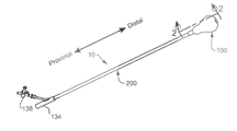
- FIG. 1 illustrates some embodiments of a balloon tamponade catheter
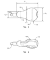
- FIG. 2 illustrates a cross-sectional view through the balloon tamponade catheter of FIG. 1 along line 2 - 2 ;
- FIG. 3 illustrates a view of some embodiments of an uninflated pear-shaped balloon tamponade
- FIG. 4 illustrates a view of some embodiments a collapsed pear-shaped balloon tamponade
- FIG. 5 illustrates view of some embodiments of an inflated pear-shaped balloon tamponade.
- the present invention is drawn to a postpartum hemorrhage balloon tamponade catheter (“BT Catheter”).
- the BT Catheter is adapted so that a balloon located at a distal end of the catheter can be inserted into a uterus where the balloon can be inflated to apply pressure to an interior surface of the uterus. In this manner, the BT Catheter can reduce uterine bleeding and control PPH.
- the BT Catheter may comprise any component that allows it to fulfill this or other similar functions
- FIG. 1 shows a representative embodiment in which the BT Catheter 10 comprises an expandable balloon 100 and a catheter body 200 . To provide a better understanding of the BT Catheter, the balloon and the catheter body are described below in more detail.
- the balloon may have any characteristic or component that allows it to be inserted into a uterus where it can be inflated to apply pressure to one or more internal uterine surfaces so as to reduce uterine bleeding or otherwise treat PPH.
- the balloon has a pear-shaped appearance.
- the term pear-shaped may refer to a shape that bulges towards a distal end and tapers near a proximal end.
- FIG. 2 shows a representative embodiment in which the pear-shaped balloon 100 is broad near its distal end 102 and tapered near its proximal end 104 . Additionally, FIG. 2 shows that in some circumstances, the balloon 100 comprises two tiers. In particular, FIG.
- the balloon 100 comprises a first hemisphere 106 and a smaller second hemisphere 108 .
- the first hemisphere 106 comprises a substantially rounded portion that extends from the balloon's distal end 102 towards a first plane of maximum diameter 110 .
- the second hemisphere 108 comprises a smaller, substantially rounded portion that extends from the balloon's proximal end 104 towards a second plane of maximum diameter 112 .
- the first and second hemisphere can have any characteristic that allows the balloon to have a substantially pear-shaped appearance.
- FIG. 2 shows the first plane of maximum diameter 110 is a portion of widest diameter for the rest of the first hemisphere 106 .
- FIG. 2 shows the second plane of maximum diameter 112 is a widest diameter of the second hemisphere 108 .
- the second plane 112 is located at a position in the balloon 100 in which the second hemisphere begins to transition from its substantially semi-spherical shape and to flare out towards the first hemisphere.
- the first and second planes of maximum diameter can be located in any position that allows the balloon to have a substantially pear-shaped appearance.
- FIG. 3 shows a non-limiting embodiment where the first plane of maximum diameter 110 is located distally with respect to a longitudinal midpoint 114 of the balloon 100 .
- FIG. 3 further shows a non-limiting embodiment in which the second plane of maximum diameter 112 is located proximally on the catheter body with respect to the balloon's longitudinal midpoint 114 .
- the balloon is expandable, to some extent, its shape depends on its internal pressure. Accordingly, the interior 116 of the balloon 100 (shown in FIG. 2 ) can have any suitable pressure that allows the balloon to be inserted into a uterus, apply pressure to one or more internal uterine surfaces, and/or to be withdrawn from the uterus.
- the balloon has an internal pressure that allows the balloon to be partially or completely “collapsed” by external pressures.
- FIG. 4 shows that, in some embodiments, when the balloon's internal pressure is lower than the atmospheric pressure that is exerted on the balloon's exterior surface 118 , the balloon 100 is partially collapsed around the catheter body 200 .
- the balloon is not inflated, per se, it has an internal pressure that is sufficient to prevent it from collapsing under atmospheric pressure.
- the balloon is “uninflated” when, as shown in FIG. 3 , the balloon's internal pressure is substantially equal to the atmospheric pressure exerted on the balloon's exterior 118 .
- FIG. 5 shows some embodiments in which the balloon 100 is “inflated”, or in which the balloon's interior pressure is greater than the atmospheric pressure exerted on the balloon's exterior surface 118 .
- the interior of the balloon may have any volume that allows the balloon to have a substantially pear-shaped appearance.
- the uninflated balloon has an internal volume from about 40 to about 120 milliliters.
- the uninflated balloon has an internal volume that is from about 60 to about 100 milliliters.
- the uninflated balloon comprises an internal volume that is from about 70 to about 90 milliliters.
- the uninflated balloon has an internal volume of about 80 milliliters ⁇ 5 milliliters.
- the balloon When the balloon is inflated, it may have virtually any maximum internal volume that allows the balloon to apply pressure to internal uterine surfaces and reduce bleeding.
- the balloon can be inflated to comprise a maximum volume from about 50 to about 1,000 milliliters.
- the inflated balloon has a maximum internal volume of from about 100 to about 550 milliliters (e.g., about 500 milliliters).
- the balloon has a maximum internal volume from about 150 to about 350 milliliters.
- the inflated balloon has a maximum internal volume of from about 200 to about 300 milliliters.
- the balloon may be inflated to a maximum volume of about 250 milliliters ⁇ 25 milliliters).
- the first and second planes of maximum diameter can have any diameter that allows the balloon to have a pear-shaped appearance.
- the uninflated balloon comprises a first plane of maximum diameter having a diameter X 1 (illustrated in FIG. 3 ) that is from about 2 to about 7 centimeters.
- the first plane of maximum diameter in the uninflated balloon has a diameter that is from about 4.1 to about 5.1 centimeters.
- the first plane has a diameter that is from about 4.3 to about 4.9 centimeters.
- the first plane in the uninflated balloon has a diameter that is from about 4.5 to about 4.7 centimeters.
- the first plane in some typical embodiments of the uninflated balloon is about 4.6 centimeters ⁇ 0.05 centimeters.
- the second plane has a diameter X 2 (illustrated in FIG. 3 ) that is from about 0.8 to about 3.8 centimeters.
- the uninflated balloon comprises a second plane having a diameter that is from about 1.8 to about 2.8 centimeters.
- the second plane of the uninflated balloon has a diameter that is from about 2 to about 2.6 centimeters.
- the second plane in the uninflated balloon has a diameter from about 2.2 to about 2.4 centimeters.
- the second plane of the uninflated balloon may have a diameter of about 2.3 centimeters ⁇ 0.05 centimeters.
- the diameter of the first plane can be larger than the diameter of the second plane by any suitable ratio that gives the balloon a pear-shaped appearance and allows the balloon to act as intended.
- the first plane in the uninflated balloon has a diameter that is from about 1.2 to about 2.8 times larger than the second plane's diameter.
- the first plane's diameter in the uninflated balloon is from about 1.5 to about 2.5 times larger than the diameter of the second plane.
- the first plane in the uninflated balloon is from about 1.7 to about 2.3 times larger than the second plane's diameter.
- the diameter of the first plane in the uninflated balloon may be about 2 ( ⁇ 0.2) times larger than the diameter of the second plane.
- the first and second planes of maximum diameter may have any diameter that allows the balloon to have a pear-shaped appearance.
- the first plane comprises a diameter having a length selected from about 6.3 to about 11.5 centimeters; about 7.6 to about 10.2 centimeters; and about 8 to about 9 centimeters.
- the second plane has a diameter with a length selected from about 3.8 to about 10.9 centimeters; about 6.4 to about 9.6 centimeters; and about 7 to about 8 centimeters.
- the diameter of the first plane can be larger than the diameter of the second plane by any suitable ratio that allows the balloon to have a pear-shaped appearance and perform its intended functions. Indeed, in some embodiments, in the inflated balloon, the diameter of the first plane is larger than the diameter of the second plane by a ratio that is selected from between about 1.1 and about 3, between about 1.1 and about 1.6, and between about 1.1 and about 1.2.
- the balloon comprises a transition section 122 that extends between the first and second planes of maximum diameter.
- the transition section can have any suitable shape that allows the balloon to have a pear-shaped appearance and to apply enough pressure to an internal uterine surface to treat PPH.
- FIG. 2 illustrates a taper line 120 that extends from a perimeter of the first plane 110 to a corresponding perimeter of the second plane 112 .
- FIG. 2 further illustrates one example in which at least a portion of the transition section 122 bows inward from the taper line 120 , towards the catheter body 200 .
- At least a portion of the transition section substantially follows the taper line so as to extend in a substantially straight line from a perimeter of the first plane to a perimeter of the second plane. In still another example that is not illustrated, at least a portion of the transition section can cross the taper line so as to bow away from the catheter body.
- the balloon can have any suitable length that allows the BT Catheter to fulfill its intended purposes.
- the length Y (shown in FIG. 3 ) between the distal end 102 and the proximal end 104 of the uninflated balloon 100 is from about 5 to about 13 centimeters.
- the length between the distal and proximal end of the balloon is from about 6 to about 10 centimeters.
- the length between the distal and proximal end of the balloon is from about 6.4 to about 9 centimeters.
- the length of the balloon may vary little, if any, when the balloon is inflated and/or collapsed.
- the BT Catheter can comprise any catheter body that allows the balloon to be located at a distal end of the catheter body and to be inserted into a uterus.
- suitable catheters comprise a single-lumen and a dual-lumen catheter.
- FIGS. 1 and 2 show one presently preferred embodiment in which the catheter body 200 is a dual-lumen catheter comprising a first lumen 124 and a second lumen 126 .
- the first lumen may comprise any component or characteristic suitable for use with the BT Catheter
- the first lumen comprises at least one opening that is disposed at or near the distal end 128 of the catheter body 200 .
- the first lumen 124 comprises an opening 130 at the catheter body's distal end 128 .
- the distal end 102 of the balloon 100 defines an aperture 132 that corresponds with the opening 130 of the first lumen 124 .
- fluids or other materials may pass through the first lumen.
- fluids such as a sterile saline solution or another physiologic solution
- fluids and/or other materials such as blood, blood clots, irrigation fluid, and so forth, may be drained from the uterus through the first lumen. This drainage may allow the catheter to better contact internal uterine surfaces to reduce or prevent bleeding and bleeding diathesis.
- FIG. 1 shows some embodiments where the first lumen (not shown) of the catheter body 200 comprises a connecting mechanism 134 .
- the first lumen can comprise any connecting suitable for use with the BT Catheter, including a flared frictional fitting, a Luer lock fitting, and the like.
- the connecting mechanism can connect the first lumen with any suitable apparatus, such as vessel to collect and/or measure fluids and materials that drain from the uterus, a vessel that can be used to irrigate the uterus, etc.
- the second lumen, or inflation lumen may comprise any component or characteristic that allows a distending medium (e.g., a sterile saline solution, water, etc.) to pass through the second lumen so as to inflate and/or deflate the balloon without unduly interfering with the operation of the BT Catheter.
- a distending medium e.g., a sterile saline solution, water, etc.
- FIG. 2 shows some embodiments in which the second lumen 126 comprises at least one hole 136 that extends between the second lumen 126 and the interior 116 of the balloon 100 .
- the second lumen may comprise an inflation control valve.
- a valve can serve many purposes, including maintaining the balloon in an inflated state and controllably deflating the balloon when it is desired that the pressure supplied to the uterine cavity be reduced or altogether removed.
- the inflation control valve may comprise any suitable valve, including a ball valve, a needle valve, a flapper-style valve, a one-way valve, a two-way valve, an inline rotary valve, an auto-pressure sensing mechanism that prevents the balloon from being over inflated or will bleed off pressure as the uterus contracts, etc.
- FIG. 1 shows some embodiments in which the control valve comprises an inline rotary valve 138 .
- the second lumen may comprise connecting portion that is adapted to connect the second lumen to an apparatus that can inflate and or deflate the balloon.
- the second lumen may comprise flared friction fitting, a Luer lock fitting, and so forth.
- apparatus that can be attached to the connecting portion may include a syringe, a pump, an intravenous (“IV”) bag, or another item that can be attached to the second lumen to inflate and/or deflate the balloon.
- the distal end of the catheter body may be located in any suitable location with respect to the distal end of the first hemisphere.
- the distal end of the catheter body may stop short of or be substantially even with the distal end of the first hemisphere.
- FIG. 2 shows some embodiments in which the distal end 128 of the catheter body is disposed substantially even with, and does not extend distally past, the balloon's distal end 102 .
- the first hemisphere may be able to contact one or more internal uterine surfaces without the distal end of the catheter body coming between the distal end of the first hemisphere and the uterine surface(s). Accordingly, in such embodiments, the BT Catheter may further reduce bleeding and improve treatment of PPH.
- the BT Catheter can optionally comprise any other suitable component or characteristic that allows it to fulfill its intended purposes.
- the balloon is coated or impregnated with a hemostatic material, which may help control bleeding when the balloon contacts internal uterine surfaces.
- the BT Catheter comprises a rigid delivery sheath through which at least a portion of the catheter extends.
- the catheter body comprises a substantially rigid portion that may allow the catheter body to maintain its shape so the balloon can be easily guided into the uterus.
- the balloon may have any suitable thickness or Shore durometer measurement.
- the balloon may have a thickness selected from about 0.38 millimeters to about 0.89 millimeters and about 0.43 to about 0.69 millimeters.
- the balloon material may have a Shore durometer measurement selected from about 15 to about 4 and about 20 to about 35 on the A scale.
- the components of the BT Catheter may be fabricated of a variety of materials suitable for medical and health care applications.
- the balloon may be fabricated from an expandable material, including, but not limited to, polyurethane, silicone, or another medical-grade elastomeric material.
- the catheter body may comprise medical-grade nylon, polyurethane, polyethylene, polyvinyl chloride, silicon, natural rubber, synthetic rubber, or other suitable material.
- the BT Catheter can be made using any known or novel fabrication technique.
- the balloon can be molded or extruded as known in the art.
- the balloon can be attached to the catheter body in any suitable manner.
- the balloon can be attached to the catheter body by adhesive bonding, heat sealing, chemical sealing, mechanical sealing, combinations thereof, or any other suitable sealing mechanism.
- FIG. 2 shows some embodiments in which the distal end 102 of the balloon 100 is attached to the catheter body 200 with an adhesively bonded internal seal 140 .
- FIG. 2 shows some embodiments where the proximal end 104 of the balloon 100 is attached to the catheter body 200 with an adhesively bonded external seal 142 .
- the BT Catheter can be used in any suitable manner that allows it to apply pressure to one or more internal uterine surfaces and, thereby, to treat PPH. Indeed, methods for using tamponade catheters are well known in the art. Nevertheless, in order to better explain the BT Catheter, a non-limiting example of the BT Catheter's use is given herein.
- the BT Catheter is inserted transvaginally through the cervix and into the uterus.
- the pear-shaped balloon is progressively inflated to apply pressure to one or more internal uterine surfaces.
- the balloon is inflated so as to substantially fill the uterus.
- the approximate uterine volume can be determined by ultrasound or direct examination, and the balloon can be inflated so as to have a similar volume. In other cases, however, the balloon is simply inflated until fluid drainage from the uterus stops.
- a fluid collection bag may be attached to the first lumen so that hemostasis can be monitored. However, if there is no drainage through the first lumen and/or the fundus increases in height, the first lumen may be flushed with a solution (e.g., a sterile saline solution).
- a solution e.g., a sterile saline solution
- the inflated balloon can be left in the patient and monitored for any suitable period of time (e.g., less than 24 hours). Once the BT Catheter is to be removed from the uterus, the pear-shaped balloon is slowly deflated. Once deflated to the collapsed or uninflated state, the balloon and catheter body can be retracted from the uterus and vaginal canal.
- the BT Catheter can have several noteworthy characteristics.
- the pear shape of the balloon may allow the balloon to contact a larger portion of the interior uterine surfaces than some conventional apparatus used that are used to control PPH.
- the balloon's pear shape may allow the balloon to apply a more even pressure across the internal surfaces of the uterus.
- the balloon's pear shape may allow the balloon to apply substantially the same pressure (e.g., N/m 2 , dynes/cm 2 , p.s.i., etc.) to the uterus near the cervix as it does at the opposite end of the uterus.
- the BT catheter may control bleeding and PPH better than some conventional apparatus.
- the use of BT Catheter may be less invasive than some methods and may not require the use of anesthetics.
Abstract
Description
Claims (15)
Priority Applications (1)
| Application Number | Priority Date | Filing Date | Title |
|---|---|---|---|
| US12/207,578 US8123773B1 (en) | 2008-09-10 | 2008-09-10 | Postpartum hemorrhage balloon tamponade catheter |
Applications Claiming Priority (1)
| Application Number | Priority Date | Filing Date | Title |
|---|---|---|---|
| US12/207,578 US8123773B1 (en) | 2008-09-10 | 2008-09-10 | Postpartum hemorrhage balloon tamponade catheter |
Publications (1)
| Publication Number | Publication Date |
|---|---|
| US8123773B1 true US8123773B1 (en) | 2012-02-28 |
Family
ID=45694429
Family Applications (1)
| Application Number | Title | Priority Date | Filing Date |
|---|---|---|---|
| US12/207,578 Active 2030-03-17 US8123773B1 (en) | 2008-09-10 | 2008-09-10 | Postpartum hemorrhage balloon tamponade catheter |
Country Status (1)
| Country | Link |
|---|---|
| US (1) | US8123773B1 (en) |
Cited By (8)
| Publication number | Priority date | Publication date | Assignee | Title |
|---|---|---|---|---|
| US9364638B2 (en) | 2014-01-21 | 2016-06-14 | Cook Medical Technologies Llc | Adjustable vaginal anchor for uterine tamponade device and methods of using the same |
| US9421036B2 (en) | 2012-04-08 | 2016-08-23 | Jhpiego Corporation | Automatically-deflating, postpartum tamponade |
| US20170150970A1 (en) * | 2015-11-30 | 2017-06-01 | Universitätsklinikum Halle (Saale) | Device for use in performing organ occlusions, especially an intrauterine tracheal occlusion in the treatment of a congenital fetal diaphragmatic hernia |
| US10105070B2 (en) | 2014-11-17 | 2018-10-23 | 3VO Medical, Inc. | Intrauterine access catheter for delivering and facilitating operation of a medical apparatus for assisting parturition |
| US20190069929A1 (en) * | 2017-09-01 | 2019-03-07 | Cook Medical Technologies Llc | Postpartum hemorrhage balloon system |
| US11141194B2 (en) * | 2018-06-26 | 2021-10-12 | Atom Medical Corporation | Uterine hemostatic balloon unit |
| IT202000009013A1 (en) * | 2020-04-27 | 2021-10-27 | Milano Politecnico | DEVICE FOR THE TREATMENT OF POST-PARTUM UTERINE Bleeding |
| US11717325B2 (en) | 2017-12-03 | 2023-08-08 | Nasser Kamal Abd Elaal | Medicated uterine balloon with cervical barricade for management of postpartum hemorrhage |
Citations (15)
| Publication number | Priority date | Publication date | Assignee | Title |
|---|---|---|---|---|
| US3152592A (en) | 1961-09-13 | 1964-10-13 | Frederic E B Foley | Self-inflating bag catheter |
| US4018230A (en) * | 1974-04-04 | 1977-04-19 | Kazuo Ochiai | Cervical dilator |
| US4137922A (en) * | 1973-03-07 | 1979-02-06 | Ortho Pharmaceutical Corp. | Dilator for cervical canal |
| US5419763A (en) * | 1994-01-04 | 1995-05-30 | Cortrak Medical, Inc. | Prostatic drug-delivery catheter |
| US5947991A (en) * | 1997-01-07 | 1999-09-07 | Cowan; Robert K. | Single balloon device for cervix |
| US6024753A (en) * | 1996-02-05 | 2000-02-15 | Atos Medical Ab | Device for staunching uterus bleeding |
| US20010007945A1 (en) | 1999-12-06 | 2001-07-12 | Hadi Piraka | Uterine balloon apparatus and method |
| US20030060800A1 (en) * | 2001-09-24 | 2003-03-27 | Ethicon, Inc. | Device and method for aligning with the tubal ostium |
| US6648842B2 (en) * | 1997-04-15 | 2003-11-18 | Wilhelm Horkel | Delivery preparation and facilitation device and preparatory gymnastics |
| US6676680B1 (en) | 2001-07-17 | 2004-01-13 | Polyzen, Inc. | Tamponade device to control post-partum hemorrhage |
| US20040030352A1 (en) * | 2000-09-20 | 2004-02-12 | Mcgloughlin Timothy Mary | Device for staunching vagina bleeding |
| US20040267378A1 (en) * | 2003-06-24 | 2004-12-30 | Gazi Bashir Mussa | Semi-stationary balloon in the gastric antrum provided with connecting an anchoring rod for inducing weight reduction in human beings |
| US20060235461A1 (en) * | 2005-04-14 | 2006-10-19 | Harter Steven B | Single balloon ripening device with novel inserter and inflator |
| US7220252B2 (en) | 2003-07-18 | 2007-05-22 | Polyzen, Inc. | Inflatable dual balloon catheter |
| US20080027421A1 (en) | 2006-07-27 | 2008-01-31 | Vancelette David W | CryoBalloon Treatment for Postpartum Hemorrhage |
-
2008
- 2008-09-10 US US12/207,578 patent/US8123773B1/en active Active
Patent Citations (19)
| Publication number | Priority date | Publication date | Assignee | Title |
|---|---|---|---|---|
| US3152592A (en) | 1961-09-13 | 1964-10-13 | Frederic E B Foley | Self-inflating bag catheter |
| US4137922A (en) * | 1973-03-07 | 1979-02-06 | Ortho Pharmaceutical Corp. | Dilator for cervical canal |
| US4018230A (en) * | 1974-04-04 | 1977-04-19 | Kazuo Ochiai | Cervical dilator |
| US5419763A (en) * | 1994-01-04 | 1995-05-30 | Cortrak Medical, Inc. | Prostatic drug-delivery catheter |
| US5419763B1 (en) * | 1994-01-04 | 1997-07-15 | Cor Trak Medical Inc | Prostatic drug-delivery catheter |
| US6024753A (en) * | 1996-02-05 | 2000-02-15 | Atos Medical Ab | Device for staunching uterus bleeding |
| US5947991A (en) * | 1997-01-07 | 1999-09-07 | Cowan; Robert K. | Single balloon device for cervix |
| US6648842B2 (en) * | 1997-04-15 | 2003-11-18 | Wilhelm Horkel | Delivery preparation and facilitation device and preparatory gymnastics |
| US6520977B2 (en) | 1999-12-06 | 2003-02-18 | Hadi Piraka | Uterine balloon apparatus and method |
| US20010007945A1 (en) | 1999-12-06 | 2001-07-12 | Hadi Piraka | Uterine balloon apparatus and method |
| US20040030352A1 (en) * | 2000-09-20 | 2004-02-12 | Mcgloughlin Timothy Mary | Device for staunching vagina bleeding |
| US6676680B1 (en) | 2001-07-17 | 2004-01-13 | Polyzen, Inc. | Tamponade device to control post-partum hemorrhage |
| US20030060800A1 (en) * | 2001-09-24 | 2003-03-27 | Ethicon, Inc. | Device and method for aligning with the tubal ostium |
| US6758831B2 (en) * | 2001-09-24 | 2004-07-06 | Ethicon, Inc. | Device and method for aligning with the tubal ostium |
| US20040267378A1 (en) * | 2003-06-24 | 2004-12-30 | Gazi Bashir Mussa | Semi-stationary balloon in the gastric antrum provided with connecting an anchoring rod for inducing weight reduction in human beings |
| US7220252B2 (en) | 2003-07-18 | 2007-05-22 | Polyzen, Inc. | Inflatable dual balloon catheter |
| US20070239110A1 (en) | 2003-07-18 | 2007-10-11 | Shah Tilak M | Treatment methods utilizing inflatable dual balloon catheter |
| US20060235461A1 (en) * | 2005-04-14 | 2006-10-19 | Harter Steven B | Single balloon ripening device with novel inserter and inflator |
| US20080027421A1 (en) | 2006-07-27 | 2008-01-31 | Vancelette David W | CryoBalloon Treatment for Postpartum Hemorrhage |
Non-Patent Citations (8)
| Title |
|---|
| Bakri, YN et al., "Tamponade-Balloon for Obstetrical Bleeding," International Journal of Gynecology and Obstetrics, vol. 74(2), Aug. 2001, pp. 139 to 142. |
| Bowen, LW et al., "Use of a Large Foley Catheter Balloon to Control Postpartum Hemorrhage Resulting from a Low Placental Implantation, A Report of Two Cases," The Journal of Reproductive Medicine, Aug. 1985. |
| DeLoor, Jeanette A. et al., "Foley Catheters for Uncontrollable Obstetric or Gynelogical Hemorrhage," The American College of Obstetricians Gynecologists, Jan. 1996. |
| Goldrath, MH, "Uterine Tamponade for the Control of Acute Uterine Bleeding," American Journal Obstetrics Gynecology, Dec. 15, 1938, vol. 147(8), pp. 869 to 872. |
| Kauff, Noah D., "Intractable Bleeding Managed with Foley Catheter Tamponade after Dilation and Evacuation," American Journal Obstetrics Gynecology, Oct. 1994, pp. 957 to 958. |
| Marcovici, Iacob et al., "Postpartum Hemorrhage and Intrauterine Balloon Tamponade, A Report of Three Cases," The Journal of Reproductive Medicine, vol. 2, No. 2, Feb. 1999, pp. 122 to 126. |
| Marcovici, Iacob et al., "Postpartum Hemorrhage-A Review," Jurnalul de Chirurgie, Iasi, 2005, vol. 1, Nr. 4, Aug. 27, 2005, pp. 383 to 389. |
| Mousa, HA et al., "Major Postpartum Hemorrhage," Current Opinions of Obstetrics and Gynecology, vol. 13(6), Dec. 2001, pp. 595 to 603. |
Cited By (14)
| Publication number | Priority date | Publication date | Assignee | Title |
|---|---|---|---|---|
| US9421036B2 (en) | 2012-04-08 | 2016-08-23 | Jhpiego Corporation | Automatically-deflating, postpartum tamponade |
| US9364638B2 (en) | 2014-01-21 | 2016-06-14 | Cook Medical Technologies Llc | Adjustable vaginal anchor for uterine tamponade device and methods of using the same |
| US10925501B2 (en) | 2014-11-17 | 2021-02-23 | 3VO Medical, Inc. | Intrauterine access catheter for delivering and facilitating operation of a medical apparatus for assisting parturition |
| US10105070B2 (en) | 2014-11-17 | 2018-10-23 | 3VO Medical, Inc. | Intrauterine access catheter for delivering and facilitating operation of a medical apparatus for assisting parturition |
| US10206595B2 (en) | 2014-11-17 | 2019-02-19 | 3VO Medical, Inc. | Intrauterine balloon apparatus, system, and method for augmenting uterine birthing forces during parturition |
| US11877850B2 (en) | 2014-11-17 | 2024-01-23 | 3VO Medical, Inc. | Intrauterine access catheter for delivering and facilitating operation of a medical apparatus for assisting parturition |
| US10856754B2 (en) | 2014-11-17 | 2020-12-08 | 3VO Medical, Inc. | Intrauterine balloon apparatus, system, and method for augmenting uterine birthing forces during parturition |
| US20170150970A1 (en) * | 2015-11-30 | 2017-06-01 | Universitätsklinikum Halle (Saale) | Device for use in performing organ occlusions, especially an intrauterine tracheal occlusion in the treatment of a congenital fetal diaphragmatic hernia |
| US10813668B2 (en) * | 2017-09-01 | 2020-10-27 | Cook Medical Technologies Llc | Postpartum hemorrhage balloon system |
| US20190069929A1 (en) * | 2017-09-01 | 2019-03-07 | Cook Medical Technologies Llc | Postpartum hemorrhage balloon system |
| US11717325B2 (en) | 2017-12-03 | 2023-08-08 | Nasser Kamal Abd Elaal | Medicated uterine balloon with cervical barricade for management of postpartum hemorrhage |
| US11141194B2 (en) * | 2018-06-26 | 2021-10-12 | Atom Medical Corporation | Uterine hemostatic balloon unit |
| IT202000009013A1 (en) * | 2020-04-27 | 2021-10-27 | Milano Politecnico | DEVICE FOR THE TREATMENT OF POST-PARTUM UTERINE Bleeding |
| WO2021220151A1 (en) * | 2020-04-27 | 2021-11-04 | Politecnico Di Milano | Uterine device for treating postpartum hemorrhage |
Similar Documents
| Publication | Publication Date | Title |
|---|---|---|
| US8123773B1 (en) | Postpartum hemorrhage balloon tamponade catheter | |
| US9888927B2 (en) | Balloon tamponade | |
| AU742942B2 (en) | Back-up retention member drainage catheter | |
| US9427239B2 (en) | Apparatus and method of use for an adjustable radial and ulnar compression wristband | |
| US7220252B2 (en) | Inflatable dual balloon catheter | |
| US3516407A (en) | Inflatable intranasal tampon | |
| US20080319472A1 (en) | Cervical dilator catheter | |
| JP3804351B2 (en) | Balloon catheter | |
| US10813648B2 (en) | Systems and methods for effecting the total and partial occlusion of the aorta of a living being | |
| AU2018237167A1 (en) | Combined stent reperfusion system | |
| CN103111010A (en) | Double-cavity sacculus tube and application thereof | |
| CN112739405A (en) | Introducer for uterine tamponade assembly with echogenic elements | |
| CN209186808U (en) | A kind of laparoscope hemostasis device | |
| CN215914766U (en) | Multipurpose anal canal | |
| CN205287205U (en) | Double cannula formula fistulization pipe | |
| CN107198604B (en) | Ileum fistulization pipe | |
| CN212547921U (en) | Aorta blocking perfusion device | |
| US20230089826A1 (en) | Trans-anal inflow catheter for intermittently triggering a reflex-coordinated defecation | |
| CN109453441A (en) | A kind of palm shape drug application drainage from indwelling bag | |
| CN209347889U (en) | Cardiovascular dilating sacculus | |
| EP4017381A1 (en) | Gastroesophageal aortic occlusion device and method | |
| JP2023537822A (en) | Devices and methods for vascular occlusion | |
| CN115721376A (en) | Plugging balloon catheter with suction function at far end | |
| CN111166409A (en) | Hemostatic balloon for obstetrics and gynecology department |
Legal Events
| Date | Code | Title | Description |
|---|---|---|---|
| AS | Assignment |
Owner name: UTAH MEDICAL PRODUCTS INC., UTAH Free format text: ASSIGNMENT OF ASSIGNORS INTEREST;ASSIGNOR:SHIRLEY, BEN D.;REEL/FRAME:021506/0495 Effective date: 20080909 |
|
| AS | Assignment |
Owner name: JPMORGAN CHASE BANK, N.A., UTAH Free format text: SECURITY AGREEMENT;ASSIGNOR:UTAH MEDICAL PRODUCTS, INC.;REEL/FRAME:026015/0494 Effective date: 20110317 |
|
| STCF | Information on status: patent grant |
Free format text: PATENTED CASE |
|
| AS | Assignment |
Owner name: UTAH MEDICAL PRODUCTS, INC., UTAH Free format text: RELEASE BY SECURED PARTY;ASSIGNOR:JPMORGAN CHASE BANK, N.A.;REEL/FRAME:035416/0176 Effective date: 20150402 |
|
| FPAY | Fee payment |
Year of fee payment: 4 |
|
| MAFP | Maintenance fee payment |
Free format text: PAYMENT OF MAINTENANCE FEE, 8TH YR, SMALL ENTITY (ORIGINAL EVENT CODE: M2552); ENTITY STATUS OF PATENT OWNER: SMALL ENTITY Year of fee payment: 8 |
|
| MAFP | Maintenance fee payment |
Free format text: PAYMENT OF MAINTENANCE FEE, 12TH YR, SMALL ENTITY (ORIGINAL EVENT CODE: M2553); ENTITY STATUS OF PATENT OWNER: SMALL ENTITY Year of fee payment: 12 |