US8121216B2 - Channel estimation device, equalization device, and radio system - Google Patents
Channel estimation device, equalization device, and radio system Download PDFInfo
- Publication number
- US8121216B2 US8121216B2 US12/162,126 US16212607A US8121216B2 US 8121216 B2 US8121216 B2 US 8121216B2 US 16212607 A US16212607 A US 16212607A US 8121216 B2 US8121216 B2 US 8121216B2
- Authority
- US
- United States
- Prior art keywords
- signal
- frequency domain
- noise
- section
- pilot
- Prior art date
- Legal status (The legal status is an assumption and is not a legal conclusion. Google has not performed a legal analysis and makes no representation as to the accuracy of the status listed.)
- Expired - Fee Related, expires
Links
Images

Classifications
-
- H—ELECTRICITY
- H04—ELECTRIC COMMUNICATION TECHNIQUE
- H04B—TRANSMISSION
- H04B1/00—Details of transmission systems, not covered by a single one of groups H04B3/00 - H04B13/00; Details of transmission systems not characterised by the medium used for transmission
- H04B1/76—Pilot transmitters or receivers for control of transmission or for equalising
-
- H—ELECTRICITY
- H04—ELECTRIC COMMUNICATION TECHNIQUE
- H04B—TRANSMISSION
- H04B7/00—Radio transmission systems, i.e. using radiation field
- H04B7/005—Control of transmission; Equalising
-
- H—ELECTRICITY
- H04—ELECTRIC COMMUNICATION TECHNIQUE
- H04J—MULTIPLEX COMMUNICATION
- H04J11/00—Orthogonal multiplex systems, e.g. using WALSH codes
- H04J11/0023—Interference mitigation or co-ordination
-
- H—ELECTRICITY
- H04—ELECTRIC COMMUNICATION TECHNIQUE
- H04L—TRANSMISSION OF DIGITAL INFORMATION, e.g. TELEGRAPHIC COMMUNICATION
- H04L25/00—Baseband systems
- H04L25/02—Details ; arrangements for supplying electrical power along data transmission lines
- H04L25/0202—Channel estimation
- H04L25/024—Channel estimation channel estimation algorithms
- H04L25/0256—Channel estimation using minimum mean square error criteria
-
- H—ELECTRICITY
- H04—ELECTRIC COMMUNICATION TECHNIQUE
- H04L—TRANSMISSION OF DIGITAL INFORMATION, e.g. TELEGRAPHIC COMMUNICATION
- H04L25/00—Baseband systems
- H04L25/02—Details ; arrangements for supplying electrical power along data transmission lines
- H04L25/0202—Channel estimation
- H04L25/024—Channel estimation channel estimation algorithms
- H04L25/0258—Channel estimation using zero-forcing criteria
-
- H—ELECTRICITY
- H04—ELECTRIC COMMUNICATION TECHNIQUE
- H04L—TRANSMISSION OF DIGITAL INFORMATION, e.g. TELEGRAPHIC COMMUNICATION
- H04L25/00—Baseband systems
- H04L25/02—Details ; arrangements for supplying electrical power along data transmission lines
- H04L25/03—Shaping networks in transmitter or receiver, e.g. adaptive shaping networks
- H04L25/03006—Arrangements for removing intersymbol interference
- H04L25/03159—Arrangements for removing intersymbol interference operating in the frequency domain
-
- H—ELECTRICITY
- H04—ELECTRIC COMMUNICATION TECHNIQUE
- H04L—TRANSMISSION OF DIGITAL INFORMATION, e.g. TELEGRAPHIC COMMUNICATION
- H04L27/00—Modulated-carrier systems
- H04L27/26—Systems using multi-frequency codes
- H04L27/2601—Multicarrier modulation systems
- H04L27/2614—Peak power aspects
- H04L27/2623—Reduction thereof by clipping
-
- H—ELECTRICITY
- H04—ELECTRIC COMMUNICATION TECHNIQUE
- H04B—TRANSMISSION
- H04B2201/00—Indexing scheme relating to details of transmission systems not covered by a single group of H04B3/00 - H04B13/00
- H04B2201/69—Orthogonal indexing scheme relating to spread spectrum techniques in general
- H04B2201/707—Orthogonal indexing scheme relating to spread spectrum techniques in general relating to direct sequence modulation
- H04B2201/70701—Orthogonal indexing scheme relating to spread spectrum techniques in general relating to direct sequence modulation featuring pilot assisted reception
-
- H—ELECTRICITY
- H04—ELECTRIC COMMUNICATION TECHNIQUE
- H04L—TRANSMISSION OF DIGITAL INFORMATION, e.g. TELEGRAPHIC COMMUNICATION
- H04L25/00—Baseband systems
- H04L25/02—Details ; arrangements for supplying electrical power along data transmission lines
- H04L25/03—Shaping networks in transmitter or receiver, e.g. adaptive shaping networks
- H04L25/03006—Arrangements for removing intersymbol interference
- H04L2025/0335—Arrangements for removing intersymbol interference characterised by the type of transmission
- H04L2025/03375—Passband transmission
- H04L2025/03414—Multicarrier
-
- H—ELECTRICITY
- H04—ELECTRIC COMMUNICATION TECHNIQUE
- H04L—TRANSMISSION OF DIGITAL INFORMATION, e.g. TELEGRAPHIC COMMUNICATION
- H04L25/00—Baseband systems
- H04L25/02—Details ; arrangements for supplying electrical power along data transmission lines
- H04L25/03—Shaping networks in transmitter or receiver, e.g. adaptive shaping networks
- H04L25/03006—Arrangements for removing intersymbol interference
- H04L2025/03433—Arrangements for removing intersymbol interference characterised by equaliser structure
- H04L2025/03439—Fixed structures
- H04L2025/03522—Frequency domain
-
- H—ELECTRICITY
- H04—ELECTRIC COMMUNICATION TECHNIQUE
- H04L—TRANSMISSION OF DIGITAL INFORMATION, e.g. TELEGRAPHIC COMMUNICATION
- H04L25/00—Baseband systems
- H04L25/02—Details ; arrangements for supplying electrical power along data transmission lines
- H04L25/0202—Channel estimation
- H04L25/022—Channel estimation of frequency response
-
- H—ELECTRICITY
- H04—ELECTRIC COMMUNICATION TECHNIQUE
- H04L—TRANSMISSION OF DIGITAL INFORMATION, e.g. TELEGRAPHIC COMMUNICATION
- H04L25/00—Baseband systems
- H04L25/02—Details ; arrangements for supplying electrical power along data transmission lines
- H04L25/0202—Channel estimation
- H04L25/0224—Channel estimation using sounding signals
- H04L25/0228—Channel estimation using sounding signals with direct estimation from sounding signals
-
- H—ELECTRICITY
- H04—ELECTRIC COMMUNICATION TECHNIQUE
- H04L—TRANSMISSION OF DIGITAL INFORMATION, e.g. TELEGRAPHIC COMMUNICATION
- H04L27/00—Modulated-carrier systems
- H04L27/26—Systems using multi-frequency codes
- H04L27/2601—Multicarrier modulation systems
- H04L27/2647—Arrangements specific to the receiver only
Definitions
- next-generation mobile communication In an uplink radio system for next-generation mobile communication, importance is attached to a high transmission power efficiency of terminals in order to expand communication areas. As a radio scheme that satisfies the requirement, a system employing a single carrier (SC) having a low peak to average power ratio (PAPR) has been under consideration. Further, in the next-generation mobile communication in which high-speed data transmission is essential, when the SC signal is used to perform high-speed data transmission, interference between symbols (multipath interference) may occur.
- SC single carrier
- PAPR peak to average power ratio
- Non-patent Document 1 As a simple method for suppressing the multipath interference, a linear equalizer can be used, and a frequency domain equalizer that performs equalization processing through frequency domain signal processing so as to significantly reduce the amount of calculation processing is under examination (Non-patent Document 1).
- frequency domain channel characteristics are required in the frequency domain equalizer.
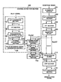
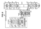
- FIG. 9 shows a configuration of a channel estimation device and equalization device (frequency domain equalizer) used in a conventional radio system.
- the channel estimation device and equalization device include a GI (Guard Interval) removal section 101 , an S/P (Serial/Parallel) conversion section 102 , an FFT (Fast Fourier Transform) section 103 , a reception filter 104 , a channel estimation section 105 , a weight calculation section 113 , an equalization filter 114 , an IFFT (Inverse Fast Fourier Transform) section 115 , and a P/S (Parallel/Serial) conversion section 116 .
- GI Guard Interval
- S/P Serial/Parallel
- FFT Fast Fourier Transform
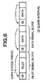
- a radio frame signal is composed of a plurality of pilot signal blocks or a plurality of data signal blocks.
- a pilot signal block is placed at the head of the radio frame signal followed by a plurality of successive data signal blocks.
- a GI is added to the head of each block before FFT processing in order to avoid multipath interference from a block preceding each block.
- a cyclic prefix is typically used which adds the last data in each block to the head thereof.
- the GI removal section 101 receives a reception signal and removes a portion of the reception signal corresponding to GI.
- the S/P conversion section 102 performs a serial to parallel conversion of the reception signal from which the GI has been removed by the GI removal section 101 .
- the FFT section 103 is supplied with the reception signal that has been subjected to the S/P conversion by S/P conversion section 102 and applies N FFT (N FFT is an integer equal to or more than 2 and power of 2)-point FFT to the reception signal for conversion into a signal in a frequency domain.
- the reception filter 104 limits the band of the reception signal within the frequency domain so as to shape the waveform and suppress noise.
- a raised cosine roll-off filter is typically used.
- filtering of the reception signal is performed through frequency domain signal processing, the filtering may be performed prior to the processing of the FFT section 103 through time domain signal processing.
- the channel estimation section 105 performs frequency domain correlation processing between a pilot reception signal and a pilot reference signal to estimate channel characteristics.
- the channel estimation section 105 includes a pilot reference signal generation section 106 , a correlation processing section 111 , and a noise suppression section 112 .
- the pilot reference signal generation section 106 includes a S/P conversion section 107 , an FFT section 108 , a transmission/reception filter 109 , and a ZF (Zero Forcing)/MMSE (Minimum Mean Square Error) calculation section 110 .
- the S/P conversion section 107 performs a serial to parallel conversion of a pilot code.
- the FFT section 108 applies FFT to the pilot code that has been subjected to the S/P conversion by the S/P conversion section 107 to convert the pilot code into a frequency domain.
- the transmission/reception filter 109 passes a frequency domain signal of the pilot code though a transmission/reception filter. Although, in the configuration shown in FIG. 9 , filtering of the frequency domain signal of the pilot code is performed through frequency domain signal processing, the filtering may be performed prior to the processing of the FFT section 108 through time domain signal processing. The processing of the transmission/reception filter 109 may be omitted in order to reduce the amount of calculation processing.
- the ZF/MMSE calculation section 110 uses a signal output from the transmission/reception filter 109 to calculate a pilot reference signal used in the correlation processing.
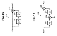
- FIG. 10 shows a configuration of the ZF calculation section 110 that calculates a pilot reference signal for use in ZF channel estimation.
- the ZF calculation section 110 includes a square calculation section 121 , an inverse number calculation section 122 , and a multiplication section 123 .
- a pilot reference signal X(m) (1 ⁇ m ⁇ N FFT ) of a sub-carrier m required for performing the ZF channel estimation is represented by the following equation.
- C(m) is the output signal of the transmission/reception filter 109 .
- X ⁇ ( m ) C ⁇ ( m ) ⁇ C ⁇ ( m ) ⁇ 2 + ⁇ 2 ( 2 ) where ⁇ 2 is noise power.
- P RX (m) is the pilot reception signal, the band of which has been limited by reception filter 104
- a suffix * is a complex conjugation.
- code characteristics of the pilot reception signal can be canceled, together with the characteristics of the transmission/reception filter, whereby only the channel characteristics H (m) can be detected.
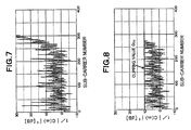
- the size of the frequency domain signal of the pilot code is not constant, noise enhancement occurs, degrading the channel estimation accuracy.
- FIG. 7 shows gain characteristics (1/
- the gain of the pilot reference signal is determined such that the mean square error of the channel estimation value becomes minimum, which improves the channel estimation accuracy as compared with the case of the ZF channel estimation.
- the noise suppression section 112 suppresses the noise of the channel estimation value estimated by the correlation processing section 111 to thereby improve the ratio of signal power to noise power (S/N).
- the noise suppression section 112 may employ a method of averaging adjacent sub-carriers, a method of temporarily converting a channel estimation value into an estimation value in a time domain to remove a noise path, or the like.
- the equalization filter 114 is supplied with the equalization weight calculated by the weight calculation section 113 and reception signal, the band of which has been limited by the reception filter 104 and equalizes, in the frequency domain, the reception signal by multiplying the reception signal by the equalization weight for each sub-carrier.
- a signal Y(m) (1 ⁇ m ⁇ N FFT ) equalized by the equalization filter 114 is represented by the following equation.
- Non-patent Document 1 D. Falconer, S. L. Ariyavisitakul, A. Benyamin-Seeyar, and B. Eidson, “Frequency Domain Equalization for Single-Carrier Broadband Wireless Access,” IEEE Commun. Mag., vol. 40, no. 4, pp. 58-66, April 2002.
- the noise enhancement occurs if the size of the frequency domain signal of the pilot code is not constant, degrading the channel estimation accuracy, which may result in degradation of equalization characteristics.
- the channel estimation accuracy is increased as compared with the ZF approach, while the amount of calculation processing is increased. This is because that, since the pilot code is not changed during communication, it is sufficient to generate only once the pilot reference signal prior to communication in the case where the ZF channel estimation is performed, while it is necessary, in the MMSE transmission estimation, to perform processing of the noise addition section 124 , inverse number calculation section 122 , and multiplication section 123 shown in FIG. 11 every time the noise power value is updated so as to calculate the pilot reference signal.
- An object of the present invention is to provide a channel estimation device and an equalization device that convert a single carrier signal into a frequency domain signal and perform channel estimation and equalization processing through frequency domain signal processing, in which by clipping the gain of a pilot reference signal for use in correlation processing of a channel estimation section to a predetermined value, high channel estimation accuracy can be achieved with less amount of calculation processing.
- a channel estimation device that converts a single carrier signal into a frequency domain signal and estimates channel characteristics through frequency domain signal processing, characterized by comprising: a ZF calculation/clipping processing section that uses a signal obtained by converting a pilot code into a frequency domain to calculate a pilot reference signal according to a Zero Forcing (ZF) method and clips the gain of the calculated pilot reference signal to a predetermined value to generate a clipped pilot reference signal; and a correlation processing section that performs correlation between a pilot reception signal in the frequency domain and clipped pilot reference signal to estimate channel characteristics of the frequency domain.
- ZF Zero Forcing
- an equalization device that converts a single carrier signal into a frequency domain signal and performs equalization processing through frequency domain signal processing, characterized by comprising: a ZF calculation/clipping processing section that uses a signal obtained by converting a pilot code into a frequency domain to calculate a pilot reference signal according to a Zero Forcing (ZF) method and clips the gain of the calculated pilot reference signal to a predetermined value to generate a clipped pilot reference signal; a correlation processing section that performs correlation between a pilot reception signal in the frequency domain and clipped pilot reference signal to estimate channel characteristics of the frequency domain; a weight calculation section that calculates an equalization weight based on the channel characteristics of the frequency domain; and an equalization filter that performs equalization processing of a frequency domain reception signal using the equalization weight.
- ZF Zero Forcing
- the ZF calculation/clipping processing section may change, in an adaptive manner, the predetermined value of the clipping in inversely proportional to a noise power value.
- the ZF calculation/clipping processing section may previously calculate a plurality of pilot reference signal candidates clipped to different predetermined values and select, from the plurality of pilot reference signal candidates, a pilot reference signal clipped to an optimum value based on a value inversely proportional to the noise power value.
- the weight calculation section may calculate the equalization weight based on an MMSE (Minimum Mean Square Error) method or a ZF method
- a channel estimation device and an equalization device that convert a single carrier signal into a frequency domain signal and perform channel estimation and equalization processing through frequency domain signal processing, in which by clipping the gain of a pilot reference signal for use in correlation processing of a channel estimation section to a predetermined value, high channel estimation accuracy can be achieved with less amount of calculation processing.
- FIG. 1 is configuration view of a channel estimation device and an equalization device used in a radio system according to a first example of the present invention
- FIG. 2 is a block diagram showing a configuration of a ZF calculation/clipping processing section in the first example of the present invention
- FIG. 3 is a block diagram showing a configuration of a ZF calculation/clipping processing section in a second example of the present invention
- FIG. 4 is a block diagram showing a configuration of a ZF calculation/clipping processing section in a third example of the present invention.
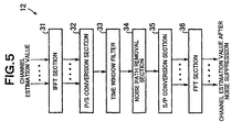
- FIG. 5 is a block diagram showing a configuration example of a noise suppression section in the first example of the present invention.
- FIG. 6 is a view showing an example of a radio frame format in the case where a frequency domain equalizer is used in a conventional example
- FIG. 7 is a view showing gain characteristics of a pilot reference signal obtained in the case where a random code is used as a pilot code in the conventional example
- FIG. 9 is a block diagram showing a channel estimation device and an equalization device according to the conventional example.
- FIG. 10 is a configuration of a ZF calculation section in a ZF/MMSE calculation section in the conventional example.
- FIG. 11 is a configuration of an MMSE calculation section in the ZF/MMSE calculation section in the conventional example.
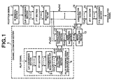
- FIG. 1 is a configuration view of a first example of a channel estimation device and an equalization device according to the present invention.
- the channel estimation device and equalization device used in a radio system according to the present example shown in FIG. 1 include a GI removal section 1 , an S/P conversion section 2 , an FFT section 3 , a reception filter 4 , a channel estimation section 5 , a weight calculation section 13 , an equalization filter 14 , an IFFT section 15 , and a P/S conversion section 16 .
- the present example is featured in that the gain of a pilot reference signal for use in correlation processing of the channel estimation section 5 is clipped to a predetermined value.
- the GI removal section 1 receives a reception signal and removes a portion of the reception signal corresponding to GI.
- the S/P conversion section 2 performs a serial to parallel conversion of the reception signal from which the GI has been removed by GI removal section 1 .
- the FFT section 3 is supplied with the reception signal that has been subjected to the S/P conversion by the S/P conversion section 2 and applies NFFT (NFFT is an integer equal to or more than 2 and power of 2)-point FFT to the reception signal for conversion into a signal in a frequency domain.
- the pilot reference signal generation section 6 includes a S/P conversion section 7 , an FFT section 8 , a transmission/reception filter 9 , and a ZF calculation/clipping processing section 10 .
- the S/P conversion section 7 performs a serial to parallel conversion of a pilot code.
- the FFT section 8 applies FFT to the pilot code that has been subjected to the S/P conversion by the S/P conversion section 7 to convert the pilot code into a frequency domain.
- the transmission/reception filter 9 passes a frequency domain signal of the pilot code through a transmission/reception filter. Although, in the configuration shown in FIG. 1 , filtering of the frequency domain signal of the pilot code is performed through frequency domain signal processing, the filtering may be performed prior to the processing of the FFT section 8 through time domain signal processing.
- the processing of the transmission/reception filter 9 may be omitted in order to reduce the amount of calculation processing.
- the ZF calculation/clipping processing section 10 includes a square calculation section 21 , an inverse number calculation section 22 , a clipping section 24 and a multiplication section 23 .
- the clipping section 24 clips the gain (1/
- a pilot reference signal X(m) (1 ⁇ m ⁇ N FFT ) of a sub-carrier m required for performing channel estimation is represented by the following equation.
- FIG. 8 shows the gain characteristics (G(m) characteristics) of the pilot reference signal clipped to a clipping value G TH of 10 dB.
- G(m) characteristics the gain characteristics of the pilot reference signal clipped to a clipping value G TH of 10 dB.
- the noise suppression section 12 suppresses the noise of the channel estimation value estimated by the correlation processing section 11 to thereby improve the ratio of signal power to noise power (S/N).
- the noise suppression section 12 may employ a method of averaging adjacent sub-carriers, a method of temporarily converting a channel estimation value into an estimation value in a time domain to remove a noise path, or the like.
- the IFFT section 31 converts the channel estimation value estimated by the correlation processing section 11 into a channel response in the time domain.
- the P/S conversion section 32 performs a parallel to serial conversion of the channel response.
- the time window filter 33 passes the channel response that has been subjected to the P/S conversion through a time window filter to thereby suppress noise. For example, under the assumption that the channel response values are within the GI width, a part of the path other than a section corresponding to the GI width is removed (substituted with 0) as a noise path from the respective values (paths) of the channel response.
- the IFFT section 15 is supplied with the equalized signal in the frequency domain output from the equalization filter 14 and applies N FFT -point IFFT to the equalized signal for conversion into a signal in the time domain.
- the P/S conversion section 16 performs a parallel to serial conversion of the signal in the time domain so as to output it as a demodulated signal.
- FIG. 3 shows a configuration of the ZF calculation/clipping processing section 10 in the second example.
- the ZF calculation/clipping processing section 10 shown in FIG. 3 includes a square calculation section 21 , an inverse number calculation section 22 , a clipping section 24 and a multiplication section 23 .
- the clipping section 24 clips the gain (1/
- the clipping value G TH is set as follows.
- the gain of the pilot reference signal is clipped based on the noise power value in an adaptive manner, thereby improving the channel estimation accuracy as compared with the ZF channel estimation.
- the channel estimation accuracy comparable to the MMSE channel estimation.
- processing of the inverse number calculation section 22 can be omitted, so that it is possible to reduce the amount of calculation as compared with the MMSE channel estimation.
- the gain of the pilot reference signal calculated using the ZF method is clipped based on the noise power value in an adaptive manner, thereby achieving the channel estimation accuracy comparable to the MMSE channel estimation while reducing the amount of calculation processing as compared with the MMSE channel estimation.
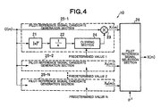
- the third example differs from the first and second examples only in the operation of the ZF calculation/clipping processing section 10 .
- the operations of the other components are same as those of the first and second examples, and descriptions thereof are omitted here.
- FIG. 4 shows a configuration of the ZF calculation/clipping processing section 10 in the third example.
- the ZF calculation/clipping processing section 10 shown in FIG. 4 includes N (N is an integer equal to or more than 2) pilot reference signal candidate generation sections 25 - 1 to 25 -N and a pilot reference signal selection section 26 .
- N is an integer equal to or more than 2
- pilot reference signal candidate generation sections 25 - 1 to 25 -N has the same configuration as that of the ZF calculation/clipping processing section shown in FIG. 2 .
- the pilot reference signal candidate generation sections 25 - 1 to 25 -N clip the gain (1/
- the present example by calculating a plurality of pilot reference signal candidates in which the gain of the pilot reference signal is clipped to different predetermined values and selecting a pilot reference signal clipped to an optimum value based on the noise power value ⁇ 2 , it is possible to achieve the channel estimation accuracy comparable to the MMSE channel estimation. Further, it is sufficient to generate the plurality of pilot reference signals only once prior to communication, so that an increase in the amount of calculation processing can be avoided.
- the present example by calculating a plurality of pilot reference signal candidates in which the gain of the pilot reference signal calculated using the ZF method is clipped to different predetermined values and selecting a pilot reference signal clipped to an optimum value based on the noise power value, it is possible to achieve the channel estimation accuracy comparable to the MMSE channel estimation while avoiding an increase in the amount of calculation processing required starting from the ZF channel estimation step.
- the present invention can be applied to a channel estimation device and an equalization device used in a radio system.
- the present invention can suitably be applied to a channel estimation device and an equalization device that convert a single carrier signal into a frequency domain signal and perform channel estimation and equalization processing through frequency domain signal processing.
Abstract
Description
where σ2 is noise power.
H(m)=X*(m)P RX(m) (3)
Y(m)=W*(m)D RX(m) (5)
- 1, 101: GI removal section
- 2, 7, 35, 102, 107: S/P conversion section
- 3, 8, 36, 103, 108: FFT section
- 4, 104: Reception filter
- 5, 105: Channel estimation section
- 6, 106: Pilot reference signal generation section
- 9, 109: Transmission/reception filter
- 10: ZF calculation/clipping processing section
- 11, 111: Correlation processing section
- 12, 112: Noise suppression section
- 13, 113: Weight calculation section
- 14, 114: Equalization filter
- 15, 31, 115: IFFT section
- 16, 32, 116: P/S conversion section
- 21, 121: Square calculation section
- 22, 122: Inverse number calculation section
- 23, 123: Multiplication section
- 24: Clipping section
- 25-1 to N: Pilot reference signal candidate generation section
- 26: Pilot reference signal selection section
- 33: Time window filter
- 34: Noise path removal section
- 110: ZF/MMSE calculation section
- 124: Noise addition section
X(m)=G(m)C(m) (6)
where G(m) is the gain of the pilot reference signal that has been subjected to the clipping, which is calculated according to the following equation.
[Numeral 7]
H(m)=X*(m)P RX(m) (8)
Y(m)=W*(m)D RX(m) (10)
Claims (18)
Applications Claiming Priority (3)
| Application Number | Priority Date | Filing Date | Title |
|---|---|---|---|
| JP2006-015051 | 2006-01-24 | ||
| JP2006015051 | 2006-01-24 | ||
| PCT/JP2007/050962 WO2007086364A1 (en) | 2006-01-24 | 2007-01-23 | Transmission path estimation device, equalization device, and radio system |
Publications (2)
| Publication Number | Publication Date |
|---|---|
| US20090022253A1 US20090022253A1 (en) | 2009-01-22 |
| US8121216B2 true US8121216B2 (en) | 2012-02-21 |
Family
ID=38309154
Family Applications (1)
| Application Number | Title | Priority Date | Filing Date |
|---|---|---|---|
| US12/162,126 Expired - Fee Related US8121216B2 (en) | 2006-01-24 | 2007-01-23 | Channel estimation device, equalization device, and radio system |
Country Status (6)
| Country | Link |
|---|---|
| US (1) | US8121216B2 (en) |
| JP (1) | JP4780419B2 (en) |
| KR (1) | KR100966942B1 (en) |
| CN (1) | CN101375521B (en) |
| GB (1) | GB2448097B (en) |
| WO (1) | WO2007086364A1 (en) |
Cited By (3)
| Publication number | Priority date | Publication date | Assignee | Title |
|---|---|---|---|---|
| US20110268169A1 (en) * | 2010-04-28 | 2011-11-03 | Kabushiki Kaisha Toshiba | Equalization apparatus and broadcasting receiving apparatus |
| US20170331599A1 (en) * | 2016-05-13 | 2017-11-16 | Industrial Technology Research Institute | Wireless communication apparatus and the method thereof |
| US20230344695A1 (en) * | 2020-02-14 | 2023-10-26 | Huawei Technologies Co., Ltd. | Multi-Rate Crest Factor Reduction |
Families Citing this family (5)
| Publication number | Priority date | Publication date | Assignee | Title |
|---|---|---|---|---|
| US20090060063A1 (en) * | 2007-08-31 | 2009-03-05 | Telefonaktiebolaget Lm Ericsson (Publ) | Method and Apparatus for Robust Control Signaling Distribution in OFDM Systems |
| EP2214362B1 (en) * | 2009-02-02 | 2012-08-01 | Sony Corporation | Receiving apparatus with frequency domain equalizer |
| JP5697483B2 (en) * | 2011-02-23 | 2015-04-08 | 京セラ株式会社 | Wireless communication system, wireless base station, and communication control method |
| CN103856240A (en) * | 2012-12-06 | 2014-06-11 | 华为技术有限公司 | Signal detection method and device, and receiver |
| US11432369B2 (en) * | 2018-06-19 | 2022-08-30 | Apple Inc. | Reference signal and control information processing in 5G-NR wireless systems |
Citations (10)
| Publication number | Priority date | Publication date | Assignee | Title |
|---|---|---|---|---|
| US5970060A (en) * | 1995-10-06 | 1999-10-19 | Siemens Aktiengesellschaft | Method and system for radio transmission of digital signals |
| CN1404675A (en) | 2000-02-22 | 2003-03-19 | 皇家菲利浦电子有限公司 | Multicarrier receiver with channel estimator |
| CN1567762A (en) | 2003-06-10 | 2005-01-19 | 北京邮电大学 | A channel estimation method adapted for OFDMA system |
| JP2005051404A (en) | 2003-07-31 | 2005-02-24 | Kddi Corp | Transmission line characteristic estimation device and computer program |
| JP2005151447A (en) | 2003-11-19 | 2005-06-09 | Matsushita Electric Ind Co Ltd | Ofdm receiver |
| JP2005167674A (en) | 2003-12-03 | 2005-06-23 | Toyota Central Res & Dev Lab Inc | Method for compensating intra-symbol time variation in multicarrier reception, apparatus for compensating intra-symbol time variation in multicarrier receiving apparatus, and multicarrier receiving apparatus including the same |
| JP2005223698A (en) | 2004-02-06 | 2005-08-18 | Kddi Corp | Transmission line characteristic estimating device and computer program |
| JP2005244291A (en) | 2004-02-24 | 2005-09-08 | Kddi Corp | Transmission line characteristics estimator and computer program |
| JP2005328311A (en) | 2004-05-13 | 2005-11-24 | Ntt Docomo Inc | Noise-power estimating device, method for estimating noise power and signal detector |
| US20060203932A1 (en) * | 2005-03-07 | 2006-09-14 | Ravi Palanki | Pilot transmission and channel estimation for a communication system utilizing frequency division multiplexing |
Family Cites Families (4)
| Publication number | Priority date | Publication date | Assignee | Title |
|---|---|---|---|---|
| KR100363254B1 (en) * | 2000-02-18 | 2002-11-30 | 삼성전자 주식회사 | Apparatus and method for transmitting and receiving orthogonal frequency division multiplexing signal |
| CN1207908C (en) * | 2002-08-16 | 2005-06-22 | 清华大学 | Method based on slide window for estimating and equalizing channels of block signals containing pilot |
| KR100542114B1 (en) | 2003-03-27 | 2006-01-10 | 주식회사 케이티프리텔 | Wireless wireless communication system based on the orthogonal frequency division multiplexing and method for channel compensation |
| KR100555520B1 (en) * | 2003-10-28 | 2006-03-03 | 삼성전자주식회사 | Apparatus compensating nonlinearly distorted multicarrier signals, multicarrier signals receiver having it and method therefor |
-
2007
- 2007-01-23 GB GB0813565A patent/GB2448097B/en not_active Expired - Fee Related
- 2007-01-23 US US12/162,126 patent/US8121216B2/en not_active Expired - Fee Related
- 2007-01-23 JP JP2007555936A patent/JP4780419B2/en not_active Expired - Fee Related
- 2007-01-23 CN CN2007800033696A patent/CN101375521B/en not_active Expired - Fee Related
- 2007-01-23 KR KR1020087017898A patent/KR100966942B1/en active IP Right Grant
- 2007-01-23 WO PCT/JP2007/050962 patent/WO2007086364A1/en active Application Filing
Patent Citations (10)
| Publication number | Priority date | Publication date | Assignee | Title |
|---|---|---|---|---|
| US5970060A (en) * | 1995-10-06 | 1999-10-19 | Siemens Aktiengesellschaft | Method and system for radio transmission of digital signals |
| CN1404675A (en) | 2000-02-22 | 2003-03-19 | 皇家菲利浦电子有限公司 | Multicarrier receiver with channel estimator |
| CN1567762A (en) | 2003-06-10 | 2005-01-19 | 北京邮电大学 | A channel estimation method adapted for OFDMA system |
| JP2005051404A (en) | 2003-07-31 | 2005-02-24 | Kddi Corp | Transmission line characteristic estimation device and computer program |
| JP2005151447A (en) | 2003-11-19 | 2005-06-09 | Matsushita Electric Ind Co Ltd | Ofdm receiver |
| JP2005167674A (en) | 2003-12-03 | 2005-06-23 | Toyota Central Res & Dev Lab Inc | Method for compensating intra-symbol time variation in multicarrier reception, apparatus for compensating intra-symbol time variation in multicarrier receiving apparatus, and multicarrier receiving apparatus including the same |
| JP2005223698A (en) | 2004-02-06 | 2005-08-18 | Kddi Corp | Transmission line characteristic estimating device and computer program |
| JP2005244291A (en) | 2004-02-24 | 2005-09-08 | Kddi Corp | Transmission line characteristics estimator and computer program |
| JP2005328311A (en) | 2004-05-13 | 2005-11-24 | Ntt Docomo Inc | Noise-power estimating device, method for estimating noise power and signal detector |
| US20060203932A1 (en) * | 2005-03-07 | 2006-09-14 | Ravi Palanki | Pilot transmission and channel estimation for a communication system utilizing frequency division multiplexing |
Non-Patent Citations (2)
| Title |
|---|
| David Falconer, et al.; "Frequency Domain Equalization for Single-Carrier Broadband Wireless Systems"; Wideband Wireless Access Technologies to Broadband Internet; IEEE Communications Magazine; Apr. 2002; pp. 58-66. |
| Noriaki Miyazaki, et al.; "A Study on Applying Frequency Domain Equalization to Single Carrier CDMA Cellular System (Part 1)"; 2004; p. 639; The Institute of Electronics, Information and Communication Engineers. |
Cited By (5)
| Publication number | Priority date | Publication date | Assignee | Title |
|---|---|---|---|---|
| US20110268169A1 (en) * | 2010-04-28 | 2011-11-03 | Kabushiki Kaisha Toshiba | Equalization apparatus and broadcasting receiving apparatus |
| US20170331599A1 (en) * | 2016-05-13 | 2017-11-16 | Industrial Technology Research Institute | Wireless communication apparatus and the method thereof |
| US9942011B2 (en) * | 2016-05-13 | 2018-04-10 | Industrial Technology Research Institute | Wireless communication apparatus and the method thereof |
| US20230344695A1 (en) * | 2020-02-14 | 2023-10-26 | Huawei Technologies Co., Ltd. | Multi-Rate Crest Factor Reduction |
| US11956111B2 (en) * | 2020-02-14 | 2024-04-09 | Huawei Technologies Co., Ltd. | Multi-rate crest factor reduction |
Also Published As
| Publication number | Publication date |
|---|---|
| KR100966942B1 (en) | 2010-06-30 |
| JPWO2007086364A1 (en) | 2009-06-18 |
| CN101375521A (en) | 2009-02-25 |
| US20090022253A1 (en) | 2009-01-22 |
| GB0813565D0 (en) | 2008-09-03 |
| KR20080086906A (en) | 2008-09-26 |
| WO2007086364A1 (en) | 2007-08-02 |
| JP4780419B2 (en) | 2011-09-28 |
| CN101375521B (en) | 2013-03-27 |
| GB2448097A (en) | 2008-10-01 |
| GB2448097B (en) | 2010-12-08 |
Similar Documents
| Publication | Publication Date | Title |
|---|---|---|
| US8121216B2 (en) | Channel estimation device, equalization device, and radio system | |
| US8351553B2 (en) | MIMO receiving apparatus and receiving method | |
| US7532567B2 (en) | Radio communication system, radio transmitter and radio receiver | |
| US8406355B2 (en) | Method and apparatus for channel estimation in OFDM | |
| US8094709B2 (en) | Equalizer and equalization method | |
| US8064328B2 (en) | Channel estimation device | |
| EP2120359B1 (en) | Channel estimation device, equalization device, and equalization method in the estimation | |
| US8275053B2 (en) | Apparatus and method of estimating channel based on channel delay spread in mobile communication system | |
| US8576934B2 (en) | Receiving device, receiving method, and program | |
| US8619744B2 (en) | Reception method and receiver | |
| JP2006262039A (en) | Propagation path estimation method and propagation path estimation apparatus | |
| US8457225B2 (en) | Methods relating to channel estimation | |
| US8374298B2 (en) | Receiving apparatus and method | |
| JP2008028515A (en) | Receiver, receiving method, and program | |
| EP2037607A1 (en) | Receiver and propagation path estimation method | |
| JP5308438B2 (en) | Interference estimation method for orthogonal pilot pattern | |
| US8477865B2 (en) | MIMO receiving apparatus and method | |
| KR100835164B1 (en) | Apparatus and method for channel estimate in broadband wireless access communication system | |
| WO2009093332A1 (en) | Reception processing method and reception device | |
| KR20090013957A (en) | Apparatus and method for compensation of channel impulse response estimation error in orthogonal frequency division multiplexing systems | |
| US7864901B2 (en) | System, apparatus, and method for cancelling interferences of received signals |
Legal Events
| Date | Code | Title | Description |
|---|---|---|---|
| AS | Assignment |
Owner name: NEC CORPORATION, JAPAN Free format text: ASSIGNMENT OF ASSIGNORS INTEREST;ASSIGNORS:YOSHIDA, SHOUSEI;KIMATA, MASAYUKI;REEL/FRAME:021289/0043 Effective date: 20080618 |
|
| STCF | Information on status: patent grant |
Free format text: PATENTED CASE |
|
| FPAY | Fee payment |
Year of fee payment: 4 |
|
| FEPP | Fee payment procedure |
Free format text: MAINTENANCE FEE REMINDER MAILED (ORIGINAL EVENT CODE: REM.); ENTITY STATUS OF PATENT OWNER: LARGE ENTITY |
|
| LAPS | Lapse for failure to pay maintenance fees |
Free format text: PATENT EXPIRED FOR FAILURE TO PAY MAINTENANCE FEES (ORIGINAL EVENT CODE: EXP.); ENTITY STATUS OF PATENT OWNER: LARGE ENTITY |
|
| STCH | Information on status: patent discontinuation |
Free format text: PATENT EXPIRED DUE TO NONPAYMENT OF MAINTENANCE FEES UNDER 37 CFR 1.362 |
|
| FP | Lapsed due to failure to pay maintenance fee |
Effective date: 20200221 |