US8110248B2 - Fuel cell structure and method of manufacturing same - Google Patents
Fuel cell structure and method of manufacturing same Download PDFInfo
- Publication number
- US8110248B2 US8110248B2 US11/884,234 US88423406A US8110248B2 US 8110248 B2 US8110248 B2 US 8110248B2 US 88423406 A US88423406 A US 88423406A US 8110248 B2 US8110248 B2 US 8110248B2
- Authority
- US
- United States
- Prior art keywords
- fuel cell
- diffusion layer
- catalyst layer
- nano
- manufacturing
- Prior art date
- Legal status (The legal status is an assumption and is not a legal conclusion. Google has not performed a legal analysis and makes no representation as to the accuracy of the status listed.)
- Expired - Fee Related, expires
Links
Images


Classifications
-
- H—ELECTRICITY
- H01—ELECTRIC ELEMENTS
- H01M—PROCESSES OR MEANS, e.g. BATTERIES, FOR THE DIRECT CONVERSION OF CHEMICAL ENERGY INTO ELECTRICAL ENERGY
- H01M8/00—Fuel cells; Manufacture thereof
- H01M8/02—Details
- H01M8/0202—Collectors; Separators, e.g. bipolar separators; Interconnectors
- H01M8/023—Porous and characterised by the material
- H01M8/0234—Carbonaceous material
-
- H—ELECTRICITY
- H01—ELECTRIC ELEMENTS
- H01M—PROCESSES OR MEANS, e.g. BATTERIES, FOR THE DIRECT CONVERSION OF CHEMICAL ENERGY INTO ELECTRICAL ENERGY
- H01M4/00—Electrodes
- H01M4/86—Inert electrodes with catalytic activity, e.g. for fuel cells
- H01M4/88—Processes of manufacture
- H01M4/8817—Treatment of supports before application of the catalytic active composition
-
- H—ELECTRICITY
- H01—ELECTRIC ELEMENTS
- H01M—PROCESSES OR MEANS, e.g. BATTERIES, FOR THE DIRECT CONVERSION OF CHEMICAL ENERGY INTO ELECTRICAL ENERGY
- H01M4/00—Electrodes
- H01M4/86—Inert electrodes with catalytic activity, e.g. for fuel cells
- H01M4/96—Carbon-based electrodes
-
- H—ELECTRICITY
- H01—ELECTRIC ELEMENTS
- H01M—PROCESSES OR MEANS, e.g. BATTERIES, FOR THE DIRECT CONVERSION OF CHEMICAL ENERGY INTO ELECTRICAL ENERGY
- H01M8/00—Fuel cells; Manufacture thereof
- H01M8/10—Fuel cells with solid electrolytes
- H01M2008/1095—Fuel cells with polymeric electrolytes
-
- Y—GENERAL TAGGING OF NEW TECHNOLOGICAL DEVELOPMENTS; GENERAL TAGGING OF CROSS-SECTIONAL TECHNOLOGIES SPANNING OVER SEVERAL SECTIONS OF THE IPC; TECHNICAL SUBJECTS COVERED BY FORMER USPC CROSS-REFERENCE ART COLLECTIONS [XRACs] AND DIGESTS
- Y02—TECHNOLOGIES OR APPLICATIONS FOR MITIGATION OR ADAPTATION AGAINST CLIMATE CHANGE
- Y02E—REDUCTION OF GREENHOUSE GAS [GHG] EMISSIONS, RELATED TO ENERGY GENERATION, TRANSMISSION OR DISTRIBUTION
- Y02E60/00—Enabling technologies; Technologies with a potential or indirect contribution to GHG emissions mitigation
- Y02E60/30—Hydrogen technology
- Y02E60/50—Fuel cells
-
- Y—GENERAL TAGGING OF NEW TECHNOLOGICAL DEVELOPMENTS; GENERAL TAGGING OF CROSS-SECTIONAL TECHNOLOGIES SPANNING OVER SEVERAL SECTIONS OF THE IPC; TECHNICAL SUBJECTS COVERED BY FORMER USPC CROSS-REFERENCE ART COLLECTIONS [XRACs] AND DIGESTS
- Y02—TECHNOLOGIES OR APPLICATIONS FOR MITIGATION OR ADAPTATION AGAINST CLIMATE CHANGE
- Y02P—CLIMATE CHANGE MITIGATION TECHNOLOGIES IN THE PRODUCTION OR PROCESSING OF GOODS
- Y02P70/00—Climate change mitigation technologies in the production process for final industrial or consumer products
- Y02P70/50—Manufacturing or production processes characterised by the final manufactured product
Definitions
- the present invention relates to a polymer electrolyte fuel cell structure and a method of manufacturing the same whereby the manufacturing process can be simplified and the amount of catalytic precious metal can be reduced, which leads to a significant decrease in cost.
- polymer electrolyte fuel cells There are many types of fuel cell depending on the type of electrolyte used, such as polymer, phosphoric acid, solid oxide, molten carbonate, and alkaline.
- polymer electrolyte fuel cells have lower operating temperature and shorter startup time than other types of fuel cell. They are also easier to produce high output, expected to be reduced in size and weight, and resistant to vibration. For these reasons, the polymer electrolyte fuel cell is suitable as a power source for mobile objects.
- Fuel cells generally employ a perfluorosulfonic acid membrane having a high proton conductivity.
- ion-exchange membrane currently used in polymer electrolyte fuel cells include perfluorocarbon sulfonic acid membranes such as Nafion (registered trademark) by DuPont, Flemion (registered trademark) by Asahi Glass Co., Ltd, Aciplex (registered trademark) by Asahi Kasei Corporation.
- a membrane-electrode assembly which has a structure such that electrode catalyst layers having a fuel oxidizing capacity or an oxidant reducing capacity are disposed on both sides of the ion-exchange membrane, on the outside of which gas diffusion layers are further disposed.
- the structure includes an ion-exchange membrane consisting of a polymer electrolyte membrane that selectively transports hydrogen ion, on each side of which the electrode catalyst layer is formed.
- the electrode catalyst layer comprises, as a main component, a carbon powder supporting a platinum group metal catalyst.
- the gas diffusion layer which has both a fuel gas permeability and electron conductivity, is formed.
- the gas diffusion layer consists of a substrate of carbon paper or carbon cloth on which a film of a paste containing a powder of fluorine resin, silicon, carbon or the like is formed.
- the aforementioned electrode catalyst layer and the gas diffusion layer are collectively referred to as an electrode.
- a gas sealing member or a gasket is disposed around the electrode in such a manner as to sandwich the ion-exchange membrane.
- the gas sealing member, gasket, electrode, and ion-exchange membrane are assembled in an integrated manner beforehand, into what is called a membrane-electrode assembly (MEA).
- an electrically conductive and airtight separator is disposed for mechanically fixing the assembly and electrically connecting adjacent MEAs to each other in series.
- a portion of the separator that is in contact with the MEA is formed with a gas channel for supplying a reaction gas to the electrode surface and to carry produced gas or excess gas away. While the gas channel can be provided separately from the separator, generally it is formed by providing a groove in the surface of the separator.
- Such structure consisting of the MEA fixed by means of a pair of the separators is used as a single cell, which is the basic unit.
- a fuel cell By connecting a plurality of such single cells in series and arranging a manifold, which is a piping jig for the supply of fuel gas, a fuel cell is constructed.
- manufacture of a polymer electrolyte fuel cell particularly the electrode consisting of an electrode catalyst layer and a gas diffusion layer, requires complex process steps and technology.
- the carbon powder supporting a platinum group metal catalyst does not necessarily have a large specific surface area, the amount of the supported platinum group metal catalyst is large, inevitably resulting in high cost.
- the electrode catalyst layer (either a cathode catalyst layer or an anode catalyst layer) to retain a sufficient amount of catalyst particle for obtaining the catalytic function
- electron conductivity is required between the electrode catalyst layer and the separator, which is a current collector
- proton conductivity is required between the electrode catalyst layer and the electrolyte membrane. Therefore, conventionally a catalyst layer on the order of several 10 g/m has been formed of a mixture of catalyst-supported conductive particle having a particle diameter on the order of 50 nm and proton conductor.
- the electrons formed in the catalyst near the electrolyte membrane do not reach the current collector unless they move between a plurality of conductive particles.
- the area of contact between the conductive particles is small; in some cases, the electric resistance between the conductive particles is high because of the presence of the proton conductivity material between the particles.
- the electron conductivity between the current collector and the electrode catalyst layer is low, resulting in a decrease in the generating efficiency of the fuel cell.
- the electron conductivity between the current collector and the electrode catalyst layer can be increased by increasing the density of the catalyst layer; however, increasing the density of the catalyst layer leads to a decrease in the dispersibility of fuel or oxidant into the catalyst layer, thereby making it impossible to fully exploit the catalytic function of the catalyst particle.
- JP Patent Publication (Kokai) No. 2002-298861 A discloses an invention of an electrode for fuel cells, its object being the provision of a fuel cell having a high generation efficiency, a fuel cell electrode for realizing such fuel cell, and a method for manufacturing a fuel cell electrode achieving such fuel cell.
- This electrode comprises a current collector made of a conductive porous material, and a catalyst layer comprised of carbon nanofiber of which 50% or more of the tip portions has an angle of elevation of 45° or more with respect to the plane of the current collector, an electrode catalyst particle supported on the carbon nanofiber surface, and a proton conductor formed on the surface of the carbon nanofiber in contact with the electrode catalyst particle.
- JP Patent Publication (Kokai) No. 2002-298861 A makes it possible to simplify the process of manufacturing an electrode for fuel cells that is comprised of an electrode catalyst layer and a gas diffusion layer, and to improve the conductivity of the catalyst layer, whereby the fuel cell generation efficiency can be increased to some extent.
- the extent of improvement was not sufficient.
- an object of the invention to simplify the manufacturing process for an electrode for fuel cells comprising an electrode catalyst layer and a gas diffusion layer, to increase the electrical conductivity of the catalyst layer, to improve the diffusion efficiency of the diffusion layer, and thereby to improve the fuel cell generation efficiency.
- the present invention is based on the inventors' realization that the aforementioned objects can be achieved by using a specific carbonaceous porous material having a vapor-grown nano-size structure as a diffusion layer and/or a catalyst layer of the fuel cell electrode.
- the invention provides a fuel cell structure in which a carbonaceous porous material having a nano-size structure, such as carbon nanowall (CNW), is used as a diffusion layer and/or a catalyst layer.
- a carbonaceous porous material having a nano-size structure such as carbon nanowall (CNW)
- CNF carbon nanowall
- Carbon nanowall (CNW) is a carbonaceous porous material having a nano-size structure; its structure, method of manufacture, and so on will be described later.
- either the diffusion layer or the catalyst layer may be formed of a carbonaceous porous material having a nano-size structure, such as carbon nanowall (CNW). More preferably, both the diffusion layer and the catalyst layer are formed of a carbonaceous porous material having a nano-size structure, such as carbon nanowall (CNW).
- a side-wall of the diffusion layer comprising the carbonaceous porous material having a nano-size structure, such as carbon nanowall (CNW)
- a gas-diffusing opening portion By providing the gas-diffusing opening portion, gas diffusion can occur effectively.
- the invention provides a method of manufacturing a fuel cell structure.
- the method comprises the steps of: manufacturing a diffusion layer and a catalyst layer support by vapor-growing a carbonaceous porous material having a nano-size structure, such as carbon nanowall (CNW), on the surface of a separator and/or the surface of an electrolyte membrane; and distributing a catalyst component and an electrolyte in the catalyst layer support to manufacture a catalyst layer.
- CNW carbon nanowall
- This method can greatly simplify the process compared with conventional methods of manufacturing a fuel cell structure.
- the carbonaceous porous material having a nano-size structure, such as carbon nanowall (CNW) has a large specific surface area, the amount of platinum-group precious metal catalyst that is used can be reduced.
- the method preferably comprises the step of providing a nano-size opening in a side-wall of the diffusion layer to form a gas-diffusing opening portion, simultaneously with or after the step of manufacturing the diffusion layer and the catalyst layer support by vapor-growing the carbonaceous porous material having a nano-size structure, such as carbon nanowall (CNW), on the surface of the separator and/or the surface of the electrolyte membrane.
- a nano-size opening in a side-wall of the diffusion layer to form a gas-diffusing opening portion, simultaneously with or after the step of manufacturing the diffusion layer and the catalyst layer support by vapor-growing the carbonaceous porous material having a nano-size structure, such as carbon nanowall (CNW), on the surface of the separator and/or the surface of the electrolyte membrane.
- CCW carbon nanowall
- Preferable examples of the concrete method of forming the nano-size opening in the diffusion layer side-wall include plasma etching, FIB processing, laser processing, and oxidation treatment.
- the catalyst component that is supported on the carbon nanowall (CNW) in each layer can be varied.
- the function of the carbon nanowall (CNW) can be adapted for individual layers, whereby precise catalyst layers can be fabricated.
- the catalyst and the polymer electrolyte may be selected from a wide variety of known examples.
- the fuel cell comprising the fuel cell structure of the invention may be either planar or cylindrical.
- Examples of the carbonaceous porous material having a nano-size structure include graphite and amorphous, such as fullerene, carbon nanotube, carbon nanohom, and carbon nanoflake; in the invention, carbon nanowall is particularly preferable.
- the carbon nanowall used in the present invention is a two-dimensional carbon nanostructure. Typically, it has a wall-like structure in which walls rise upward from the surface of a substrate in a substantially uniform direction.
- Fullerene (such as C60) is a zero-dimensional carbon nanostructure.
- Carbon nanotube can be considered to be a one-dimensional carbon nanostructure.
- Carbon nanoflake is an aggregate of planar, two-dimensional small pieces similar to carbon nanowalls; like the petals of the rose, the individual pieces are not mutually connected; it is a carbon nanostructure whose directionality with respect to the substrate is inferior to the carbon nanowall.
- the carbon nanowall is a carbon nanostructure having totally different characteristics from the fullerene, carbon nanotube, carbon nanohom, or carbon nanoflake.
- the catalyst layer and the diffusion layer can be integrally formed.
- a nano-size structure such as carbon nanowall
- the catalyst layer and the diffusion layer can be integrally formed.
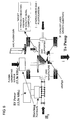
- FIG. 1 schematically shows an apparatus for the manufacture of CNW.
- FIG. 2 schematically shows SEM images of fabricated CNW.
- FIG. 3 schematically shows a structure of the invention.
- FIG. 4 schematically shows another structure of the invention.
- FIG. 5A shows an SEM image of the carbon nanowall (CNW) prior to FIB processing
- FIG. 5B shows an SEM image of the carbon nanowall (CNW) after FIB processing.
- FIG. 6 shows an apparatus for the diffusion layer-catalyst layer one-step manufacturing method of the invention.
- FIG. 7 illustrates an example of the method of providing openings by plasma etching.
- CCW carbon nanowall
- FIG. 1 schematically shows an apparatus for manufacturing CNW.
- FIG. 2 shows SEM images of CNW fabricated using the apparatus.
- an H radical and a reaction gas containing carbon such as CF 4 , C 2 F 6 , or CH 4 , are introduced between parallel plate electrodes in a chamber, and PECVD (plasma-enhanced chemical vapor deposition) is conducted.
- the substrate is preferably heated to about 500° C.
- the parallel plate electrodes are spaced apart from each other by 5 cm; between the plates, a capacitively coupled plasma is produced using an RF output apparatus of 13.56 MHz with an output of 100 W.
- the site of H radical growth is a quartz tube with length 200 mm and internal diameter 26 mm ⁇ , into which H 2 gas is introduced to produce an inductively coupled plasma using the RF output apparatus of 13.56 MHz with output 400 W.
- the flow rates of the source gas and the H 2 gas are 15 sccm and 30 sccm, respectively, and the pressure inside the chamber is 100 mTorr.
- the height of the CNW (CNW film thickness) grown in this system for 8 hours is 1.4 ⁇ m; this, however, is merely an example, and these passages do not limit the experiment conditions, facility, or results.
- FIG. 3 schematically shows a structure of the invention.
- the figure shows a catalyst layer by which a solid polymer membrane, not shown, is sandwiched, and a diffusion layer disposed on top thereof.
- a catalyst layer-diffusion layer integrated thin-film structure is shown in which both the catalyst layer and the diffusion layer are formed of carbon nanowall (CNW).
- CNW carbon nanowall
- a catalyst metal and a proton conductor are supported.
- FIG. 4 schematically shows another structure of the invention.
- FIG. 4 is similar to FIG. 3 in that the structure is a catalyst layer-diffusion layer integrated thin-film structure but differs from the structure of FIG. 3 in that nanometer-order openings are provided in the side-walls of the diffusion layer by plasma etching or FIB processing.
- plasma etching or FIB processing By providing the diffusion layer side-walls with the nanometer-order openings, gas dispersibility can be improved.
- FIG. 5A shows an SEM image of carbon nanowall (CNW) prior to FIB processing
- FIG. 5B shows an SEM image of carbon nanowall (CNW) after FIB processing. It can be seen that nanometer-order openings are provided in the side-walls of the carbon nanowall (CNW) by the FIB processing.
- a process is described for manufacturing a diffusion layer-catalyst layer integrated thin-film using a diffusion layer-catalyst layer one-step manufacturing method shown in FIG. 6 .
- CNW is used for both the diffusion layer and the catalyst layer.
- the proton conductor consists of a substance having a sulfonate group, phosphonate group, hydroxyl group, imidazole group, solid acid salt, tropolone, ionic liquid, or the like as a proton carrier.
- the catalyst material consists of: a group-8 metal, Cu, Ag, Au, or Ce; an organic metal compound of two or more of such substances; a metal salt or a metal of such substances; or a mixture thereof. These catalyst materials are merely examples, and other catalyst materials known in the art of fuel cell may be used.
- FIG. 7 shows an example of a method of providing openings by plasma etching.
- metal nanoparticles are deposited on the surface of CNW by means of arc discharge or plasma discharge, for example.
- the amount of deposit in this case is such that the CNW is visible.
- the CNW alone is etched, thereby providing nano-size through-holes.
- etching only proceeds in the portions of the gaps between the metal fine particles, so that through-holes are provided at those portions.
- the following advantages can be obtained: (1) since the diffusion layer-catalyst layer integrated thin-film can be formed at once in the same chamber, the number of steps can be reduced and therefore cost can be reduced; and (2) since the diffusion layer-catalyst layer is continuously formed, there is no contact resistance, whereby electricity generation loss in the fuel cell can be reduced.
- the use of a carbonaceous porous material having a nano-size structure, such as carbon nanowall, in the fuel cell structure allows the catalyst layer and the diffusion layer to be integrally formed.
- improved cell performance can be obtained.
- the invention contributes to the wide use of fuel cells.
Abstract
Description
Claims (5)
Applications Claiming Priority (3)
| Application Number | Priority Date | Filing Date | Title |
|---|---|---|---|
| JP2005036288A JP5074663B2 (en) | 2005-02-14 | 2005-02-14 | Manufacturing method of fuel cell structure |
| JP2005-036288 | 2005-02-14 | ||
| PCT/JP2006/302915 WO2006085698A1 (en) | 2005-02-14 | 2006-02-14 | Fuel cell structure and method for manufacturing same |
Publications (2)
| Publication Number | Publication Date |
|---|---|
| US20080187814A1 US20080187814A1 (en) | 2008-08-07 |
| US8110248B2 true US8110248B2 (en) | 2012-02-07 |
Family
ID=39676442
Family Applications (1)
| Application Number | Title | Priority Date | Filing Date |
|---|---|---|---|
| US11/884,234 Expired - Fee Related US8110248B2 (en) | 2005-02-14 | 2006-02-14 | Fuel cell structure and method of manufacturing same |
Country Status (1)
| Country | Link |
|---|---|
| US (1) | US8110248B2 (en) |
Families Citing this family (3)
| Publication number | Priority date | Publication date | Assignee | Title |
|---|---|---|---|---|
| JP4974495B2 (en) * | 2004-09-21 | 2012-07-11 | 勝 堀 | FUEL CELL SEPARATOR, FUEL CELL ELECTRODE STRUCTURE, METHOD FOR PRODUCING THEM, AND SOLID POLYMER FUEL CELL HAVING THE SAME |
| JP5800294B2 (en) * | 2011-08-09 | 2015-10-28 | 株式会社Ihi | Method for producing nano-graphite carrying metal |
| CN103413950B (en) * | 2013-08-27 | 2016-05-11 | 武汉理工大学 | There is fuel cell chip, membrane electrode and the preparation method of nano structure membrane Catalytic Layer |
Citations (14)
| Publication number | Priority date | Publication date | Assignee | Title |
|---|---|---|---|---|
| US6309772B1 (en) * | 1998-03-23 | 2001-10-30 | Degussa Ag | Membrane-electrode unit for polymer electrolyte fuel cells and processes for their preparation |
| US20020006539A1 (en) * | 2000-05-08 | 2002-01-17 | Tadahiro Kubota | Fuel cell assembly |
| JP2002110176A (en) | 2000-09-29 | 2002-04-12 | Toshiba Corp | Carbon nanofiber composite and its manufacturing method |
| US20020049134A1 (en) | 2000-09-29 | 2002-04-25 | Minehisa Imazato | Process for producing gas diffusion electrode and electrochemical device |
| US20020136681A1 (en) * | 1997-03-07 | 2002-09-26 | William Marsh Rice University | Method for producing a catalyst support and compositions thereof |
| JP2002298861A (en) | 2001-03-29 | 2002-10-11 | Toshiba Corp | Fuel cell, fuel cell electrode and manufacutring method therefor |
| US20030042226A1 (en) * | 2001-08-29 | 2003-03-06 | Motorola, Inc. | Method of forming a nano-supported sponge catalyst on a substrate for nanotube growth |
| JP2004059428A (en) | 2002-07-29 | 2004-02-26 | Samsung Sdi Co Ltd | Carbon nanotube for fuel cell, method of manufacturing the same and fuel cell using the same |
| US20040167014A1 (en) * | 2002-11-13 | 2004-08-26 | The Regents Of The Univ. Of California, Office Of Technology Transfer, University Of California | Nanostructured proton exchange membrane fuel cells |
| US20040197638A1 (en) * | 2002-10-31 | 2004-10-07 | Mcelrath Kenneth O | Fuel cell electrode comprising carbon nanotubes |
| US20040224217A1 (en) | 2003-05-08 | 2004-11-11 | Toops Todd Jefferson | Integrated membrane electrode assembly using aligned carbon nanotubules |
| JP2004362960A (en) | 2003-06-05 | 2004-12-24 | Akio Hiraki | Electron emitting element and manufacturing method of the same |
| JP2005004967A (en) | 2003-06-09 | 2005-01-06 | Toyota Motor Corp | Electrode for fuel cell, its manufacturing method, and solid polymer type fuel cell equipped with it |
| US20050260473A1 (en) * | 2004-05-21 | 2005-11-24 | Sarnoff Corporation | Electrical power source designs and components |
-
2006
- 2006-02-14 US US11/884,234 patent/US8110248B2/en not_active Expired - Fee Related
Patent Citations (14)
| Publication number | Priority date | Publication date | Assignee | Title |
|---|---|---|---|---|
| US20020136681A1 (en) * | 1997-03-07 | 2002-09-26 | William Marsh Rice University | Method for producing a catalyst support and compositions thereof |
| US6309772B1 (en) * | 1998-03-23 | 2001-10-30 | Degussa Ag | Membrane-electrode unit for polymer electrolyte fuel cells and processes for their preparation |
| US20020006539A1 (en) * | 2000-05-08 | 2002-01-17 | Tadahiro Kubota | Fuel cell assembly |
| JP2002110176A (en) | 2000-09-29 | 2002-04-12 | Toshiba Corp | Carbon nanofiber composite and its manufacturing method |
| US20020049134A1 (en) | 2000-09-29 | 2002-04-25 | Minehisa Imazato | Process for producing gas diffusion electrode and electrochemical device |
| JP2002298861A (en) | 2001-03-29 | 2002-10-11 | Toshiba Corp | Fuel cell, fuel cell electrode and manufacutring method therefor |
| US20030042226A1 (en) * | 2001-08-29 | 2003-03-06 | Motorola, Inc. | Method of forming a nano-supported sponge catalyst on a substrate for nanotube growth |
| JP2004059428A (en) | 2002-07-29 | 2004-02-26 | Samsung Sdi Co Ltd | Carbon nanotube for fuel cell, method of manufacturing the same and fuel cell using the same |
| US20040197638A1 (en) * | 2002-10-31 | 2004-10-07 | Mcelrath Kenneth O | Fuel cell electrode comprising carbon nanotubes |
| US20040167014A1 (en) * | 2002-11-13 | 2004-08-26 | The Regents Of The Univ. Of California, Office Of Technology Transfer, University Of California | Nanostructured proton exchange membrane fuel cells |
| US20040224217A1 (en) | 2003-05-08 | 2004-11-11 | Toops Todd Jefferson | Integrated membrane electrode assembly using aligned carbon nanotubules |
| JP2004362960A (en) | 2003-06-05 | 2004-12-24 | Akio Hiraki | Electron emitting element and manufacturing method of the same |
| JP2005004967A (en) | 2003-06-09 | 2005-01-06 | Toyota Motor Corp | Electrode for fuel cell, its manufacturing method, and solid polymer type fuel cell equipped with it |
| US20050260473A1 (en) * | 2004-05-21 | 2005-11-24 | Sarnoff Corporation | Electrical power source designs and components |
Non-Patent Citations (6)
| Title |
|---|
| "Kougyou-zairyou" (Engineering Materials), vol. 52, No. 12, Dec. 1, 2004, Published by Nikkan-kougyou Shinbunsha, pp. 1-4. |
| Emmenegger et al., "Carbon nanotube synthesized on metallic substrates," Applied Surface Science, 162-63:452-456 (2000). |
| Kuang et al., "Low temperature solvothermal synthesis of crumpled carbon nanosheets," Carbon, 42:1737-1741 (2004). |
| Supplementary European Search Report in European Patent Application No. 06714056.6-1227 dated Apr. 17, 2008. |
| Theodoridou E. et al., Controlled Spatial Distribution of Noble Metal Catalysts on Electrochemically Activated Carbon Fibre Supports, Electrochimica Acta, vol. 38, No. 6, pp. 793-798, 1993. |
| Wang et al., "Synthesis of carbon nanosheets by inductively coupled radio-frequency plasma enhanced chemical vapor deposition," Carbon, 42:2867-2872 (2004). |
Also Published As
| Publication number | Publication date |
|---|---|
| US20080187814A1 (en) | 2008-08-07 |
Similar Documents
| Publication | Publication Date | Title |
|---|---|---|
| KR100759547B1 (en) | Carbon nanotube for fuel cell, method for preparing the same and fuel cell using the carbon nanotube | |
| KR100669456B1 (en) | Electrode for fuel cell, fuel cell comprising the same, and method for preparing the smme | |
| KR100658675B1 (en) | Electrode for fuel cell, fuel cell comprising the same, and method for preparing the smme | |
| EP2212953B1 (en) | Cathode for fuel cell having two kinds of water-repellency and method of preparing the same and membrane electrode assembly and fuel cell comprising the same | |
| US7820316B2 (en) | Membrane electrode assembly and fuel cell | |
| JP2008239369A (en) | Method for refining carbon nanowall (cnw), refined carbon nanowall, method for manufacturing catalyst layer for fuel cell, catalyst layer for fuel cell, and polymer electrolyte fuel cell | |
| JP2009525575A (en) | DLI-MOCVD method for forming electrodes for electrochemical reactors. | |
| Sun et al. | Hierarchically ordered arrays with platinum coated PANI nanowires for highly efficient fuel cell electrodes | |
| EP1443577B1 (en) | Fuell cell | |
| US20100297524A1 (en) | Membrane electrode assembly for polymer electrolyte fuel cell | |
| US20100047662A1 (en) | Catalyst Layers Having Thin Film Mesh Catalyst (TFMC) Supported on a Mesh Substrate and Methods of Making the Same | |
| EP1855337A1 (en) | Fuel cell structure and method for manufacturing same | |
| US8110248B2 (en) | Fuel cell structure and method of manufacturing same | |
| JP5074662B2 (en) | Method and apparatus for producing catalyst layer for fuel cell | |
| EP2235771B1 (en) | Electrode for fuel cell having two kinds of hydrophilicity and method for preparing the same and membrane electrode assembly and fuel cell comprising the same | |
| CN102544529A (en) | Thin film catalyst on porous media and electrochemical cell employing same | |
| US20240068115A1 (en) | An electrolyzer comprising a catalyst supported on a nanostructure | |
| JP2007123196A (en) | Solid-polymer fuel cell, catalyst layer thereof, and manufacturing method thereof | |
| JP2006351320A (en) | Manufacturing method of fuel cell | |
| KR100578977B1 (en) | Electrode for fuel cell, fuel cell comprising the same, and method for preparing the electrode | |
| SE2250014A1 (en) | A separator element with a coating comprising nanostructures | |
| SE2130192A1 (en) | A separator element arrangement for an electrochemical cell comprising a nanostructure | |
| US8518602B2 (en) | Fuel cell electrode | |
| Zhu et al. | A 3-D Catalytic Electrode Structure for Ultra-Low Platinum Loading and High Performance PEMFCs | |
| Azadfalah et al. | Problems, components and methods for making polymer fuel cell electrodes and applying nanotechnology to solve their problems |
Legal Events
| Date | Code | Title | Description |
|---|---|---|---|
| AS | Assignment |
Owner name: HORI, MASARU, JAPAN Free format text: ASSIGNMENT OF ASSIGNORS INTEREST;ASSIGNORS:HORI, MASARU;HIRAMATSU, MINEO;KANO, HIROYUKI;AND OTHERS;REEL/FRAME:019742/0052 Effective date: 20070806 Owner name: HIRAMATSU, MINEO, JAPAN Free format text: ASSIGNMENT OF ASSIGNORS INTEREST;ASSIGNORS:HORI, MASARU;HIRAMATSU, MINEO;KANO, HIROYUKI;AND OTHERS;REEL/FRAME:019742/0052 Effective date: 20070806 Owner name: TOYOTA JIDOSHA KABUSHIKI KAISHA, JAPAN Free format text: ASSIGNMENT OF ASSIGNORS INTEREST;ASSIGNORS:HORI, MASARU;HIRAMATSU, MINEO;KANO, HIROYUKI;AND OTHERS;REEL/FRAME:019742/0052 Effective date: 20070806 |
|
| FEPP | Fee payment procedure |
Free format text: PAYOR NUMBER ASSIGNED (ORIGINAL EVENT CODE: ASPN); ENTITY STATUS OF PATENT OWNER: LARGE ENTITY |
|
| STCF | Information on status: patent grant |
Free format text: PATENTED CASE |
|
| FPAY | Fee payment |
Year of fee payment: 4 |
|
| FEPP | Fee payment procedure |
Free format text: MAINTENANCE FEE REMINDER MAILED (ORIGINAL EVENT CODE: REM.); ENTITY STATUS OF PATENT OWNER: LARGE ENTITY |
|
| LAPS | Lapse for failure to pay maintenance fees |
Free format text: PATENT EXPIRED FOR FAILURE TO PAY MAINTENANCE FEES (ORIGINAL EVENT CODE: EXP.); ENTITY STATUS OF PATENT OWNER: LARGE ENTITY |
|
| STCH | Information on status: patent discontinuation |
Free format text: PATENT EXPIRED DUE TO NONPAYMENT OF MAINTENANCE FEES UNDER 37 CFR 1.362 |
|
| FP | Lapsed due to failure to pay maintenance fee |
Effective date: 20200207 |