US8098459B2 - Connecting a preamplifier to a printed circuit board assembly on a hard disk drive - Google Patents
Connecting a preamplifier to a printed circuit board assembly on a hard disk drive Download PDFInfo
- Publication number
- US8098459B2 US8098459B2 US12/324,813 US32481308A US8098459B2 US 8098459 B2 US8098459 B2 US 8098459B2 US 32481308 A US32481308 A US 32481308A US 8098459 B2 US8098459 B2 US 8098459B2
- Authority
- US
- United States
- Prior art keywords
- deformable
- pogo pins
- via holes
- pogo
- forming
- Prior art date
- Legal status (The legal status is an assumption and is not a legal conclusion. Google has not performed a legal analysis and makes no representation as to the accuracy of the status listed.)
- Expired - Fee Related, expires
Links
Images


Classifications
-
- G—PHYSICS
- G11—INFORMATION STORAGE
- G11B—INFORMATION STORAGE BASED ON RELATIVE MOVEMENT BETWEEN RECORD CARRIER AND TRANSDUCER
- G11B5/00—Recording by magnetisation or demagnetisation of a record carrier; Reproducing by magnetic means; Record carriers therefor
- G11B5/48—Disposition or mounting of heads or head supports relative to record carriers ; arrangements of heads, e.g. for scanning the record carrier to increase the relative speed
- G11B5/4806—Disposition or mounting of heads or head supports relative to record carriers ; arrangements of heads, e.g. for scanning the record carrier to increase the relative speed specially adapted for disk drive assemblies, e.g. assembly prior to operation, hard or flexible disk drives
- G11B5/486—Disposition or mounting of heads or head supports relative to record carriers ; arrangements of heads, e.g. for scanning the record carrier to increase the relative speed specially adapted for disk drive assemblies, e.g. assembly prior to operation, hard or flexible disk drives with provision for mounting or arranging electrical conducting means or circuits on or along the arm assembly
Definitions
- HDD hard disk drive
- the basic HDD model includes a storage disk or hard disk that spins at a designed rotational speed.
- An actuator arm with a suspended slider is utilized to reach out over the disk.
- the slider is coupled with a suspension that supports both the body of the slider and a head stack assembly that has a magnetic read/write transducer or head or heads for reading/writing information to or from a location on the disk.
- a preamplifier typically connected to the head stack assembly is a preamplifier.
- PCBA printed circuit board assembly
- a disk drive system comprising deformable pogo pins and via holes.
- the disk drive system includes a housing, a head stack assembly coupled with the housing, a printed circuit board assembly comprising via holes, a preamplifier coupled with the head stack assembly, and at least one deformable pogo pin configured to mechanically and communicatively connect the printed circuit board assembly to the preamplifier upon insertion into the via holes, further configured to comprise a tip and a shaft, and further configured to deform upon insertion into the via holes.
- FIG. 1 is a plain view of an HDD in accordance with one embodiment of the present invention.
- FIG. 2 is a block diagram illustrating deformable pogo pins and a via hole being used to connect the PCBA to the preamplifier in accordance with one embodiment of the present invention.
- FIG. 3 is a block diagram illustrating a zero insertion force connector and an extended flexible printed cable being used to connect the PCBA to the preamplifier in accordance with one embodiment of the present invention.
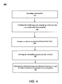
- FIG. 4 is a flowchart of a method for assembling a hard disk drive with deformable pogo pins and via holes in accordance with one embodiment of the present invention.
- Embodiments of the present invention are directed to a disk drive including deformable pogo pins attached to a preamplifier and via holes in a PCBA for connecting the PCBA to the preamplifier.
- Embodiments of the present invention are also directed to a disk drive including an extended flexible printed cable and a zero insertion force connector used to connect the PCBA to the preamplifier. With embodiments of the present invention, stress on the PCBA is reduced and the reliability of the HDD is improved.
- FIG. 1 a schematic drawing of one embodiment of an information storage system including a magnetic hard disk file or HDD 110 for a computer system is shown, although only one head and one disk surface combination are shown. What is described herein for one head-disk combination is also applicable to multiple head-disk combinations. In other words, the present technology is independent of the number of head-disk combinations.
- HDD 110 has an outer housing 113 usually including a base portion (shown) and a top or cover (not shown).
- housing 113 contains a disk pack having at least one media or magnetic disk 138 .
- the disk pack (as represented by disk 138 ) defines an axis of rotation and a radial direction relative to the axis in which the disk pack is rotatable.
- a spindle motor assembly having a central drive hub 130 operates as the axis and rotates the disk 138 or disks of the disk pack in the radial direction relative to housing 113 .
- An actuator assembly 140 includes one or more actuator arms 145 . When a number of actuator arms 145 are present, they are usually represented in the form of a comb that is movably or pivotally mounted to base/housing 113 .
- a controller 150 is also mounted to base 113 for selectively moving the actuator arms 145 relative to the disk 138 .
- Actuator assembly 140 may be coupled with a connector assembly, such as a flex cable to convey data between arm electronics and a host system, such as a computer, wherein HDD 110 resides.
- each actuator arm 145 has extending from it at least one cantilevered integrated lead suspension (ILS) 120 .
- the ILS 120 may be any form of lead suspension that can be used in a data access storage device.
- the level of integration containing the slider 121 , ILS 120 , and read/write head is called the head stack assembly.
- the ILS 120 has a spring-like quality, which biases or presses the air-bearing surface of slider 121 against disk 138 to cause slider 121 to fly at a precise distance from disk 138 .
- ILS 120 has a hinge area that provides for the spring-like quality, and a flexing cable-type interconnect that supports read and write traces and electrical connections through the hinge area.
- a voice coil 112 free to move within a conventional voice coil motor magnet assembly is also mounted to actuator arms 145 opposite the head stack assemblies. Movement of the actuator assembly 140 causes the head stack assembly to move along radial arcs across tracks on the surface of disk 138 .
- FIG. 2 is an exemplary diagram of a hard disk 110 using deformable pogo pins (hereinafter “DPP”) and via holes to connect the PCBA to the preamplifier.
- hard disk 110 is shown to include, in part, DPP 210 which is attached to preamplifier 250 and inserted into vial hole 230 which is part of PCBA 240 .
- DPP 220 is also shown as one alternative of a DPP which can be used in embodiments of the present technology.
- hard disk 110 comprises DPP 210 which is shown to have an enlarged tip, the enlarged tip having a sharp edge around the widest diameter, and a portion of the DPP is hollow.
- hollow portion of DPP 210 can be formed in multiple ways.
- DPP 210 has a hollow portion which is formed by a hole or a series of holes formed where the axis of the length of such holes or hole is perpendicular to the axis of the length of the DPP.
- DPP has a hollow portion formed in such a way that it is contained entirely in the interior of the DPP and cannot be seen from the exterior of the DPP.
- hard disk 110 may be comprised of DPP similar to DPP 220 which has an enlarged tip, the enlarged tip having rounded edges, and a slot formed starting at the tip and moving part way down the DPP.
- DPP similar to DPP 220 which has an enlarged tip, the enlarged tip having rounded edges, and a slot formed starting at the tip and moving part way down the DPP.
- Forming the DPP with an enlarged tip ensures that good contact will be made between the DPP and via hole 230 .
- an enlarged tip allows pressure to be placed on the DPP in such a way that will allow the DPP to deform as it is inserted into the via hole. Such deformation also ensures that good contact will be made at more than one point for each DPP and via hole.
- embodiments of the present technology are not limited to DPP 210 and DPP 220 .
- aspects of DPP 210 and DPP 220 may be combined in various embodiments.
- a DPP can have the rounded edges of DPP 220 and the hollow portion of DPP 210 .
- various embodiments of the present technology use more than one DPP and are not limited to using one type of DPP.
- via hole 230 is formed in PCBA 240 . It should be appreciated that via hole 230 and the DPP are formed in such a way that will allow the DPP to be deformed upon insertion into via hole 230 . In one embodiment, this is accomplished by forming via hole 230 with a diameter which is smaller than the diameter of the DPP. This ensures that the DPP will deform to match the diameter of via hole 230 upon insertion. In one embodiment, via hole 230 is formed using material that harder is substance than the DPP. The harder substance of the material of via hole 230 will ensure that the DPP is deformed upon insertion. In one embodiment, the via hole deforms instead of the DPP.
- the DPP is inserted into via hole 230 as PCBA 240 is connected to the housing of hard disk 110 .
- the DPP does not result in a force which opposes the forces which connect PCBA 240 to the housing of hard disk 110 .
- PCBA 240 is typically connected to the housing of hard disk 110 using screws which apply a force perpendicular to the planar surface of PCBA 240 which force is directly opposed by pogo pins.
- the force resulting from the DPP being inserted into the via holes is parallel to the planar surface of PCBA 240 . Therefore the stress on PCBA 240 is relieved and the reliability of the HDD is improved.
- fewer screws can be used to connect PCBA 240 to the housing of hard disk 110 because there is less force resisting the connection; this saves costs in screws and in assembly time.
- FIG. 3 is an exemplary diagram of a hard disk 110 using zero insertion force connector 340 (hereinafter “ZIFC 340 ”) and extended flexible printed cable 330 (hereinafter “EFPC 330 ”) to connect PCBA 350 to preamplifier 310 .
- hard disk 110 is shown to include, in part, EFPC 330 which is attached to preamplifier 310 and inserted into ZIFC 340 which is part of PCBA 350 .
- ZIFC 340 is a zero insertion force connector commonly used in the industry. In one embodiment, ZIFC 340 is connected to EFPC 330 . In such an embodiment, the connection does not result in a force that would tend to push PCBA 350 away from preamplifier 310 . This avoids stress on PCBA 350 and can be more efficient in assembly.
- FIG. 4 is a flowchart of a method 400 for assembling a hard disk drive in accordance with one embodiment of the present invention.
- 400 includes providing a preamplifier.
- 400 includes providing deformable pogo pins comprising a shaft and a tip and coupled with the preamplifier.
- 400 includes forming via holes in a printed circuit board assembly.
- 400 includes inserting the deformable pogo pins into the via holes.
- 400 includes deforming the deformable pogo pins during the inserting to couple the printed circuit board assembly to the preamplifier.
- embodiments of the present invention provide a method and apparatus for connecting a preamplifier to a printed circuit board assembly on a hard disk drive.
Abstract
Description
Claims (16)
Priority Applications (1)
| Application Number | Priority Date | Filing Date | Title |
|---|---|---|---|
| US12/324,813 US8098459B2 (en) | 2008-11-26 | 2008-11-26 | Connecting a preamplifier to a printed circuit board assembly on a hard disk drive |
Applications Claiming Priority (1)
| Application Number | Priority Date | Filing Date | Title |
|---|---|---|---|
| US12/324,813 US8098459B2 (en) | 2008-11-26 | 2008-11-26 | Connecting a preamplifier to a printed circuit board assembly on a hard disk drive |
Publications (2)
| Publication Number | Publication Date |
|---|---|
| US20100128398A1 US20100128398A1 (en) | 2010-05-27 |
| US8098459B2 true US8098459B2 (en) | 2012-01-17 |
Family
ID=42196030
Family Applications (1)
| Application Number | Title | Priority Date | Filing Date |
|---|---|---|---|
| US12/324,813 Expired - Fee Related US8098459B2 (en) | 2008-11-26 | 2008-11-26 | Connecting a preamplifier to a printed circuit board assembly on a hard disk drive |
Country Status (1)
| Country | Link |
|---|---|
| US (1) | US8098459B2 (en) |
Citations (26)
| Publication number | Priority date | Publication date | Assignee | Title |
|---|---|---|---|---|
| EP0710955A2 (en) | 1994-11-02 | 1996-05-08 | Hitachi, Ltd. | Data storage apparatus |
| JPH08212728A (en) | 1994-12-06 | 1996-08-20 | Fujitsu Ltd | Disk device |
| JPH103758A (en) | 1996-06-14 | 1998-01-06 | Fujitsu Ltd | Disk device |
| EP0825680A2 (en) | 1996-08-23 | 1998-02-25 | CTS Corporation | Deformable pin electrical connector |
| US5760997A (en) | 1994-09-29 | 1998-06-02 | International Business Machines Corporation | Flexible cable structure for magnetic disk drives |
| US5844754A (en) | 1993-11-12 | 1998-12-01 | Seagate Technology, Inc. | Stackable actuator assembly having spring retaining system |
| US5910862A (en) | 1993-12-07 | 1999-06-08 | Fujitsu Limited | Magnetic disk apparatus |
| US5953183A (en) * | 1997-11-17 | 1999-09-14 | Western Digital Corporation | Head stack assembly for a magnetic disk drive with a pass-through flex circuit cable |
| US6057982A (en) | 1997-03-31 | 2000-05-02 | Seagate Technology, Inc. | Disc drive head disc assembly and printed circuit board connected with flexible connectors |
| JP2000243076A (en) | 1999-02-12 | 2000-09-08 | Internatl Business Mach Corp <Ibm> | Method for joining flex cable and circuit board of hard disk device and hard disk device utilizing the same |
| US6178056B1 (en) | 1997-03-11 | 2001-01-23 | Western Digital Corporation | Disk drive employing state variable trap registers for providing stored servo and user data state variables to sampled-data channel |
| US6270375B1 (en) | 1998-06-15 | 2001-08-07 | Seagate Technology Llc | Low inductance flex-to-PCB spring connector for a disc drive |
| US20020006005A1 (en) | 1998-11-02 | 2002-01-17 | Kazuyoshi Akutsu | A storage device having head ic configuration processing |
| US6351343B1 (en) | 1994-10-28 | 2002-02-26 | International Business Machines Corporation | Arrangement structure of the printed circuit board and the interface cable connector of a magnetic disk drive |
| US6452754B1 (en) | 1998-06-08 | 2002-09-17 | Alps Electric Co., Ltd. | Flexible printed circuit board attachment structure and recording and reproducing device using the same |
| US6472866B2 (en) * | 2000-02-17 | 2002-10-29 | Seagate Technologies Llc | Head stack assembly (HSA) with shunt testing access port |
| US20030022533A1 (en) | 2001-06-16 | 2003-01-30 | Sung-Hyuk Joo | Signal transmission connector in a computer hard disk drive |
| US20030142243A1 (en) | 1996-06-14 | 2003-07-31 | Bong-Jin Lee | Hard disk drive with connectors that simplify assembly |
| US6631052B1 (en) * | 1999-01-13 | 2003-10-07 | Applied Kinetics, Inc. | Head interconnect with support material carbonized shunt |
| US6702592B1 (en) * | 1999-12-03 | 2004-03-09 | Seagate Technology Llc | Printed circuit board assembly with secondary side rigid electrical pin to mate with compliant contact |
| US6809905B2 (en) * | 2001-11-27 | 2004-10-26 | Kla-Tencor Technologies Corporation | Electrical interconnect scheme |
| US20060141816A1 (en) | 2004-12-27 | 2006-06-29 | Hitachi Global Storage Technologies Netherlands B.V. | FPC-connector connecting structure and magnetic disk |
| US20060180346A1 (en) | 2005-02-17 | 2006-08-17 | Suzanne Knight | High aspect ratio plated through holes in a printed circuit board |
| JP2007207300A (en) | 2006-01-31 | 2007-08-16 | Toshiba Corp | Disk drive |
| US7291795B2 (en) * | 2004-04-01 | 2007-11-06 | Arie Maharshak | Flexible printed circuits with many tiny holes |
| US7377823B2 (en) | 2005-05-23 | 2008-05-27 | J.S.T. Corporation | Press-fit pin |
-
2008
- 2008-11-26 US US12/324,813 patent/US8098459B2/en not_active Expired - Fee Related
Patent Citations (27)
| Publication number | Priority date | Publication date | Assignee | Title |
|---|---|---|---|---|
| US5844754A (en) | 1993-11-12 | 1998-12-01 | Seagate Technology, Inc. | Stackable actuator assembly having spring retaining system |
| US5910862A (en) | 1993-12-07 | 1999-06-08 | Fujitsu Limited | Magnetic disk apparatus |
| US5760997A (en) | 1994-09-29 | 1998-06-02 | International Business Machines Corporation | Flexible cable structure for magnetic disk drives |
| US6351343B1 (en) | 1994-10-28 | 2002-02-26 | International Business Machines Corporation | Arrangement structure of the printed circuit board and the interface cable connector of a magnetic disk drive |
| EP0710955A2 (en) | 1994-11-02 | 1996-05-08 | Hitachi, Ltd. | Data storage apparatus |
| JPH08212728A (en) | 1994-12-06 | 1996-08-20 | Fujitsu Ltd | Disk device |
| US6875026B2 (en) | 1996-06-14 | 2005-04-05 | Samsung Electronics Co., Ltd | Hard disk drive with connectors that simplify assembly |
| US20030142243A1 (en) | 1996-06-14 | 2003-07-31 | Bong-Jin Lee | Hard disk drive with connectors that simplify assembly |
| JPH103758A (en) | 1996-06-14 | 1998-01-06 | Fujitsu Ltd | Disk device |
| EP0825680A2 (en) | 1996-08-23 | 1998-02-25 | CTS Corporation | Deformable pin electrical connector |
| US6178056B1 (en) | 1997-03-11 | 2001-01-23 | Western Digital Corporation | Disk drive employing state variable trap registers for providing stored servo and user data state variables to sampled-data channel |
| US6057982A (en) | 1997-03-31 | 2000-05-02 | Seagate Technology, Inc. | Disc drive head disc assembly and printed circuit board connected with flexible connectors |
| US5953183A (en) * | 1997-11-17 | 1999-09-14 | Western Digital Corporation | Head stack assembly for a magnetic disk drive with a pass-through flex circuit cable |
| US6452754B1 (en) | 1998-06-08 | 2002-09-17 | Alps Electric Co., Ltd. | Flexible printed circuit board attachment structure and recording and reproducing device using the same |
| US6270375B1 (en) | 1998-06-15 | 2001-08-07 | Seagate Technology Llc | Low inductance flex-to-PCB spring connector for a disc drive |
| US20020006005A1 (en) | 1998-11-02 | 2002-01-17 | Kazuyoshi Akutsu | A storage device having head ic configuration processing |
| US6631052B1 (en) * | 1999-01-13 | 2003-10-07 | Applied Kinetics, Inc. | Head interconnect with support material carbonized shunt |
| JP2000243076A (en) | 1999-02-12 | 2000-09-08 | Internatl Business Mach Corp <Ibm> | Method for joining flex cable and circuit board of hard disk device and hard disk device utilizing the same |
| US6702592B1 (en) * | 1999-12-03 | 2004-03-09 | Seagate Technology Llc | Printed circuit board assembly with secondary side rigid electrical pin to mate with compliant contact |
| US6472866B2 (en) * | 2000-02-17 | 2002-10-29 | Seagate Technologies Llc | Head stack assembly (HSA) with shunt testing access port |
| US20030022533A1 (en) | 2001-06-16 | 2003-01-30 | Sung-Hyuk Joo | Signal transmission connector in a computer hard disk drive |
| US6809905B2 (en) * | 2001-11-27 | 2004-10-26 | Kla-Tencor Technologies Corporation | Electrical interconnect scheme |
| US7291795B2 (en) * | 2004-04-01 | 2007-11-06 | Arie Maharshak | Flexible printed circuits with many tiny holes |
| US20060141816A1 (en) | 2004-12-27 | 2006-06-29 | Hitachi Global Storage Technologies Netherlands B.V. | FPC-connector connecting structure and magnetic disk |
| US20060180346A1 (en) | 2005-02-17 | 2006-08-17 | Suzanne Knight | High aspect ratio plated through holes in a printed circuit board |
| US7377823B2 (en) | 2005-05-23 | 2008-05-27 | J.S.T. Corporation | Press-fit pin |
| JP2007207300A (en) | 2006-01-31 | 2007-08-16 | Toshiba Corp | Disk drive |
Non-Patent Citations (1)
| Title |
|---|
| Jawaid, Shams et al., "Design Evaluation & Product Reliability Assessment Using Accelerated Reliability Fatigue Life Tests", Reliability abd Maintainability Symposium http://ieeexplore.ieee.org/appliation/mdl/mdlconfirmation.jsp?arnumber=816314, (2000),239-244. |
Also Published As
| Publication number | Publication date |
|---|---|
| US20100128398A1 (en) | 2010-05-27 |
Similar Documents
| Publication | Publication Date | Title |
|---|---|---|
| US8064168B1 (en) | Head stack assembly with flexure tail retention features | |
| US7315435B1 (en) | Disk drives, head stack, head gimbal and suspension assemblies having positional conductive features | |
| US8068314B1 (en) | Head stack assembly with suspension tails extending into interfering slits in a flexible printed circuit | |
| US8284514B1 (en) | Disk drive having a clamp fastener with a convex head | |
| US9218833B1 (en) | Load/unload ramps for multiple disk-stack, shared actuator hard disk drive | |
| US7907369B1 (en) | Head gimbal assembly with flexure tail having bent alignment tab feature | |
| US7672083B1 (en) | Disk drive with translatable ramp | |
| US8379363B1 (en) | Bulk erase tool to erase a perpendicular media recording disk of a disk drive | |
| US20060227517A1 (en) | Modified connector for improved manufacturing and testing | |
| US8024853B2 (en) | Head gimbal assembly (HGA) connector pad alignment jig | |
| US20060152856A1 (en) | Short-tail head gimbal assembly testing fixture | |
| US20070076317A1 (en) | Servowriter ramp detection | |
| US6721135B2 (en) | Printed circuit cable connector attachment assembly | |
| JP3080362B2 (en) | Crash stop and disk device using the same | |
| US20230352048A1 (en) | Hard disk drive multiple contact disk clamp | |
| US20230352047A1 (en) | Hard disk drive multiple contact disk spindle motor hub flange | |
| US9361932B2 (en) | Fluid dynamic bearing groove configuration | |
| US20160365105A1 (en) | Hard Disk Drive Actuator Pivot To Base Tower Clearance Spacer Mechanism | |
| US8098459B2 (en) | Connecting a preamplifier to a printed circuit board assembly on a hard disk drive | |
| US9343101B2 (en) | Hard disk drive low profile disk clamp to tied-shaft motor assembly | |
| US11430474B1 (en) | Hard disk drive suspension tail having narrowing tip | |
| US11227630B2 (en) | Swage plate assembly with swage boss insert | |
| US8520341B2 (en) | Reducing gram load change in actuator arm in a hard disk drive | |
| US7352532B2 (en) | Method and apparatus for utilizing a small pad to increase a head to a disk interface reliability for a load/unload drive | |
| US11232811B2 (en) | Offset swage baseplate for stacked assembly |
Legal Events
| Date | Code | Title | Description |
|---|---|---|---|
| AS | Assignment |
Owner name: HITACHI GLOBAL STORAGE TECHNOLOGIES NETHERLANDS B. Free format text: ASSIGNMENT OF ASSIGNORS INTEREST;ASSIGNORS:CHAN, YEOW YONG;JIANG, HONGYAN;LIU, SHAOYONG;AND OTHERS;REEL/FRAME:022077/0952 Effective date: 20081122 |
|
| FEPP | Fee payment procedure |
Free format text: PAYOR NUMBER ASSIGNED (ORIGINAL EVENT CODE: ASPN); ENTITY STATUS OF PATENT OWNER: LARGE ENTITY |
|
| STCF | Information on status: patent grant |
Free format text: PATENTED CASE |
|
| CC | Certificate of correction | ||
| CC | Certificate of correction | ||
| AS | Assignment |
Owner name: HGST, NETHERLANDS B.V., NETHERLANDS Free format text: CHANGE OF NAME;ASSIGNOR:HGST, NETHERLANDS B.V.;REEL/FRAME:029341/0777 Effective date: 20120723 Owner name: HGST NETHERLANDS B.V., NETHERLANDS Free format text: CHANGE OF NAME;ASSIGNOR:HITACHI GLOBAL STORAGE TECHNOLOGIES NETHERLANDS B.V.;REEL/FRAME:029341/0777 Effective date: 20120723 |
|
| FPAY | Fee payment |
Year of fee payment: 4 |
|
| AS | Assignment |
Owner name: WESTERN DIGITAL TECHNOLOGIES, INC., CALIFORNIA Free format text: ASSIGNMENT OF ASSIGNORS INTEREST;ASSIGNOR:HGST NETHERLANDS B.V.;REEL/FRAME:040826/0821 Effective date: 20160831 |
|
| FEPP | Fee payment procedure |
Free format text: MAINTENANCE FEE REMINDER MAILED (ORIGINAL EVENT CODE: REM.); ENTITY STATUS OF PATENT OWNER: LARGE ENTITY |
|
| LAPS | Lapse for failure to pay maintenance fees |
Free format text: PATENT EXPIRED FOR FAILURE TO PAY MAINTENANCE FEES (ORIGINAL EVENT CODE: EXP.); ENTITY STATUS OF PATENT OWNER: LARGE ENTITY |
|
| STCH | Information on status: patent discontinuation |
Free format text: PATENT EXPIRED DUE TO NONPAYMENT OF MAINTENANCE FEES UNDER 37 CFR 1.362 |
|
| FP | Lapsed due to failure to pay maintenance fee |
Effective date: 20200117 |