US8092945B2 - Fuel cell system - Google Patents
Fuel cell system Download PDFInfo
- Publication number
- US8092945B2 US8092945B2 US11/629,456 US62945605A US8092945B2 US 8092945 B2 US8092945 B2 US 8092945B2 US 62945605 A US62945605 A US 62945605A US 8092945 B2 US8092945 B2 US 8092945B2
- Authority
- US
- United States
- Prior art keywords
- fuel cell
- ions
- cell system
- inflow line
- ion
- Prior art date
- Legal status (The legal status is an assumption and is not a legal conclusion. Google has not performed a legal analysis and makes no representation as to the accuracy of the status listed.)
- Expired - Fee Related, expires
Links
- 239000000446 fuel Substances 0.000 title claims abstract description 178
- 150000002500 ions Chemical class 0.000 claims abstract description 293
- MHAJPDPJQMAIIY-UHFFFAOYSA-N Hydrogen peroxide Chemical compound OO MHAJPDPJQMAIIY-UHFFFAOYSA-N 0.000 claims abstract description 120
- 239000003792 electrolyte Substances 0.000 claims abstract description 54
- 239000002904 solvent Substances 0.000 claims description 71
- 150000001875 compounds Chemical class 0.000 claims description 52
- 239000007788 liquid Substances 0.000 claims description 50
- 239000000126 substance Substances 0.000 claims description 30
- 238000010828 elution Methods 0.000 claims description 29
- 239000000463 material Substances 0.000 claims description 26
- UFHFLCQGNIYNRP-UHFFFAOYSA-N Hydrogen Chemical compound [H][H] UFHFLCQGNIYNRP-UHFFFAOYSA-N 0.000 claims description 12
- 229910052739 hydrogen Inorganic materials 0.000 claims description 12
- 239000001257 hydrogen Substances 0.000 claims description 12
- 230000002378 acidificating effect Effects 0.000 claims description 7
- 229910044991 metal oxide Inorganic materials 0.000 claims description 7
- 150000004706 metal oxides Chemical class 0.000 claims description 7
- QVGXLLKOCUKJST-UHFFFAOYSA-N atomic oxygen Chemical compound [O] QVGXLLKOCUKJST-UHFFFAOYSA-N 0.000 claims description 6
- 229910052760 oxygen Inorganic materials 0.000 claims description 6
- 239000001301 oxygen Substances 0.000 claims description 6
- 230000001737 promoting effect Effects 0.000 claims description 4
- 239000011248 coating agent Substances 0.000 description 40
- 238000000576 coating method Methods 0.000 description 40
- 239000012495 reaction gas Substances 0.000 description 39
- 239000012528 membrane Substances 0.000 description 33
- 239000010410 layer Substances 0.000 description 25
- 230000002000 scavenging effect Effects 0.000 description 22
- 239000002253 acid Substances 0.000 description 21
- 239000011247 coating layer Substances 0.000 description 18
- 230000006866 deterioration Effects 0.000 description 18
- 238000010586 diagram Methods 0.000 description 14
- 239000003054 catalyst Substances 0.000 description 12
- 238000009792 diffusion process Methods 0.000 description 9
- 235000012209 glucono delta-lactone Nutrition 0.000 description 9
- QAOWNCQODCNURD-UHFFFAOYSA-N Sulfuric acid Chemical compound OS(O)(=O)=O QAOWNCQODCNURD-UHFFFAOYSA-N 0.000 description 8
- 239000005518 polymer electrolyte Substances 0.000 description 7
- OKKJLVBELUTLKV-UHFFFAOYSA-N Methanol Chemical compound OC OKKJLVBELUTLKV-UHFFFAOYSA-N 0.000 description 6
- 238000010248 power generation Methods 0.000 description 6
- 238000011144 upstream manufacturing Methods 0.000 description 6
- 230000000052 comparative effect Effects 0.000 description 5
- 239000007789 gas Substances 0.000 description 5
- 238000010629 Molecular evolutionary genetics analysis Methods 0.000 description 4
- CETPSERCERDGAM-UHFFFAOYSA-N ceric oxide Chemical compound O=[Ce]=O CETPSERCERDGAM-UHFFFAOYSA-N 0.000 description 4
- 229910000422 cerium(IV) oxide Inorganic materials 0.000 description 4
- 238000005516 engineering process Methods 0.000 description 4
- XLYOFNOQVPJJNP-UHFFFAOYSA-N water Substances O XLYOFNOQVPJJNP-UHFFFAOYSA-N 0.000 description 4
- 238000006243 chemical reaction Methods 0.000 description 3
- 239000002826 coolant Substances 0.000 description 3
- 238000000034 method Methods 0.000 description 3
- 238000006722 reduction reaction Methods 0.000 description 3
- 239000011347 resin Substances 0.000 description 3
- 229920005989 resin Polymers 0.000 description 3
- YCKRFDGAMUMZLT-UHFFFAOYSA-N Fluorine atom Chemical compound [F] YCKRFDGAMUMZLT-UHFFFAOYSA-N 0.000 description 2
- 239000012156 elution solvent Substances 0.000 description 2
- 229910052731 fluorine Inorganic materials 0.000 description 2
- 239000011737 fluorine Substances 0.000 description 2
- 229910052684 Cerium Inorganic materials 0.000 description 1
- 229910001069 Ti alloy Inorganic materials 0.000 description 1
- 229910052782 aluminium Inorganic materials 0.000 description 1
- 239000006227 byproduct Substances 0.000 description 1
- 229910052799 carbon Inorganic materials 0.000 description 1
- 229920002678 cellulose Polymers 0.000 description 1
- 239000001913 cellulose Substances 0.000 description 1
- 229910052804 chromium Inorganic materials 0.000 description 1
- 239000004020 conductor Substances 0.000 description 1
- 238000001816 cooling Methods 0.000 description 1
- 238000005260 corrosion Methods 0.000 description 1
- 230000000694 effects Effects 0.000 description 1
- 238000003487 electrochemical reaction Methods 0.000 description 1
- 229910052737 gold Inorganic materials 0.000 description 1
- 229910052735 hafnium Inorganic materials 0.000 description 1
- 150000002431 hydrogen Chemical class 0.000 description 1
- 229910052741 iridium Inorganic materials 0.000 description 1
- 229910052742 iron Inorganic materials 0.000 description 1
- 238000012423 maintenance Methods 0.000 description 1
- 229910052748 manganese Inorganic materials 0.000 description 1
- 229910052751 metal Inorganic materials 0.000 description 1
- 239000002184 metal Substances 0.000 description 1
- 229910052759 nickel Inorganic materials 0.000 description 1
- 229910052758 niobium Inorganic materials 0.000 description 1
- 229910052763 palladium Inorganic materials 0.000 description 1
- 229910052697 platinum Inorganic materials 0.000 description 1
- 229910052761 rare earth metal Inorganic materials 0.000 description 1
- -1 rare-earth metal ions Chemical class 0.000 description 1
- 229910052703 rhodium Inorganic materials 0.000 description 1
- 229910052709 silver Inorganic materials 0.000 description 1
- 239000007787 solid Substances 0.000 description 1
- 229910052715 tantalum Inorganic materials 0.000 description 1
- 229910052718 tin Inorganic materials 0.000 description 1
- 229910052719 titanium Inorganic materials 0.000 description 1
- 239000010936 titanium Substances 0.000 description 1
- 229910001428 transition metal ion Inorganic materials 0.000 description 1
- 229910052726 zirconium Inorganic materials 0.000 description 1
Images


Classifications
-
- H—ELECTRICITY
- H01—ELECTRIC ELEMENTS
- H01M—PROCESSES OR MEANS, e.g. BATTERIES, FOR THE DIRECT CONVERSION OF CHEMICAL ENERGY INTO ELECTRICAL ENERGY
- H01M8/00—Fuel cells; Manufacture thereof
- H01M8/04—Auxiliary arrangements, e.g. for control of pressure or for circulation of fluids
- H01M8/04082—Arrangements for control of reactant parameters, e.g. pressure or concentration
-
- H—ELECTRICITY
- H01—ELECTRIC ELEMENTS
- H01M—PROCESSES OR MEANS, e.g. BATTERIES, FOR THE DIRECT CONVERSION OF CHEMICAL ENERGY INTO ELECTRICAL ENERGY
- H01M4/00—Electrodes
- H01M4/86—Inert electrodes with catalytic activity, e.g. for fuel cells
- H01M4/8605—Porous electrodes
-
- H—ELECTRICITY
- H01—ELECTRIC ELEMENTS
- H01M—PROCESSES OR MEANS, e.g. BATTERIES, FOR THE DIRECT CONVERSION OF CHEMICAL ENERGY INTO ELECTRICAL ENERGY
- H01M4/00—Electrodes
- H01M4/86—Inert electrodes with catalytic activity, e.g. for fuel cells
- H01M4/90—Selection of catalytic material
- H01M4/9016—Oxides, hydroxides or oxygenated metallic salts
-
- H—ELECTRICITY
- H01—ELECTRIC ELEMENTS
- H01M—PROCESSES OR MEANS, e.g. BATTERIES, FOR THE DIRECT CONVERSION OF CHEMICAL ENERGY INTO ELECTRICAL ENERGY
- H01M8/00—Fuel cells; Manufacture thereof
- H01M8/06—Combination of fuel cells with means for production of reactants or for treatment of residues
- H01M8/0662—Treatment of gaseous reactants or gaseous residues, e.g. cleaning
-
- H—ELECTRICITY
- H01—ELECTRIC ELEMENTS
- H01M—PROCESSES OR MEANS, e.g. BATTERIES, FOR THE DIRECT CONVERSION OF CHEMICAL ENERGY INTO ELECTRICAL ENERGY
- H01M8/00—Fuel cells; Manufacture thereof
- H01M8/10—Fuel cells with solid electrolytes
- H01M8/1004—Fuel cells with solid electrolytes characterised by membrane-electrode assemblies [MEA]
-
- H—ELECTRICITY
- H01—ELECTRIC ELEMENTS
- H01M—PROCESSES OR MEANS, e.g. BATTERIES, FOR THE DIRECT CONVERSION OF CHEMICAL ENERGY INTO ELECTRICAL ENERGY
- H01M4/00—Electrodes
- H01M4/86—Inert electrodes with catalytic activity, e.g. for fuel cells
- H01M4/90—Selection of catalytic material
- H01M4/92—Metals of platinum group
-
- Y—GENERAL TAGGING OF NEW TECHNOLOGICAL DEVELOPMENTS; GENERAL TAGGING OF CROSS-SECTIONAL TECHNOLOGIES SPANNING OVER SEVERAL SECTIONS OF THE IPC; TECHNICAL SUBJECTS COVERED BY FORMER USPC CROSS-REFERENCE ART COLLECTIONS [XRACs] AND DIGESTS
- Y02—TECHNOLOGIES OR APPLICATIONS FOR MITIGATION OR ADAPTATION AGAINST CLIMATE CHANGE
- Y02E—REDUCTION OF GREENHOUSE GAS [GHG] EMISSIONS, RELATED TO ENERGY GENERATION, TRANSMISSION OR DISTRIBUTION
- Y02E60/00—Enabling technologies; Technologies with a potential or indirect contribution to GHG emissions mitigation
- Y02E60/30—Hydrogen technology
- Y02E60/50—Fuel cells
Definitions
- the invention relates to a fuel cell system, and more particularly to a fuel cell system including a fuel cell having improved durability.
- the MEA includes an electrolyte and electrodes (a cathode and an anode). One of the electrodes is provided on one side of the electrolyte, and the other of the electrodes is provided on the other side of the electrolyte.
- the electric energy generated is taken out of the MEA via separators. A separator is provided on one side of the MEA, and another separator is provided on the other side of the MEA.
- a polymer electrolyte fuel cell (hereinafter, referred to as “PEFC”), which is one type of fuel cell, is used in a co-generation system for home use, an automobile, and the like.
- the PEFC can operate at low temperatures. Generally, the PEFC operates between temperatures of 50 to 100° C.
- the PEFC has a high energy-conversion efficiency of 50 to 60%. It takes only a short time to start the operation of the PEFC. Also, PEFC systems are compact and light. Therefore, the PEFC is suitable for use as a power source for an electric vehicle, a portable power source, and the like.
- An individual PEFC cell includes an electrolyte membrane, a cathode, an anode, and separators. Each of the cathode and the anode includes a catalyst layer and a diffusion layer.
- a single PEFC cell has a theoretical electromotive force of 1.23 volts. Because an individual cell has such a low electromotive force, it cannot supply sufficient power to move an electric vehicle and the like. Therefore, ordinarily, a fuel cell stack is used.
- a fuel cell stack includes a stack body, end plates, and the like. The stack body is formed by stacking individual cells in series. The end plates are disposed at both ends of the stack body in the direction in which the individual cells are stacked.
- JP 2003-100308 A discloses an example of a technology for improving the electric power generation performance of a fuel cell. More specifically, JP 2003-100308 A discloses a cathode catalyst for a fuel cell. In the cathode catalyst, a carrier that supports Pt further supports CeO 2 . By using this catalyst, the reduction reaction of oxygen proceeds at an increased rate. Also, Japanese Patent Application Publication No. JP 2003-86192 A (hereinafter “JP 2003-86192 A”) discloses a fuel cell in which a cathode electrode includes a catalyst/oxide/polymer electrolyte thin layer.
- the catalyst/oxide/polymer electrolyte thin layer is made of an oxide, a catalyst, and a solid polymer electrolyte material.
- cross over is suppressed.
- the reduction of the electric power generation performance due to the cross over can be prevented.
- a first aspect of the invention relates to a fuel cell system including a stack body and supply means/portion.
- the stack body is formed by stacking a membrane-electrode assembly (hereinafter, referred to as “MEA”) and a separator.
- MEA membrane-electrode assembly
- the MEA includes an electrolyte layer and electrode layers, one of which is provided on one side of the electrolyte layer and the other of which is provided on the other side of the electrolyte layer.
- the supply means/portion supplies ions that can scavenge hydrogen peroxide in the MEA.
- hydrogen peroxide scavinging ions can be supplied into the MEA from the outside of the MEA. Therefore, the MEA is constantly supplied with the ions while the fuel cell generates electric power. That is, according to the first aspect of the invention, the deterioration of the electrolyte caused by hydrogen peroxide can be suppressed by scaveneging the hydrogen peroxide in the MEA using ions that can scavenge hydrogen peroxide.
- a substance to be supplied to the membrane-electrode assembly may carry the ions to the MEA.
- the supply means/portion may include an inflow line for supplying the substance to be supplied to the membrane-electrode assembly; and ion adding means/portion for adding the ions to the substance to be supplied to the membrane-electrode assembly.
- the ion adding means/portion may be provided in either the inflow line or the separator.
- the ion adding means/portion that is provided in either the inflow line or the separator can add the hydrogen peroxide scavenging ions to the substance to be supplied to the MEA before the substance reaches the MEA.
- the hydrogen peroxide scavenging ions can be easily supplied to the MEA.
- the ion adding means/portion may include at least one of an element and a compound from which the hydrogen peroxide scaveneging ions are eluted; and ion elution promotion means/portion for promoting elution of the ions from the at least one of the element and the compound.
- the ion adding means/portion includes the ion elution promotion means/portion for promoting the elution of the ions which have the ability to scavenge hydrogen peroxide from at least one of the element and the compound, the ions can be added to the substance to be supplied to the MEA more effectively.
- the hydrogen peroxide scavenging ions can be supplied to the MEA more easily.
- the ion elution promotion means/portion may be an elution solvent adding means/portion for adding elution solvent that elutes hydrogen peroxide scavenging ions.
- the hydrogen peroxide scavenging ions are eluted using the eluting solvent, the ions can be eluted at desired timing in the fuel cell system.
- At least one of the element and the compound from which the ions having the ability to scavenge hydrogen peroxide are eluted may be replaceable.
- either or both the element or the compound from which the ions having the ability to scavenge hydrogen peroxide are eluted is provided, and either or both of the element and the compound is replaceable. Therefore, a small amount of the at least one of the element and the compound can be added at a time. This prevents the reduction of the electric power generation performance caused by adding a great amount of the at least one of the element and the compound. Thus, the durability of the fuel cell can be improved in the fuel cell system without reducing the electric power generation performance for a long period.
- the at least one of the element and the compound from which the hydrogen peroxide scavenging ions may be provided in a portion of the pipe extending in a horizontal direction, which includes at least a lower portion of the pipe in a direction of gravitational force.
- the amount of the at least one of the element and the compound per unit area of the portion of the pipe may be greater than the amount of the at least one of the element and the compound per unit area of any other portion of the pipe.
- the substance that promotes elution of the ions which can scavenge hydrogen peroxide is likely accumulate in the low portion in the direction of gravitational force.
- a greater amount of the at least one of the element and the compound from which the ions having the ability to scavenge hydrogen peroxide are eluted is provided in the low portion in the direction of gravitational force. Therefore, the ions having the ability to scavenge hydrogen peroxide can be effectively eluted.
- the durability of the fuel cell can be easily improved in the fuel cell system.
- the at least one of the element and the compound may be provided in a portion of the ion adding means/portion, which includes a lowermost portion of the ion adding means/portion in the direction of gravitational force.
- the at least one of the element and the compound may be provided in the ion adding means/portion such that the average mass of the at least one of the element and the compound per unit area of a lower half portion of the ion adding means/portion in the direction of gravitational force is greater than the average mass of the at least one of the element and the compound per unit area of an upper half portion of the ion adding means/portion in the direction of gravitational force.
- a hygroscopic material may be provided in at least a portion of the surface of the at least one of the element and the compound from which the hydrogen peroxide scavenging ions are eluted.
- the hydroscopic material is provided in at least a portion of the surface of the at least one of the element and the compound, the substance that promotes the elution of the ion can be efficiently supplied to the surface of the at least one of the element and the compound.
- the ions can be easily eluted.
- the ion adding means/portion may include the compound from which the hydrogen peroxide scavenging ions are eluted; and the eluting solvent adding means/portion.
- the compound may be a metal oxide, and the eluting solvent added by the eluting solvent adding means/portion may be an acidic solvent.
- the hydrogen peroxide scavenging ions are eluted from the metal oxide using the acidic eluting solvent, the ions can be easily eluted, and the durability of the fuel cell can be improved in the fuel cell system.
- the ion adding means/portion may include ion-containing liquid storage means/portion for storing liquid containing the hydrogen peroxide scavenging ions; and introduction means/portion for introducing the liquid in the ion-containing liquid storage means/portion to the at least one of the inflow line and the separator.
- the introduction means/portion may include control means/portion for controlling a mode in which the liquid containing the hydrogen peroxide scavenging ions is introduced into the either or both of the inflow line and the separator.
- the hydrogen peroxide in the MEA can be decomposed by the ions more effectively. Also, because the control means/portion is provided for controlling the mode in which the liquid containing the hydrogen peroxide scavenging ions is introduced, the amount of the liquid to be supplied to the MEA, timing at which the liquid can be supplied to the MEA, and the like can be controlled. Thus, the liquid containing the ions can be used without wasting the liquid in the fuel cell system.
- a key feature of the invention is to provide a fuel cell system in which the durability of the fuel cell can be improved by supplying hydrogen peroxide scavenging ions to the MEA.
- FIG. 1 is a schematic diagram showing a fuel cell system in a first embodiment of the invention
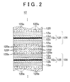
- FIG. 2 is a schematic sectional view showing an example of the configuration of the fuel cell stack
- FIGS. 3A and 3B are schematic diagrams each showing a fuel cell system in an exemplary embodiment of the invention.
- FIGS. 4A and 4B are schematic diagrams each showing an example of ion adding means/portion
- FIGS. 5A , 5 B, and 5 C are schematic diagrams each showing an example of ion adding means/portion
- FIG. 6 is a schematic diagram showing an example of ion adding means/portion
- FIG. 7 is a schematic diagram showing a fuel cell system in a fourth embodiment of the invention.
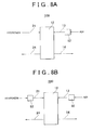
- FIGS. 8A and 8B are schematic diagrams each showing a fuel cell system in an exemplary embodiment of the invention.
- FIG. 9 is a schematic diagram showing an example of a separator including ion adding means/portion.
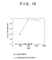
- FIG. 10 is a graph showing the result of a durability test.
- a PEFC is used.
- FIG. 1 is a schematic diagram showing a fuel cell system in a first embodiment of the invention.
- a fuel cell system 100 according to the first embodiment of the invention includes an anode inflow line 11 , a fuel cell stack (hereinafter, referred to as “FC stack”) 12 , a cathode inflow line 13 , and a cathode discharge line 14 .
- the anode inflow line 11 is a circulating system for circulating and supplying a substance containing hydrogen, which can include, but is not limited to diatomic hydrogen.
- the FC stack 12 includes a stack body (not shown) formed by stacking MEAs and separators.
- the cathode inflow line 13 is a non-circulating system for supplying a substance containing oxygen, which can include, but is not limited to atmospheric air.
- Ion adding means/portion 90 is provided in the anode inflow line 11 .
- the ion adding means/portion 90 according to this embodiment is a pipe that constitutes a portion of the anode inflow line 11 . More specifically, the ion adding means/portion 90 (hereinafter, may be referred to as “pipe 90 ”) constitutes an upstream portion of the anode inflow line 11 .
- the entire inner surface of the pipe 90 is coated with Ce. More specifically, the Ce coating in the lower portion in the direction of gravitational force is thicker than the Ce coating in any other portion.
- FIG. 2 schematically shows an example of the configuration of FC stack 12 of the fuel cell system according to the invention. More specifically, FIG. 2 is a schematic sectional view showing an enlarged portion of the FC stack 12 .
- a power collection plate (not shown) and the like are provided on two sides of the stack body.
- the stack body includes a membrane-electrode-gas diffusion layer assembly (hereinafter, referred to as “MEGAs”) 126 , and separators 120 .
- MEGAs membrane-electrode-gas diffusion layer assembly
- the MEGA 126 includes membrane-electrode assembly (MEA) 125 , cathode diffusion layer 12 a that is provided on one side of MEA 125 , and anode diffusion layer 12 e that is provided on the other side of MEA 125 .
- MEA membrane-electrode assembly
- the MEA 125 includes electrolyte membrane 12 c , cathode electrode layer 12 b that is provided on one side of electrolyte membrane 12 c , and an anode electrode layer 12 d that is provided on the other side of the electrolyte membrane 12 c .
- the MEGA 126 is held between the separators 120 .
- Reaction gas supply passages 120 a are formed on the surface of each separator 120 that contacts the diffusion layer 12 a .
- Reaction passages 120 e are formed on the surface of each separator 120 that contacts the diffusion layer 12 e .
- cooling medium supply passages 120 f are formed in each separator 120 .
- the cooling medium for cooling the MEGAs 126 is supplied through the cooling medium supply passages 120 f .
- hydrogen supplied from the anode inflow line 11 is supplied to the anode electrode layer 12 d via the reaction gas supply passages 120 e and the anode diffusion layer 12 e .
- Air supplied from the cathode inflow line 13 is supplied to the cathode electrode layer 12 b via the reaction gas supply passages 120 a and the cathode diffusion layer 12 a.
- Ce 3+ ions are supplied from the anode.
- the electrolyte membrane used in the PEFC is permeable to positive ions. Therefore, after Ce 3+ ions supplied from the anode reach the electrolyte membrane 12 c and scavenge hydrogen peroxide, remaining Ce 3+ ions pass through the electrolyte membrane 12 c to reach the cathode.
- the Ce 3+ ions are supplied via the anode inflow line 11 , the Ce 3+ ions can be diffused over the entire MEA 125 . Therefore, the deterioration of the electrolyte membrane 12 c can be effectively suppressed.
- the acid is produced as a by-product in the electrolyte membrane when the fuel cell generates electric power.
- the acid is used to determine whether the electrolyte membrane has deteriorated. More specifically, it can be determined whether the electrolyte membrane has deteriorated based on whether acid has been discharged from the FC stack.
- the acid that is discharged from the FC stack 12 serves as the ion elution promotion means/portion, and Ce 3+ ions are eluted from the pipe 90 using only the discharged acid.
- the deterioration of the electrolyte membrane 12 c is suppressed by the Ce 3+ ions.
- the deterioration of the electrolyte membrane 12 c is suppressed using the ions that are eluted by the acid generated due to the deterioration of the electrolyte membrane 12 c . That is, the fuel cell system 100 according to this embodiment is self-repairing.
- the electrolyte membrane 12 c of the PEFC that has deteriorated during electric power generation can be appropriately repaired according to the degree of the deterioration.
- FIG. 3A is a schematic diagram showing a fuel cell system according to a second embodiment of the invention.
- a fuel cell system 200 according to the second embodiment of the invention includes an anode inflow line 21 , an anode discharge line 24 , the FC stack 12 , and a cathode inflow line 23 .
- the anode inflow line 21 is a non-circulating system for supplying hydrogen.
- the cathode inflow line 23 is a circulating system for circulating and supplying air.
- the pipe 90 is provided upstream of the cathode inflow line 23 .
- portions corresponding to those described in fuel cell system 100 according to the first embodiment are denoted using the same reference numerals as in FIG. 1 , and detailed description thereof will be omitted.
- Ce 3+ ions are supplied from the cathode. More specifically, according to the second embodiment, Ce 3+ ions are supplied to the MEA 125 via the cathode inflow line 23 , and hydrogen peroxide in the MEA 125 can be scavenged. Therefore, in the fuel cell system 200 according to the second embodiment, the deterioration of the electrolyte membrane 12 c can be suppressed as well. Thus, the durability of the fuel cell can be improved in the fuel cell system 200 according to the second embodiment.
- FIG. 3B is a schematic diagram showing a fuel cell system according to a third embodiment of the invention.
- a fuel cell system 300 according to this third embodiment includes anode inflow line 11 , FC stack 12 , and cathode inflow line 23 .
- the anode inflow line 11 is the circulating system for circulating and supplying hydrogen.
- the cathode inflow line 23 is the circulating system for circulating and supplying air.
- the pipe 90 is provided upstream of the anode inflow line 11 .
- a second pipe 90 is provided upstream of the cathode inflow line 23 .
- portions corresponding to those of fuel cell system 100 , described in the first embodiment, or those of the fuel cell system 200 , described in the second embodiment, are denoted by the same reference numerals as in FIG. 1 or FIG. 3A , and detailed description thereof will be omitted.
- Fuel cell system 300 is shown in FIG. 3B , Ce 3+ ions are supplied from the anode and the cathode.
- Ce 3+ ions can be supplied from both sides of the MEA 125 (i.e., from the anode and the cathode). Therefore, the deterioration of the electrolyte membrane 12 c can be suppressed more effectively. Thus, the durability of the fuel cell can be improved more effectively in the fuel cell system 300 in the third embodiment.
- the pipe 90 has an inner surface coated with Ce and is provided upstream of each circulating inflow line (i.e., on the supply side of the fuel stack).
- the placement of pipe 90 is not limited to positions upstream of each circulating inflow line.
- the ion adding means/portion 90 may be provided in an appropriate position, for example, downstream of the inflow line (i.e., on the discharge side of the fuel stack).
- Ce 3+ ions are eluted from the inner surface of the pipe 90 using acid that is discharged from the electrolyte membrane 12 c .
- the pipe 90 is not limited to this configuration.
- Ce 3+ ions may be eluted using an eluting solvent supplied from a source external to the ion addition means/portion 90 , in addition to the aforementioned acid.
- FIGS. 4A and 4B schematically shows an ion adding means/portion having this configuration.
- the ion adding means/portion described below can be applied to a fuel cell system in which Ce 3+ ions are eluted using eluting solvent that is supplied from a source external to the ion adding means/portion 90 , instead of the aforementioned acid discharged from the electrolyte membrane 12 c.
- ion adding means/portion 91 includes storage means/portion 91 a , a delivery pump 91 b , a pipe 91 d , delivery control means/portion 91 e , and a connection pipe 91 c .
- the eluting solvent is stored in the storage means/portion 91 a .
- the Ce coating is provided on the entire inner surface of the pipe 91 d .
- the delivery pump 91 b delivers the eluting solvent to the pipe 91 d .
- the delivery control means/portion 91 e controls the amount of the eluting solvent to be delivered and the timing at which the eluting solvent is delivered.
- the connection pipe 91 c connects these components.
- the pipe 91 d constitutes a portion of the anode inflow line and/or a portion of the cathode inflow line.
- the storage means/portion 91 a , the delivery pump 91 b , the connection pipe 91 c , and the delivery control means/portion 91 e function as the ion elution promotion means/portion (eluting solvent supply means/portion).
- FIG. 4B schematically shows an enlarged portion of the connection pipe 91 c and an enlarged portion of the pipe 91 d . As shown in FIG. 4B , the eluting solvent is delivered through the connection pipe 91 c . Then, the eluting solvent is uniformly injected into the pipe 91 d whose inner surface is coated with Ce.
- the eluting solvent is injected via a nozzle 91 f with a tapered shape that is provided at the end of the pipe 91 c .
- the inner surface of the pipe 91 d is coated with Ce such that the Ce coating layer in the low portion in the direction of gravitational force is thicker than the Ce coating layer in any other portions.
- Ce 3+ ions can be eluted from the coating layer in the pipe 91 d using the eluting solvent.
- Ce 3+ ions can be eluted effectively because the Ce coating layer in the low portion in the direction of gravitational force is thick.
- the durability of the fuel cell can be improved.
- the ion adding means/portion includes the pipe with the inner surface coated with Ce, which constitutes a portion of the inflow line.
- the ion adding means/portion of the fuel cell system according to this embodiment is not limited to this configuration.
- the Ce coating may be provided on the entire inner surface of the pipe constituting the inflow line.
- FIGS. 5A , 5 B, and 5 C show ion adding means/portion having other configurations according to the invention.
- Ion adding means/portion 92 shown in FIG. 5A includes storage means/portion 92 a , a coating member 92 d , a delivery pump 92 b , delivery control means/portion 92 e , and a connection pipe 92 c .
- the eluting solvent is stored in the storage means/portion 92 a .
- the coating member 92 d is replaceable.
- the inner surface of the coating member 92 d is coated with Ce.
- the delivery pump 92 b delivers the eluting solvent to the coating member 91 d and the inflow line.
- the delivery control means/portion 92 e controls the amount of the eluting solvent to be delivered and the timing at which the eluting solvent is delivered.
- the connection pipe 92 c connects these components.
- FIG. 5B schematically shows an enlarged portion of the connection pipe 92 c provided between the coating member 92 d and the inflow line, and an enlarged portion of the inflow line.
- the eluting solvent containing Ce 3+ ions is delivered through the connection pipe 92 c . Then, the eluting solvent is uniformly injected into the inflow line.
- the eluting solvent is injected via a nozzle 92 f with a tapered shape that is provided at the end of the pipe 92 c .
- the replaceable coating member 92 d is provided outside the inflow line, and the eluting solvent containing Ce 3+ ions is injected into the inflow line.
- Ce 3+ ions can be supplied into the MEA 125 via the inflow line. Accordingly, by providing the ion adding means/portion 92 , the durability of the fuel cell can be improved in the fuel cell system, and the maintenance operation for the fuel cell system can be performed easily.
- Ion adding means/portion 93 shown in FIG. 5C includes storage means/portion 93 a , a coating member 93 d , a supply pipe 93 b , and a supply pipe 93 f .
- the eluting solvent is stored in the storage means/portion 93 a .
- the coating member 93 d is replaceable.
- the inner surface of the coating member 93 d is coated with Ce.
- a gas (for example, air) is supplied into the eluting solvent stored in the storage means/portion 93 a through the supply pipe 93 b . Vapor, drops and the like of the eluting solvent are supplied to the coating member 93 d through the supply pipe 93 f .
- the vapor and the like that have passed through the coating member 93 d are supplied to the inflow line through the supply pipe 93 f .
- the ion adding means/portion 93 having this bubbler configuration bubbles are generated in the eluting solvent by the gas supplied from the supply pipe 93 b , and Ce 3+ ions can be eluted from the coating member 93 d by drops and the like scattered from the liquid surface of the eluting solvent.
- the ion adding means/portion 93 having this configuration, the durability of the fuel cell can be improved in the fuel cell system.
- the storage means/portion 93 a , the supply pipe 93 b , and the supply pipe 93 f function as the ion elution promotion means/portion (the eluting solvent supply means/portion).
- the ion adding means/portion includes the pipe coated with Ce, or the coating member coated with Ce.
- the ion adding means/portion of the fuel cell system according to the invention is not limited to this configuration.
- FIG. 6 schematically shows ion adding means/portion having another configuration, that can be provided in the fuel cell system according to the invention.
- Ion adding means/portion 94 shown in FIG. 6 includes ion-containing liquid storage means/portion 94 a , a delivery pump 94 b , control means/portion 94 e , and a connection pipe 94 c .
- Liquid containing Ce 3+ ions is stored in the ion-containing liquid storage means/portion 94 a .
- the delivery pump 94 b introduces the liquid stored in the ion-containing liquid storage means/portion 94 a into the inflow line.
- the control means/portion 94 e controls the amount of the liquid to be introduced into the inflow line and the timing at which the liquid is introduced.
- connection pipe 94 c connects the ion-containing liquid storage means/portion 94 a , the delivery pump 94 b , the control means/portion 94 e , and the inflow line.
- the delivery pump 94 b , the connection pipe 94 c , and the control means/portion 94 e function as the introduction means/portion.
- hydrogen peroxide in the MEA 125 can be scavenged by supplying the liquid containing Ce 3+ ions into the fuel cell stack via the inflow line, for example, when the operation of the fuel cell is stopped.
- the ion adding means/portion 94 includes the control means/portion 94 e , the ion adding means/portion 94 can supply the liquid containing Ce 3+ ions into the MEA 125 without wasting the liquid.
- the ion adding means/portion having another bubbler configuration according to the invention includes ion-containing liquid storage means/portion, a first supply pipe, and a second supply pipe. Liquid containing Ce 3+ ions is stored in the ion-containing liquid storage means/portion. Gas is supplied to the liquid in the ion-containing liquid storage means/portion through the first supply pipe. Drops and the like scattered from the ion-containing liquid are supplied to the inflow line through the second supply pipe. In the ion adding means/portion having this configuration, the first supply pipe and the second supply pipe function as the introduction means/portion. Thus, the ion adding means/portion having this configuration can supply the liquid containing Ce 3+ ions into the MEA 125 .
- the configuration of the Ce coating layer is not limited to this configuration.
- the Ce coating layer may be of a uniform thickness in the entire inner surface of the pipe.
- the eluting solvent does not have to be injected uniformly into the pipe.
- the Ce coating layer is of a uniform thickness in the entire inner surface of the pipe, it is preferable to inject the eluting solvent uniformly into the pipe.
- the ion adding means/portion includes the control means/portion.
- the ion adding means/portion including the delivery pump according to the invention is not required to include the control means/portion.
- a control method for controlling the delivery of the eluting solvent or the ion-containing liquid is not limited to a specific method.
- the eluting solvent or the ion-containing liquid may be delivered when the operation of the fuel cell stops.
- the eluting solvent or the ion-containing liquid may be delivered when the voltage of the fuel cell system drops.
- control method may be employed.
- the relationship between the operation mode of the fuel cell and the deterioration behavior of the electrolyte membrane is studied in advance, and the timing for delivering the eluting solvent or the ion-containing liquid is determined based on the actual operation mode and the result of the study, and then the eluting solvent or the ion-containing liquid is delivered at the determined timing.
- the fuel cell system includes the circulating inflow line.
- the configuration of the fuel cell system is not limited to this configuration.
- the invention can be applied to the fuel cell system that does not include the circulating inflow line.
- the case where the invention is applied to the fuel cell system that does not include the circulating inflow line will be described.
- FIG. 7 is a schematic diagram showing a fuel cell system in a fourth embodiment of the invention.
- a fuel cell system 400 according to a fourth embodiment of the invention includes anode inflow line 21 , anode discharge line 24 , cathode inflow line 13 , cathode discharge line 14 , and FC stack 12 .
- the anode inflow line 21 is the non-circulating system for supplying hydrogen.
- the cathode inflow line 13 is the non-circulating system for supplying air.
- the ion adding means/portion 92 is provided in the non-circulating anode inflow line 21 .
- the fuel cell system 400 in this embodiment includes the aforementioned ion adding means/portion 92 , Ce 3+ ions eluted using the eluting solvent can be supplied to the MEA 125 . Therefore, the durability of the fuel cell can be improved in the fuel cell system.
- the ion adding means/portion can be provided on the discharge side of the FC stack.
- the ion adding means/portion is provided on the discharge side of the FC stack in a fuel cell system that does not include the circulating inflow line, it is difficult to supply Ce 3+ ions to the MEA in the FC stack. Therefore, in the fuel cell system that does not include the circulating inflow line, it is preferable to provide the ion adding means/portion in a position other than the discharge side of the FC stack.
- FIG. 8A is a schematic diagram showing a fuel cell system according to a fifth embodiment of the invention.
- a fuel cell system 500 in the fifth embodiment has the same configuration as that of the fuel cell system 400 in the fourth embodiment, except that the ion adding means/portion 92 is provided in the non-circulating inflow line 13 , instead of the non-circulating anode inflow line 21 .
- Those portions of the fuel cell system 500 in the fourth embodiment, as shown in FIG. 8A corresponding to those of the fuel cell system 400 in the fourth embodiment are denoted by the same reference numerals as in FIG. 7 , and detailed descriptions thereof will be omitted.
- Ce 3+ ions are supplied via the non-circulating cathode inflow line 13 .
- hydrogen peroxide in the MEA 125 can be scavenged.
- the durability of the fuel cell can be improved in the fuel cell system 500 in the fifth embodiment.
- FIG. 8B is a schematic diagram showing a fuel cell system according to a sixth embodiment of the invention.
- a fuel cell system 600 in the sixth embodiment of the invention includes the anode inflow line 21 , the anode discharge line 24 , the cathode inflow line 13 , the cathode discharge line 14 , and the FC stack 12 .
- the anode inflow line 21 is the non-circulating system for supplying hydrogen.
- the cathode inflow line 13 is the non-circulating system for supplying air.
- the ion adding means/portion 92 is provided in the non-circulating anode inflow line 21 .
- Another ion adding means/portion 92 is provided in the non-circulating cathode inflow line 13 .
- Ce 3+ ions are supplied from the anode and the cathode.
- Ce 3+ ions can be supplied from the both sides of the MEA. Therefore, the deterioration of the electrolyte membrane can be suppressed more effectively.
- the durability of the fuel cell can be improved more effectively in the fuel cell system 600 in the sixth embodiment.
- the ion adding means/portion 92 is provided in the inflow line.
- the ion adding means/portion that can be provided in the fuel cell system that does not include the circulating inflow line is not limited to the ion adding means/portion 92 .
- the ion adding means/portion 93 , the ion adding means/portion 94 , or the ion adding means/portion having other configurations may be provided in the fuel cell system that does not include the circulating inflow line.
- the eluting solvent or the like that is supplied into the inflow line is likely to accumulate in the low portion of the pipe in the direction of gravitational force. Therefore, in the case where the Ce coating layer is provided on the inner surface of the pipe of the inflow line, it is preferable to coat the surface of the Ce coating layer with hygroscopic material, in order to spread vapor, acid, eluting solvent, and the like to portions other than the low portion in the direction of gravitational force as well. With this configuration, Ce 3+ ions can be easily eluted also from the portions other than the low portion in the direction of gravitational force. Therefore efficiency of eluting Ce 3+ ions can be improved.
- the surface of the Ce coating layer is coated with hygroscopic material
- the hygroscopic material provided in the inflow line pipe according to the invention is not limited to a specific material. Any hygroscopic material that can tolerate the environment inside the pipe may be used. Examples of suitable hydroscopic materials include cellulose and hydroscopic resin. Also, the structure of the hydroscopic material is not limited to a specific structure. However, it is preferable to provide the hydroscopic material having a honeycomb structure or the like, in order to increase the contact area between the hydroscopic material and the Ce coating layer, to effectively use Ce, and to allow Ce 3+ ions to be supplied to the MEA 125 . In the case where the hydroscopic material having the honeycomb structure is provided, it is preferable to provide Ce in the hole portions in the honeycomb structure.
- the material of the mesh member or the like that can be provided in the pipe of the inflow line is not limited to a specific material. Any material that can tolerate the environment inside the pipe may be used. Examples of the material include high-corrosion resistant metal such as titanium alloy.
- the ion adding means/portion is provided in the inflow line connected to the FC stack 12 in the fuel cell system.
- the position in which the ion adding means/portion is provided is not limited to the inflow line.
- the ion adding means/portion may be provided in a humidification module, or in the separator in the FC stack.
- description will be made of the fuel cell system in which the ion adding means/portion is provided in the separator.
- FIG. 9A is a schematic front view of the separator in the FC stack 12 , which includes the ion adding means/portion.
- the ion adding means/portion is provided on the surface of a portion of the separator.
- FIG. 9B is a sectional view of the separator taken along line IXB-IXB in FIG. 9A .
- FIG. 9B schematically shows an enlarged portion of the gas diffusion layer (hereinafter, referred to as “GDL”) that contacts the separator, and an enlarged portion of the MEA.
- GDL gas diffusion layer
- a separator 120 A shown in FIG. 9A includes an inlet manifold 81 , reaction gas passages 120 a ( 120 e ), and an outlet manifold 83 .
- Reaction gas (hydrogen and air) supplied from the inflow line passes through the inlet manifold 81 .
- the reaction gas passes through the outlet manifold 83 .
- the Ce coating is provided on the surface of a portion 84 between the inlet manifold 81 and the reaction gas passages 120 a ( 120 e ).
- Each arrow in FIG. 9A schematically shows the direction of the flow of the reaction gas.
- the Ce 3+ ions eluted from the ion adding means/portion 84 are supplied into the MEA 125 through the reaction gas passages 120 a ( 120 e ), and the GDL 12 a ( 12 e ) (refer to FIG. 9B ).
- hydrogen peroxide in the MEA 125 is scavenged by the Ce 3+ ions.
- the reaction gas is supplied from the non-circulating inflow line through the inlet manifold 81 , for example, the eluting solvent and the reaction gas are supplied through the inlet manifold 81 .
- the eluting solvent supplied through the inlet manifold 81 contacts Ce in the portion 84 that serves as the ion adding means/portion, the eluting solvent functions as the ion elution promotion means/portion, and Ce 3+ ions are eluted from the ion adding means/portion 84 by the eluting solvent.
- the Ce 3+ ions eluted from the ion adding means/portion 84 are supplied into the MEA 125 through the reaction gas passages 120 a ( 120 e ) and the GDL 12 a ( 12 e ) (refer to FIG. 9B ).
- hydrogen peroxide in the MEA 125 is scavenged by the Ce 3+ ions. That is, by providing the separator 120 A in this embodiment, the durability of the fuel cell can be improved in the fuel cell system, irrespective of whether the inflow line is the circulating system or the non-circulating system.
- the Ce coating is provided on the surface of the portion 84 between the inlet manifold 81 and the reaction gas passages 120 a ( 120 e ) in the separator.
- the portion on which the Ce coating is provided is not limited to the portion 84 .
- the acid for example, sulfuric acid
- the inflow line is the circulating system
- the acid for example, sulfuric acid
- the Ce coating is provided on the surface of a portion 85 between the reaction gas passages 120 a ( 120 e ) and the outlet manifold 83 , Ce 3+ ions can be supplied into the MEA 125 . Accordingly, in the case where the reaction gas is supplied from the circulating inflow line through the inlet manifold 81 , by providing the Ce coating on the surface of the portion 84 and/or the surface of the portion 85 , the portion 84 and/or the portion 85 can serve as the ion adding means/portion 84 and/or the ion adding means/portion 85 in the separator 120 A.
- the reaction gas is supplied from the non-circulating inflow line through the inlet manifold 81 , even if the Ce coating is provided on the surface of the portion 85 , it is difficult to supply Ce 3+ ions into the MEA 125 . Accordingly, in this case, it is preferable to provide the Ce coating on both of the surface of the portion 84 and the surface of the portion 85 , or only on the surface of the portion 84 .
- FIG. 9C is a schematic front view of the separator in the FC stack 12 , which includes the ion adding means/portion. The ion adding means/portion is provided on the surface of a portion of the separator.
- FIG. 9D is a sectional view of the separator taken along line IXD-IXD in FIG. 9C .
- FIG. 9D schematically shows an enlarged portion of the GDL that contacts the separator, and an enlarged portion of the MEA.
- a separator 120 B shown in FIG. 9C includes the inlet manifold 81 , the reaction gas passages 120 a ( 120 e ), and the outlet manifold 83 .
- the Ce coating that serves as the ion adding means/portion is provided on the surface of each groove portion and the surface of each side wall portion (refer to FIG. 9D ) of each reaction gas passage 120 a ( 120 e ).
- Each arrow in FIG. 9C schematically shows the direction of the flow of the reaction gas.
- Ce 3+ ions can be eluted from the ion adding means/portion (the Ce coating) provided on the surface of each reaction passage 120 a ( 120 e ) in the separator 120 B, using the acid and/or the eluting solvent supplied through the inlet manifold 81 .
- the durability of the fuel cell can be improved in the fuel cell system.
- the Ce coating that serves as the ion adding means/portion is provided only on the surface of each groove portion and the surfaces of each side wall portion of each reaction gas passage 120 a ( 120 e ) in the separator 120 B.
- a coating material applied to the surface of each reaction gas passage in the separator in this embodiment is a conductive material such as Ce
- the coating that serves as the ion adding means/portion may be provided on the entire surface of each reaction gas passage 120 a ( 120 e ) including the surface of each protruding portion that contacts the GDL 12 a ( 12 e ).
- FIGS. 9E and 9F shows the separator having this configuration.
- FIG. 9E is a schematic front view of the separator in the FC stack 12 .
- the ion adding means/portion is provided in the entire surface of each reaction gas passage.
- FIG. 9F is a sectional view of the separator taken along line IXF-IXF in FIG. 9E .
- FIG. 9F schematically shows an enlarged portion of the GDL that contacts the separator, and an enlarged portion of the MEA.
- a separator 120 C shown in FIG. 9E has the same configuration as that of the separator 120 B, except that the Ce coating that serves as the ion adding means/portion is provided on the entire surface of each reaction gas passage 120 a ( 120 e ) (refer to FIG. 9F ). Therefore, in the separator 120 C in FIG.
- FIG. 9E the same portions as those of the separator 120 B are denoted by the same reference numerals as in FIG. 9C and FIG. 9D , and detailed description thereof will be omitted.
- Each arrow in FIG. 9E schematically shows the direction of the flow of the reaction gas.
- portions corresponding to the protruding portions of the reaction gas passages i.e., the portions indicated by straight lines in the reaction gas passages 120 a ( 120 e ) in FIGS. 9A and 9C
- the Ce coating is provided on the entire surface of each reaction gas passage 120 a ( 120 e ) in the separator 120 C.
- the fuel cell system according to the invention includes the separator 120 C
- hydrogen peroxide in the MEA 125 can be scavenged by Ce 3+ ions eluted from the ion adding means/portion (i.e., the Ce coating) that is provided on the entire surface of each reaction gas passage 120 a ( 120 e ). Therefore, the durability of the fuel cell can be improved in the fuel cell system.
- the portion of the reaction gas passage on which the coating is provided is appropriately selected from among the groove portion, the side wall portion, and the protruding portion, according to whether the coating material is conductive or non-conductive.
- the reaction gas passages 120 a 120 e is formed in the separator.
- the invention is not limited to a fuel cell system with separators having this configuration.
- the fuel cell system according to the invention may include flat separators and GDLs, and the reaction gas passages may be formed on the surface of each GDL that contacts the flat separator.
- the Ce coating that serves as the ion adding means/portion may be provided in a portion near the inlet manifold in the separator, in a portion near the outlet manifold in the separator, or in a portion or the whole of the separator surface that contacts the reaction gas passages formed in the GDL.
- the ion adding means/portion is provided in the inflow line, in the separator, or the like in the fuel cell system.
- the ion adding means/portion may be provided at any number of locations in the fuel cell system in such a manner that Ce 3+ ions can be supplied into the MEA.
- the ion adding means/portion may be provided in the inflow line and the separator in the fuel cell system.
- the deterioration of the electrolyte membrane is suppressed by supplying Ce 3+ ions into the MEA from the outside of the MEA.
- the durability of the fuel cell can be improved in the fuel cell system.
- the ions supplied into the MEA is not limited to Ce 3+ ions.
- Other ions that have the ability to scavenge hydrogen peroxide, for example, the ability to decompose hydrogen peroxide, may be used.
- Examples of other hydrogen peroxide scavenging ions include transition metal ions and rare-earth metal ions.
- Examples of the substance from which such ions are produced include elements such as Mn, Fe, Pt, Pd, Ni, Cr, Cu, Ce, Se, Rb, Co, Ir, Ag, Au, Rh, Sn, Ti, Zr, Al, Hf, Ta, Nb, Os, Si, and C, and compounds containing at least one of these elements.
- the ion adding means/portion have been described in the specification as including a pipe or portion having the Ce coating from which Ce 3+ ions are eluted, this should not be construed as limiting the invention to Ce.
- a coating containing at least one element or one compound among the aforementioned elements and compounds may be provided on the inner surface of the pipe and/or the surface(s) of the portion(s) in the fuel cell system according to the invention.
- the ion adding means/portion may include the liquid containing Ce 3+ ions.
- the ion-containing liquid may contain ions produced from at least one element or one compound among the aforementioned elements and compounds.
- the manner in which hydrogen peroxide scavenging ions are supplied into the MEA is not limited to a specific manner.
- the ions may be supplied into the MEA through means/portion for supplying the ions.
- liquid fuel containing the ions may be supplied to the MEA.
- the term “substance to be supplied to the MEA” includes, but is not necessarilty limited to, the hydrogen-containing substance to be supplied to the anode (for example, hydrogen gas), the oxygen-containing substance to be supplied to the cathode (for example, air), and vapor and the like that are used to humidify these substances.
- the term “inflow line” includes the entire line constituting the circulating system.
- each ion supply means/portion includes the pipe or the portion having the Ce coating, and Ce 3+ ions are eluted from the Ce coating using the acid eluted from the electrolyte membrane 12 c and/or the eluting solvent supplied into the inflow line.
- Ce 3+ ions can be eluted, for example, by supplying pure water to the pipe and/or the portion(s).
- the fuel cell system according to the invention includes the pipe and/or the portion(s) from which Ce 3+ ions, which have the ability to scavenge hydrogen peroxide, are eluted
- the configuration of the ion elution promotion means/portion is not limited to a specific configuration as long as the ion elution promotion means/portion has the function of promoting elution of the hydrogen peroxide scavenging ions.
- the ion elution promotion means/portion may promote elution of the ions by humidifying at least one element or one compound among the aforementioned elements and the compounds from which the hydrogen peroxide scavenging ions are eluted.
- the ion elution promotion means/portion may promote the elution of the ions using the acid (for example, sulfuric acid) eluted from the MEA (for example, the electrolyte membrane of the MEA in the case of PEFC).
- the acid for example, sulfuric acid
- MEA for example, the electrolyte membrane of the MEA in the case of PEFC
- any eluting solvent that can elute the hydrogen peroxide scavenging ions may be used.
- liquid eluting solvent may be used.
- the ion adding means/portion is provided in the inflow line and/or the separator in the fuel cell system including the PEFC.
- the invention is not limited to the PEFC.
- the invention may be applied to a direct methanol fuel cell (DMFC).
- DMFC direct methanol fuel cell
- methanol supplied to the anode may contain the hydrogen peroxide scavenging ions (for example, Ce 3+ ions) so that the ions can be supplied to the MEA.
- the durability of the fuel cell can be improved in the fuel cell system.
- the durability test was conducted using two MEAs.
- the hydrogen peroxide scavenging ions were supplied into one of the MEAs from the outside of the MEA by supplying liquid containing Ce ions (Ce 3+ ions).
- the other MEA did not contain Ce ions. That is, the durability test was conducted using the MEA in the embodiment of the invention, and the MEA in a comparative example.
- the amount of F ions contained in water collected from each of the MEAs i.e., the F elution amount
- FIG. 10 shows the result about the MEA in the embodiment of the invention and the result about the MEA in the comparative example.
- the horizontal axis of FIG. 10 indicates time.
- the vertical axis of FIG. 10 indicates the F elution amount.
- a solid line of FIG. 10 indicates the result about the MEA in the embodiment of the invention.
- a dashed line of FIG. 10 indicates the result about the MEA in the comparative example.
- Each of the MEA in the embodiment of the invention and the MEA in the comparative example included the electrolyte membrane containing fluorine resin. Because F ions are eluted when the electrolyte membrane containing fluorine resin deteriorates, the F elution amount can be used as an indicator of durability.
Abstract
Description
Claims (25)
Applications Claiming Priority (3)
| Application Number | Priority Date | Filing Date | Title |
|---|---|---|---|
| JP2004322891A JP4872206B2 (en) | 2004-11-05 | 2004-11-05 | Fuel cell system |
| JP2004-322891 | 2004-11-05 | ||
| PCT/IB2005/003383 WO2006048764A1 (en) | 2004-11-05 | 2005-11-03 | Fuel cell system |
Publications (2)
| Publication Number | Publication Date |
|---|---|
| US20070237997A1 US20070237997A1 (en) | 2007-10-11 |
| US8092945B2 true US8092945B2 (en) | 2012-01-10 |
Family
ID=35602313
Family Applications (1)
| Application Number | Title | Priority Date | Filing Date |
|---|---|---|---|
| US11/629,456 Expired - Fee Related US8092945B2 (en) | 2004-11-05 | 2005-11-03 | Fuel cell system |
Country Status (6)
| Country | Link |
|---|---|
| US (1) | US8092945B2 (en) |
| JP (1) | JP4872206B2 (en) |
| CN (1) | CN100459264C (en) |
| CA (1) | CA2574873C (en) |
| DE (1) | DE112005002020B4 (en) |
| WO (1) | WO2006048764A1 (en) |
Families Citing this family (3)
| Publication number | Priority date | Publication date | Assignee | Title |
|---|---|---|---|---|
| US7989115B2 (en) * | 2007-12-14 | 2011-08-02 | Gore Enterprise Holdings, Inc. | Highly stable fuel cell membranes and methods of making them |
| US8685580B2 (en) * | 2008-06-20 | 2014-04-01 | GM Global Technology Operations LLC | Fuel cell with an electrolyte stabilizing agent and process of making the same |
| CN109616680B (en) * | 2018-12-28 | 2024-01-23 | 中科军联(张家港)新能源科技有限公司 | Multi-channel array type direct methanol fuel cell stack activation test bench |
Citations (7)
| Publication number | Priority date | Publication date | Assignee | Title |
|---|---|---|---|---|
| JP2003086192A (en) | 2001-09-11 | 2003-03-20 | Toshiba International Fuel Cells Corp | Fuel cell and its manufacturing method |
| JP2003100308A (en) | 2001-09-21 | 2003-04-04 | Mitsubishi Heavy Ind Ltd | Cathode electrode catalyst for fuel cell and method of manufacturing the same |
| US20030091889A1 (en) * | 2001-08-29 | 2003-05-15 | Tadashi Sotomura | Composite electrode for reducing oxygen |
| US20040043283A1 (en) | 2002-09-04 | 2004-03-04 | Cipollini Ned E. | Membrane electrode assemblies with hydrogen peroxide decomposition catalyst |
| US20060222920A1 (en) * | 2005-04-01 | 2006-10-05 | Belabbes Merzougui | Metal cations chelators for fuel cells |
| US7220509B2 (en) * | 2004-08-30 | 2007-05-22 | General Motors Corporation | Constituents and methods for protecting fuel cell components, including PEMs |
| US7537857B2 (en) * | 2003-12-17 | 2009-05-26 | Bdf Ip Holdings Ltd. | Reduced degradation of ion-exchange membranes in electrochemical fuel cells |
Family Cites Families (3)
| Publication number | Priority date | Publication date | Assignee | Title |
|---|---|---|---|---|
| DE10130828A1 (en) * | 2001-06-27 | 2003-01-16 | Basf Ag | fuel cell |
| JP2003123777A (en) * | 2001-10-19 | 2003-04-25 | Matsushita Electric Ind Co Ltd | Polymer electrolyte fuel cell |
| JP2004281268A (en) * | 2003-03-17 | 2004-10-07 | Toyota Central Res & Dev Lab Inc | Operating method of fuel cell and fuel cell system |
-
2004
- 2004-11-05 JP JP2004322891A patent/JP4872206B2/en not_active Expired - Fee Related
-
2005
- 2005-11-03 US US11/629,456 patent/US8092945B2/en not_active Expired - Fee Related
- 2005-11-03 CA CA002574873A patent/CA2574873C/en active Active
- 2005-11-03 DE DE112005002020.7T patent/DE112005002020B4/en not_active Expired - Fee Related
- 2005-11-03 WO PCT/IB2005/003383 patent/WO2006048764A1/en active Application Filing
- 2005-11-03 CN CNB2005800258559A patent/CN100459264C/en not_active Expired - Fee Related
Patent Citations (9)
| Publication number | Priority date | Publication date | Assignee | Title |
|---|---|---|---|---|
| US20030091889A1 (en) * | 2001-08-29 | 2003-05-15 | Tadashi Sotomura | Composite electrode for reducing oxygen |
| US6939630B2 (en) * | 2001-08-29 | 2005-09-06 | Matsushita Electric Industrial Co., Ltd. | Composite electrode for reducing oxygen |
| JP2003086192A (en) | 2001-09-11 | 2003-03-20 | Toshiba International Fuel Cells Corp | Fuel cell and its manufacturing method |
| JP2003100308A (en) | 2001-09-21 | 2003-04-04 | Mitsubishi Heavy Ind Ltd | Cathode electrode catalyst for fuel cell and method of manufacturing the same |
| US20040043283A1 (en) | 2002-09-04 | 2004-03-04 | Cipollini Ned E. | Membrane electrode assemblies with hydrogen peroxide decomposition catalyst |
| WO2004023576A2 (en) | 2002-09-04 | 2004-03-18 | Utc Fuel Cells, L.L.C. | Membrane electrode assemblies with hydrogen peroxide decomposition catalyst |
| US7537857B2 (en) * | 2003-12-17 | 2009-05-26 | Bdf Ip Holdings Ltd. | Reduced degradation of ion-exchange membranes in electrochemical fuel cells |
| US7220509B2 (en) * | 2004-08-30 | 2007-05-22 | General Motors Corporation | Constituents and methods for protecting fuel cell components, including PEMs |
| US20060222920A1 (en) * | 2005-04-01 | 2006-10-05 | Belabbes Merzougui | Metal cations chelators for fuel cells |
Also Published As
| Publication number | Publication date |
|---|---|
| DE112005002020T5 (en) | 2007-06-14 |
| WO2006048764A1 (en) | 2006-05-11 |
| JP2006134725A (en) | 2006-05-25 |
| US20070237997A1 (en) | 2007-10-11 |
| CA2574873C (en) | 2010-01-12 |
| JP4872206B2 (en) | 2012-02-08 |
| CA2574873A1 (en) | 2006-05-11 |
| CN100459264C (en) | 2009-02-04 |
| CN101002357A (en) | 2007-07-18 |
| DE112005002020B4 (en) | 2019-02-21 |
Similar Documents
| Publication | Publication Date | Title |
|---|---|---|
| US8470488B2 (en) | Metallic bipolar plates with high electrochemical stability and improved water management | |
| US20060216571A1 (en) | Metal oxide based hydrophilic coatings for PEM fuel cell bipolar plates | |
| EP2008326B1 (en) | Fuel cell | |
| US8377607B2 (en) | Fuel cell contact element including a TiO2 layer and a conductive layer | |
| US20080292921A1 (en) | Recovery of inert gas from a fuel cell exhaust stream | |
| JP5354941B2 (en) | Fuel cell system | |
| US20110195324A1 (en) | Methods and processes to recover voltage loss of pem fuel cell stack | |
| EP1685614A2 (en) | Hydrogen/hydrogen peroxide fuel cell | |
| US20090023046A1 (en) | Porous Transport Structures for Direct-Oxidation Fuel Cell System Operating with Concentrated Fuel | |
| US6896792B2 (en) | Method and device for improved catalytic activity in the purification of fluids | |
| JP5519858B2 (en) | Direct oxidation fuel cell system | |
| JP2002270196A (en) | High molecular electrolyte type fuel cell and operating method thereof | |
| US9543610B2 (en) | Fuel cell vehicle | |
| US8092945B2 (en) | Fuel cell system | |
| JP5354942B2 (en) | Fuel cell system | |
| US20040038103A1 (en) | Solid polymer electrolyte fuel cell assembly | |
| KR20090068262A (en) | Fuel cell | |
| US8389047B2 (en) | Low-cost hydrophilic treatment method for assembled PEMFC stacks | |
| US10439241B2 (en) | Methods and processes to recover the voltage loss due to anode contamination | |
| US7955752B2 (en) | Reduction of voltage loss by voltage cycle through the use of specially formed bipolar plates | |
| WO2014045510A1 (en) | Direct oxidation fuel cell system and collection tank used therein | |
| US20080096081A1 (en) | Fuel Cell | |
| JP2007250438A (en) | Fuel cell and fuel cell system | |
| JP2008166129A (en) | Fuel cell separator | |
| JP2010192175A (en) | Fuel cell |
Legal Events
| Date | Code | Title | Description |
|---|---|---|---|
| AS | Assignment |
Owner name: TOYOTA JIDOSHA KABUSHIKI KAISHA, JAPAN Free format text: ASSIGNMENT OF ASSIGNORS INTEREST;ASSIGNORS:KIMURA, KAZUTAKA;TSUBOSAKA, KENJI;KATO, MANABU;REEL/FRAME:018689/0933 Effective date: 20060628 |
|
| ZAAA | Notice of allowance and fees due |
Free format text: ORIGINAL CODE: NOA |
|
| ZAAB | Notice of allowance mailed |
Free format text: ORIGINAL CODE: MN/=. |
|
| STCF | Information on status: patent grant |
Free format text: PATENTED CASE |
|
| FEPP | Fee payment procedure |
Free format text: PAYOR NUMBER ASSIGNED (ORIGINAL EVENT CODE: ASPN); ENTITY STATUS OF PATENT OWNER: LARGE ENTITY |
|
| FPAY | Fee payment |
Year of fee payment: 4 |
|
| MAFP | Maintenance fee payment |
Free format text: PAYMENT OF MAINTENANCE FEE, 8TH YEAR, LARGE ENTITY (ORIGINAL EVENT CODE: M1552); ENTITY STATUS OF PATENT OWNER: LARGE ENTITY Year of fee payment: 8 |
|
| FEPP | Fee payment procedure |
Free format text: MAINTENANCE FEE REMINDER MAILED (ORIGINAL EVENT CODE: REM.); ENTITY STATUS OF PATENT OWNER: LARGE ENTITY |
|
| LAPS | Lapse for failure to pay maintenance fees |
Free format text: PATENT EXPIRED FOR FAILURE TO PAY MAINTENANCE FEES (ORIGINAL EVENT CODE: EXP.); ENTITY STATUS OF PATENT OWNER: LARGE ENTITY |
|
| STCH | Information on status: patent discontinuation |
Free format text: PATENT EXPIRED DUE TO NONPAYMENT OF MAINTENANCE FEES UNDER 37 CFR 1.362 |
|
| FP | Lapsed due to failure to pay maintenance fee |
Effective date: 20240110 |