US8092398B2 - Multi-axis tilt estimation and fall remediation - Google Patents
Multi-axis tilt estimation and fall remediation Download PDFInfo
- Publication number
- US8092398B2 US8092398B2 US11/401,106 US40110606A US8092398B2 US 8092398 B2 US8092398 B2 US 8092398B2 US 40110606 A US40110606 A US 40110606A US 8092398 B2 US8092398 B2 US 8092398B2
- Authority
- US
- United States
- Prior art keywords
- tilt
- estimate
- motion
- accelerometer
- wearer
- Prior art date
- Legal status (The legal status is an assumption and is not a legal conclusion. Google has not performed a legal analysis and makes no representation as to the accuracy of the status listed.)
- Active, expires
Links
- QKARZLDVLRAMMJ-UHFFFAOYSA-N C(C1)C1=CC1=CC=CC1 Chemical compound C(C1)C1=CC1=CC=CC1 QKARZLDVLRAMMJ-UHFFFAOYSA-N 0.000 description 1
Images


Classifications
-
- A—HUMAN NECESSITIES
- A61—MEDICAL OR VETERINARY SCIENCE; HYGIENE
- A61H—PHYSICAL THERAPY APPARATUS, e.g. DEVICES FOR LOCATING OR STIMULATING REFLEX POINTS IN THE BODY; ARTIFICIAL RESPIRATION; MASSAGE; BATHING DEVICES FOR SPECIAL THERAPEUTIC OR HYGIENIC PURPOSES OR SPECIFIC PARTS OF THE BODY
- A61H3/00—Appliances for aiding patients or disabled persons to walk about
Definitions
- This invention relates to determining the physical orientation of a person, and more particularly to balance prostheses for improving postural stability.
- the inner ear's vestibular system provides cues about self-motion that help stabilize vision during movement. These cues also enable us to orient our with respect to our surroundings, which helps us to stand and walk.
- Each inner ear can sense, in 3-D, angular motion and the sum of forces due to linear acceleration and gravity (V. Wilson, B. Peterson, et al., “Analysis of vestibulocollic reflexes by sinusoidal polarization of vestibular afferent fibers,” Journal of Neurophysiology , Vol. 42, No. 2, 1979, p. 331-46).
- the central nervous system can process these motion cues to estimate self motion in 6 degrees of freedom: three angular and three linear.
- Vestibular or balance prostheses have been developed in the hope of improving postural stability in the balance impaired.
- Basic uses for balance prostheses include: (1) a vestibular “pacemaker” to reduce dizziness and imbalance due to abnormal fluctuations in the peripheral vestibular system, (2) permanent replacement of vestibular function, (3) temporary replacement of motion cues that commonly occur following ablative surgery of the inner ear, and (4) vestibular/balance rehabilitation.
- Balance prostheses may be implantable or non-implantable.
- An implantable prosthesis delivers self-motion cues to the central nervous system via implanted stimulators.
- Non-implantable prostheses are a less invasive means of providing some self-motion cues.
- Such prostheses operate by, for example, stimulating the vestibular nerve via surface electrodes or by displaying self-motion cues using “sensory substitution” (e.g., acoustic inputs or electric currents applied to the tongue).
- sensory substitution e.g., acoustic inputs or electric currents applied to the tongue.
- U.S. Pat. No. 6,546,291 the full disclosure of which is incorporated herein by reference, describes vestibular prostheses that include tactile vibrators (tactors) mounted on the subject's torso.
- tactile vibrators ctors
- Several generations of this type of prosthesis have been tested and have reduced sway in vestibulopathic subjects. Initial, single axis tests were performed, with the subject receiving only information about forward (or sideward) motion. A particularly noteworthy result was the ability of vestibulopathic subjects deprived of visual and proprioceptive inputs to stand without falling.
- M. S. Weinberg and C. Wall “MEMS Inertial Sensor Assembly for Vestibular Prosthesis,” The Institute of Navigation 59 th Annual Meeting , Albuquerque, N. Mex., Jun.
- the present disclosure describes vestibular prostheses that are capable of providing a subject with information concerning tilt and sway in multiple axes; and detecting and remediating falls using such prostheses.
- the prostheses utilize estimates, discussed below, which detect tilt with respect to gravity and angular rotation. The estimates are accurate over large angle operation and over long periods of time. The estimates reduce the impact of gyroscopic bias errors (which could integrate to large angular errors) and lateral accelerations (which could introduce incorrect phase to the control loops).
- a vestibular prosthesis in one aspect, includes a wearable motion sensing system, the motion sensing system generating a motion signal indicative of a motion thereof, the motion thereof including rotation about two distinct axes; a signal processor in communication with the motion sensing system, the signal processor being configured to generate an estimate of a tilt of the motion sensing system; and an actuator responsive to the estimate of the tilt made by the signal processor.
- the motion sensor includes a stimulator in communication with the actuator, the stimulator being configured to generate a stimulus signal based on the tilt of the motion sensing system.
- the motion sensing system includes accelerometers and gyroscopes.
- the signal processor is configured to generate a first estimate of the tilt based on output from the accelerometers, and to generate a second estimate of the tilt based on output from the gyroscopes.
- the signal processor is configured to generate a third estimate of the tilt based on the first estimate and the second estimate.
- the signal processor is configured to represent the first, second, and third estimates as quaternions.
- the signal processor is configured to generate: the first estimate based on Euler angles relating a motion of the accelerometers to the tilt of the motion sensing system; and the second estimate based on Euler angles relating motion of the gyroscopes to the tilt of the motion sensing system.
- the signal processor is configured to determine a first redundant Euler angle and a second redundant Euler angle, and generate the first estimate based further on the first redundant Euler angle, and generate the second estimate based on the second redundant Euler angle.
- the signal processor is configured to generate the third estimate by using a Kalman filter.
- the motion sensing system includes an airbag in communication with the actuator, and the signal processor is configured to cause the actuator to deploy the airbag when the tilt of the motion sensing system is within a pre-determined range, or when the motion has pre-determined characteristics.
- estimating a tilt of a wearer includes generating a motion signal indicative of rotations about at least two axes as experienced by the wearer; and processing the motion signal to generate an estimate of the tilt of the wearer.
- Estimating tilt includes providing an output signal to a nervous system of the wearer, the output signal being indicative of the estimate of the tilt of the wearer.
- Estimating tilt includes taking remedial action in response to the estimate of tilt of the wearer. Taking remedial action includes deploying an airbag worn by the wearer.
- Generating a motion signal includes generating an accelerometer signal and generating a gyro signal, and processing the signal includes processing the accelerometer signal and processing the gyro signal.
- Generating a motion signal includes generating a total signal based on the accelerometer signal and the gyro signal.
- FIG. 1 is a block diagram of a balance prosthesis.
- FIG. 2 is a diagram showing tactor locations on a subject.
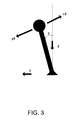
- FIG. 3 is an inverted pendulum model of a standing person.
- FIG. 4 is a block diagram illustrating single axis tilt estimation.
- FIG. 5A is a reference frame centered on the subject's body.
- FIG. 5B is a reference frame centered on the platform.
- FIG. 5C is an illustration showing various reference frames in a single situation.
- FIG. 6 is a block diagram illustrating a multi-axis tilt estimation using quaternions.
- FIG. 7 is a block diagram illustrating a multi-axis tilt estimation using Euler angles.
- FIG. 8 is a block diagram illustrating a multi-axis tilt estimation using a Kalman filter.
- FIG. 9 is an exemplary decision space for fall detection and remediation.
- a portable balance prosthesis 10 includes a motion sensing system 12 .
- Motion sensing system 12 has an output that depends on the rotational and translational motion experienced by the wearer.
- the output from the motion sensing system 12 is provided to an on-board digital signal processor 14 that provides real-time estimates of the wearer's orientation and angular velocity in three-dimensional space.
- the processor 14 detects the wearer's vertical orientation while rejecting errors caused by instrument drift and extraneous acceleration.
- the resulting estimates are then provided to an actuator 16 that drives a stimulator 18 in communication with the wearer's nervous system.
- the actuator 16 translates the real-time estimates of the wearer's orientation and velocity into a form that can be used by the wearer.
- a controller area network (CAN) bus and controllers are provided to transfer information between the sensors, the digital processor, and the stimulator.
- the prosthesis also preferably includes a wireless transmitter, which allows system parameters such as dead zone and control loop gains to be adjusted and which allows subject performance to be remotely recorded.
- the prosthesis also may have one or more batteries that supply power to the sensors, processor, and stimulator.
- the motion sensing system 12 is preferably an instrument sensor assembly (ISA).
- ISA may include three gyroscopes (“gyros”) and three accelerometers, but any number of any instruments capable of determining linear or angular changes in position may be used. Other such instruments include, for example, magnetometers.
- Micromachining or microelectromechanical systems can be used to provide small and portable sensors, e.g., as described in A. Kourepenis, J. Borenstein, et al., “Performance of MEMS Inertial Sensors,” AIAA GN & C Conference , August, 1998.
- the ISA preferably includes read-out electronics and digitizers, and a mechanism and bubble level for aligning the sensors with the subject's natural or comfortable vertical.
- a suitable, relatively low-cost ISA may be assembled using the type of sensors currently used in automobiles for air bag deployment and traction control, for example Analog Devices ADXL accelerometers and gyroscopes, or Silicon Sensing Systems gyroscopes, or Motorola accelerometers.
- Such accelerometers may have a thermal sensitivity of about 3 milligravity (mg) per ° C. and noise of about 0.23 mg/ ⁇ Hz.
- the gyroscopes may have a thermal sensitivity of about 650°/h/° C. and noise at 470°/h/ ⁇ Hz.
- Assembled ISAs exhibiting higher performance may be purchased from Honeywell, for example the HG1920 instrument sensor assembly.
- the HG 1920 ISA incorporates accelerometers whose thermal sensitivity is 0.3 mg/° C. and gyroscopes whose thermal sensitivity and noise are 10°/h/° C. and 5°/h/Hz, performance one to two orders of magnitude better than commercial automotive grade sensors.
- Stimulator 18 preferably includes an array of tactors 20 (see FIG. 2 ) to be worn close to the subject's skin, e.g., in a belt around the subject's waist and/or in columns 24 (See FIG. 2 ) mounted on the subject's front and back.
- the tactors may be worn under or over clothing.
- Each tactor is an individually addressable electromechanical vibrating element.
- the array can include tactors to indicate azimuth and vertical tactor columns 24 to indicate elevation. “Azimuth” and “vertical,” when describing tactors, are labels of convenience only; the phrases are not used to imply any structural difference between azimuth and vertical tactors. As determined by the preferences of the subject, there should be sufficiently many columns 24 to indicate the direction
- each tactor When energized, each tactor vibrates at a frequency that is readily perceived by the wearer, typically a frequency between 250 Hz and 400 Hz, e.g., 250 Hz.
- a digital controller commands individual tactor amplifiers, which drive the tactors.
- the gyroscopic and accelerometer signals discussed above are processed to obtain a tilt-angle estimate.
- the tilt's direction is transmitted to the subject by the azimuth tactors and the tilt's magnitude is transmitted by the vertical tactors.
- the number of tactors is operator selectable, based e.g. on subject preference and sensitivity. The number of tactors can be selected based on other factors.
- the prosthesis 10 also has at least one optional airbag 22 .
- the airbag is deployed when the subject is in a state in which a fall is imminent.
- the prosthesis is equipped with airbags that are positioned around the prosthesis so as to be effective if the subject should fall in any direction.
- stimulation In addition to (or instead of) tactile stimulation, other forms of stimulation are possible, e.g. one or a combination of auditory or acoustic (L. Chiari, M. Dozza, et al., “Audio-biofeedback for balance improvement: an accelerometry-based system.,” IEEE Trans Biomed Eng ., Vol. 52, No. 12, 2005, p. 2108-11.) or electric currents applied to the tongue (P. Bach-y-Rita, K. A. Kaczmarek, et al., “Form perception with a 49- point electrotactile stimulus array on the tongue: a technical note,” J Rehabil Res Dev , Vol. 35, No. 4, 1998, p. 427-30.) or skin.
- auditory or acoustic L. Chiari, M. Dozza, et al., “Audio-biofeedback for balance improvement: an accelerometry-based system.,” IEEE Trans Biomed Eng ., Vol. 52, No. 12, 2005
- the balance prosthesis converts sensor outputs to an indication of vertical and provides cues to the subject. For purposes of explanation, determination of the wearer's vertical will be presented in two parts: single axis tilt estimation, followed by the multi-axis estimations which may be used in the prosthesis.
- the subject is modeled as an inverted pendulum with its fulcrum coinciding with the subject's feet.
- the subject is modeled as having a constant height L, and is assumed to be inclined at a tilt angle ⁇ .
- the tilt angle will be modeled as a function of time, since the subject is assumed to undergo motion.
- motion refers to all aspects of an object's movement, including but not limited to position, velocity, acceleration, trajectory, etc.
- Other, more refined, models can be employed, e.g. treating the subject as a double pendulum with fulcra at the subject's waist and at the subject's feet.
- the tilt estimations described below do not depend on a particular detailed model of the subject.
- single axis estimation motion experienced by the subject includes rotation about only one axis.
- a block diagram of a single axis estimation 40 used for the prosthesis is shown in FIG. 4 .
- analog filters are shown.
- higher order digital filters also can also be used in the prosthesis.
- the single axis estimation determines the subject's tilt from gyro output 42 and accelerometer output 41 .
- the gyro output is filtered by a high-pass filter 46 and the accelerometer output is filtered by a low-pass filter 45 .
- the outputs are then combined at a combiner 47 , to produce the single-axis tilt estimation.
- S a and B a are the scale factor and bias of the accelerometer and a is the acceleration which the accelerometer experiences.
- the accelerometer output 41 should be low-pass filtered.
- L 1.5 m, which is the height of a typical person, the angular acceleration term in (2) becomes larger than g ⁇ for tilts with frequencies greater than 0.4 Hz.
- the angular acceleration term is 180 degrees out-of-phase with the desired tilt term so that wide bandwidth stabilization is difficult.
- the break frequency of the low-pass filter is set at 0.03-0.3 Hz.
- the break frequency of the low-pass filter can be computed in this manner for a subject whose height is different from 1.5 m.
- the tilt angle ⁇ is estimated by:
- ⁇ ⁇ LP ⁇ ( s ) ⁇ ( V a - B ⁇ a S ⁇ a ) + HP ⁇ ( s ) s ⁇ ( V g - B ⁇ g S ⁇ g ) ( 4 )
- carat ( ⁇ ) denotes estimated or calibrated quantities stored in computation
- LP(s) and HP(s) are the transfer functions of the low-pass filter 45 and high-pass filter 46 :
- LP ⁇ ( s ) s ⁇ ⁇ ⁇ N 2 ⁇ ( 2 ⁇ ⁇ ⁇ + 1 ) + ⁇ N 3 ( s + ⁇ N ) ⁇ ( s 2 + 2 ⁇ ⁇ ⁇ ⁇ ⁇ ⁇ N ⁇ s + ⁇ N 2 ) ( 5 )
- HP ⁇ ( s ) s s 2 + s ⁇ ⁇ ⁇ N ⁇ ( 2 ⁇ ⁇ ⁇ + 1 ) ( s + ⁇ N ) ⁇ ( s 2 + 2 ⁇ ⁇ ⁇ ⁇ N ⁇ s + ⁇ N 2 ) ( 6 )
- ⁇ N 0.03 Hz
- ⁇ 0.707
- s is the Laplace transform of the time derivative.
- references to a “low-pass filter” will mean a low-pass filter according to equation (5), and references to a “high-pass filter” will mean a high-pass filter according to equation (6), unless otherwise specified.
- Other low-pass or high-pass filters may be implemented with equal efficacy.
- the filters described above reduce accelerometer low frequency noise as the inverse of frequency squared.
- the low frequency gyro drift is proportional to frequency squared so that a bias shift does not result in a steady state offset of tilt. Filters of higher or lower order or direct digital implementations (such as impulse invariant) can be used as well.
- Implementing the gyro filtering according to equation (6) avoids numerical problems associated with integrating the gyro rate and high-pass filtering later.
- the estimated tilt is obtained from the actual tilt and other poorly modeled effects by substituting equations (1) through (3) into equation (4):
- Equation (7) Errors in calibration or changes in bias are included in equation (7) by including both the actual bias and the bias obtained from calibration. Because of the third order high-pass filter 46 described by equation (6), gyro bias errors 44 do not cause a steady shift in the estimated tilt. White gyro noise does not cause angle random walk. The effects of accelerometer noise (the unmodeled bias terms) and angular and lateral accelerations decrease two decades per decade beyond the filter break frequency of 0.03 Hz.
- the balance prosthesis estimates the vertical to within 0.1 to 1 deg.
- a 1 mg (0.0098 m/s 2 ) accelerometer bias shift causes a 0.001 radian (0.06-deg) tilt error. Since the bias is calibrated at instrument turn-on, it must be maintained for roughly 16 hours.
- accelerometer white noise 1 mg/ ⁇ Hz results in 0.2 milliradians of tilt.
- the best MEMS sensors can provide a stability of 1 mg, while 5 to 50 mg is typical of automotive grade sensors.
- accelerometer bias not gyro bias, is the limiting factor in this processing scheme.
- the gyro contributes only transient errors.
- 360-°/h/ ⁇ Hz gyro white noise typical of automotive sensors, results in 0.10 tilt error. The maximum allowable transient tilt error for a balance impaired subject to fall is not presently known.
- the ability to estimate the tilt that results from complicated motion including rotation about multiple axes is desirable, because such complicated motion more closely describes people in day-to-day tasks than does motion limited to rotation about a single axis.
- One simple strategy to estimate multi-axis tilt is that of employing several instrument sensor assemblies along multiple axes, each configured to perform single-axis tilt estimation.
- Each instrument sensor assembly has a corresponding axis about which it detects the tilt of the subject.
- the single-axis tilt estimation is based in part on the instruments having particular spatial orientations relative to each other.
- the relative spatial orientations of the instruments are not changed in a manner which affects the estimation.
- the assembly's instruments' relative orientations change in a manner which will affect the estimation performed by the assembly.
- the single-axis assembly does not account for its own tilt about an axis different from the one it measures tilt relative to.
- an estimate of the subject's tilt made by combining two single-axis tilt estimates may be off by as much as 20 degrees.
- the single-axis estimation discussed to account for the changes in the spatial orientations of the instruments that occur as the subject rotates about multiple distinct axes.
- the multi-axis algorithm can be implemented using quaternions.
- other implementations are possible, such as the use of Euler angles and Kalman filters.
- the following description of the multi-axis implementation relies on the following basic principles and notational conventions for quaternions.
- a quaternion is a particular type of number. As used herein, a quaternion has four parameters, also called components. The first parameter is sometimes referred to as “real,” while the last three parameters are sometimes referred to as “complex.” The symbols i, j, and k are often used to signify the three complex parameters. We may write a general quaternion by specifying its four parameters, for example:
- Quaternions can be multiplied.
- One way to define quaternion multiplication of quaternions Q and P with components [q 1 , q 2 , q 3 , q 4 ] and [p 1 , p 2 , p 3 , p 4 ] respectively, is to define the components of their product, denoted Q**P as:
- conjugate( Q ) [ q 1 , ⁇ q 2 , ⁇ q 3 , ⁇ q 4 ]. (11)
- Some quaternions can be used to describe geometric points in space, or vectors.
- the three complex components can be thought of as representing the three Cartesian coordinates of a point in space. Equivalently, the three complex components can be used to define a vector in space anchored to the origin. For this reason, the first component of a quaternion is sometimes referred to as the “scalar” component, and the last three components are referred to as “vector” components.
- Some quaternions can also define rotations of the vectors (and equivalently, reference frames).
- the quaternion Q can be referred to as a “rotation quaternion.”
- coordinate frame A is related to coordinate frame B by a rotation, with the rotation being described by a quaternion Q.
- the rotation quaternions are related to the angular velocity of the reference frame by:
- Equation (14) is particularly useful for inertial guidance or for an all gyro balance prosthesis, because the angular rates are measured directly (after bias and misalignment compensation) by the three gyroscopes.
- the integrations are straightforward for first order differential equations with no singular points.
- the amplitude of the rotation is defined by the scalar vector of the quaternion.
- the “axle” about which the rotation is executed is defined by the vector component of the quaternion. Note that the quaternion representing transformation from frame A back to frame B is given by the conjugate of the transformation from frame B to frame A. This is equivalent to replacing the angle by its negative.
- a reference frame is a set of axes which can be used to specify the location of a point or an object in space.
- An “orthogonal” reference frame is one in which the axes are mutually perpendicular.
- the term “coordinate frame” is synonymous with “reference frame.”
- To specify the location of a general point in space at least three axes are required. For a given reference frame, these axes are typically labeled “x,” “y,” and “z.”
- primes (′) will be used to distinguish, e.g., the x-axis in one reference frame with the x′-axis of another.
- the “local frame” is defined to be an orthogonal frame oriented with respect to the Earth so that its z-axis is aligned with the direction of gravity. In this definition, the Earth can be considered flat and the rotation of the Earth can be considered negligible.
- the x and y axes may be defined in any convenient way, so long as the local frame remains orthogonal. For example, the x and y axes of the local frame may be chosen to correspond to the nominal x and y axes of the body frame, as described below.
- the “body frame” is attached to the subject's trunk or head, with the z-axis lying substantially parallel to the subject's spine.
- the z-axis is oriented so that movement in the positive z-direction corresponds to movement from the subject's head to the subject's feet.
- the y-axis is oriented to be generally parallel to the subject's outstretched arms (with the positive y coordinates lying to the subject's right).
- the x axis is oriented to be generally perpendicular to the subject's chest (with positive x coordinates lying in front of the subject).
- the roll, pitch, and yaw axes are synonymous with the x, y, and z axes of the body frame, respectively. Coordinates of a point as measured in some reference frame may be converted to coordinates measured in the body frame by conventional methods if the pitch, roll, and yaw angles are known.
- FIG. 5A a subject is shown in two positions. When standing generally upright, the x, y, and z axes of the body frame are as indicated on the left. When bending over, the x, y, and z axes of the body frame are as indicated on the right.
- the “platform frame” is an orthogonal frame defined by the input axes of inertial instruments. Alternatively, the platform frame can be defined by reference surfaces upon which the instrument sensor assembly is mounted.
- the prosthesis contains six instruments: three gyros and three accelerometers. Each instrument has its own input axis. The input axis of an instrument determines what the instrument measures: an accelerometer measures acceleration in the direction of its input axis, and a gyro measures rotation about its input axis.
- the accelerometers' input axes would all be mutually perpendicular, and the gyros' input axes would all be mutually perpendicular. (Equivalently, pairs of accelerometer input axes or pairs of gyro axes would coincide with reference surfaces). These cases are ideal because the input axes of the prosthesis can then be used to define an orthogonal frame in which the prosthesis has a fixed orientation. However, it is often impractical to install the accelerometers and the gyros with this precision, or to expect the sensors' axes to be aligned with a reference surface.
- the platform frame 50 b may be defined as follows. Any of the six instruments in the prosthesis is selected arbitrarily. For illustration, an accelerometer 51 b is selected, although the following procedure can be carried out using a gyro.
- the x axis of the platform frame is defined to coincide with the input axis (not shown) of the accelerometer 51 b.
- the input axes 53 b , 55 b of the remaining accelerometers 52 b , 54 b generally do not coincide with the platform axes, because the input axes 53 b , 55 b of the accelerometers need not be mutually perpendicular and the platform axes must be. Thus, there generally are two “misalignment angles” between each accelerometer's input axis and a given platform axis.
- a second accelerometer 52 b is selected, and the y axis is chosen so that this second accelerometer is misaligned with the y axis with only one nonzero angle of misalignment.
- misalignment angle is of the second accelerometer 52 b is denoted ⁇ 5z , because the accelerometer 52 b is rotated by this angle about the z axis from aligning with the y axis.
- the input axes 53 b , 55 b of the accelerometers 52 b , 54 b are nearly parallel to the platform axes, so that one can refer to, e.g., a “nominally y accelerometer” as being the accelerometer whose input axis is closest to they axis of the platform frame.
- nominally implies that the input axis of the instrument in question need not exactly coincide with the specified axis.
- the nominally x, y, and z accelerometers 51 b , 52 b , 54 b respectively are shown in FIG. 5B .
- FIG. 5C shows a subject 50 c (shown schematically) leaning forward while wearing the prosthesis 51 c (shown schematically), with all of the reference frames described above shown.
- the direction of gravity is indicated by the arrow g.
- the local frame is labeled by x, y, and z axes. Note that the z axis is parallel to the direction of gravity.
- the body frame is labeled by x′, y′, and z′ axes. Note that the z′ axis is parallel to the subject's torso 52 c .
- the platform frame is labeled by x′′, y′′, and z′′ axes. Note that no axis of the platform frame is parallel to any axis of the body frame. I.e., the body-to-platform misalignment angles are all nonzero.
- the above reference frames are each convenient for particular tasks or contexts.
- the local frame is a convenient frame in which to calculate the effect of gravity on the individual instruments, because gravity is always aligned with the local frame's z axis.
- the platform frame is a convenient frame to in which to manipulate the data obtained by all the instruments, because in the platform frame the instruments have a fixed position.
- the body frame is a convenient frame to make calculations related to presenting stimulus to the subject, so that the subject need not make mental calculations to make sense of the stimulus. Other tasks or calculations are convenient in each of the above reference frames.
- the misalignment of the other accelerometer input axes with respect to the platform axes are defined by the non-orthogonal matrix:
- the misalignment of the gyroscope input axes with respect to the platform axes is defined by the non-orthogonal matrix:
- the general approach to determining the tilt angles of the subject is to detect the direction of gravity in the platform frame. Both accelerometer and gyro information is used to determine this.
- the direction of gravity as determined by each of the accelerometers and gyros can be displayed as a quaternion.
- quaternions determined from the accelerometers and from the gyros are combined to obtain a total quaternion. The total quaternion provides a more reliable estimate of the subject's tilt because the individual gyro or accelerometer quaternions have been filtered prior to being combined. As with the single-axis case, filtering removes errors associate with drift, bias, or noise of the respective instruments.
- FIG. 6 shows a multi-axis estimate of the subject's tilt using quaternions.
- a gyro quaternion 63 denoted Q g will be used to rotate the platform frame into the local frame. From the gyro output 60 one can directly calculate the gyro quaternion 63 .
- a horizontal quaternion 61 is calculated without knowledge of azimuth and is independent of azimuth gyro drift (which can be difficult to directly determine).
- drift in the nominally horizontal gyro is removed by using the accelerometers for low frequencies.
- Q g transforms a vector in the platform frame to the local frame by rotating an appropriate angle about a horizontal axis, followed by an appropriate rotation about a vertical axis.
- the quaternion Q H implementing the horizontal rotation is called the horizontal quaternion 61
- the quaternion Q V implementing the vertical rotation is called the vertical quaternion 62 .
- the angular rate of the platform can be measured by the gyroscopes after compensating for bias, scale factor, and angular misalignments. Using these measurements, one can determine the gyro quaternion 63 through the equation:
- none of the time derivatives includes the azimuth angle ⁇ . This allows the high-pass filter 64 and low-pass filter to act on the gyro signal 60 and accelerometer signal 65 respectively, so that h 1 , h 2 , and h 3 will approach the accelerometer-determined values.
- the h terms determine the horizontal quaternion 61 as above, which transforms a vector from the platform coordinates to a frame rotating about the vertical at the yaw rate.
- the gyro output 60 is obtained by transforming angular rates from gyro to platform coordinates.
- Each gyro is linearly modeled as a scale factor plus bias. Linear cross-axis terms are included in the misalignment angles defined by equation (18).
- the platform rates are solved directly from the three instrument voltages:
- the accelerometer output 65 which is thus determined by gravity as defined in the platform frame, is:
- the horizontal quaternion 61 determined by equation (19) and the accelerometer quaternion 66 determined by equation (26) are similar in form.
- the derivative h′ will be calculated inaccurately. Therefore, after an initial estimate is made, the derivatives are subsequently obtained from the total quaternion 68 . That is, the gyro quaternion 63 updates (19) as according to the equations:
- the accelerometer quaternion 66 is determined from acceleration ratios, its magnitude is always equal to 1 as expected for a rotation quaternion.
- the total quaternion 68 is normalized to 1 but the gyro quaternion 63 is not.
- the complementary filters 64 , 67 correctly extract the gyro quaternion's oscillating portion so that the total quaternion 68 is close to 1.
- the gyro quaternion 63 is inserted into the complementary filters 64 , 67 , which are numerically integrated by a second order Runge-Kutta (B. Carnahan, H. A. Luther, and J. O. Wilkes, Applied Numerical Methods , John Wiley And Sons, New York, 1969).
- Equation (28) could be added to equation (28) so that numerical or physical instabilities dampen over time.
- the total quaternion terms in equation (28) could be replaced with the low-passed terms derived from the accelerometers.
- the total quaternion 68 is used to determine when to fire tactors and which tactors to fire.
- h 1T defines the magnitude of the rotation as described in the Convention for Quaternions section above, or, by inspection of (29), all three terms can be employed.
- ⁇ circumflex over ( ⁇ ) ⁇ a tan 2( ⁇ square root over ( ⁇ 2 + ⁇ y 2 ) ⁇ , ⁇ z )0 ⁇ (30)
- the firing angle ⁇ is the azimuth angle indicating the direction toward which the subject should move to correct his posture.
- the acceleration sensed by the x-axis accelerometer is positive, which means the sensed g x is negative. Consistent with (31), the front tactor will be commanded to vibrate. As another example, assume the subject leans forward and right. In this case, the x and y accelerometers will indicate positive gravity (negative acceleration). Therefore the tactors behind and to the left of the subject will vibrate.
- the tactors drive the subject to the nulls defined by the sensors' output signals. Because of the complementary filters 64 , 67 , the low frequency (below 0.03 Hz) null is determined by the accelerometers. The prosthesis is therefore initialized to align the subject's comfortable vertical with that indicated by the accelerometers.
- the sensors' bias (the output signal when no acceleration or angular rate is applied) can drift between factory (test station) calibration and field tests with subjects. Changing instrument bias is equivalent to the instrument's null changing with time.
- the prosthesis Beforehand, on a test station, the prosthesis undergoes a stationary calibration in which each sensor's bias, scale factor, and the misalignment angles with respect to the ISA reference plane are calibrated. Because the balance prosthesis seeks to null the sensor outputs, the sensor bias, and particularly accelerometer bias, is generally more important than the scale factor. Thus, initialization focuses on instrument-to-platform and platform-to-body misalignment angles and sensor bias.
- the stationary calibration can be performed by measuring a lumped bias or by assuming the factory bias and determining the body-to-platform misalignments.
- the lumped bias approach combines the accelerometer bias and alignment angles.
- the instrument sensory assembly (ISA) is mounted on the subject and adjusted to be nearly level, using, for example, a bubble level on the ISA.
- the leveling implies that the sensor input axes are close to horizontal and vertical. Thus, misalignments between the subject's vertical and the ISA are small angles.
- the subject stands vertical long enough to accomplish the initialization, for example one second.
- the gyro outputs are recorded as gyro bias.
- the horizontal accelerometer outputs contain sensor bias plus misalignment times gravity terms. These are automatically entered as a bias (the “lumped” bias).
- the lumped bias effectively nulls the accelerometers to the subject's comfortable vertical and removes accelerometer drift.
- the angles between the accelerometers and subject vertical are not known; however, for low frequency and steady state, the ISA will drive the subject to his vertical. Because the angles are not known, the knowledge of the vertical at high frequencies (gyro alignment is assumed small) and high roll and pitch angles is not perfect but sufficient for null-seeking prostheses.
- the periodic bias calibration allows less costly instruments to be used.
- a second option is to assume that accelerometer bias is constant and does not require periodic recalibration.
- a third option is to provide a simple calibration fixture so that the sensors' bias can be measured immediately before mounting the ISA to the subject. Accelerometer bias can be calculated from the average of its outputs after the input axis is initially aligned up and then its alignment is reversed. This procedure is relatively insensitive to alignment angles and can be done without a precise test table.
- the on-subject initialization one can solve for the misalignments of the accelerometers and employ the factory-supplied misalignments of the gyros with respect to the accelerometers.
- vibrating elements other than tactors may be used to deliver information to the subject.
- signals other than tactile signals can be provided to the subject.
- an acoustic signal can be delivered through a headset or a visual signal can be delivered by selectively illuminating light sources.
- multi-axis estimation methods for example estimates based on Euler angles, redundant Euler angles, or estimates made using a Kalman filter. Examples of these types of multi-axis estimates are given below.
- Euler angles are similar to misalignment angles described above.
- roll, pitch, and yaw angles are used to describe Euler angles. Other angles may be used.
- the prosthesis determines the roll and pitch angles of the subject with respect to local coordinates as described below. Determining the yaw angle is of little importance, because motion consisting of purely changing yaw (e.g. standing still at the center of a slowly spinning merry-go-round) poses little danger to vestibulopathic subjects.
- the transformation from local coordinates to the body frame is calculated by:
- the angular rates sensed in the body frame are related to the derivatives of the Euler angles through:
- Transformations (32) through (35) are orthogonal so that their respective transposes are also their inverses. Transformation (37), however, is not orthogonal.
- the outputs of the gyros are obtained by transforming roll, pitch and yaw rates into components along the gyros' input axes.
- Each gyro is modeled as a simple bias plus scale factor.
- the output signals are:
- [ V 1 V 2 V 3 ] [ B 1 B 2 B 3 ] + C p g ⁇ C b p ⁇ [ S 1 ⁇ [ R . - sin ⁇ ( P ) ⁇ Y . ] S 2 ⁇ [ cos ⁇ ( P ) ⁇ sin ⁇ ( R ) ⁇ Y . + cos ⁇ ( R ) ⁇ P . ] S 3 ⁇ [ cos ⁇ ( P ) ⁇ cos ⁇ ( R ) ⁇ Y . - sin ⁇ ( R ) ⁇ P . ] ] ( 42 )
- each gyro senses a single rate. This results in two single-axis feedback loops. As expected, the outputs in equation (42) do not depend on the yaw angle.
- the accelerometer outputs are determined by:
- V 4 V 5 V 6 [ B 4 B 5 B 6 ] + [ S 4 0 0 0 S 5 0 0 0 S 6 ] ⁇ C p a ⁇ C b p ⁇ C L b ⁇ [ 0 0 - g ] ( 43 )
- the V terms represent the output voltages of the accelerometers. Equation (43) assumes that the accelerometer input axis is aligned nominally with +z (down) so that gravity causes a negative voltage. Including the body-to-platform and accelerometer-to-platform misalignments in the previous equation, the accelerometer outputs from gravity are:
- V 4 V 5 V 6 ] [ B 4 + gS 4 ⁇ [ sin ⁇ ( P ) ] B 5 - gS 5 ⁇ [ cos ⁇ ( P ) ⁇ sin ⁇ ( R ) ] B 6 - gS 6 ⁇ [ cos ⁇ ( P ) ⁇ cos ⁇ ( R ) ] ] + [ gS 4 ⁇ [ - ⁇ z ⁇ cos ⁇ ( P ) ⁇ sin ⁇ ( R ) + ⁇ y ⁇ cos ⁇ ( P ) ⁇ cos ⁇ ( R ) ] - gS 5 ⁇ [ ⁇ x ⁇ cos ⁇ ( R ) ⁇ cos ⁇ ( P ) + ( ⁇ z + ⁇ 5 ⁇ z ) ⁇ sin ⁇ ( P ) ] + gS 6 ⁇ [ ( ⁇ x + ⁇ 6 ⁇ x ) ⁇ cos ⁇ ( P ) ⁇ sin ⁇ ( R )
- a more detailed representation can also include lateral accelerations of the body frame.
- the accelerometer outputs are low-pass filtered, to remove the effect of the lateral accelerations on the measurement. Thus, there is no need to account for them in equation (44).
- FIG. 7 shows how the Euler angles of the subject are calculated.
- Either the gyro (42) or accelerometer (44) equations can be solved to obtain roll and pitch angles.
- the gyro equations determine a high-frequency roll estimate 71 and a high-frequency pitch estimate 72 ; and the accelerometer equations will determine a low-frequency roll estimate 75 and a low-frequency pitch estimate 76 .
- the accelerometer signals contain angular and lateral accelerations and because gyro drift is integrated to obtain the roll and pitch, it is desirable to calculate the roll and pitch by low-pass filtering the output of the accelerometers and by high-pass filtering the output of from the gyroscopes.
- the low-frequency roll estimate 75 and pitch estimate 76 are obtained from the accelerometer outputs 74 by inverting equation (44) and filtering through a low-pass filter 77 :
- R ⁇ L atan ⁇ ⁇ 2 ⁇ ⁇ - a ⁇ 5 p , - a ⁇ 6 p ⁇ * L p ( 45 )
- P ⁇ L atan ⁇ ⁇ 2 ⁇ [ a ⁇ 4 p , - a ⁇ 6 p cos ⁇ R ⁇ , ] * L p ( 46 )
- a ⁇ p C ⁇ a p ⁇ [ S ⁇ 4 0 0 0 S ⁇ 5 0 0 0 S ⁇ 6 ] - 1 ⁇ [ V 4 - B ⁇ 4 V 5 - B ⁇ 5 V 6 - B ⁇ 6 ] ,
- Equation (46) the roll estimated from both the gyros and accelerometers is used.
- ⁇ circumflex over (R) ⁇ in equation (46) can be replaced with ⁇ circumflex over (R) ⁇ L . From equation (42), one obtains the Euler angle rates from the measured gyro outputs 70 . These are, with misalignment angles omitted and high-pass filter 73 included,
- R ⁇ . H [ sin ⁇ P ⁇ ⁇ cos ⁇ R ⁇ ⁇ ( V 3 - B ⁇ 3 ) S ⁇ 3 ⁇ cos ⁇ ⁇ P ⁇ + sin ⁇ P ⁇ ⁇ sin ⁇ R ⁇ ⁇ ( V 2 - B ⁇ 2 ) S ⁇ 2 ⁇ cos ⁇ P ⁇ + ( V 1 - B ⁇ 1 ) S ⁇ 1 ] * H p ( 47 ) P ⁇ .
- H [ cos ⁇ R ⁇ ⁇ ( V 2 - B ⁇ 2 ) S ⁇ 2 - sin ⁇ R ⁇ ⁇ ( V 3 - B ⁇ 3 ) S ⁇ 3 ] * H p ( 48 ) Y ⁇ .
- H [ cos ⁇ R ⁇ ⁇ ( V 3 - B ⁇ 3 ) S ⁇ 3 ⁇ cos ⁇ P ⁇ + sin ⁇ R ⁇ ⁇ ( V 2 - B ⁇ 2 ) S ⁇ 2 ⁇ cos ⁇ P ⁇ ] * H p ( 49 )
- H p is the high-pass filter described by equation (6).
- the angular rates specified in equations (47)-(49) employ the combined roll 78 and pitch 79 , as described in equations (50)-(51). This reduces accumulation of drift during gyro integration.
- the angular rates for roll and pitch can be directly integrated to obtain a high-frequency roll estimate 72 and a high-frequency pitch estimate 73 .
- Equation (49) The integral of yaw rate in equation (49) is not used since the yaw angle appears in no other expressions.
- the low-frequency roll estimate 75 and pitch estimate 76 do not depend on prior knowledge of the roll and pitch. As long as the accelerometer coefficients are known, the low frequency angles are determined and the subject will stand about his vertical on the average. Additionally, small damping terms could be added to equations (47) and (48) so that numerical or physical instabilities dampen over time. The total pitch and roll terms could be replaced with the low passed terms derived from the accelerometers.
- Another approach involves a fourth, redundant Euler angle whose function is similar to the redundant gimbal in inertial navigation systems.
- the redundant Euler angle is added to the traditional yaw, pitch, and roll angles.
- the redundant Euler angle is selected so that the pitch angle remains near null, thereby avoiding effective gimbal lock.
- This approach allows the accelerometers to estimate low frequency components of tilt (below 0.03-0.3 Hz) while the gyros estimate the higher frequency components without requiring low frequency yaw information. This formulation is useful because the accelerometers only yield information about tilt and not azimuth.
- the redundant Euler angle is implemented as follows.
- the transformation from local coordinates to body coordinates is calculated by:
- C L b C J C r C p C y (53) where C r , C p , and C y are as above and C J is rotation about the redundant angle, defined by:
- the angular rates sensed in the body frame are related to the derivatives of the Euler angles through:
- the subscript “Lb” indicates that the rate is that of the body with respect to the local frame and the superscript “b” indicates that the quantities are measured or defined in the body frame.
- the C a b transformation is not orthogonal. For ease of explanation, it is assumed that the instruments are aligned with the body frame. This assumption can be relaxed by introducing additional transformations to account for misalignment, as was done above.
- the gravity vector g y is fixed in the yaw frame and takes the form:
- a vector defined in the yaw frame is transformed into body coordinates by the transformation:
- the gravity vector in the body frame is:
- g b [ - cos ⁇ ( P ) ⁇ cos ⁇ ( R ) ⁇ sin ⁇ ( J ) - cos ⁇ ( J ) ⁇ sin ⁇ ( P ) cos ⁇ ( P ) ⁇ sin ⁇ ( R ) cos ⁇ ( J ) ⁇ cos ⁇ ( P ) ⁇ cos ⁇ ( R ) - sin ⁇ ( J ) ⁇ sin ⁇ ( P ) ] ⁇ g . ( 58 )
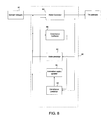
- FIG. 8 shows a thirteen-state extended Kalman filter 80 that can be used to obtain tilt estimates using the sensor platform.
- the thirteen states include six first-order Markov processes for low frequency sensor drifts, three first-order Markov processes for angular rate, and four states for propagating the quaternions representing the subject's tilt. It is emphasized that Kalman filters can be designed with more or fewer states, but that the underlying principles are similar.
- the Markov processes for the sensors coupled with the wide bandwidth noise on the sensor output shape the Kalman filter to a response similar to that of the high- and low-pass filters described above.
- the gyro and accelerometer biases are modeled as first-order Markov processes and wide bandwidth noise.
- the body frame input angular rates are also modeled as first-order Markov processes.
- the angular rates are related to the quaternions, which define angular orientation, through the nonlinear first-order quaternion differential equation (14).
- Three gyro biases, three accelerometer biases, three angular rates, and four quaternions result in thirteen states.
- the Markov process appears in the state vectors while the wide bandwidth noise is output noise.
- the Markov processes for sensor bias and input angular rate are modeled as:
- q . 1 - 1 2 ⁇ ( ⁇ 1 ⁇ q 2 + ⁇ 2 ⁇ q 3 + ⁇ 3 ⁇ q 4 ) ( 65 )
- q . 2 1 2 ⁇ ( ⁇ 1 ⁇ q 1 - ⁇ 2 ⁇ q 4 + ⁇ 3 ⁇ q 3 ) ( 66 )
- q . 3 1 2 ⁇ ( ⁇ 1 ⁇ q 4 + ⁇ 2 ⁇ q 1 - ⁇ 3 ⁇ q 2 ) ( 67 ) q .
- x ⁇ ⁇ [ x ⁇ 1 - 9 T q 1 q 2 q 3 q 4 ] T ( 69 )
- the gyro outputs are linearly related to the input rate and gyro bias by:
- V g ⁇ ⁇ 1 V g ⁇ ⁇ 2 V g ⁇ ⁇ 3 ] [ I 3 ⁇ 3 O 3 ⁇ 3 I 3 ⁇ 3 O 3 ⁇ 4 ] ⁇ x ⁇ + [ V g ⁇ ⁇ n ⁇ ⁇ 1 V gn ⁇ ⁇ 2 V gn ⁇ ⁇ 3 ] , ( 70 )
- V g is the gyro output (measured in rad/s)
- V gn gyro additive white noise
- I is the identity matrix
- O is the zero matrix.
- the accelerometer outputs are linearly related to the accelerometer bias and are nonlinear in the quaternions that transform gravity into body coordinates.
- the unwanted high frequency subject accelerations are represented by additive white noise. Additional states could more flexibly represent high frequency accelerations.
- the accelerometer outputs are linearly related to the input rate and accelerometer bias by:
- the gyro noise is typically that of a commercial gyro, while the accelerometer noise is selected to yield accelerometer frequencies near 0.03 Hz as used in the complementary filters. Both the measurement and input noise are assumed to be zero mean, with the measurement noise not correlated to the input noise. These assumptions can be relaxed according to known techniques.
- the combined output vector is defined by:
- the continuous linear model described above it is convenient to convert the continuous linear model described above to the discrete domain. In an exemplary embodiment, this is done by assuming a 0.01 s sampling interval, T s , and that other inputs are constant across the sampling interval.
- the zero order hold (ZOH) assumption is also made, as described in K. Ogata, “Modern Control Engineering”, Prentice-Hall, Englewood Cliffs, N.J., 1970.
- the power spectral densities of the continuous case are transformed to covariance by integrating the white noise power spectral densities (PSDs) from minus Nyquist to Nyquist frequency.
- the Nyquist frequency is 0.5/T s .
- the Kalman filter will cycle between two phases: prediction and correction.
- the prediction phase the Kalman filter will predict the subject's state at the time of the next measurement, based on the subject's previously corrected state.
- the correction phase the Kalman filter will account for differences between the subject's predicted state and the subject's actual state, as determined from the measurement.
- the subject's state at the time of the next measurement is predicted by a state predictor 82
- the covariance at that time is predicted by a covariance predictor 83 .
- the predictors 82 , 83 calculate a new state and covariance, respectively, according to the formulas
- the numerical integration starts with initial conditions ⁇ right arrow over ( ⁇ circumflex over (x) ⁇ k (+) and ends at ⁇ right arrow over ( ⁇ circumflex over (x) ⁇ k+1 ( ⁇ ).
- the matrices A and B are calculated by linearizing equations (53)-(62).
- the ZOH discrete matrices A z and B z are recalculated at each step, periodically, or when the state estimates exceed certain value.
- zero mean noise inputs are omitted.
- the predicted state estimate is corrected by a state corrector 84 .
- the nonlinear function H is obtained from equations 70-72.
- the matrix M k is called the innovation matrix. Generally, the innovation matrix accounts for differences between the predicted state and the measured state.
- the covariance is corrected after the measurement by a covariance corrector 86 .
- the corrected covariance Z k is determined from the formula:
- any of the multi-axis, large angle vertical detection algorithms estimate the elevation angle ⁇ and the azimuth angle ⁇ .
- the azimuth indicates the direction toward which the subject's head should move for the subject to attain vertical.
- the elevation is restricted to 0 to ⁇ radians, and indicates how far the subject has moved from vertical. For a given elevation angle, if the elevation angle is changing faster than a certain threshold, one would expect that the risk of a fall is heightened. If the elevation angle is beyond a different threshold, one would expect a fall is imminent. In either case, it is useful to trigger remedial action.
- An exemplary decision space 90 is used to determine when to trigger remedial action, and what type of action is called for.
- the subject has a particular elevation which is changing at an acceptably low rate, the subject is within the “safe zone” 91 and no remedial action is triggered.
- the subject's elevation may change at a rate less than
- the subject is outside the safe zone, and remedial action will be taken.
- a negative rate larger than the positive rate may be permissible, since, a negative rate would indicate that the subject is moving toward the vertical.
- the decision space may be partitioned into several regions, one of which being the safe zone 91 .
- Other regions correspond to different remedial actions.
- region 92 may be chosen to reflect situations in which the subject bears a heightened (but not imminent) risk of falling.
- remedial action such as sounding an alarm or providing additional stimulus to the subject may be taken.
- Region 93 may be chosen to reflect situations in which a fall is imminent.
- remedial action intended to mitigate the adverse effects of the fall may be taken.
- the prosthesis may: deploy an airbag or initiate an automated call for help.
Abstract
Description
V a =S a a+B a (1)
where, Sa and Ba are the scale factor and bias of the accelerometer and a is the acceleration which the accelerometer experiences. For ease of explanation, it is assumed that the subject's tilt angle and the initial offset angle of the accelerometer are small, allowing small-angle approximations to be employed. The estimation may be employed without making these approximations. Assuming small-angle approximations for the tilt angle θ and the initial offset α, the input acceleration is given by:
a=g(θ+α)−L{umlaut over (θ)}+a h (2)
-
- Where g=acceleration due to gravity (9.8 m/s2)
- α=initial offset between accelerometer input axis and subject's vertical
- L=Height of the subject, with the subject modeled as an inverted pendulum as shown in
FIG. 3 . - θ=angle between subject's position and subject's vertical
- ah=horizontal acceleration of the pendulum pivot
V g =S g{dot over (θ)}+Bg (3)
where, Sg and Bg are the scale factor and bias of the gyro respectively. To obtain a good estimate of
where carat (^) denotes estimated or calibrated quantities stored in computation and LP(s) and HP(s) are the transfer functions of the low-
where ωN=0.03 Hz, ζ=0.707, and s is the Laplace transform of the time derivative. In this document, references to a “low-pass filter” will mean a low-pass filter according to equation (5), and references to a “high-pass filter” will mean a high-pass filter according to equation (6), unless otherwise specified. Other low-pass or high-pass filters may be implemented with equal efficacy. The filters described above reduce accelerometer low frequency noise as the inverse of frequency squared. The low frequency gyro drift is proportional to frequency squared so that a bias shift does not result in a steady state offset of tilt. Filters of higher or lower order or direct digital implementations (such as impulse invariant) can be used as well.
Errors in calibration or changes in bias are included in equation (7) by including both the actual bias and the bias obtained from calibration. Because of the third order high-
{circumflex over (B)} a =B a +S a gα (8)
(where the top component is the first component.) Equivalently, quaternions represented using the “i, j, k” notation can be multiplied like ordinary polynomials subject to the rules i2=j2=k2=ijk=−1. Note that quaternion multiplication is not commutative. That is, Q**P need not equal P**Q.
conjugate(Q)=[q 1 ,−q 2 ,−q 3 ,−q 4]. (11)
q 1 2 +q 2 2 +q 3 2 +q 4 2=1 (12)
In this case, the quaternion Q can be referred to as a “rotation quaternion.” The square root of the expression on the left hand side of equation (12) is called the “magnitude” of the quaternion Q=[q1, q2, q3, q4].
{right arrow over (V)} B =Q**{right arrow over (V)} A**conjugate(Q) (13)
(where the vectors in both coordinate frame A and coordinate frame B are assumed to be written in quaternion form, as described above.) The rotation quaternions are related to the angular velocity of the reference frame by:
where {right arrow over (ω)}p is the angular rotation rate of frame A with respect to frame B, expressed in the coordinates of frame A.
where β=misalignment angle about subscripted axis of the platform frame. Calibrating the misalignment angles between the platform frame and the body frame is discussed in the “Initialization” sections after equations (7) and (31).
where the α terms are the misalignment angles of the accelerometers with respect to the platform frame, defined above.
where the α terms are defined analogously to the accelerometer case, as described above.
Q g =Q V **Q H (19)
a rotation quaternion about the vertical
-
- θ=rotation about the vertical of inertial space with respect to the platform
- QH=[h1 h2 h3 0], a rotation quaternion about the horizontal
- ** indicates quaternion multiplication
{right arrow over (ω)}p=[0,ω1 pω2 pω3 p]. (20)
where the prime (′) indicates differentiation with respect to time t. To avoid clutter, in (22), the superscript p has been dropped.
where
-
- V=instrument output voltage,
- B=instrument bias,
- S=instrument scale factor,
- ω=rates measured in platform coordinates, and subscripts 1-3 refer to the individual gyros
In which gravity is a negative acceleration. From the
{right arrow over (ĝ)}p=[0,ĝ1,ĝ2,ĝ3] (25)
The rotation quaternion about a horizontal axis for rotating gravity from platform coordinates to earth-fixed coordinates is:
where φ is the angle of rotation satisfying:
This quaternion, Qa, is called the
Blending of the Quaternions
{circumflex over (Q)} T(s)=L p(s){circumflex over (Q)} a(s)+H p(s){circumflex over (Q)} g(s) (27)
The Gyro Quaternion Differential Equations
where the subscript “g” indicates a gyro quaternion from equation (22), the subscript “T” indicates a total quaternion from equation (27), and the ωi terms indicate the angular rates measured by the respective gyros and transformed into platform coordinates.
ĝ x=−2h 1T h 3T
ĝ y=2h 1T h 2T
ĝ z =h 1T 2 −h 2T 2 −h 3T 2 (29)
{circumflex over (φ)}=a tan 2(√{square root over (ĝ 2 +ĝ y 2)},ĝ z)0≦φ≦π (30)
{circumflex over (φ)}=a tan 2[ĝ y ,ĝ x ]+π=a tan 2[−ĝ y ,−ĝ x ]=a tan 2[−h 2T ,h 3T] (31)
and P is the pitch angle, R is the roll angle, and Y is the yaw angle.
where the V terms represent the output voltages of each gyro, and Cb p, Cp g are matrices given by equations (16) and (28) respectively. The gyro outputs are obtained from inserting equation (37) into equation (41):
where the V terms represent the output voltages of the accelerometers. Equation (43) assumes that the accelerometer input axis is aligned nominally with +z (down) so that gravity causes a negative voltage. Including the body-to-platform and accelerometer-to-platform misalignments in the previous equation, the accelerometer outputs from gravity are:
This equation accounts for all the misalignment terms. A more detailed representation can also include lateral accelerations of the body frame. In what follows, the accelerometer outputs are low-pass filtered, to remove the effect of the lateral accelerations on the measurement. Thus, there is no need to account for them in equation (44).
Euler Angle Estimate
-
- where {circumflex over (R)}L, {circumflex over (P)}L=low frequency portion of roll, and pitch estimates
- *=convolution operator
- Lp=low-pass filter (see equation 5)
- a tan 2=two argument arc tangent. Here a tan 2(yx)=a tan(y/x) in the first quadrant
- âp=acceleration in platform frame based on measurement in accelerometer frame, i.e.
{circumflex over (P)}={circumflex over (P)} L +{circumflex over (P)} H (50)
{circumflex over (R)}={circumflex over (R)} L +{circumflex over (R)} H (51)
H p(s)=1−L p(s) (52)
CL b=CJCrCpCy (53)
where Cr, Cp, and Cy are as above and CJ is rotation about the redundant angle, defined by:
where
{dot over (R)}=sin(J)(ωz−ωx cos(R)tan(P))+cos(J)(ωx+ωz cos(R)tan(P))
{dot over (P)}=(−ωz cos(J)+ωx sin(J))sin(R)+cos(R)(ωy −{dot over (J)})
{dot over (Y)}=sec(P)(ωz cos(J)cos(R))−ωx cos(R)sin(J)+sin(R)(ωy −{dot over (J)}) (59)
where P, R, J and Y, are functions of time. In addition to these three equations, a control law for both the accelerometer and gyro equations,
{dot over (J)}=Pk p if cos(R)≧0, otherwise {dot over (J)}=−Pk p
is added, where kp is a positive constant. In an exemplary embodiment, kp is between 20 and 100 radians/second. Thus, a system of four equations in four variables is obtained. Such a system can be solved using ordinary methods. The solution, which is based on the outputs of the gyroscopes, can be combined with the accelerometer output as described above to yield a total measurement of the wearer's tilt.
Kalman Filter
where {right arrow over (x)}1-9 represents a state vector; {right arrow over (w)} represents a white noise vector; Bg is gyro bias; Ba is accelerometer bias; ω is angular rate; subscripts 1-3 indicate sensor axes nominally aligned with roll, pitch, and yaw respectively; ωa and ωg are the break frequencies of the Markov processes for accelerometer and gyro biases, respectively; Bgn and Ban are gyro and accelerometer biases, respectively; ωn is the angular rate generator, and ωθ is the break frequency of tilt input. In an exemplary embodiment, Bg=0.0024 rad/s rms with 0.006282 rad/s break frequency; Ba=0.012 m/s2 rms with 0.006283 rad/s break frequency; ω=0.18 rad/s rms with 12.56 rad/s break frequency; ωg=ωa=0.006283 rad/s, Bgn=0.043 rad/s/√Hz double sided; Ban=0.22 m/s2/√Hz double sided; ωn=0.07 rad/s/√Hz, and ωθ=12.56 rad/s.
where [q1, q2, q3, q4] is the quaternion defining rotation between body and local coordinates. The complete 13-state vector is given by:
The gyro outputs are linearly related to the input rate and gyro bias by:
where Vg is the gyro output (measured in rad/s), Vgn is gyro additive white noise, I is the identity matrix, and O is the zero matrix. In an exemplary embodiment, Vgn=6.8×10⁻⁴ rad/s/√Hz double sided=140°/h/√Hz double sided.
where g=−9.81 m/s2, Va is accelerometer output (measured in m/s2), and Van is accelerometer noise. In an exemplary embodiment, Van=0.069 m/s2/√Hz double sided.
where E[ ] is the expected value operator, Qn is the discrete covariance of the inputs (64) at time step n, and Rn is the discrete covariance of outputs (70-72) at time step n. Again, inputs 1-3 correspond to gyros, and inputs 4-6 correspond to accelerometers.
where the nonlinear function ƒ, which is obtained from equations (60)-(69), describes the
{right arrow over ({circumflex over (x)} k(+)={right arrow over ({circumflex over (x)} k(−)+M k {y k −H[{right arrow over ({circumflex over (x)} k(−)]}. (77)
The nonlinear function H is obtained from equations 70-72. The matrix Mk is called the innovation matrix. Generally, the innovation matrix accounts for differences between the predicted state and the measured state. With each measurement, the innovation matrix is recalculated by an
M k =P k H T [{right arrow over ({circumflex over (x)} k(−)]{H[{right arrow over ({circumflex over (x)} k(−)]P k H T [{right arrow over ({circumflex over (x)} k(−)]+R} −1. (78)
Fall Detection and Remediation
Claims (28)
Priority Applications (3)
| Application Number | Priority Date | Filing Date | Title |
|---|---|---|---|
| US11/401,106 US8092398B2 (en) | 2005-08-09 | 2006-04-10 | Multi-axis tilt estimation and fall remediation |
| PCT/US2006/031077 WO2007021766A2 (en) | 2005-08-09 | 2006-08-07 | Multi-axis tilt estimation and fall remediation |
| US13/303,011 US8740820B2 (en) | 2005-08-09 | 2011-11-22 | Multi-axis tilt estimation and fall remediation |
Applications Claiming Priority (2)
| Application Number | Priority Date | Filing Date | Title |
|---|---|---|---|
| US70653805P | 2005-08-09 | 2005-08-09 | |
| US11/401,106 US8092398B2 (en) | 2005-08-09 | 2006-04-10 | Multi-axis tilt estimation and fall remediation |
Related Child Applications (1)
| Application Number | Title | Priority Date | Filing Date |
|---|---|---|---|
| US13/303,011 Continuation US8740820B2 (en) | 2005-08-09 | 2011-11-22 | Multi-axis tilt estimation and fall remediation |
Publications (2)
| Publication Number | Publication Date |
|---|---|
| US20070038268A1 US20070038268A1 (en) | 2007-02-15 |
| US8092398B2 true US8092398B2 (en) | 2012-01-10 |
Family
ID=37743523
Family Applications (2)
| Application Number | Title | Priority Date | Filing Date |
|---|---|---|---|
| US11/401,106 Active 2029-05-17 US8092398B2 (en) | 2005-08-09 | 2006-04-10 | Multi-axis tilt estimation and fall remediation |
| US13/303,011 Active US8740820B2 (en) | 2005-08-09 | 2011-11-22 | Multi-axis tilt estimation and fall remediation |
Family Applications After (1)
| Application Number | Title | Priority Date | Filing Date |
|---|---|---|---|
| US13/303,011 Active US8740820B2 (en) | 2005-08-09 | 2011-11-22 | Multi-axis tilt estimation and fall remediation |
Country Status (2)
| Country | Link |
|---|---|
| US (2) | US8092398B2 (en) |
| WO (1) | WO2007021766A2 (en) |
Cited By (24)
| Publication number | Priority date | Publication date | Assignee | Title |
|---|---|---|---|---|
| US20110092860A1 (en) * | 2009-07-24 | 2011-04-21 | Oregon Health & Science University | System for clinical assessment of movement disorders |
| US20110137138A1 (en) * | 2008-05-29 | 2011-06-09 | Per Johansson | Patient Management Device, System And Method |
| US20110178760A1 (en) * | 2008-09-23 | 2011-07-21 | Koninklijke Philips Electronics N.V. | Power measurement method and apparatus |
| US20110313326A1 (en) * | 2008-11-14 | 2011-12-22 | Karete Hoiberg Johansen | Apparatus and Method for Testing Muscular Power Capacity |
| US20120150294A1 (en) * | 2005-08-09 | 2012-06-14 | Charles Stark Draper Laboratory | Multi-axis Tilt Estimation and Fall Remediation |
| US8614630B2 (en) * | 2011-11-14 | 2013-12-24 | Vital Connect, Inc. | Fall detection using sensor fusion |
| WO2014002092A1 (en) * | 2012-06-28 | 2014-01-03 | Argo Medical Technologies Ltd. | Airbag for exoskeleton device |
| US8747336B2 (en) * | 2005-10-16 | 2014-06-10 | Bao Tran | Personal emergency response (PER) system |
| US20150297973A1 (en) * | 2014-04-22 | 2015-10-22 | Nike, Inc. | Article of Apparel With Dynamic Padding System |
| US9352157B2 (en) | 2012-05-16 | 2016-05-31 | Innervo Technology LLC | Intra-oral balance device based on palatal stimulation |
| WO2016130867A1 (en) * | 2015-02-12 | 2016-08-18 | Hrl Laboratories, Llc | System and method for assistive gait intervention and fall prevention |
| US9588135B1 (en) | 2011-11-14 | 2017-03-07 | Vital Connect, Inc. | Method and system for fall detection of a user |
| US9818281B2 (en) | 2011-11-14 | 2017-11-14 | Vital Connect, Inc. | Method and system for fall detection of a user |
| US10016600B2 (en) | 2013-05-30 | 2018-07-10 | Neurostim Solutions, Llc | Topical neurological stimulation |
| US10624559B2 (en) | 2017-02-13 | 2020-04-21 | Starkey Laboratories, Inc. | Fall prediction system and method of using the same |
| US10953225B2 (en) | 2017-11-07 | 2021-03-23 | Neurostim Oab, Inc. | Non-invasive nerve activator with adaptive circuit |
| US11077301B2 (en) | 2015-02-21 | 2021-08-03 | NeurostimOAB, Inc. | Topical nerve stimulator and sensor for bladder control |
| US11229789B2 (en) | 2013-05-30 | 2022-01-25 | Neurostim Oab, Inc. | Neuro activator with controller |
| US11277697B2 (en) | 2018-12-15 | 2022-03-15 | Starkey Laboratories, Inc. | Hearing assistance system with enhanced fall detection features |
| US11458311B2 (en) | 2019-06-26 | 2022-10-04 | Neurostim Technologies Llc | Non-invasive nerve activator patch with adaptive circuit |
| US11531398B1 (en) * | 2021-08-20 | 2022-12-20 | Apple Inc. | Gyroscopic precession engine for wearable devices |
| US11559252B2 (en) | 2017-05-08 | 2023-01-24 | Starkey Laboratories, Inc. | Hearing assistance device incorporating virtual audio interface for therapy guidance |
| US11638563B2 (en) | 2018-12-27 | 2023-05-02 | Starkey Laboratories, Inc. | Predictive fall event management system and method of using same |
| US11730958B2 (en) | 2019-12-16 | 2023-08-22 | Neurostim Solutions, Llc | Non-invasive nerve activator with boosted charge delivery |
Families Citing this family (34)
| Publication number | Priority date | Publication date | Assignee | Title |
|---|---|---|---|---|
| US7730892B2 (en) * | 2005-07-29 | 2010-06-08 | Massachusetts Eye & Ear Infirmary | Mechanical vestibular stimulator |
| US7454246B2 (en) * | 2005-09-08 | 2008-11-18 | Massachusetts Eye & Ear Infirmary | Sensor signal alignment |
| US8920344B2 (en) * | 2006-04-10 | 2014-12-30 | Arneborg Ernst | Mobile balancing prosthesis |
| US20110307213A1 (en) * | 2006-07-10 | 2011-12-15 | Yang Zhao | System and method of sensing attitude and angular rate using a magnetic field sensor and accelerometer for portable electronic devices |
| JP2008089517A (en) * | 2006-10-04 | 2008-04-17 | Sony Corp | Azimuth discrimination device, azimuth discrimination method, and azimuth discrimination program |
| US8912899B2 (en) * | 2007-01-10 | 2014-12-16 | Integrity Tracking, Llc | Wireless sensor network calibration system and method |
| US8206325B1 (en) | 2007-10-12 | 2012-06-26 | Biosensics, L.L.C. | Ambulatory system for measuring and monitoring physical activity and risk of falling and for automatic fall detection |
| US8444564B2 (en) * | 2009-02-02 | 2013-05-21 | Jointvue, Llc | Noninvasive diagnostic system |
| US8464571B1 (en) * | 2009-03-20 | 2013-06-18 | Analog Devices, Inc. | Systems and methods for determining resonant frequency and quality factor of overdamped systems |
| DE102009019767B4 (en) * | 2009-04-28 | 2017-07-20 | Universität Rostock | Device and method for fall detection |
| US8612146B2 (en) * | 2010-02-15 | 2013-12-17 | Texas Instruments Incorporated | Accelerometer-aided gyroscope |
| US8979665B1 (en) | 2010-03-22 | 2015-03-17 | Bijan Najafi | Providing motion feedback based on user center of mass |
| US9140590B2 (en) | 2011-02-09 | 2015-09-22 | Texas Instruments Incorporated | System and method of power-saving in MEMS sensor applications |
| US20130179116A1 (en) * | 2011-06-10 | 2013-07-11 | Aliphcom | Spatial and temporal vector analysis in wearable devices using sensor data |
| US8868616B1 (en) | 2011-07-07 | 2014-10-21 | Integrity Tracking, Llc | Event data monitoring systems and methods |
| EP2735214B1 (en) * | 2011-07-22 | 2018-01-17 | Philips Lighting Holding B.V. | Control unit and method for lighting control |
| DE102012011632A1 (en) * | 2011-07-28 | 2013-01-31 | Memsic Inc. | Motion- and attitude-sensing system for use in e.g. cellular telephone, for sensing attitude of rigid object in space, has three-axis magnetic compass to provide signals associated with change in attitude of electronic device |
| EP2745120B1 (en) | 2011-08-18 | 2015-10-14 | Koninklijke Philips N.V. | Estimating velocity in a horizontal or vertical direction from acceleration measurements |
| US9145144B2 (en) | 2011-09-28 | 2015-09-29 | Caterpillar Inc. | Inclination detection systems and methods |
| US9020776B2 (en) * | 2011-09-28 | 2015-04-28 | Caterpillar Inc. | Inclination angle compensation systems and methods |
| WO2013059828A1 (en) * | 2011-10-20 | 2013-04-25 | Jay Shiro Tashiro | System and method for assessing an individual's physical and psychosocial abilities |
| EP2825142B1 (en) | 2012-03-12 | 2021-12-01 | The Hospital For Sick Children | Systems and methods for balance stabilization |
| US20150209212A1 (en) * | 2012-09-14 | 2015-07-30 | James R. Duguid | Method and apparatus for treating, assessing and/or diagnosing balance disorders using a control moment gyroscopic perturbation device |
| GB201303841D0 (en) * | 2013-03-04 | 2013-04-17 | Gsg Atlantic Ltd | Method and apparatus for wearer initiated Bi-Lateral Stimulation of the Brain |
| US9974344B2 (en) * | 2013-10-25 | 2018-05-22 | GraceFall, Inc. | Injury mitigation system and method using adaptive fall and collision detection |
| JP2016033473A (en) * | 2014-07-31 | 2016-03-10 | セイコーエプソン株式会社 | Position calculation method and position calculation device |
| WO2017087680A1 (en) * | 2015-11-18 | 2017-05-26 | GraceFall, Inc. | Seizure detection and injury mitigation system and method for using same |
| JP6148766B1 (en) * | 2016-06-01 | 2017-06-14 | サンコール株式会社 | Long leg brace with actuator |
| WO2018187800A1 (en) * | 2017-04-07 | 2018-10-11 | Worcester Polytechinic Institute | Gyroscopically controlled balance prosthetic |
| CN107991718B (en) * | 2017-11-28 | 2020-06-30 | 南京航空航天大学 | Mobile phone wearing mode automatic detection method based on multi-mode data analysis |
| CN108318035B (en) * | 2018-01-08 | 2020-09-08 | 山东大学 | Method for avoiding dead lock of universal joint in attitude measurement algorithm based on Euler angle |
| WO2020264507A1 (en) * | 2019-06-28 | 2020-12-30 | Ceva Technologies, Inc. | Methods, apparatus and systems using motion of various input devices for controlling consumer devices |
| WO2021115504A1 (en) | 2019-12-11 | 2021-06-17 | Ged Gesellschaft Für Elektronik Und Design Mbh | Method for determining an individual risk of falling |
| US11806530B2 (en) | 2020-04-21 | 2023-11-07 | Cochlear Limited | Balance compensation |
Citations (6)
| Publication number | Priority date | Publication date | Assignee | Title |
|---|---|---|---|---|
| US3660648A (en) * | 1969-10-15 | 1972-05-02 | Northrop Corp | Angular rate coordinate transformer |
| US5807284A (en) * | 1994-06-16 | 1998-09-15 | Massachusetts Institute Of Technology | Inertial orientation tracker apparatus method having automatic drift compensation for tracking human head and other similarly sized body |
| US6546291B2 (en) | 2000-02-16 | 2003-04-08 | Massachusetts Eye & Ear Infirmary | Balance prosthesis |
| US20050267549A1 (en) | 2004-05-28 | 2005-12-01 | Della Santina Charles C | Hybrid cochlear/vestibular implant |
| US7150048B2 (en) * | 2002-12-18 | 2006-12-19 | Buckman Robert F | Method and apparatus for body impact protection |
| US20070032748A1 (en) * | 2005-07-28 | 2007-02-08 | 608442 Bc Ltd. | System for detecting and analyzing body motion |
Family Cites Families (2)
| Publication number | Priority date | Publication date | Assignee | Title |
|---|---|---|---|---|
| US5919149A (en) | 1996-03-19 | 1999-07-06 | Allum; John H. | Method and apparatus for angular position and velocity based determination of body sway for the diagnosis and rehabilitation of balance and gait disorders |
| US8092398B2 (en) * | 2005-08-09 | 2012-01-10 | Massachusetts Eye & Ear Infirmary | Multi-axis tilt estimation and fall remediation |
-
2006
- 2006-04-10 US US11/401,106 patent/US8092398B2/en active Active
- 2006-08-07 WO PCT/US2006/031077 patent/WO2007021766A2/en active Application Filing
-
2011
- 2011-11-22 US US13/303,011 patent/US8740820B2/en active Active
Patent Citations (7)
| Publication number | Priority date | Publication date | Assignee | Title |
|---|---|---|---|---|
| US3660648A (en) * | 1969-10-15 | 1972-05-02 | Northrop Corp | Angular rate coordinate transformer |
| US5807284A (en) * | 1994-06-16 | 1998-09-15 | Massachusetts Institute Of Technology | Inertial orientation tracker apparatus method having automatic drift compensation for tracking human head and other similarly sized body |
| US6162191A (en) * | 1994-06-16 | 2000-12-19 | Massachusetts Institute Of Technology | Inertial orientation tracker having automatic drift compensation for tracking human head and other similarly sized body |
| US6546291B2 (en) | 2000-02-16 | 2003-04-08 | Massachusetts Eye & Ear Infirmary | Balance prosthesis |
| US7150048B2 (en) * | 2002-12-18 | 2006-12-19 | Buckman Robert F | Method and apparatus for body impact protection |
| US20050267549A1 (en) | 2004-05-28 | 2005-12-01 | Della Santina Charles C | Hybrid cochlear/vestibular implant |
| US20070032748A1 (en) * | 2005-07-28 | 2007-02-08 | 608442 Bc Ltd. | System for detecting and analyzing body motion |
Non-Patent Citations (9)
| Title |
|---|
| Foxlin, Eric, Inertial Head-Tracker Sensor Fusion by a Complementary Separate-Bias Kalman Filter, Proceedings of VRAIS, 1996. * |
| http://blog.tmcnet.com/glog/tom-keating/gadgets/personal-airbag.asp "VoIP & Gadgets Blog," Mar. 23, 2005. |
| http://www.hipsaver.ca/news.cfm "HipSaver Hip Protectors achieve 93% compliance," Sep. 2003. |
| http://www.theregister.co.uk/2005/03/23/ivoice-airbag-patent/print.html "iVoice files patent on bounding grannies," Mar. 23, 2005. |
| Kato et al., "Plasma matrix metalloproteinase-8 concentrations are associated with the presence and severity of coronary artery disease," www.pubmed.gov Cic J. , Sep. 2005. |
| Kentala et al., "Reduction of Postural Sway by Use of a Vibrotactile Balance Prothesis Prototype in Subjects with Vestibular Deficits," Ann Otol Rhinol. Laryngol, p. 404-409112:2003. |
| Notification Concerning Transmittal of International Preliminary Report on Patentability for International Application No. PCT/US2006/031077 dated Mar. 26, 2009. |
| Wilson et. al., Matrix metalloproteinase 8 (neutrophil collagenase) in the pathogenesis of abdominal aortic aneurysm. www.pubmed.gov Br J Surg. Jul. 2005, 92(7): 828-33. |
| www.theage.com.au/articles/2004/1011/1097406475460.html High-tech SOS shirt for the elderly, Oct. 11, 2004. |
Cited By (42)
| Publication number | Priority date | Publication date | Assignee | Title |
|---|---|---|---|---|
| US20120150294A1 (en) * | 2005-08-09 | 2012-06-14 | Charles Stark Draper Laboratory | Multi-axis Tilt Estimation and Fall Remediation |
| US8740820B2 (en) * | 2005-08-09 | 2014-06-03 | Massachusetts Eye & Ear Infirmary | Multi-axis tilt estimation and fall remediation |
| US8747336B2 (en) * | 2005-10-16 | 2014-06-10 | Bao Tran | Personal emergency response (PER) system |
| US9351640B2 (en) | 2006-06-30 | 2016-05-31 | Koninklijke Philips N.V. | Personal emergency response (PER) system |
| US9775520B2 (en) | 2006-06-30 | 2017-10-03 | Empire Ip Llc | Wearable personal monitoring system |
| US9204796B2 (en) | 2006-06-30 | 2015-12-08 | Empire Ip Llc | Personal emergency response (PER) system |
| US20110137138A1 (en) * | 2008-05-29 | 2011-06-09 | Per Johansson | Patient Management Device, System And Method |
| US9307941B2 (en) * | 2008-05-29 | 2016-04-12 | Bläckbild | Patient management device, system and method |
| US20150190084A1 (en) * | 2008-05-29 | 2015-07-09 | Bläckbild | Patient Management Device, System And Method |
| US8821416B2 (en) * | 2008-05-29 | 2014-09-02 | Cunctus Ab | Patient management device, system and method |
| US20170193196A1 (en) * | 2008-05-29 | 2017-07-06 | Kipax Ab | Patient Management Device, System And Method |
| US9730617B2 (en) * | 2008-09-23 | 2017-08-15 | Koninklijke Philips N.V. | Power measurement method and apparatus |
| US20110178760A1 (en) * | 2008-09-23 | 2011-07-21 | Koninklijke Philips Electronics N.V. | Power measurement method and apparatus |
| US20110313326A1 (en) * | 2008-11-14 | 2011-12-22 | Karete Hoiberg Johansen | Apparatus and Method for Testing Muscular Power Capacity |
| US8876739B2 (en) * | 2009-07-24 | 2014-11-04 | Oregon Health & Science University | System for clinical assessment of movement disorders |
| US20110092860A1 (en) * | 2009-07-24 | 2011-04-21 | Oregon Health & Science University | System for clinical assessment of movement disorders |
| US8614630B2 (en) * | 2011-11-14 | 2013-12-24 | Vital Connect, Inc. | Fall detection using sensor fusion |
| US9818281B2 (en) | 2011-11-14 | 2017-11-14 | Vital Connect, Inc. | Method and system for fall detection of a user |
| US9588135B1 (en) | 2011-11-14 | 2017-03-07 | Vital Connect, Inc. | Method and system for fall detection of a user |
| US9352157B2 (en) | 2012-05-16 | 2016-05-31 | Innervo Technology LLC | Intra-oral balance device based on palatal stimulation |
| CN104619251A (en) * | 2012-06-28 | 2015-05-13 | 雷沃克机器人技术有限公司 | Airbag for exoskeleton device |
| WO2014002092A1 (en) * | 2012-06-28 | 2014-01-03 | Argo Medical Technologies Ltd. | Airbag for exoskeleton device |
| US10307591B2 (en) | 2013-05-30 | 2019-06-04 | Neurostim Solutions, Llc | Topical neurological stimulation |
| US10918853B2 (en) | 2013-05-30 | 2021-02-16 | Neurostim Solutions, Llc | Topical neurological stimulation |
| US11291828B2 (en) | 2013-05-30 | 2022-04-05 | Neurostim Solutions LLC | Topical neurological stimulation |
| US10016600B2 (en) | 2013-05-30 | 2018-07-10 | Neurostim Solutions, Llc | Topical neurological stimulation |
| US11229789B2 (en) | 2013-05-30 | 2022-01-25 | Neurostim Oab, Inc. | Neuro activator with controller |
| US10946185B2 (en) | 2013-05-30 | 2021-03-16 | Neurostim Solutions, Llc | Topical neurological stimulation |
| US20150297973A1 (en) * | 2014-04-22 | 2015-10-22 | Nike, Inc. | Article of Apparel With Dynamic Padding System |
| US11465033B2 (en) | 2014-04-22 | 2022-10-11 | Nike, Inc. | Article of apparel with dynamic padding system |
| US9908027B2 (en) * | 2014-04-22 | 2018-03-06 | Nike, Inc. | Article of apparel with dynamic padding system |
| US10052062B2 (en) | 2015-02-12 | 2018-08-21 | Hrl Laboratories, Llc | System and method for assistive gait intervention and fall prevention |
| WO2016130867A1 (en) * | 2015-02-12 | 2016-08-18 | Hrl Laboratories, Llc | System and method for assistive gait intervention and fall prevention |
| US11077301B2 (en) | 2015-02-21 | 2021-08-03 | NeurostimOAB, Inc. | Topical nerve stimulator and sensor for bladder control |
| US10624559B2 (en) | 2017-02-13 | 2020-04-21 | Starkey Laboratories, Inc. | Fall prediction system and method of using the same |
| US11559252B2 (en) | 2017-05-08 | 2023-01-24 | Starkey Laboratories, Inc. | Hearing assistance device incorporating virtual audio interface for therapy guidance |
| US10953225B2 (en) | 2017-11-07 | 2021-03-23 | Neurostim Oab, Inc. | Non-invasive nerve activator with adaptive circuit |
| US11277697B2 (en) | 2018-12-15 | 2022-03-15 | Starkey Laboratories, Inc. | Hearing assistance system with enhanced fall detection features |
| US11638563B2 (en) | 2018-12-27 | 2023-05-02 | Starkey Laboratories, Inc. | Predictive fall event management system and method of using same |
| US11458311B2 (en) | 2019-06-26 | 2022-10-04 | Neurostim Technologies Llc | Non-invasive nerve activator patch with adaptive circuit |
| US11730958B2 (en) | 2019-12-16 | 2023-08-22 | Neurostim Solutions, Llc | Non-invasive nerve activator with boosted charge delivery |
| US11531398B1 (en) * | 2021-08-20 | 2022-12-20 | Apple Inc. | Gyroscopic precession engine for wearable devices |
Also Published As
| Publication number | Publication date |
|---|---|
| US8740820B2 (en) | 2014-06-03 |
| US20070038268A1 (en) | 2007-02-15 |
| WO2007021766A2 (en) | 2007-02-22 |
| US20120150294A1 (en) | 2012-06-14 |
| WO2007021766A3 (en) | 2009-04-23 |
Similar Documents
| Publication | Publication Date | Title |
|---|---|---|
| US8092398B2 (en) | Multi-axis tilt estimation and fall remediation | |
| US11284944B2 (en) | MEMS-based method and system for tracking a femoral frame of reference | |
| US6361507B1 (en) | Inertial orientation tracker having gradual automatic drift compensation for tracking human head and other similarly sized body | |
| Borel et al. | Vestibular syndrome: a change in internal spatial representation | |
| TWI522650B (en) | System, method and computer program product for real-time alignment of an augmented reality device | |
| Mergner et al. | A multisensory posture control model of human upright stance | |
| US9918663B2 (en) | Feedback wearable | |
| Cereatti et al. | Accurately measuring human movement using magneto-inertial sensors: techniques and challenges | |
| WO2004072579A1 (en) | Difference correcting method for posture determining instrument and motion measuring instrument | |
| US20120065549A1 (en) | Apparatus and method for assessing vestibulo-ocular function | |
| Aurbach et al. | Implementation and validation of human kinematics measured using IMUs for musculoskeletal simulations by the evaluation of joint reaction forces | |
| Xinjilefu et al. | A distributed MEMS gyro network for joint velocity estimation | |
| Cotton et al. | Wearable monitoring of joint angle and muscle activity | |
| Fukuoka et al. | Characteristics of visual feedback in postural control during standing | |
| Weinberg et al. | Tilt determination in MEMS inertial vestibular prosthesis | |
| JP7412339B2 (en) | Walking assistance wearable device and its method | |
| Farkhatdinov et al. | On the benefits of head stabilization with a view to control balance and locomotion in humanoids | |
| Günther et al. | What does head movement tell about the minimum number of mechanical degrees of freedom in quiet human stance? | |
| CN108209931A (en) | The measuring system and method for joint angle | |
| Wagner et al. | An instrument quantifying human balance skills: attitude reference system for an ankle exercise board | |
| Kitano et al. | Modeling of Hand and Forearm link using Inertial Sensors | |
| Lobo | Inertial sensor data integration in computer vision systems | |
| EP4095652A1 (en) | Orientation tracking of an object co-moving with platform | |
| Causo et al. | Vibrotactile motors on stationary arm as directional feedback to correct arm posture | |
| Merfeld et al. | Influence of rotational cues on the neural processing of gravito-inertial force |
Legal Events
| Date | Code | Title | Description |
|---|---|---|---|
| AS | Assignment |
Owner name: CHARLES STARK DRAPER LABORATORY, MASSACHUSETTS Free format text: ASSIGNMENT OF ASSIGNORS INTEREST;ASSIGNORS:O'NEIL, EDWARD W.;WEINBERG, MARC S.;REEL/FRAME:018437/0071;SIGNING DATES FROM 20060524 TO 20060621 Owner name: CHARLES STARK DRAPER LABORATORY, MASSACHUSETTS Free format text: ASSIGNMENT OF ASSIGNORS INTEREST;ASSIGNORS:O'NEIL, EDWARD W.;WEINBERG, MARC S.;SIGNING DATES FROM 20060524 TO 20060621;REEL/FRAME:018437/0071 |
|
| AS | Assignment |
Owner name: MASSACHUSETTS EYE & EAR INFIRMARY, MASSACHUSETTS Free format text: ASSIGNMENT OF ASSIGNORS INTEREST;ASSIGNORS:WALL, III, CONRAD;SIENKO, KATHLEEN H.;REEL/FRAME:018448/0852 Effective date: 20060619 |
|
| STCF | Information on status: patent grant |
Free format text: PATENTED CASE |
|
| CC | Certificate of correction | ||
| FPAY | Fee payment |
Year of fee payment: 4 |
|
| FEPP | Fee payment procedure |
Free format text: 7.5 YR SURCHARGE - LATE PMT W/IN 6 MO, SMALL ENTITY (ORIGINAL EVENT CODE: M2555); ENTITY STATUS OF PATENT OWNER: SMALL ENTITY |
|
| MAFP | Maintenance fee payment |
Free format text: PAYMENT OF MAINTENANCE FEE, 8TH YR, SMALL ENTITY (ORIGINAL EVENT CODE: M2552); ENTITY STATUS OF PATENT OWNER: SMALL ENTITY Year of fee payment: 8 |
|
| MAFP | Maintenance fee payment |
Free format text: PAYMENT OF MAINTENANCE FEE, 12TH YR, SMALL ENTITY (ORIGINAL EVENT CODE: M2553); ENTITY STATUS OF PATENT OWNER: SMALL ENTITY Year of fee payment: 12 |