US8091534B2 - Installation structure for compressor - Google Patents
Installation structure for compressor Download PDFInfo
- Publication number
- US8091534B2 US8091534B2 US11/527,189 US52718906A US8091534B2 US 8091534 B2 US8091534 B2 US 8091534B2 US 52718906 A US52718906 A US 52718906A US 8091534 B2 US8091534 B2 US 8091534B2
- Authority
- US
- United States
- Prior art keywords
- engine
- compressor
- crankshaft
- mounting surface
- gear train
- Prior art date
- Legal status (The legal status is an assumption and is not a legal conclusion. Google has not performed a legal analysis and makes no representation as to the accuracy of the status listed.)
- Active, expires
Links
Images


Classifications
-
- F—MECHANICAL ENGINEERING; LIGHTING; HEATING; WEAPONS; BLASTING
- F02—COMBUSTION ENGINES; HOT-GAS OR COMBUSTION-PRODUCT ENGINE PLANTS
- F02B—INTERNAL-COMBUSTION PISTON ENGINES; COMBUSTION ENGINES IN GENERAL
- F02B67/00—Engines characterised by the arrangement of auxiliary apparatus not being otherwise provided for, e.g. the apparatus having different functions; Driving auxiliary apparatus from engines, not otherwise provided for
- F02B67/04—Engines characterised by the arrangement of auxiliary apparatus not being otherwise provided for, e.g. the apparatus having different functions; Driving auxiliary apparatus from engines, not otherwise provided for of mechanically-driven auxiliary apparatus
- F02B67/06—Engines characterised by the arrangement of auxiliary apparatus not being otherwise provided for, e.g. the apparatus having different functions; Driving auxiliary apparatus from engines, not otherwise provided for of mechanically-driven auxiliary apparatus driven by means of chains, belts, or like endless members
Definitions
- the present inventions relate to an installation structure for a compressor, which compresses and provides air to an engine.
- the installation of the compressor is facilitated by the inclusion of an opening in the body of the personal watercraft.
- the opening permits access for repairs and inspection of the engine and related parts.
- the opening is covered by a lid member and is located above the front portion of the engine. Despite the convenience provided by the opening, compressor installation and removal are still very difficult tasks due to the configuration of the engine and related parts.
- the compressor When installing the compressor on the installation mount of the engine, a tedious and difficult process must be followed.
- the compressor must first be passed it into the body through the opening. Then the compressor is moved rearward from the front portion of the engine along a crankshaft axis until being positioned adjacent the installation mount. Finally, the compressor is aligned with and placed onto the installation mount. Fasteners such as bolts can be used to secure the compressor to the installation mount parallel to the crankshaft. This procedure can be reversed in order to remove the compressor.
- An aspect of at least one of the embodiments disclosed herein includes the realization that at least one of the difficulties described above with regard to the removal and installation of a compressor can be reduced or eliminated by changing the mounting arrangement for the compressor.
- the mounting arrangement can be designed to reduce, minimize, or eliminate the need to move the compressor parallel to the crankshaft of the engine after the compressor is inserted through the access opening.
- an engine that can be disposed in an engine compartment which includes an opening for accessing the engine.
- the engine can include a crankshaft, a front end, and an installation structure for a compressor.
- the engine can comprise an installation mount that can be disposed at the front end of the engine.
- the installation mount can extend substantially parallel to the crankshaft of the engine.
- the installation mount can include a surface configured for mounting the compressor.
- the installation mount can also be configured with the surface thereof facing toward the opening of the engine compartment.
- a marine engine assembly for a personal watercraft.
- the assembly can comprise an engine, a compressor, and an installation structure.
- the engine can include a crankshaft and a front end.
- the engine can be disposed in an engine compartment of the personal watercraft.
- the engine compartment can have an opening for accessing the engine.
- the compressor can include an impeller, a housing containing the impeller, a drive shaft of the impeller, and a directly-coupled gear train.
- the directly-coupled gear train can include a drive gear connected to the drive shaft and an intermediate gear meshed with the drive gear and the crankshaft.
- the installation structure for the compressor can comprise an installation mount and a plurality of screw holes disposed through the installation mount.
- the installation mount can extend substantially parallel to the crankshaft of the engine.
- the installation mount can have a surface and can be disposed at the front end of the engine with the surface facing toward the opening of the engine compartment.
- the surface can be sized and configured to allow the compressor to be mounted on the surface with the crankshaft of the engine being meshed to the drive shaft of the compressor via the directly-coupled gear train of the compressor so as to transmit driving force to the drive gear.
- the plurality of screw holes can be oriented perpendicular relative to the surface. Further, the screw holes can be configured to receive bolts for attaching the compressor to the mounting surface.
- FIG. 1 is a side elevational and partial cutaway view of a personal watercraft having an engine with an installation structure for a compressor, according to an embodiment.
- FIG. 2 is a front elevational view of the engine of the personal watercraft of FIG. 1 .
- FIG. 3 is a top plan view of the engine of the personal watercraft of FIG. 1 .
- FIG. 4 is a side view of the engine of the personal watercraft of FIG. 1 .
- FIG. 5 is a side cross-sectional view of the engine shown in FIG. 4 .
- FIG. 6 is a cross-sectional view taken along the line 6 - 6 of FIG. 5 .
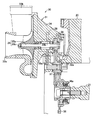
- FIG. 7 is an enlarged sectional view of the compressor and a portion of the engine shown in FIG. 5 .
- FIGS. 1-7 illustrate an embodiment of an engine and assembly having an installation structure for a compressor.
- the embodiments disclosed herein are described in the context of a marine propulsion system of a personal watercraft because these embodiments have particular utility in this context. However, the embodiments and inventions herein can also be applied to other marine vessels, boats, such as small jet boats, as well as other land and marine vehicles. It is to be understood that the embodiments disclosed herein are exemplary but non-limiting embodiments, and thus, the inventions disclosed herein are not limited to the disclosed exemplary embodiments.
- the personal watercraft 10 can have a body 11 that can include a deck 11 a and hull 11 b .
- Steering handlebars (not shown) can be located slightly ahead of the center on the body 11 .
- a seat 12 can also be provided at about the center of an upper part of the body 11 .
- the seat 12 which can be removable from the deck 11 a , can be mounted to an opening 12 a generally at the center of the deck 11 a.
- the inside of the body 11 can be divided into two sections; an engine compartment 13 in the front half of the body 11 , and a pump compartment 14 in the rear half thereof.
- the inside of the body 11 can be a single compartment or it can be divided into additional compartments.
- other configurations can also be used.
- the engine compartment 13 can include an engine 20 , an intake system 15 , and an exhaust system 16 (see FIGS. 2 and 4 ).
- the pump compartment 14 can contain a propulsion unit 17 and other devices.
- air ducts can be provided to introduce or circulate external air into or through the engine compartment 13 .
- These air ducts can extend vertically from the top of the body 11 to the bottom of the engine compartment 13 .
- the air ducts can be designed to take external air from the top end through a waterproof structure (not shown) on the deck 11 a and lead the air from the bottom end into the engine compartment 13 .
- a fuel tank 18 for storing fuel can be provided at the front of the engine compartment 13 .
- the engine 20 can be provided at the bottom center of the body 11 .
- the engine 20 and its surrounding parts can be located below the seat 12 (opening 12 a ), and can be accessed from the outside through the opening 12 a when the seat 12 is removed. As such, the opening 12 a can be provided above the engine 20 in the body 11 of the personal watercraft 10 .
- the engine 20 can be a four-cycle, four-cylinder engine. As shown in FIGS. 5 and 6 , a crankcase 22 can be provided which can contain a crankshaft 21 , as well as a cylinder body 23 and a cylinder head 24 on the crankcase 22 which can form an outer shell of the engine body. The cylinder body 23 and the cylinder head 24 can define a cylinder. The engine 20 can be arranged such that a center axis of the cylinder extends approximately vertically such that it crosses at right angles the crankshaft 21 extending approximately horizontally.
- pistons 26 connected to the crankshaft 21 through connecting rods 25 for up and down movement.
- the up and down motion of the pistons 26 can be transmitted to the crankshaft 21 to produce the rotational motion of the crankshaft 21 .
- Cylinders 27 formed in the cylinder head 24 are each provided with intake and exhaust valves (not shown).
- an inlet port can be in communication with the intake valve of each cylinder 27 and be connected to the intake system 15 , which can include multi-furcated intake pipes 15 a .
- an exhaust port can be in communication with the exhaust valve of each cylinder and be connected to the exhaust system 16 , which can include multi-furcated exhaust pipes 16 a.
- the intake valve can open when taking air in to mix the air from the intake system 15 through the inlet port with the fuel from a fuel supply system (described in greater detail below).
- the air-fuel mixture can be sent to each cylinder 27 for combustion and the intake valve can be closed when the combusted gas is to be discharged.
- the exhaust port can open to allow the combusted gas to be discharged by each cylinder 27 via the exhaust port to the exhaust system 16 . Subsequently, the exhaust port can close at the end of the exhaust stroke of the piston 26 .
- FIGS. 2-4 show an exemplary structure and arrangement of the intake system 15 and the exhaust system 16 when connected to the engine 20 .
- the intake system 15 can have an intake passage that includes the multi-furcated intake pipes 15 a , a surge tank 15 b , and air passages 15 c , 15 d that are in communication with a throttle body (not shown).
- An intercooler 28 can be placed between the air passages 15 c and 15 d .
- a compressor 31 including a supercharger, can be provided at the upstream end of the air passage 15 d .
- An intake box 29 can be provided via an air passage 29 a at the upstream end of the compressor 31 .
- the side from which the gases and liquids are provided can be referred to as the upstream end, while the side to which they are provided can be referred to as the downstream end.
- the intake box 29 can be located in the area on the portside of the body 11 between the engine 20 and fuel tank 18 . In some embodiments, the intake box 29 can be spaced from the engine 20 . Inside of the intake box 29 , an air filter (not shown) can be provided. The intake box 29 can be configured to take the air from the engine compartment 13 , remove foreign substances from the air using the air filter, and then guide the air to the compressor 31 via the air passage 29 a.
- the engine 20 can be formed to include an installation structure 30 .
- the installation structure 30 can have an installation mount 32 .
- the compressor 31 can be provided on an upwardly facing surface 32 a of the installation mount 32 .
- the surface 32 a can be provided in an area across the opening 12 a , for example, facing toward the opening 12 a of the engine compartment 13 .
- the installation mount 32 can protrude forwardly from a front end of the engine 20 .
- the installation mount 32 can extend substantially parallel to the crankshaft 21 of the engine 20 .
- Such a configuration can ease the installation and removal of the compressor 31 for its maintenance.
- the compressor 31 may be easily moved from the opening 12 a toward the surface 32 a of the installation mount 32 , and thereby reduce the required space for installing the compressor 31 .
- the compressor 31 can also be provided with a housing 34 , which can include two vents.
- One of the vents can be an inlet port 33 a , which can be connected to the air passage 29 a and can draw in the air sent from the intake box 29 .
- the other vent can be an outlet port 33 b , which can be connected to the air passage 15 d and can guide the air taken in through the inlet port 33 a to the intercooler 28 .
- the housing 34 can contain a rotary part 35 that can include a drive shaft 35 a and an impeller 35 b .
- the impeller 35 b can be connected to the front end of the drive shaft 35 a in order to be rotatable with the drive shaft 35 a .
- the rotary part 35 can allow the impeller 35 b to be mounted in the housing 34 such that the impeller 35 b extends into the inlet port 33 a.
- the drive shaft 35 a and the crankshaft 21 of the engine 20 can be connected via a directly-coupled gear train.
- the directly-coupled gear train can include at least two gears.
- the directly-coupled gear train can include a drive gear 36 .
- a drive gear 35 c can be installed at the rear end of the drive shaft 35 a .
- the drive gear 36 can be installed at the front end of the crankshaft 21 , and the drive gears 35 c and 36 can be connected via an intermediate gear 37 .
- the compressor 31 can be driven by crankshaft torque, which can be transmitted via the gear train to the drive shaft 35 a and rotary part 35 .
- the transmission of torque to the rotary part 35 can rotate the impeller 35 b .
- the rotation of the impeller 35 b can compress the air from the air passage 29 a to the inlet port 33 a , and then discharge the compressed air from the outlet port 33 b to the air passage 15 d .
- the drive gear 36 of the compressor can be connected to the crankshaft 21 of the engine 20 , such as by direct meshing engagement to the intermediate gear 37 in the directly-coupled gear train, which can transmit driving force to the drive gear 35 c.
- the connection of the compressor 31 to the directly-coupled gear train can ease the installation of the compressor 31 .
- the drive shaft 35 a of the compressor 31 can be connected via the directly-coupled gear train to the crankshaft 21 of the engine 20 , which can prevent time lag of torque transmission and excessive supercharging.
- each of the plurality of gears in the directly-coupled gear train can be smaller in order to save space. This multiplicity can also enable alternative changes of the gears and can change the performance of the compressor itself.
- a torque fluctuation absorbing mechanism can be provided on part of a gear in the directly-coupled gear train, which can be located on the side of the crankcase 22 containing the crankshaft 21 .
- the torque fluctuation absorbing mechanism can be configured to prevent a decrease in engine revolution at a time of sharp deceleration.
- the torque fluctuation mechanism can also be configured to prevent damages to the compressor 31 , for example, by absorbing torque fluctuations which occur during the engine strokes (intake, compression, explosion, and exhaust).
- the drive gear 36 can be provided with a one-way clutch 36 a , which can function as a torque fluctuation absorbing mechanism. If the revolution speed of the crankshaft 21 slows due to deceleration or other reason, the one-way clutch 36 a can idle the drive gear 36 , in order to prevent the compressor 31 from stopping suddenly.
- the one-way clutch 36 can also absorb the torque fluctuations, which occur in the engine strokes (intake, compression, power, and exhaust). The one-way clutch 36 a can thus protect the compressor 31 and the gears in the directly-coupled gear train from being damaged.
- the compressor 31 can be secured on the installation mount 32 with multiple bolts 38 .
- the bolts 38 can be inserted through vertical screw holes 38 a , which can be formed on the installation mount 32 .
- the screw holes 38 a can be oriented perpendicular relative to the surface 32 a of the installation mount 32 , and can be threaded.
- Insertion holes 38 b can also be provided in the housing 34 of the compressor 31 .
- the insertion holes 38 b can be punctured through one to another side of the housing 34 . Accordingly, the installation operation can performed by aligning the compressor 31 on the installation mount 32 and then inserting the bolts 38 through the insertion holes 38 a and into the screw holes 38 a .
- Such a configuration can facilitate the installation operation.
- the compressor 31 can be secured on the surface 32 a of the installation mount 32 by screwing the bolts 38 into the screw holes 38 a after being passed through the insertion holes 38 b .
- the installation structure can enable the drive gear 35 c and intermediate gear 37 to meshingly engage with each other when the compressor is installed on the surface 32 a of the installation mount 32 .
- the intercooler 28 can be provided on the slightly starboard side at the front end of the engine 20 in the body 11 , which can result in juxtaposition with the compressor 31 .
- the intercooler 28 can cool the compressed air from the compressor 31 while it passes through the air passage 15 d.
- the cooling process can increase the density of the compressed air.
- the compressed air can then be sent to the throttle body through the air passage 15 c , illustrated in FIG. 3 .
- the throttle body can include a rotary shaft and a disc-shaped throttle valve (not shown).
- the throttle valve can be attached to the rotary shaft such that the throttle valve can be rotatable with the rotary shaft. In operation, as the rotary shaft rotates, the throttle valve can open and close the air passage inside the throttle body to adjust the amount of air to be provided into each cylinder 27 .
- the surge tank 15 b can be connected to the rear end of the throttle body and can be provided at the top of the starboard side of the engine 20 , as shown in the top plan view of FIG. 3 .
- Four multi-furcated intake pipes 15 a can extend from the side of the surge tank 15 b .
- the intake pipes 15 a can be evenly spaced in the longitudinal direction.
- Each of the multi-furcated intake pipes 15 a can extend obliquely upward from the upstream end, which can be connected to the surge tank 15 b .
- the downstream end can be connected to the inlet port of the cylinder 27 .
- the surge tank 15 b can prevent intake pulsation of the compressed air from the intercooler 28 , and then deliver the compressed air of constant density to the multi-furcated intake pipes 15 a.
- the fuel supply system (not shown) can provide fuel from the fuel tank 18 ( FIG. 1 ) to the engine 20 for combustion therein.
- the fuel supply system can include a fuel pump and a fuel injector.
- the fuel pump can draw fuel from the fuel tank 18 and deliver it to the fuel injector.
- the fuel injector can atomize the fuel into a fine mist, which can then be injected into the cylinder 27 , illustrated in FIG. 6 .
- the fuel can be mixed in the multi-furcated intake pipes 15 a with the compressed air from the inlet box 29 , for example, via the compressor 31 .
- the air-fuel mixture can then be sent into the cylinder 27 .
- an igniter in the engine 20 can activate to ignite the mixture.
- the resulting explosion can move the piston 26 vertically and thereby rotates the crankshaft 21 to generate torque.
- the torque of the crankshaft 21 can then be transmitted to the compressor 31 and propulsion unit 17 .
- the exhaust system 16 can include the multi-furcated exhaust pipes 16 a and an exhaust pipe 16 b .
- the exhaust pipes 16 a can be connected to the exhaust port of each cylinder 27 .
- the exhaust pipe 16 b can be connected with the multiple pipes connected to the downstream end of the multi-furcated exhaust pipes 16 a , a water lock (not shown) connected to the downstream end of the exhaust pipe 16 b , etc.
- the multi-furcated exhaust pipes 16 a can extend obliquely downwardly from the upstream end of the pipes 16 a , which can be connected to the exhaust ports of the cylinders 27 , while the downstream ends of the pipes 16 a can be connected to the exhaust pipe 16 b .
- the exhaust pipe 16 b can extend rearwardly along the lower part of the portside of the engine 20 .
- the downstream end of the exhaust pipe 16 b can be connected to the water lock.
- the water lock can be a cylindrical tank of a large diameter.
- An exhaust gas pipe (not shown) can extend rearwardly from the rear top of the water lock.
- the exhaust gas pipe can extend toward the top and then in the lower rearward direction.
- the downstream end can open to a casing 41 , which can separate the propulsion unit 17 from the main frame of the body 11 .
- the downstream end can also access outside from the rear end of the body 11 .
- a pump drive shaft 42 can be connected to the crankshaft via a coupling 21 a .
- the coupling 21 a can extend into a pump compartment 14 behind the pump drive shaft.
- the pump drive shaft 42 which can be connected to an impeller (not shown) in a jet pump 17 a at the stern of the body 11 , can rotate the impeller by transmitting the torque of the crankshaft 21 driven by the engine 20 .
- the pump drive shaft 42 can be a single shaft member, or it can be made from several separate shafts connected together.
- the propulsion unit 17 which can include the jet pump 17 a , can be placed at about the horizontal center of the rear end of the body 11 .
- the propulsion unit 17 can also include a water inlet 43 open to the bottom of the body 11 and a water nozzle 44 facing toward the end of the stern. Seawater introduced from the water inlet 43 can thus be injected from the water nozzle 44 by operating the jet pump 17 a , which can generate thrust for the body 11 .
- the propulsion unit 17 can be mounted to the bottom of the body 11 at the stern of the body 11 with the casing 41 separating the propulsion unit 17 from the main frame of the body 11 .
- the pump drive shaft 42 can pass through the casing 41 and extend from the engine 20 to the jet pump 17 a of the propulsion unit 17 .
- a steering nozzle 45 can also be provided at the rear end of the jet pump 17 a .
- the steering nozzle 45 can move the rear of the body 11 according to the steering handlebars operation in order to turn the personal watercraft 10 to the right or left.
- the rear of the steering nozzle 45 can also be provided with a reverse gate 46 that can move vertically to advance or reverse the personal watercraft 10 .
- the personal watercraft 10 can be provided with various devices for driving the vehicle. Such devices can include an electric box storing multiple components, a start switch, a variety of sensors, and/or other devices.
- a driver can sit on the seat 12 and turn on the start switch, which can set the personal watercraft 10 in a standby mode.
- the driver can then operate the steering handlebars and a throttle operation element (not shown), which can be provided on the grip of the steering handlebars, to drive the personal watercraft 10 in a certain direction and a speed, as desired.
- the driver When stopping the personal watercraft 10 , the driver can decelerate, stop the vehicle at a pier or dock, and then turn off the start switch. The driver can then open the lid of the opening 12 a after removing the seat 12 from the body 11 , and if necessary, insert their hands inside of the body 11 for maintenance, inspection, and repair of the engine 20 , the compressor 31 , and other parts. In order to inspect the compressor 31 , the bolts 38 can be removed in order to remove the compressor 31 from the installation mount 32 of the engine 20 .
- the opening 12 a can be located on the deck 11 a of the personal watercraft 10 .
- the seat 12 can be removably mountable to the opening 12 a .
- the installation mount 32 for the compressor 31 can be located at the front end of the engine 20 below the opening 12 a .
- the compressor 31 can be installed on the surface 32 a of the installation mount 32 . Due to this structure, the compressor 31 can be installed by carrying the compressor 31 into the body 11 from the opening 12 a , and then lowering the compressor 31 onto the surface 32 a of the installation mount 32 . This can ease the installation of the compressor 31 on the installation mount 32 , and conserve space for installing the compressor 31 . Additionally, such an orientation of the mount 32 can reduce, minimize, and/or eliminate the need to move the compressor 31 parallel to the crankshaft 21 during the installation or removal procedure.
- the bolts 38 can be inserted downward into the insertion holes 38 b on the housing 34 , and tip ends of the bolts 38 can be screwed into the screw holes 38 a of the installation mount 32 to secure the compressor 31 on the installation mount 32 .
- This structure can ease the installation and removal of the compressor 31 to and from the installation mount 32 for maintenance.
- the drive shaft 35 a of the compressor 31 and the crankshaft 21 of the engine 20 can be connected together, for example, by meshing engagement, via the directly-coupled gear train that can include the drive gear 35 c , the intermediate gear 37 and the drive gear 36 . This can prevent excessive supercharging, as well as the time lag of torque transmission from the crankshaft 21 to the compressor 31 .
- the drive gear 36 can be provided with the one-way clutch 36 a .
- the one-way clutch 36 a can absorb the abrupt torque fluctuations along with the decreased engine revolutions at the time of sharp deceleration, thereby preventing the compressor 31 and the gears in the directly-coupled gear train from being damaged.
- the directly-coupled gear train can include the drive gear 35 c , the intermediate gear 37 , and the drive gear 36 .
- Such a structure can enable the gears in the train to be smaller, which can also conserve space. Furthermore, this multiplicity can enable the alternative changes of the gears and easy change in performance of the compressor 31 itself.
- the installation structure 30 can be applied not only to personal watercraft, but to any vehicle that has an engine with a compressor, including automobiles and motorcycles.
- the directly-coupled gear train can include the drive gear 35 c , the intermediate gear 37 , and the drive gear 36 .
- Other configurations can include and/or omit gears.
- the installation mount 32 can be below the opening 12 a in some of the aforementioned embodiments, the locations of the opening and the installation mount can be anywhere, and preferably both the opening and the installation mount face each other.
- the one-way clutch 36 a can be used as a torque fluctuation absorbing mechanism in some of the aforementioned embodiments, a rubber damper can also be used as an alternative.
- the arrangement and structure of the components that form the installation structure can be modified within the technical scope of the inventions described herein.
Abstract
Description
Claims (21)
Applications Claiming Priority (2)
| Application Number | Priority Date | Filing Date | Title |
|---|---|---|---|
| JP2005-277287 | 2005-09-26 | ||
| JP2005277287A JP4614853B2 (en) | 2005-09-26 | 2005-09-26 | Turbocharger mounting structure |
Publications (2)
| Publication Number | Publication Date |
|---|---|
| US20070079796A1 US20070079796A1 (en) | 2007-04-12 |
| US8091534B2 true US8091534B2 (en) | 2012-01-10 |
Family
ID=37910081
Family Applications (1)
| Application Number | Title | Priority Date | Filing Date |
|---|---|---|---|
| US11/527,189 Active 2027-06-18 US8091534B2 (en) | 2005-09-26 | 2006-09-26 | Installation structure for compressor |
Country Status (2)
| Country | Link |
|---|---|
| US (1) | US8091534B2 (en) |
| JP (1) | JP4614853B2 (en) |
Cited By (3)
| Publication number | Priority date | Publication date | Assignee | Title |
|---|---|---|---|---|
| US9909544B2 (en) | 2013-05-17 | 2018-03-06 | Kawasaki Jukogyo Kabushiki Kaisha | Air intake chamber for saddled vehicle |
| US9982592B2 (en) | 2012-09-13 | 2018-05-29 | Kawasaki Jukogyo Kabushiki Kaisha | Supercharger equipped engine |
| US10012139B2 (en) | 2012-09-13 | 2018-07-03 | Kawasaki Jukogyo Kabushiki Kaisha | Engine with supercharger |
Families Citing this family (5)
| Publication number | Priority date | Publication date | Assignee | Title |
|---|---|---|---|---|
| US7654876B1 (en) * | 2005-05-20 | 2010-02-02 | Accessible Technologies, Inc. | Aftermarket supercharger for personal watercraft |
| EP2878787B1 (en) * | 2012-07-11 | 2019-08-21 | Kawasaki Jukogyo Kabushiki Kaisha | Lubrication system for vehicle engine |
| JP6076979B2 (en) * | 2012-07-11 | 2017-02-08 | 川崎重工業株式会社 | Turbocharged engine |
| JP5898775B2 (en) * | 2012-09-13 | 2016-04-06 | 川崎重工業株式会社 | Turbocharged engine |
| JP2018047867A (en) * | 2016-09-23 | 2018-03-29 | ヤマハ発動機株式会社 | Outboard engine unit and ship |
Citations (252)
| Publication number | Priority date | Publication date | Assignee | Title |
|---|---|---|---|---|
| US1871662A (en) | 1929-03-22 | 1932-08-16 | Carrier Engineering Corp | Method and means for lubricating compressors and the like |
| US1876948A (en) | 1927-04-01 | 1932-09-13 | Fairbanks Morse & Co | Lubricant conducting means |
| US1903210A (en) | 1929-02-28 | 1933-03-28 | Carrier Engineering Corp | Sealing and thrust balancing means |
| US1951045A (en) * | 1931-09-22 | 1934-03-13 | Pratt & Whitney Aircraft Compa | Supercharger drive for internal combustion engines |
| US1974974A (en) | 1930-12-01 | 1934-09-25 | Gen Electric | Lubrication of high speed gears and ball bearings |
| US2098718A (en) * | 1933-03-17 | 1937-11-09 | Gen Motors Corp | Supercharger mechanism for internal combustion engines |
| US2151075A (en) | 1937-02-23 | 1939-03-21 | Daimler Benz Ag | Fluid power transmission |
| US2223715A (en) | 1937-03-11 | 1940-12-03 | Daimler Benz Ag | Hydraulic transmission control |
| US2344366A (en) | 1941-03-21 | 1944-03-14 | Lockheed Aircraft Corp | Counterrotating supercharger |
| US2354227A (en) * | 1941-09-23 | 1944-07-25 | Martin Motors Inc | Internal-combustion engine |
| US2366365A (en) | 1942-02-09 | 1945-01-02 | Ford Motor Co | Supercharger |
| US2378452A (en) | 1943-04-19 | 1945-06-19 | Packard Motor Car Co | Internal-combustion engine |
| US2406388A (en) | 1941-06-10 | 1946-08-27 | Gen Electric | Turbosupercharger |
| US2455678A (en) | 1944-02-04 | 1948-12-07 | Irving C Jennings | Power transmission |
| US2523588A (en) | 1948-02-24 | 1950-09-26 | Charles F Ormsby | Screw type oil pump |
| US2565060A (en) | 1947-06-24 | 1951-08-21 | Continental Motors Corp | Transmission mechanism |
| US2695131A (en) * | 1950-12-02 | 1954-11-23 | Besler Corp | Supercharger |
| US2828907A (en) | 1953-10-26 | 1958-04-01 | Mcculloch Motors Corp | High speed friction drive |
| US2847186A (en) | 1953-01-12 | 1958-08-12 | Harvey Machine Co Inc | Fluid driven power unit |
| US2973894A (en) | 1957-06-17 | 1961-03-07 | Turbo Res Corp | Centrifugal compressor for starting jet engines |
| FR1263608A (en) | 1960-07-22 | 1961-06-09 | Sial S A | Device for improving the flow conditions of a gas flow of a periodic nature |
| US3137281A (en) | 1963-07-30 | 1964-06-16 | Joseph A Fulker | Boat engine cooling system |
| US3418986A (en) * | 1965-02-26 | 1968-12-31 | Daimler Benz Ag | Method and apparatus for preventing inlet valve wear of supercharged internal combustion engines |
| US3554322A (en) | 1967-07-26 | 1971-01-12 | Daimler Benz Ag | Internal combustion engine crankcase with dry-sump lubrication |
| US3703877A (en) | 1969-10-17 | 1972-11-28 | Akira Ueda | Water scooter |
| GB1389973A (en) | 1972-03-29 | 1975-04-09 | Ford Motor Co | Rotary screw compressor |
| US3995603A (en) | 1974-04-08 | 1976-12-07 | Hans List | Cooler-cum-blower assembly for internal combustion engines |
| US4010717A (en) | 1975-02-03 | 1977-03-08 | The Bendix Corporation | Fuel control system having an auxiliary circuit for correcting the signals generated by the pressure sensor during transient operating conditions |
| US4035171A (en) | 1976-04-26 | 1977-07-12 | John Zink Company | Gas liquid separator for flare systems |
| US4068612A (en) | 1976-01-26 | 1978-01-17 | M & W Gear Company | Turbocharger housing construction for marine turbocharger and device for turbocharging a marine engine |
| US4198217A (en) | 1977-09-10 | 1980-04-15 | Filterwerk Mann & Hummel Gmbh | Protective air filter intake hood with air deflecting intake screen |
| US4212659A (en) | 1977-12-30 | 1980-07-15 | Fiat Veicoli Industriali S.P.A. | Air-intake devices for internal combustion engines |
| US4267811A (en) | 1978-03-03 | 1981-05-19 | Daimler-Benz Aktiengesellschaft | Cylinder head for a mixture-compressing internal combustion engine |
| US4285632A (en) | 1979-02-28 | 1981-08-25 | United Aircraft Products, Inc. | Oiling system for rotor bearings |
| US4300488A (en) | 1978-07-07 | 1981-11-17 | Autoipari Kutato Intezet | Resonator conduit system for introducing intake gases in internal combustion engines |
| US4319657A (en) | 1978-09-25 | 1982-03-16 | Yamaha Hatsudoki Kabushiki Kaisha | Air intake conduitry for a motorcycle |
| US4321896A (en) | 1979-12-18 | 1982-03-30 | Cummins Engine Company | Gear plate assembly for mounting and positioning an accessory drive train |
| US4326374A (en) | 1980-03-18 | 1982-04-27 | The United States Of America As Represented By The Secretary Of The Navy | High velocity exhaust diffuser and water baffle |
| US4353211A (en) | 1978-12-21 | 1982-10-12 | Autoipari Kutato Intezet | Conduit system for introducing intake gases in internal combustion engines |
| US4412520A (en) | 1980-07-30 | 1983-11-01 | Toyota Jidosha Kogyo Kabushiki Kaisha | Fuel injection control apparatus |
| US4422295A (en) | 1980-10-31 | 1983-12-27 | Yamaha Motor Co., Ltd. | Lubricating system for turbo-chargers |
| US4445337A (en) * | 1982-09-24 | 1984-05-01 | General Motors Corporation | Engine with speed responsive multi-ratio turbocharger drive |
| US4459808A (en) | 1981-02-19 | 1984-07-17 | Ab Volvo | System for controlling the charge air pressure in a turbo-charged combustion engine |
| US4475617A (en) | 1980-09-16 | 1984-10-09 | Yamaha Hatsudoki Kabushiki Kaisha | Engine intake system for motorcycles |
| US4496019A (en) | 1981-06-22 | 1985-01-29 | Yamaha Hatsudoki Kabushiki Kaisha | Offroad auto tricycle |
| US4512152A (en) | 1981-05-09 | 1985-04-23 | Yamaha Hatsudoki Kabushiki Kaisha | Engine with supercharger |
| US4513725A (en) | 1980-08-29 | 1985-04-30 | Yamaha Hatsudoki Kabushiki Kaisha | Device for supplying fuel to a pressure carburetor |
| USRE31877E (en) | 1978-09-25 | 1985-05-07 | Yamaha Hatsudoki Kabushiki Kaisha | Air intake conduitry for a motorcycle |
| US4519373A (en) | 1982-09-30 | 1985-05-28 | The Garrett Corporation | Internal combustion engine having a variably engagable slipping wet clutch for driving a supercharger |
| US4538556A (en) | 1983-07-11 | 1985-09-03 | Toyota Jidosha Kabushiki Kaisha | Air intake device of an internal combustion engine |
| US4553515A (en) | 1983-10-22 | 1985-11-19 | Bl Technology Limited | Cylinder head for spark ignition internal combustion engine |
| US4562697A (en) | 1984-12-10 | 1986-01-07 | Merlin Marine Engine Corp. | Intercooler for turbocharged internal combustion engine |
| US4630446A (en) | 1983-05-27 | 1986-12-23 | Sanshin Kogyo Kabushiki Kaisha | Outboard motor with turbo-charger |
| US4633826A (en) | 1980-02-21 | 1987-01-06 | Yamaha Hatsudoki Kabushiki Kaisha | Overhead cam shaft type V-engine cylinder block |
| US4662323A (en) | 1984-05-01 | 1987-05-05 | Honda Giken Kogyo Kabushiki Kaisha | Overhead cam type valve actuating apparatus for internal combustion engine |
| US4674457A (en) | 1986-06-02 | 1987-06-23 | Ford Motor Company | Dry sump crankcase |
| US4678441A (en) | 1985-01-24 | 1987-07-07 | Kawasaki Jukogyo Kabushiki Kaisha | System for discharging water from crank chamber |
| US4702219A (en) | 1984-08-29 | 1987-10-27 | Mazda Motor Corporation | Supercharged engine |
| US4709682A (en) | 1985-12-03 | 1987-12-01 | Toyota Jidosha Kabushiki Kaisha | Device for controlling the pressure in the bearings of a roots blower supercharger |
| US4712517A (en) | 1984-12-13 | 1987-12-15 | Honda Giken Kogyo Kabushiki Kaisha | Cylinder block structure for multicylinder internal combustion engines |
| US4718396A (en) | 1985-10-21 | 1988-01-12 | Honda Giken Kogyo Kabushiki Kaisha | Multicylinder internal combustion engine with rotation sensor |
| US4723526A (en) | 1985-03-19 | 1988-02-09 | Yamaha Hatsudoki Kabushiki Kaisha | Drive arrangement for supercharger |
| US4733361A (en) | 1980-09-03 | 1988-03-22 | Krieser Uri R | Life usage indicator |
| US4738229A (en) | 1984-12-10 | 1988-04-19 | Toyota Jidosha Kabushiki Kaisha | Internal combustion engine air intake system with variable effective length |
| US4741302A (en) | 1984-12-10 | 1988-05-03 | Mazda Motor Corporation | Internal combustion engine |
| US4760703A (en) | 1980-10-25 | 1988-08-02 | Yamaha Hatsudoki Kabushiki Kaisha | Induction system for internal combustion engines |
| US4781553A (en) | 1987-07-24 | 1988-11-01 | Kabushiki Kaisha Kobe Seiko Sho | Screw vacuum pump with lubricated bearings and a plurality of shaft sealing means |
| US4796574A (en) | 1986-07-09 | 1989-01-10 | Honda Giken Kogyo Kabushiki Kaisha | SOHC type internal combustion engine |
| US4797068A (en) | 1986-06-12 | 1989-01-10 | Hitachi, Ltd. | Vacuum evacuation system |
| US4827722A (en) | 1985-06-05 | 1989-05-09 | Sanshin Kogyo Kabushiki Kaisha | Engine with turbo-charger for an outboard motor |
| US4848170A (en) | 1986-11-19 | 1989-07-18 | Honda Giken Kogyo Kabushiki Kaisha | Starting apparatus for an internal combustion engine |
| US4887692A (en) | 1987-04-13 | 1989-12-19 | Sanshin Kogyo Kabushiki Kaisha | Noise reducing device for marine propulsion |
| US4896734A (en) | 1985-03-27 | 1990-01-30 | Yamaha Hatsudoki Kabushiki Kaisha | Supercharged motor vehicle |
| US4900343A (en) | 1980-10-25 | 1990-02-13 | Yamaha Hatsudoki Kabushiki Kaisha | Induction system for internal combustion engines |
| US4936278A (en) | 1988-09-22 | 1990-06-26 | Honda Giken Kogyo K.K. | Air-fuel ratio control method for internal combustion engines |
| US4938664A (en) | 1989-11-13 | 1990-07-03 | Carrier Corporation | Oil reclaim system |
| US4955352A (en) | 1986-02-26 | 1990-09-11 | Aisin Seiki Kabushiki Kaisha | Combined supercharger and supercharger coolant pump for an internal combustion engine |
| US4972807A (en) | 1988-05-30 | 1990-11-27 | Yamaha Hatsudoki Kabushiki Kaisha | Cylinder head cooling for multiple valve engine |
| US4982682A (en) | 1988-09-08 | 1991-01-08 | Yamaha Hatsudoki Kabushiki Kaisha | Hull construction for small watercraft |
| US4984974A (en) | 1987-12-18 | 1991-01-15 | Hitachi, Ltd. | Screw type vacuum pump with introduced inert gas |
| US4984528A (en) | 1988-11-28 | 1991-01-15 | Yamaha Hatsudoki Kabushiki Kaisha | Venting and drain arrangement for small watercraft |
| US4989409A (en) | 1988-09-22 | 1991-02-05 | Sanshin Kogyo Kabushiki Kaisha | Exhaust device for small sized boat engine |
| US4991532A (en) | 1989-06-02 | 1991-02-12 | Boat Safe Products, Inc. | Automatic control of engine compartment ventilation |
| US5002021A (en) | 1989-01-24 | 1991-03-26 | Mazda Motor Corporation | Intake system for multiple cylinder engine |
| US5009204A (en) | 1988-11-30 | 1991-04-23 | Fuji Jukogyo Kabushiki Kaisha | Spark plug arrangement in an overhead camshaft engine |
| US5014816A (en) | 1989-11-09 | 1991-05-14 | E. I. Du Pont De Nemours And Company | Silencer for gas induction and exhaust systems |
| US5031591A (en) | 1989-01-30 | 1991-07-16 | Honda Giken Kogyo Kabushiki Kaisha | OHC vertical crankshaft engine |
| US5060622A (en) * | 1988-02-18 | 1991-10-29 | Yamaha Hatsudoki Kabushiki Kaisha | Supercharged motor vehicle |
| US5088280A (en) | 1988-03-23 | 1992-02-18 | Rolls-Royce Plc | Prevention of icing in the intakes of aerospace propulsors |
| US5094193A (en) | 1989-08-23 | 1992-03-10 | Yamaha Hatsudoki Kabushiki Kaisha | Cylinder head cooling arrangement |
| US5095859A (en) | 1990-04-13 | 1992-03-17 | Honda Giken Kogyo Kabushiki Kaisha | Sohc type internal combustion engine |
| US5119795A (en) | 1991-01-30 | 1992-06-09 | Mazda Motor Corporation | Intake system with mechanical supercharger for internal combustion engine |
| US5130014A (en) | 1989-11-30 | 1992-07-14 | General Motors Corporation | Removable sump oil pan for an internal combustion engine |
| US5133307A (en) | 1989-11-08 | 1992-07-28 | Sanshin Kogyo Kabushiki Kaisha | Air intake system for marine propulsion unit engine |
| US5136547A (en) | 1989-03-16 | 1992-08-04 | Laukien Guenther | Method and apparatus for reducing for reducing acoustic emission from submerged submarines |
| US5136993A (en) | 1990-01-19 | 1992-08-11 | Dr. Ing. H.C.F. Porsche Ag | Internal-combustion engine oil guiding housing |
| US5143028A (en) | 1989-12-11 | 1992-09-01 | Sanshin Kogyo Kabushiki Kaisha | Supercharged V type two cycle engine |
| US5158427A (en) | 1990-06-15 | 1992-10-27 | Aisin Seiki Kabushiki Kaisha | Centrifugal supercharger |
| US5159903A (en) | 1989-12-06 | 1992-11-03 | Sanshin Kogyo Kabushiki Kaisha | Air intake system for two cycle multi cylinder engine |
| US5163811A (en) | 1988-07-25 | 1992-11-17 | Isuzu Motors Limited | Brake mechanism for vehicles |
| USRE34226E (en) | 1988-05-30 | 1993-04-20 | Yamaha Hatsudoki Kabushiki Kaisha | Cylinder head cooling for multiple valve engine |
| US5215164A (en) | 1989-04-20 | 1993-06-01 | Sanshin Kogyo Kabushiki Kaisha | Lubricating device for four stroke outboard motor |
| US5230320A (en) | 1991-06-27 | 1993-07-27 | Mazda Motor Corporation | Intake and exhaust control system for automobile engine |
| US5239950A (en) | 1991-11-02 | 1993-08-31 | Sanshin Kogyo Kabushiki Kaisha | 2-cycle engine |
| US5243945A (en) | 1991-04-22 | 1993-09-14 | Sanshin Kogyo Kabushiki Kaisha | Fuel injection system for the internal combustion engine |
| US5253618A (en) | 1991-11-16 | 1993-10-19 | Sanshin Kogyo Kabbushiki Kaisha | Marine engine |
| US5261356A (en) | 1991-11-16 | 1993-11-16 | Sanshin Kogyo Kabushiki Kaisha | Outboard motor |
| US5293846A (en) | 1989-12-11 | 1994-03-15 | Sanshin Kogyo Kabushiki Kaisha | Two-cycle engine for an outboard motor |
| US5299423A (en) | 1991-04-08 | 1994-04-05 | Yamaha Hatsudoki Kabushiki Kaisha | Air supply system for supercharged internal combustion engine |
| US5330374A (en) | 1992-02-17 | 1994-07-19 | Sanshin Kogyo Kabushiki Kaisha | Jet propulsion system |
| US5334063A (en) | 1992-04-02 | 1994-08-02 | Sanshin Kogyo Kabushiki Kaisha | Cooling system for marine propulsion engine |
| US5340344A (en) | 1992-04-30 | 1994-08-23 | Sanshin Kogyo Kabushiki Kaisha | Air intake system |
| US5340343A (en) | 1992-04-14 | 1994-08-23 | Sanshin Kogyo Kabushiki Kaisha | Marine propulsion unit |
| US5357913A (en) | 1992-04-10 | 1994-10-25 | Sanshin Kogyo Kabushiki Kaisha | Flame arrester arrangement for marine propulsion engine |
| US5365908A (en) | 1991-10-15 | 1994-11-22 | Yamaha Hatsudoki Kabushiki Kaisha | Burning control system for engine |
| US5377634A (en) | 1992-09-08 | 1995-01-03 | Yamaha Hatsudoki Kabushiki Kaisha | Compressor system for reciprocating machine |
| US5377629A (en) | 1993-10-20 | 1995-01-03 | Siemens Electric Limited | Adaptive manifold tuning |
| US5389022A (en) | 1989-11-21 | 1995-02-14 | Yamaha Hatsudoki Kabushiki Kaisha | Jet boat |
| US5390621A (en) | 1991-11-01 | 1995-02-21 | Yamaha Hatsudoki Kabushiki Kaisha | Watercraft |
| USRE34922E (en) | 1991-10-09 | 1995-05-02 | Yamaha Hatsudoki Kabushiki Kaisha | Watercraft |
| US5427079A (en) | 1992-12-04 | 1995-06-27 | Ford Motor Company | Supercharged engine with variable ratio drive supercharger |
| US5438946A (en) | 1993-03-23 | 1995-08-08 | Yamaha Hatsudoki Kabushiki Kaisha | Personal jet propelled watercraft |
| US5456230A (en) | 1994-05-19 | 1995-10-10 | Outboard Marine Corporation | Four-stroke internal combustion engine with contaminated oil elimination |
| US5476402A (en) | 1993-03-15 | 1995-12-19 | Sanshin Kogyo Kabushiki Kaisha | Intake and exhaust structure for V-type engine |
| US5477838A (en) | 1989-02-27 | 1995-12-26 | Orbital Engine Company (Australia) Pty Limited | Supercharged engines |
| US5503117A (en) | 1993-10-29 | 1996-04-02 | Yamaha Hatsudoki Kabushiki Kaisha | Engine cooling system |
| US5513606A (en) | 1993-04-15 | 1996-05-07 | Sanshin Kogyo Kabushiki Kaisha | Marine propulsion unit |
| US5529027A (en) | 1993-10-12 | 1996-06-25 | Yamaha Hatsudoki Kabushiki Kaisha | Liquid-cooled internal combustion engine |
| US5537968A (en) | 1994-01-11 | 1996-07-23 | Sanshin Kogyo Kabushiki Kaisha | Balancer shaft arrangement for four-cycle watercraft engine |
| US5558549A (en) | 1994-02-28 | 1996-09-24 | Sanshin Kogyo Kabushiki Kaisha | Four cycle engine for watercraft |
| US5586922A (en) | 1991-12-28 | 1996-12-24 | Yamaha Hatsudoki Kabushiki Kaisha | Watercraft |
| EP0500139B1 (en) | 1991-02-22 | 1997-01-29 | Yamaha Hatsudoki Kabushiki Kaisha | Induction system for a multiple valve internal combustion engine |
| US5603301A (en) | 1994-07-07 | 1997-02-18 | Yamaha Hatsudoki Kabushiki Kaisha | Fuel-injected engine |
| US5619950A (en) | 1993-04-27 | 1997-04-15 | Yamaha Hatsudoki Kabushiki Kaisha | Watercraft |
| US5632239A (en) | 1996-04-16 | 1997-05-27 | Chrysler Corporation | Method of distributing air in an engine intake manifold |
| US5634422A (en) | 1993-02-15 | 1997-06-03 | Yamah Ahatsudoki Kabushiki Kaisha | Personal watercraft with V-type engine |
| US5636586A (en) | 1992-11-16 | 1997-06-10 | Sanshin Kogyo Kabushiki Kaisha | Watercraft bilge system |
| US5638796A (en) | 1994-06-03 | 1997-06-17 | Adams, Iii; Herbert L. | Electric supercharger |
| US5647779A (en) | 1995-07-19 | 1997-07-15 | Sanshin Kogyo Kabushiki Kaisha | Manifold and water trap system for marine engine |
| US5660571A (en) | 1992-07-24 | 1997-08-26 | Sanshin Kogyo Kabushiki Kaisha | Muffling device for outboard propulsion machine |
| US5660115A (en) | 1995-10-27 | 1997-08-26 | Harsco Corporation | Vertically actuated rail guide wheels |
| US5664515A (en) | 1994-11-09 | 1997-09-09 | Yamaha Hatsudoki Kabushiki Kaisha | Ventilating arrangement for watercraft |
| US5671703A (en) | 1995-09-18 | 1997-09-30 | Yamaha Matsudoki Kabushiki Kaisha | Two-cycle engine |
| US5678525A (en) | 1995-11-24 | 1997-10-21 | Yamaha Hatsudoki Kabushiki Kaisha | Fuel supply device for crankcase chamber supercharged engine |
| US5682870A (en) | 1994-12-28 | 1997-11-04 | Yamaha Hatsudoki Kabushiki Kaisha | Air fuel ratio detecting device and system for engines |
| US5699749A (en) | 1994-10-21 | 1997-12-23 | Yamaha Hatsudoki Kabushiki Kaisha | Exhaust system, hull, and speed indicator for watercraft |
| US5709186A (en) | 1995-11-24 | 1998-01-20 | Yamaha Hatsudoki Kabushiki Kaisha | Lubrication device for crank chamber supercharged engine |
| US5709198A (en) | 1995-03-31 | 1998-01-20 | Nippondenso Co., Ltd. | Oxygen concentration detecting apparatus |
| US5709185A (en) | 1994-11-29 | 1998-01-20 | Ishikawajima-Shibaura Machinery Co., Ltd. | Lubricating system for four-stroke-cycle engine |
| US5743206A (en) | 1996-02-14 | 1998-04-28 | Yamaha Hatsudoki Kabushiki Kaisha | Hull for small watercraft |
| US5746270A (en) | 1996-01-30 | 1998-05-05 | Brunswick Corporation | Heat exchanger for marine engine cooling system |
| US5755194A (en) | 1995-07-06 | 1998-05-26 | Tecumseh Products Company | Overhead cam engine with dry sump lubrication system |
| US5755283A (en) | 1995-12-08 | 1998-05-26 | Gas Reasearch Institute | Combined thermostat and selector valve arrangement for gas driven heat pump systems |
| US5769039A (en) | 1996-06-04 | 1998-06-23 | Yamaha Hatsudoki Kabushiki Kaisha | V shaped multi-cylinder engine of crankcase compression type |
| US5778838A (en) | 1995-11-29 | 1998-07-14 | Yamaha Hatsudoki Kabushiki Kaisha | Fuel supply device for crankcase chamber supercharged engine |
| US5778857A (en) | 1995-10-02 | 1998-07-14 | Yamaha Hatsudoki Kabushiki Kaisha | Engine control system and method |
| US5779451A (en) | 1995-06-05 | 1998-07-14 | Hatton; Gregory John | Power efficient multi-stage twin screw pump |
| US5778833A (en) | 1996-06-06 | 1998-07-14 | Yamaha Hatsudoki Kabushiki Kaisha | Water vehicle having a "V" shaped multi-cylinder crankcase scavenging engine |
| US5797778A (en) | 1996-01-30 | 1998-08-25 | Yamaha Hatsudoki Kabushiki Kaisha | Mounting arrangement for marine propulsion engine |
| US5813888A (en) | 1994-04-21 | 1998-09-29 | Sanshin Kogyo Kabushiki Kaisha | System for flushing a watercraft engine cooling system |
| US5820426A (en) | 1997-02-21 | 1998-10-13 | Brunswick Corporation | Exhaust system for personal watercraft |
| US5827096A (en) | 1996-04-18 | 1998-10-27 | Yamaha Hatsudoki Kabushiki Kaisha | Watercraft exhaust control |
| US5829402A (en) | 1995-09-29 | 1998-11-03 | Sanshin Kogyo Kabushiki Kaisha | Induction system for engine |
| US5830021A (en) | 1995-12-30 | 1998-11-03 | Sanshin Kogyo Kabushiki Kaisha | Outboard motor engine arrangement |
| US5839930A (en) | 1996-03-15 | 1998-11-24 | Yamaha Hatsudoki Kabushiki Kaisha | Engine lubricating system for watercraft |
| US5846102A (en) | 1996-09-11 | 1998-12-08 | Kawasaki Jukogyo Kabushiki Kaisha | Four-cycle engine for a small jet boat |
| US5845618A (en) | 1996-04-23 | 1998-12-08 | Yamaha Hatsudoki Kabushiki Kaisha | Engine for transport vehicle |
| US5855193A (en) | 1996-08-26 | 1999-01-05 | Sanshin Kogyo Kabushiki Kaisha | Induction system for outboard motor |
| US5871380A (en) | 1997-09-12 | 1999-02-16 | Claussen; Dean | Intercooler for the stern drive of a boat |
| US5871340A (en) | 1995-06-05 | 1999-02-16 | Hatton; Gregory John | Apparatus for cooling high-pressure boost high gas-fraction twin-screw pumps |
| US5899778A (en) | 1996-04-12 | 1999-05-04 | Sanshin Kogyo Kabushiki Kaisha | Outboard motor induction system |
| US5902161A (en) | 1997-05-21 | 1999-05-11 | Yamaha Hatsudoki Kabushiki Kaisha | Air temperature sensor arrangement for a small watercraft |
| US5906083A (en) | 1997-08-04 | 1999-05-25 | Construction Specialties, Inc. | Modular louver system |
| US5908337A (en) | 1996-08-30 | 1999-06-01 | Yamaha Hatsudoki Kabushiki Kaisha | Air intake for personal watercraft engine |
| US5911211A (en) | 1995-12-28 | 1999-06-15 | Yamaha Hatsudoki Kabushiki Kaisha | Supercharged engine |
| US5928044A (en) | 1996-10-02 | 1999-07-27 | Yamaha Hatsudoki Kabushiki Kaisha | Exhaust system for an engine |
| US5934070A (en) | 1996-06-28 | 1999-08-10 | Daimler-Benz A.G. | Exhaust gas turbocharger and exhaust gas manifold arrangement on an internal combustion engine |
| US5937825A (en) | 1997-10-09 | 1999-08-17 | Sanshin Kogyo Kabushiki Kaisha | Engine control system and method |
| US5937818A (en) | 1996-12-20 | 1999-08-17 | Sanshin Kogyo Kabushiki Kaisha | Ventilation system for outboard motor |
| US5941223A (en) | 1995-09-20 | 1999-08-24 | Sanshin Kogyo Kabushiki Kaisha | Engine control system and method |
| US5957112A (en) | 1996-04-12 | 1999-09-28 | Sanshin Kogyo Kabushiki Kaisha | Injector arrangement for engine |
| US5957072A (en) | 1996-08-29 | 1999-09-28 | Yamaha Hatsudoki Kabushiki Kaisha | Air-intake system for watercraft |
| US5960770A (en) | 1996-04-02 | 1999-10-05 | Yamaha Hatsudoki Kabushiki Kaisha | Multi-cylinder engine of crankcase scavenging type for watercraft |
| US5983878A (en) | 1996-07-08 | 1999-11-16 | Sanshin Kogyo Kabushiki Kaisha | Engine control |
| US6006540A (en) | 1998-08-03 | 1999-12-28 | Ford Global Technologies, Inc. | Charge air management system for automotive engine |
| US6009705A (en) | 1995-11-06 | 2000-01-04 | Tennex Europe Limited | Noise attenuator for an induction system or an exhaust system |
| US6015321A (en) | 1996-12-28 | 2000-01-18 | Yamaha Hatsudoki Kabushiki Kaisha | Fuel pump mounting arrangement for personal watercraft |
| US6015320A (en) | 1996-05-31 | 2000-01-18 | Yamaha Hatsudoki Kabushiki Kaisha | Oil cooler for watercraft |
| US6016782A (en) | 1997-03-07 | 2000-01-25 | Yamaha Hatsudoki Kabushiki Kaisha | Accelerating pump for watercraft engine |
| US6022252A (en) | 1997-03-13 | 2000-02-08 | Yamaha Hatsudoki Kabushiki Kaisha | Breather arrangement for watercraft engine |
| US6026775A (en) | 1997-01-31 | 2000-02-22 | Suzuki Motor Corporation | Intake system of engine |
| US6029638A (en) | 1997-11-07 | 2000-02-29 | Honda Giken Kogyo Kabushiki Kaisha | Internal combustion engine with dry sump lubricating system |
| US6041758A (en) | 1998-06-19 | 2000-03-28 | Mitsubishi Denki Kabushiki Kaisha | Fuel injection amount controller for engines |
| US6055959A (en) | 1997-10-03 | 2000-05-02 | Yamaha Hatsudoki Kabushiki Kaisha | Engine supercharged in crankcase chamber |
| US6079378A (en) | 1995-09-01 | 2000-06-27 | Yamaha Hatsudoki Kabushiki Kaisha | Suction device for a supercharged engine |
| US6085702A (en) | 1997-03-21 | 2000-07-11 | Yamaha Hatsudoki Kabushiki Kaisha | Lubrication system for an engine having a floatless carburetor |
| US6099371A (en) | 1997-03-21 | 2000-08-08 | Sanshin Kogyo Kabushiki Kaisha | Cowling for outboard motor |
| US6142842A (en) | 1997-09-12 | 2000-11-07 | Sanshin Kogyo Kabushiki Kaisha | Manifold arrangement for outboard motor |
| US6149477A (en) | 1998-11-12 | 2000-11-21 | Suzuki Motor Corporation | Air intake device for an outboard motor |
| US6171380B1 (en) | 1999-03-12 | 2001-01-09 | Carrier Corporation | Microprocessor cooler with integral acoustic attenuator |
| US6192871B1 (en) * | 1998-10-30 | 2001-02-27 | Vortech Engineering, Inc. | Compact supercharger |
| US6205987B1 (en) | 1997-12-25 | 2001-03-27 | Honda Giken Kogyo Kabushiki Kaisha | Small-sized boat |
| US6213062B1 (en) | 1998-08-31 | 2001-04-10 | Suzuki Motor Corporation | Cooling system for engine with supercharger |
| US6263851B1 (en) | 1997-03-07 | 2001-07-24 | Yamaha Hatsudoki Kabushiki Kaisha | Air inlet device for watercraft engine |
| US6269797B1 (en) | 1997-11-19 | 2001-08-07 | Yamaha Hatsudoki Kabushiki Kaisha | Cylinder head and manifold arrangement for injected engine |
| US6279372B1 (en) | 1998-09-16 | 2001-08-28 | Siemens Aktiengesellschaft | Method of correcting the characteristic curve of a linear lambda probe |
| US6286492B1 (en) | 1999-03-25 | 2001-09-11 | Sanshin Kogyo Kabushiki Kaisha | Fuel injection control |
| US6302752B1 (en) | 1998-07-29 | 2001-10-16 | Yamaha Hatsudoki Kabushiki Kaisha | Induction system for watercraft engine |
| US6312299B1 (en) | 1998-12-10 | 2001-11-06 | Yamaha Hatsudoki Kabushiki Kaisha | Induction system for watercraft engine |
| US6318085B1 (en) | 1997-03-27 | 2001-11-20 | Robert Bosch Gmbh | Ambient air-pulsed valve control |
| US20010044352A1 (en) | 2000-02-29 | 2001-11-22 | Norbert Korenjak | Control tensioner device for an engine |
| US20020025742A1 (en) | 2000-08-24 | 2002-02-28 | Yves Berthiaume | Vehicle having improved fuel, lubrication and air intake systems |
| US6394060B2 (en) | 2000-01-21 | 2002-05-28 | Kioritz Corporation | Lubricating method and device of internal combustion engine |
| US6394777B2 (en) | 2000-01-07 | 2002-05-28 | The Nash Engineering Company | Cooling gas in a rotary screw type pump |
| US6447351B1 (en) | 1999-06-17 | 2002-09-10 | Yamaha Hatsudoki Kabushiki Kaisha | Vapor system arrangement for marine engine |
| US6453890B1 (en) | 1999-09-09 | 2002-09-24 | Yamaha Hatsudoki Kabushiki Kaisha | Supercharged engine |
| US20030015126A1 (en) | 2001-07-17 | 2003-01-23 | Yoshitsugu Gokan | Personal watercraft on which supercharger is mounted |
| US6516789B1 (en) * | 2000-09-22 | 2003-02-11 | Accessible Technologies, Inc. | Centrifugal supercharger having lubricating slinger |
| US6517397B1 (en) | 1999-09-24 | 2003-02-11 | Sanshin Kogyo Kabushiki Kaisha | Air induction system for small watercraft |
| US20030094162A1 (en) * | 2001-11-19 | 2003-05-22 | Baldwin Steven R. | Engine air-assisted injection compressor drive |
| US6578508B2 (en) | 2001-02-15 | 2003-06-17 | Yamaha Hatsudoki Kabushiki Kaisha | Small watercraft hull and engine arrangement |
| US6623321B2 (en) | 1999-12-09 | 2003-09-23 | Yamaha Marine Kabushiki Kaisha | Air induction system for small watercraft |
| US6637406B2 (en) | 2000-08-02 | 2003-10-28 | Yamaha Hatsudoki Kabushiki Kaisha | In-cylinder injection engine with supercharger |
| US6640754B1 (en) | 2000-09-14 | 2003-11-04 | Yamaha Hatsudoki Kabushiki Kaisha | Ignition timing system for homogeneous charge compression engine |
| US6644942B2 (en) | 2000-07-18 | 2003-11-11 | Alcatel | Monobloc housing for vacuum pump |
| US6651633B1 (en) * | 2000-11-03 | 2003-11-25 | Accessible Technologies, Inc. | Centrifugal compressor having compound bearing assembly |
| US6663366B2 (en) | 2001-05-16 | 2003-12-16 | Denso Corporation | Compressor having cooling passage integrally formed therein |
| US6672919B1 (en) | 2002-10-09 | 2004-01-06 | Thomas William Beson | Temperature control system for marine exhaust |
| US6672918B2 (en) | 2000-01-17 | 2004-01-06 | Yamaha Marine Kabushiki Kaisha | Induction system for 4-cycle engine of small watercraft |
| US6746288B2 (en) | 2001-07-13 | 2004-06-08 | Honda Giken Kogyo Kabushiki Kaisha | Personal watercraft having internal combustion engine with supercharger incorporated therein |
| US6769942B2 (en) | 2000-08-11 | 2004-08-03 | Bombardier Recreational Products Inc. | Watercraft having air/water separating device |
| US6793546B2 (en) | 2002-03-04 | 2004-09-21 | Kawasaki Jukogyo Kabushiki Kaisha | Small watercraft |
| US6796126B2 (en) | 2001-12-27 | 2004-09-28 | Hks Co. Ltd. | Supercharger |
| US6810855B2 (en) | 2001-07-12 | 2004-11-02 | Yamaha Hatsudoki Kabushiki Kaisha | 4-Stroke engine control device and control method |
| US20040253886A1 (en) | 2003-06-12 | 2004-12-16 | Tetsuya Mashiko | Intake manifold for small watercraft |
| US6896566B2 (en) | 2001-12-21 | 2005-05-24 | Kawasaki Jukogyo Kabushiki Kaisha | Personal watercraft |
| US20050172919A1 (en) | 2004-02-09 | 2005-08-11 | Atsufumi Ozaki | Water-jet propulsion personal watercraft |
| US6935102B2 (en) | 2000-04-19 | 2005-08-30 | Sandvik Ab | Method of controlling the concentration of nitrogen oxides, hydrocarbons and carbon monoxide in conjunction with the cleansing of emission gases |
| US20050204730A1 (en) * | 2004-03-16 | 2005-09-22 | Kojyu Tsukahara | Engine with a charging system |
| US20050247498A1 (en) | 2002-08-13 | 2005-11-10 | Bombardier-Rotax Gmbh & Co. Kg | Engine arrangement for a snowmobile |
| US20050268878A1 (en) * | 2002-01-11 | 2005-12-08 | Kazumasa Ito | Viscoidal fluid removing arrangement for engine |
| US6973985B2 (en) | 2003-03-28 | 2005-12-13 | Suzuki Motor Corporation | Snow vehicle |
| US20050279335A1 (en) * | 2004-06-16 | 2005-12-22 | Shigeyuki Ozawa | Water jet propulsion boat |
| US20050279092A1 (en) * | 2004-06-16 | 2005-12-22 | Shigeyuki Ozawa | Water jet propulsion boat |
| US20060016437A1 (en) * | 2004-07-22 | 2006-01-26 | Shigeyuki Ozawa | Intake system for supercharged engine |
| US7007682B2 (en) | 2001-06-28 | 2006-03-07 | Yamaha Hatsudoki Kabushiki Kaisha | Blow-by gas separator |
| US20060054146A1 (en) | 2004-09-10 | 2006-03-16 | Shigeyuki Ozawa | Supercharger lubrication structure |
| US20060060170A1 (en) | 2004-09-14 | 2006-03-23 | Shigeyuki Ozawa | Supercharger lubrication structure |
| US20060243259A1 (en) | 2005-04-28 | 2006-11-02 | Hks Co., Ltd. | Supercharger |
| US20070059997A1 (en) | 2005-08-29 | 2007-03-15 | Shigeharu Mineo | Small planing boat |
| US20070062498A1 (en) * | 2005-09-21 | 2007-03-22 | Woods Terrill W | Supercharger gear drive system |
| US7607958B1 (en) * | 2006-03-09 | 2009-10-27 | Brp-Powertrain Gmbh & Co Kg | Marine engine |
Family Cites Families (7)
| Publication number | Priority date | Publication date | Assignee | Title |
|---|---|---|---|---|
| JPH026289A (en) * | 1988-06-23 | 1990-01-10 | Yamaha Motor Co Ltd | Motorcycle having engine with supercharger |
| US5212659A (en) * | 1991-10-08 | 1993-05-18 | Crystal Semiconductor | Low precision finite impulse response filter for digital interpolation |
| JPH084545A (en) * | 1994-06-21 | 1996-01-09 | Tochigi Fuji Ind Co Ltd | Centrifugal supercharger |
| JP2759789B2 (en) * | 1996-06-03 | 1998-05-28 | 川崎重工業株式会社 | Small planing boat internal combustion engine |
| JP2001289051A (en) * | 2000-04-03 | 2001-10-19 | Ishikawajima Harima Heavy Ind Co Ltd | Device and method for preventing tooth hitting sound of mechanical supercharger |
| US6672929B2 (en) * | 2002-05-01 | 2004-01-06 | Lisa Leleu | Puppet system |
| JP2004148917A (en) * | 2002-10-29 | 2004-05-27 | Kawasaki Heavy Ind Ltd | Small-sized running motorboat |
-
2005
- 2005-09-26 JP JP2005277287A patent/JP4614853B2/en active Active
-
2006
- 2006-09-26 US US11/527,189 patent/US8091534B2/en active Active
Patent Citations (267)
| Publication number | Priority date | Publication date | Assignee | Title |
|---|---|---|---|---|
| US1876948A (en) | 1927-04-01 | 1932-09-13 | Fairbanks Morse & Co | Lubricant conducting means |
| US1903210A (en) | 1929-02-28 | 1933-03-28 | Carrier Engineering Corp | Sealing and thrust balancing means |
| US1871662A (en) | 1929-03-22 | 1932-08-16 | Carrier Engineering Corp | Method and means for lubricating compressors and the like |
| US1974974A (en) | 1930-12-01 | 1934-09-25 | Gen Electric | Lubrication of high speed gears and ball bearings |
| US1951045A (en) * | 1931-09-22 | 1934-03-13 | Pratt & Whitney Aircraft Compa | Supercharger drive for internal combustion engines |
| US2098718A (en) * | 1933-03-17 | 1937-11-09 | Gen Motors Corp | Supercharger mechanism for internal combustion engines |
| US2151075A (en) | 1937-02-23 | 1939-03-21 | Daimler Benz Ag | Fluid power transmission |
| US2223715A (en) | 1937-03-11 | 1940-12-03 | Daimler Benz Ag | Hydraulic transmission control |
| US2344366A (en) | 1941-03-21 | 1944-03-14 | Lockheed Aircraft Corp | Counterrotating supercharger |
| US2406388A (en) | 1941-06-10 | 1946-08-27 | Gen Electric | Turbosupercharger |
| US2354227A (en) * | 1941-09-23 | 1944-07-25 | Martin Motors Inc | Internal-combustion engine |
| US2366365A (en) | 1942-02-09 | 1945-01-02 | Ford Motor Co | Supercharger |
| US2378452A (en) | 1943-04-19 | 1945-06-19 | Packard Motor Car Co | Internal-combustion engine |
| US2455678A (en) | 1944-02-04 | 1948-12-07 | Irving C Jennings | Power transmission |
| US2565060A (en) | 1947-06-24 | 1951-08-21 | Continental Motors Corp | Transmission mechanism |
| US2523588A (en) | 1948-02-24 | 1950-09-26 | Charles F Ormsby | Screw type oil pump |
| US2695131A (en) * | 1950-12-02 | 1954-11-23 | Besler Corp | Supercharger |
| US2847186A (en) | 1953-01-12 | 1958-08-12 | Harvey Machine Co Inc | Fluid driven power unit |
| US2828907A (en) | 1953-10-26 | 1958-04-01 | Mcculloch Motors Corp | High speed friction drive |
| US2973894A (en) | 1957-06-17 | 1961-03-07 | Turbo Res Corp | Centrifugal compressor for starting jet engines |
| FR1263608A (en) | 1960-07-22 | 1961-06-09 | Sial S A | Device for improving the flow conditions of a gas flow of a periodic nature |
| US3137281A (en) | 1963-07-30 | 1964-06-16 | Joseph A Fulker | Boat engine cooling system |
| US3418986A (en) * | 1965-02-26 | 1968-12-31 | Daimler Benz Ag | Method and apparatus for preventing inlet valve wear of supercharged internal combustion engines |
| US3554322A (en) | 1967-07-26 | 1971-01-12 | Daimler Benz Ag | Internal combustion engine crankcase with dry-sump lubrication |
| US3703877A (en) | 1969-10-17 | 1972-11-28 | Akira Ueda | Water scooter |
| GB1389973A (en) | 1972-03-29 | 1975-04-09 | Ford Motor Co | Rotary screw compressor |
| US3995603A (en) | 1974-04-08 | 1976-12-07 | Hans List | Cooler-cum-blower assembly for internal combustion engines |
| US4010717A (en) | 1975-02-03 | 1977-03-08 | The Bendix Corporation | Fuel control system having an auxiliary circuit for correcting the signals generated by the pressure sensor during transient operating conditions |
| US4068612A (en) | 1976-01-26 | 1978-01-17 | M & W Gear Company | Turbocharger housing construction for marine turbocharger and device for turbocharging a marine engine |
| US4035171A (en) | 1976-04-26 | 1977-07-12 | John Zink Company | Gas liquid separator for flare systems |
| US4198217A (en) | 1977-09-10 | 1980-04-15 | Filterwerk Mann & Hummel Gmbh | Protective air filter intake hood with air deflecting intake screen |
| US4212659A (en) | 1977-12-30 | 1980-07-15 | Fiat Veicoli Industriali S.P.A. | Air-intake devices for internal combustion engines |
| US4267811A (en) | 1978-03-03 | 1981-05-19 | Daimler-Benz Aktiengesellschaft | Cylinder head for a mixture-compressing internal combustion engine |
| US4300488A (en) | 1978-07-07 | 1981-11-17 | Autoipari Kutato Intezet | Resonator conduit system for introducing intake gases in internal combustion engines |
| US4319657A (en) | 1978-09-25 | 1982-03-16 | Yamaha Hatsudoki Kabushiki Kaisha | Air intake conduitry for a motorcycle |
| USRE31877E (en) | 1978-09-25 | 1985-05-07 | Yamaha Hatsudoki Kabushiki Kaisha | Air intake conduitry for a motorcycle |
| US4353211A (en) | 1978-12-21 | 1982-10-12 | Autoipari Kutato Intezet | Conduit system for introducing intake gases in internal combustion engines |
| US4285632A (en) | 1979-02-28 | 1981-08-25 | United Aircraft Products, Inc. | Oiling system for rotor bearings |
| US4321896A (en) | 1979-12-18 | 1982-03-30 | Cummins Engine Company | Gear plate assembly for mounting and positioning an accessory drive train |
| US4633826A (en) | 1980-02-21 | 1987-01-06 | Yamaha Hatsudoki Kabushiki Kaisha | Overhead cam shaft type V-engine cylinder block |
| US4326374A (en) | 1980-03-18 | 1982-04-27 | The United States Of America As Represented By The Secretary Of The Navy | High velocity exhaust diffuser and water baffle |
| US4412520A (en) | 1980-07-30 | 1983-11-01 | Toyota Jidosha Kogyo Kabushiki Kaisha | Fuel injection control apparatus |
| US4513725A (en) | 1980-08-29 | 1985-04-30 | Yamaha Hatsudoki Kabushiki Kaisha | Device for supplying fuel to a pressure carburetor |
| US4733361A (en) | 1980-09-03 | 1988-03-22 | Krieser Uri R | Life usage indicator |
| US4475617A (en) | 1980-09-16 | 1984-10-09 | Yamaha Hatsudoki Kabushiki Kaisha | Engine intake system for motorcycles |
| US4760703A (en) | 1980-10-25 | 1988-08-02 | Yamaha Hatsudoki Kabushiki Kaisha | Induction system for internal combustion engines |
| US4900343A (en) | 1980-10-25 | 1990-02-13 | Yamaha Hatsudoki Kabushiki Kaisha | Induction system for internal combustion engines |
| US4422295A (en) | 1980-10-31 | 1983-12-27 | Yamaha Motor Co., Ltd. | Lubricating system for turbo-chargers |
| US4459808A (en) | 1981-02-19 | 1984-07-17 | Ab Volvo | System for controlling the charge air pressure in a turbo-charged combustion engine |
| US4512152A (en) | 1981-05-09 | 1985-04-23 | Yamaha Hatsudoki Kabushiki Kaisha | Engine with supercharger |
| US4496019A (en) | 1981-06-22 | 1985-01-29 | Yamaha Hatsudoki Kabushiki Kaisha | Offroad auto tricycle |
| US4445337A (en) * | 1982-09-24 | 1984-05-01 | General Motors Corporation | Engine with speed responsive multi-ratio turbocharger drive |
| US4519373A (en) | 1982-09-30 | 1985-05-28 | The Garrett Corporation | Internal combustion engine having a variably engagable slipping wet clutch for driving a supercharger |
| US4630446A (en) | 1983-05-27 | 1986-12-23 | Sanshin Kogyo Kabushiki Kaisha | Outboard motor with turbo-charger |
| US4677826A (en) | 1983-05-27 | 1987-07-07 | Sanshin Kogyo Kabushiki Kaisha | Outboard motor with turbo-charger |
| US4538556A (en) | 1983-07-11 | 1985-09-03 | Toyota Jidosha Kabushiki Kaisha | Air intake device of an internal combustion engine |
| US4553515A (en) | 1983-10-22 | 1985-11-19 | Bl Technology Limited | Cylinder head for spark ignition internal combustion engine |
| US4662323A (en) | 1984-05-01 | 1987-05-05 | Honda Giken Kogyo Kabushiki Kaisha | Overhead cam type valve actuating apparatus for internal combustion engine |
| US4702219A (en) | 1984-08-29 | 1987-10-27 | Mazda Motor Corporation | Supercharged engine |
| US4562697A (en) | 1984-12-10 | 1986-01-07 | Merlin Marine Engine Corp. | Intercooler for turbocharged internal combustion engine |
| US4738229A (en) | 1984-12-10 | 1988-04-19 | Toyota Jidosha Kabushiki Kaisha | Internal combustion engine air intake system with variable effective length |
| US4741302A (en) | 1984-12-10 | 1988-05-03 | Mazda Motor Corporation | Internal combustion engine |
| US4712517A (en) | 1984-12-13 | 1987-12-15 | Honda Giken Kogyo Kabushiki Kaisha | Cylinder block structure for multicylinder internal combustion engines |
| US4678441A (en) | 1985-01-24 | 1987-07-07 | Kawasaki Jukogyo Kabushiki Kaisha | System for discharging water from crank chamber |
| US4723526A (en) | 1985-03-19 | 1988-02-09 | Yamaha Hatsudoki Kabushiki Kaisha | Drive arrangement for supercharger |
| US4896734A (en) | 1985-03-27 | 1990-01-30 | Yamaha Hatsudoki Kabushiki Kaisha | Supercharged motor vehicle |
| US4827722A (en) | 1985-06-05 | 1989-05-09 | Sanshin Kogyo Kabushiki Kaisha | Engine with turbo-charger for an outboard motor |
| US4718396A (en) | 1985-10-21 | 1988-01-12 | Honda Giken Kogyo Kabushiki Kaisha | Multicylinder internal combustion engine with rotation sensor |
| US4709682A (en) | 1985-12-03 | 1987-12-01 | Toyota Jidosha Kabushiki Kaisha | Device for controlling the pressure in the bearings of a roots blower supercharger |
| US4955352A (en) | 1986-02-26 | 1990-09-11 | Aisin Seiki Kabushiki Kaisha | Combined supercharger and supercharger coolant pump for an internal combustion engine |
| US4674457A (en) | 1986-06-02 | 1987-06-23 | Ford Motor Company | Dry sump crankcase |
| US4797068A (en) | 1986-06-12 | 1989-01-10 | Hitachi, Ltd. | Vacuum evacuation system |
| US4796574A (en) | 1986-07-09 | 1989-01-10 | Honda Giken Kogyo Kabushiki Kaisha | SOHC type internal combustion engine |
| US4848170A (en) | 1986-11-19 | 1989-07-18 | Honda Giken Kogyo Kabushiki Kaisha | Starting apparatus for an internal combustion engine |
| US4887692A (en) | 1987-04-13 | 1989-12-19 | Sanshin Kogyo Kabushiki Kaisha | Noise reducing device for marine propulsion |
| US4781553A (en) | 1987-07-24 | 1988-11-01 | Kabushiki Kaisha Kobe Seiko Sho | Screw vacuum pump with lubricated bearings and a plurality of shaft sealing means |
| US4984974A (en) | 1987-12-18 | 1991-01-15 | Hitachi, Ltd. | Screw type vacuum pump with introduced inert gas |
| US5060622A (en) * | 1988-02-18 | 1991-10-29 | Yamaha Hatsudoki Kabushiki Kaisha | Supercharged motor vehicle |
| US5088280A (en) | 1988-03-23 | 1992-02-18 | Rolls-Royce Plc | Prevention of icing in the intakes of aerospace propulsors |
| USRE34226E (en) | 1988-05-30 | 1993-04-20 | Yamaha Hatsudoki Kabushiki Kaisha | Cylinder head cooling for multiple valve engine |
| US4972807A (en) | 1988-05-30 | 1990-11-27 | Yamaha Hatsudoki Kabushiki Kaisha | Cylinder head cooling for multiple valve engine |
| US5163811A (en) | 1988-07-25 | 1992-11-17 | Isuzu Motors Limited | Brake mechanism for vehicles |
| US4982682A (en) | 1988-09-08 | 1991-01-08 | Yamaha Hatsudoki Kabushiki Kaisha | Hull construction for small watercraft |
| US4936278A (en) | 1988-09-22 | 1990-06-26 | Honda Giken Kogyo K.K. | Air-fuel ratio control method for internal combustion engines |
| US4989409A (en) | 1988-09-22 | 1991-02-05 | Sanshin Kogyo Kabushiki Kaisha | Exhaust device for small sized boat engine |
| US4984528A (en) | 1988-11-28 | 1991-01-15 | Yamaha Hatsudoki Kabushiki Kaisha | Venting and drain arrangement for small watercraft |
| US5009204A (en) | 1988-11-30 | 1991-04-23 | Fuji Jukogyo Kabushiki Kaisha | Spark plug arrangement in an overhead camshaft engine |
| US5002021A (en) | 1989-01-24 | 1991-03-26 | Mazda Motor Corporation | Intake system for multiple cylinder engine |
| US5031591A (en) | 1989-01-30 | 1991-07-16 | Honda Giken Kogyo Kabushiki Kaisha | OHC vertical crankshaft engine |
| US5477838A (en) | 1989-02-27 | 1995-12-26 | Orbital Engine Company (Australia) Pty Limited | Supercharged engines |
| US5136547A (en) | 1989-03-16 | 1992-08-04 | Laukien Guenther | Method and apparatus for reducing for reducing acoustic emission from submerged submarines |
| US5215164A (en) | 1989-04-20 | 1993-06-01 | Sanshin Kogyo Kabushiki Kaisha | Lubricating device for four stroke outboard motor |
| US4991532A (en) | 1989-06-02 | 1991-02-12 | Boat Safe Products, Inc. | Automatic control of engine compartment ventilation |
| US5094193A (en) | 1989-08-23 | 1992-03-10 | Yamaha Hatsudoki Kabushiki Kaisha | Cylinder head cooling arrangement |
| US5133307A (en) | 1989-11-08 | 1992-07-28 | Sanshin Kogyo Kabushiki Kaisha | Air intake system for marine propulsion unit engine |
| US5014816A (en) | 1989-11-09 | 1991-05-14 | E. I. Du Pont De Nemours And Company | Silencer for gas induction and exhaust systems |
| US4938664A (en) | 1989-11-13 | 1990-07-03 | Carrier Corporation | Oil reclaim system |
| US5389022A (en) | 1989-11-21 | 1995-02-14 | Yamaha Hatsudoki Kabushiki Kaisha | Jet boat |
| US5130014A (en) | 1989-11-30 | 1992-07-14 | General Motors Corporation | Removable sump oil pan for an internal combustion engine |
| US5159903A (en) | 1989-12-06 | 1992-11-03 | Sanshin Kogyo Kabushiki Kaisha | Air intake system for two cycle multi cylinder engine |
| US5143028A (en) | 1989-12-11 | 1992-09-01 | Sanshin Kogyo Kabushiki Kaisha | Supercharged V type two cycle engine |
| US5293846A (en) | 1989-12-11 | 1994-03-15 | Sanshin Kogyo Kabushiki Kaisha | Two-cycle engine for an outboard motor |
| US5136993A (en) | 1990-01-19 | 1992-08-11 | Dr. Ing. H.C.F. Porsche Ag | Internal-combustion engine oil guiding housing |
| US5095859A (en) | 1990-04-13 | 1992-03-17 | Honda Giken Kogyo Kabushiki Kaisha | Sohc type internal combustion engine |
| US5158427A (en) | 1990-06-15 | 1992-10-27 | Aisin Seiki Kabushiki Kaisha | Centrifugal supercharger |
| JP3060489B2 (en) | 1990-06-15 | 2000-07-10 | アイシン精機株式会社 | Machine driven centrifugal turbocharger |
| US5119795A (en) | 1991-01-30 | 1992-06-09 | Mazda Motor Corporation | Intake system with mechanical supercharger for internal combustion engine |
| EP0500139B1 (en) | 1991-02-22 | 1997-01-29 | Yamaha Hatsudoki Kabushiki Kaisha | Induction system for a multiple valve internal combustion engine |
| US5299423A (en) | 1991-04-08 | 1994-04-05 | Yamaha Hatsudoki Kabushiki Kaisha | Air supply system for supercharged internal combustion engine |
| US5243945A (en) | 1991-04-22 | 1993-09-14 | Sanshin Kogyo Kabushiki Kaisha | Fuel injection system for the internal combustion engine |
| US5230320A (en) | 1991-06-27 | 1993-07-27 | Mazda Motor Corporation | Intake and exhaust control system for automobile engine |
| USRE34922E (en) | 1991-10-09 | 1995-05-02 | Yamaha Hatsudoki Kabushiki Kaisha | Watercraft |
| US5365908A (en) | 1991-10-15 | 1994-11-22 | Yamaha Hatsudoki Kabushiki Kaisha | Burning control system for engine |
| US5390621A (en) | 1991-11-01 | 1995-02-21 | Yamaha Hatsudoki Kabushiki Kaisha | Watercraft |
| US5239950A (en) | 1991-11-02 | 1993-08-31 | Sanshin Kogyo Kabushiki Kaisha | 2-cycle engine |
| US5253618A (en) | 1991-11-16 | 1993-10-19 | Sanshin Kogyo Kabbushiki Kaisha | Marine engine |
| US5261356A (en) | 1991-11-16 | 1993-11-16 | Sanshin Kogyo Kabushiki Kaisha | Outboard motor |
| US5586922A (en) | 1991-12-28 | 1996-12-24 | Yamaha Hatsudoki Kabushiki Kaisha | Watercraft |
| US5330374A (en) | 1992-02-17 | 1994-07-19 | Sanshin Kogyo Kabushiki Kaisha | Jet propulsion system |
| US5334063A (en) | 1992-04-02 | 1994-08-02 | Sanshin Kogyo Kabushiki Kaisha | Cooling system for marine propulsion engine |
| US5357913A (en) | 1992-04-10 | 1994-10-25 | Sanshin Kogyo Kabushiki Kaisha | Flame arrester arrangement for marine propulsion engine |
| US5340343A (en) | 1992-04-14 | 1994-08-23 | Sanshin Kogyo Kabushiki Kaisha | Marine propulsion unit |
| US5340344A (en) | 1992-04-30 | 1994-08-23 | Sanshin Kogyo Kabushiki Kaisha | Air intake system |
| US5660571A (en) | 1992-07-24 | 1997-08-26 | Sanshin Kogyo Kabushiki Kaisha | Muffling device for outboard propulsion machine |
| US5377634A (en) | 1992-09-08 | 1995-01-03 | Yamaha Hatsudoki Kabushiki Kaisha | Compressor system for reciprocating machine |
| US5636586A (en) | 1992-11-16 | 1997-06-10 | Sanshin Kogyo Kabushiki Kaisha | Watercraft bilge system |
| US5427079A (en) | 1992-12-04 | 1995-06-27 | Ford Motor Company | Supercharged engine with variable ratio drive supercharger |
| US5634422A (en) | 1993-02-15 | 1997-06-03 | Yamah Ahatsudoki Kabushiki Kaisha | Personal watercraft with V-type engine |
| US5476402A (en) | 1993-03-15 | 1995-12-19 | Sanshin Kogyo Kabushiki Kaisha | Intake and exhaust structure for V-type engine |
| US5438946A (en) | 1993-03-23 | 1995-08-08 | Yamaha Hatsudoki Kabushiki Kaisha | Personal jet propelled watercraft |
| US5584733A (en) | 1993-03-23 | 1996-12-17 | Yamaha Hatsudoki Kabushiki Kaisha | Personal jet propelled watercraft |
| US5513606A (en) | 1993-04-15 | 1996-05-07 | Sanshin Kogyo Kabushiki Kaisha | Marine propulsion unit |
| US5619950A (en) | 1993-04-27 | 1997-04-15 | Yamaha Hatsudoki Kabushiki Kaisha | Watercraft |
| US5529027A (en) | 1993-10-12 | 1996-06-25 | Yamaha Hatsudoki Kabushiki Kaisha | Liquid-cooled internal combustion engine |
| US5377629A (en) | 1993-10-20 | 1995-01-03 | Siemens Electric Limited | Adaptive manifold tuning |
| US5503117A (en) | 1993-10-29 | 1996-04-02 | Yamaha Hatsudoki Kabushiki Kaisha | Engine cooling system |
| US5537968A (en) | 1994-01-11 | 1996-07-23 | Sanshin Kogyo Kabushiki Kaisha | Balancer shaft arrangement for four-cycle watercraft engine |
| US5558549A (en) | 1994-02-28 | 1996-09-24 | Sanshin Kogyo Kabushiki Kaisha | Four cycle engine for watercraft |
| US5813888A (en) | 1994-04-21 | 1998-09-29 | Sanshin Kogyo Kabushiki Kaisha | System for flushing a watercraft engine cooling system |
| US5456230A (en) | 1994-05-19 | 1995-10-10 | Outboard Marine Corporation | Four-stroke internal combustion engine with contaminated oil elimination |
| US5638796A (en) | 1994-06-03 | 1997-06-17 | Adams, Iii; Herbert L. | Electric supercharger |
| US5603301A (en) | 1994-07-07 | 1997-02-18 | Yamaha Hatsudoki Kabushiki Kaisha | Fuel-injected engine |
| US5699749A (en) | 1994-10-21 | 1997-12-23 | Yamaha Hatsudoki Kabushiki Kaisha | Exhaust system, hull, and speed indicator for watercraft |
| US5664515A (en) | 1994-11-09 | 1997-09-09 | Yamaha Hatsudoki Kabushiki Kaisha | Ventilating arrangement for watercraft |
| US5709185A (en) | 1994-11-29 | 1998-01-20 | Ishikawajima-Shibaura Machinery Co., Ltd. | Lubricating system for four-stroke-cycle engine |
| US5682870A (en) | 1994-12-28 | 1997-11-04 | Yamaha Hatsudoki Kabushiki Kaisha | Air fuel ratio detecting device and system for engines |
| US5709198A (en) | 1995-03-31 | 1998-01-20 | Nippondenso Co., Ltd. | Oxygen concentration detecting apparatus |
| US5871340A (en) | 1995-06-05 | 1999-02-16 | Hatton; Gregory John | Apparatus for cooling high-pressure boost high gas-fraction twin-screw pumps |
| US5779451A (en) | 1995-06-05 | 1998-07-14 | Hatton; Gregory John | Power efficient multi-stage twin screw pump |
| US5755194A (en) | 1995-07-06 | 1998-05-26 | Tecumseh Products Company | Overhead cam engine with dry sump lubrication system |
| US5647779A (en) | 1995-07-19 | 1997-07-15 | Sanshin Kogyo Kabushiki Kaisha | Manifold and water trap system for marine engine |
| US6079378A (en) | 1995-09-01 | 2000-06-27 | Yamaha Hatsudoki Kabushiki Kaisha | Suction device for a supercharged engine |
| US5671703A (en) | 1995-09-18 | 1997-09-30 | Yamaha Matsudoki Kabushiki Kaisha | Two-cycle engine |
| US5941223A (en) | 1995-09-20 | 1999-08-24 | Sanshin Kogyo Kabushiki Kaisha | Engine control system and method |
| US5829402A (en) | 1995-09-29 | 1998-11-03 | Sanshin Kogyo Kabushiki Kaisha | Induction system for engine |
| US5778857A (en) | 1995-10-02 | 1998-07-14 | Yamaha Hatsudoki Kabushiki Kaisha | Engine control system and method |
| US5660115A (en) | 1995-10-27 | 1997-08-26 | Harsco Corporation | Vertically actuated rail guide wheels |
| US6009705A (en) | 1995-11-06 | 2000-01-04 | Tennex Europe Limited | Noise attenuator for an induction system or an exhaust system |
| US5678525A (en) | 1995-11-24 | 1997-10-21 | Yamaha Hatsudoki Kabushiki Kaisha | Fuel supply device for crankcase chamber supercharged engine |
| US5709186A (en) | 1995-11-24 | 1998-01-20 | Yamaha Hatsudoki Kabushiki Kaisha | Lubrication device for crank chamber supercharged engine |
| US5778838A (en) | 1995-11-29 | 1998-07-14 | Yamaha Hatsudoki Kabushiki Kaisha | Fuel supply device for crankcase chamber supercharged engine |
| US5755283A (en) | 1995-12-08 | 1998-05-26 | Gas Reasearch Institute | Combined thermostat and selector valve arrangement for gas driven heat pump systems |
| US5911211A (en) | 1995-12-28 | 1999-06-15 | Yamaha Hatsudoki Kabushiki Kaisha | Supercharged engine |
| US5830021A (en) | 1995-12-30 | 1998-11-03 | Sanshin Kogyo Kabushiki Kaisha | Outboard motor engine arrangement |
| US5797778A (en) | 1996-01-30 | 1998-08-25 | Yamaha Hatsudoki Kabushiki Kaisha | Mounting arrangement for marine propulsion engine |
| US5746270A (en) | 1996-01-30 | 1998-05-05 | Brunswick Corporation | Heat exchanger for marine engine cooling system |
| US5743206A (en) | 1996-02-14 | 1998-04-28 | Yamaha Hatsudoki Kabushiki Kaisha | Hull for small watercraft |
| US5839930A (en) | 1996-03-15 | 1998-11-24 | Yamaha Hatsudoki Kabushiki Kaisha | Engine lubricating system for watercraft |
| US5951343A (en) | 1996-03-15 | 1999-09-14 | Yamaha Hatsudoki Kabushiki Kaisha | Engine lubricating system for watercraft |
| US5960770A (en) | 1996-04-02 | 1999-10-05 | Yamaha Hatsudoki Kabushiki Kaisha | Multi-cylinder engine of crankcase scavenging type for watercraft |
| US5957112A (en) | 1996-04-12 | 1999-09-28 | Sanshin Kogyo Kabushiki Kaisha | Injector arrangement for engine |
| US5899778A (en) | 1996-04-12 | 1999-05-04 | Sanshin Kogyo Kabushiki Kaisha | Outboard motor induction system |
| US5632239A (en) | 1996-04-16 | 1997-05-27 | Chrysler Corporation | Method of distributing air in an engine intake manifold |
| US5827096A (en) | 1996-04-18 | 1998-10-27 | Yamaha Hatsudoki Kabushiki Kaisha | Watercraft exhaust control |
| US5845618A (en) | 1996-04-23 | 1998-12-08 | Yamaha Hatsudoki Kabushiki Kaisha | Engine for transport vehicle |
| US6497596B1 (en) | 1996-05-31 | 2002-12-24 | Yamaha Hatsudoki Kabushiki Kaisha | Oil cooler for watercraft |
| US6015320A (en) | 1996-05-31 | 2000-01-18 | Yamaha Hatsudoki Kabushiki Kaisha | Oil cooler for watercraft |
| US5769039A (en) | 1996-06-04 | 1998-06-23 | Yamaha Hatsudoki Kabushiki Kaisha | V shaped multi-cylinder engine of crankcase compression type |
| US5778833A (en) | 1996-06-06 | 1998-07-14 | Yamaha Hatsudoki Kabushiki Kaisha | Water vehicle having a "V" shaped multi-cylinder crankcase scavenging engine |
| US5934070A (en) | 1996-06-28 | 1999-08-10 | Daimler-Benz A.G. | Exhaust gas turbocharger and exhaust gas manifold arrangement on an internal combustion engine |
| US5983878A (en) | 1996-07-08 | 1999-11-16 | Sanshin Kogyo Kabushiki Kaisha | Engine control |
| US5855193A (en) | 1996-08-26 | 1999-01-05 | Sanshin Kogyo Kabushiki Kaisha | Induction system for outboard motor |
| US5957072A (en) | 1996-08-29 | 1999-09-28 | Yamaha Hatsudoki Kabushiki Kaisha | Air-intake system for watercraft |
| US5908337A (en) | 1996-08-30 | 1999-06-01 | Yamaha Hatsudoki Kabushiki Kaisha | Air intake for personal watercraft engine |
| US5846102A (en) | 1996-09-11 | 1998-12-08 | Kawasaki Jukogyo Kabushiki Kaisha | Four-cycle engine for a small jet boat |
| US5928044A (en) | 1996-10-02 | 1999-07-27 | Yamaha Hatsudoki Kabushiki Kaisha | Exhaust system for an engine |
| US5937818A (en) | 1996-12-20 | 1999-08-17 | Sanshin Kogyo Kabushiki Kaisha | Ventilation system for outboard motor |
| US6015321A (en) | 1996-12-28 | 2000-01-18 | Yamaha Hatsudoki Kabushiki Kaisha | Fuel pump mounting arrangement for personal watercraft |
| US6026775A (en) | 1997-01-31 | 2000-02-22 | Suzuki Motor Corporation | Intake system of engine |
| US5820426A (en) | 1997-02-21 | 1998-10-13 | Brunswick Corporation | Exhaust system for personal watercraft |
| US6016782A (en) | 1997-03-07 | 2000-01-25 | Yamaha Hatsudoki Kabushiki Kaisha | Accelerating pump for watercraft engine |
| US6263851B1 (en) | 1997-03-07 | 2001-07-24 | Yamaha Hatsudoki Kabushiki Kaisha | Air inlet device for watercraft engine |
| US6022252A (en) | 1997-03-13 | 2000-02-08 | Yamaha Hatsudoki Kabushiki Kaisha | Breather arrangement for watercraft engine |
| US6099371A (en) | 1997-03-21 | 2000-08-08 | Sanshin Kogyo Kabushiki Kaisha | Cowling for outboard motor |
| US6085702A (en) | 1997-03-21 | 2000-07-11 | Yamaha Hatsudoki Kabushiki Kaisha | Lubrication system for an engine having a floatless carburetor |
| US6318085B1 (en) | 1997-03-27 | 2001-11-20 | Robert Bosch Gmbh | Ambient air-pulsed valve control |
| US5902161A (en) | 1997-05-21 | 1999-05-11 | Yamaha Hatsudoki Kabushiki Kaisha | Air temperature sensor arrangement for a small watercraft |
| US5906083A (en) | 1997-08-04 | 1999-05-25 | Construction Specialties, Inc. | Modular louver system |
| US5871380A (en) | 1997-09-12 | 1999-02-16 | Claussen; Dean | Intercooler for the stern drive of a boat |
| US6142842A (en) | 1997-09-12 | 2000-11-07 | Sanshin Kogyo Kabushiki Kaisha | Manifold arrangement for outboard motor |
| US6055959A (en) | 1997-10-03 | 2000-05-02 | Yamaha Hatsudoki Kabushiki Kaisha | Engine supercharged in crankcase chamber |
| US5937825A (en) | 1997-10-09 | 1999-08-17 | Sanshin Kogyo Kabushiki Kaisha | Engine control system and method |
| US6029638A (en) | 1997-11-07 | 2000-02-29 | Honda Giken Kogyo Kabushiki Kaisha | Internal combustion engine with dry sump lubricating system |
| US6269797B1 (en) | 1997-11-19 | 2001-08-07 | Yamaha Hatsudoki Kabushiki Kaisha | Cylinder head and manifold arrangement for injected engine |
| US6205987B1 (en) | 1997-12-25 | 2001-03-27 | Honda Giken Kogyo Kabushiki Kaisha | Small-sized boat |
| US6041758A (en) | 1998-06-19 | 2000-03-28 | Mitsubishi Denki Kabushiki Kaisha | Fuel injection amount controller for engines |
| US6302752B1 (en) | 1998-07-29 | 2001-10-16 | Yamaha Hatsudoki Kabushiki Kaisha | Induction system for watercraft engine |
| US6006540A (en) | 1998-08-03 | 1999-12-28 | Ford Global Technologies, Inc. | Charge air management system for automotive engine |
| US6213062B1 (en) | 1998-08-31 | 2001-04-10 | Suzuki Motor Corporation | Cooling system for engine with supercharger |
| US6279372B1 (en) | 1998-09-16 | 2001-08-28 | Siemens Aktiengesellschaft | Method of correcting the characteristic curve of a linear lambda probe |
| US6192871B1 (en) * | 1998-10-30 | 2001-02-27 | Vortech Engineering, Inc. | Compact supercharger |
| US6149477A (en) | 1998-11-12 | 2000-11-21 | Suzuki Motor Corporation | Air intake device for an outboard motor |
| US6312299B1 (en) | 1998-12-10 | 2001-11-06 | Yamaha Hatsudoki Kabushiki Kaisha | Induction system for watercraft engine |
| US6171380B1 (en) | 1999-03-12 | 2001-01-09 | Carrier Corporation | Microprocessor cooler with integral acoustic attenuator |
| US6286492B1 (en) | 1999-03-25 | 2001-09-11 | Sanshin Kogyo Kabushiki Kaisha | Fuel injection control |
| US6447351B1 (en) | 1999-06-17 | 2002-09-10 | Yamaha Hatsudoki Kabushiki Kaisha | Vapor system arrangement for marine engine |
| US6453890B1 (en) | 1999-09-09 | 2002-09-24 | Yamaha Hatsudoki Kabushiki Kaisha | Supercharged engine |
| US6517397B1 (en) | 1999-09-24 | 2003-02-11 | Sanshin Kogyo Kabushiki Kaisha | Air induction system for small watercraft |
| US6623321B2 (en) | 1999-12-09 | 2003-09-23 | Yamaha Marine Kabushiki Kaisha | Air induction system for small watercraft |
| US6394777B2 (en) | 2000-01-07 | 2002-05-28 | The Nash Engineering Company | Cooling gas in a rotary screw type pump |
| US6672918B2 (en) | 2000-01-17 | 2004-01-06 | Yamaha Marine Kabushiki Kaisha | Induction system for 4-cycle engine of small watercraft |
| US6394060B2 (en) | 2000-01-21 | 2002-05-28 | Kioritz Corporation | Lubricating method and device of internal combustion engine |
| US6591819B2 (en) | 2000-02-29 | 2003-07-15 | Bombardier-Rotax Gmbh | Four stroke engine having blow-by ventilation system and lubrication system |
| US6601528B2 (en) | 2000-02-29 | 2003-08-05 | Bombardier-Rotax Gmbh | Four stroke engine with intake manifold |
| US20010044352A1 (en) | 2000-02-29 | 2001-11-22 | Norbert Korenjak | Control tensioner device for an engine |
| US6415759B2 (en) | 2000-02-29 | 2002-07-09 | Bombardier-Rotax Gmbh | Four stroke engine having flexible arrangement |
| US6544086B2 (en) | 2000-02-29 | 2003-04-08 | Bombardier-Rotax Gmbh | Four stroke engine with cooling system |
| US7101238B2 (en) | 2000-02-29 | 2006-09-05 | Brp-Rotax Gmbh & Co. Kg | Watercraft having a four stroke engine with a supercharger |
| US6568376B2 (en) * | 2000-02-29 | 2003-05-27 | Bombardier-Rotax Gmbh | Four stroke engine having a supercharger |
| US6626140B2 (en) | 2000-02-29 | 2003-09-30 | Bombardier-Rotax Gmbh | Four stroke engine having power take off assembly |
| US6390869B2 (en) | 2000-02-29 | 2002-05-21 | Bombardier-Rotax Gmbh | Four stroke engine with valve train arrangement |
| US6935102B2 (en) | 2000-04-19 | 2005-08-30 | Sandvik Ab | Method of controlling the concentration of nitrogen oxides, hydrocarbons and carbon monoxide in conjunction with the cleansing of emission gases |
| US6644942B2 (en) | 2000-07-18 | 2003-11-11 | Alcatel | Monobloc housing for vacuum pump |
| US6637406B2 (en) | 2000-08-02 | 2003-10-28 | Yamaha Hatsudoki Kabushiki Kaisha | In-cylinder injection engine with supercharger |
| US6769942B2 (en) | 2000-08-11 | 2004-08-03 | Bombardier Recreational Products Inc. | Watercraft having air/water separating device |
| US20020025742A1 (en) | 2000-08-24 | 2002-02-28 | Yves Berthiaume | Vehicle having improved fuel, lubrication and air intake systems |
| US6640754B1 (en) | 2000-09-14 | 2003-11-04 | Yamaha Hatsudoki Kabushiki Kaisha | Ignition timing system for homogeneous charge compression engine |
| US6516789B1 (en) * | 2000-09-22 | 2003-02-11 | Accessible Technologies, Inc. | Centrifugal supercharger having lubricating slinger |
| US6651633B1 (en) * | 2000-11-03 | 2003-11-25 | Accessible Technologies, Inc. | Centrifugal compressor having compound bearing assembly |
| US6578508B2 (en) | 2001-02-15 | 2003-06-17 | Yamaha Hatsudoki Kabushiki Kaisha | Small watercraft hull and engine arrangement |
| US6663366B2 (en) | 2001-05-16 | 2003-12-16 | Denso Corporation | Compressor having cooling passage integrally formed therein |
| US7007682B2 (en) | 2001-06-28 | 2006-03-07 | Yamaha Hatsudoki Kabushiki Kaisha | Blow-by gas separator |
| US6810855B2 (en) | 2001-07-12 | 2004-11-02 | Yamaha Hatsudoki Kabushiki Kaisha | 4-Stroke engine control device and control method |
| US6746288B2 (en) | 2001-07-13 | 2004-06-08 | Honda Giken Kogyo Kabushiki Kaisha | Personal watercraft having internal combustion engine with supercharger incorporated therein |
| US20030015126A1 (en) | 2001-07-17 | 2003-01-23 | Yoshitsugu Gokan | Personal watercraft on which supercharger is mounted |
| US20030094162A1 (en) * | 2001-11-19 | 2003-05-22 | Baldwin Steven R. | Engine air-assisted injection compressor drive |
| US6896566B2 (en) | 2001-12-21 | 2005-05-24 | Kawasaki Jukogyo Kabushiki Kaisha | Personal watercraft |
| US6796126B2 (en) | 2001-12-27 | 2004-09-28 | Hks Co. Ltd. | Supercharger |
| US20050268878A1 (en) * | 2002-01-11 | 2005-12-08 | Kazumasa Ito | Viscoidal fluid removing arrangement for engine |
| US7137376B2 (en) * | 2002-01-11 | 2006-11-21 | Yamaha Marine Kabushiki Kaisha | Viscoidal fluid removing arrangement for engine |
| US6793546B2 (en) | 2002-03-04 | 2004-09-21 | Kawasaki Jukogyo Kabushiki Kaisha | Small watercraft |
| US20050247498A1 (en) | 2002-08-13 | 2005-11-10 | Bombardier-Rotax Gmbh & Co. Kg | Engine arrangement for a snowmobile |
| US6672919B1 (en) | 2002-10-09 | 2004-01-06 | Thomas William Beson | Temperature control system for marine exhaust |
| US6973985B2 (en) | 2003-03-28 | 2005-12-13 | Suzuki Motor Corporation | Snow vehicle |
| US20040253886A1 (en) | 2003-06-12 | 2004-12-16 | Tetsuya Mashiko | Intake manifold for small watercraft |
| US20050172919A1 (en) | 2004-02-09 | 2005-08-11 | Atsufumi Ozaki | Water-jet propulsion personal watercraft |
| US20050204730A1 (en) * | 2004-03-16 | 2005-09-22 | Kojyu Tsukahara | Engine with a charging system |
| US20050279092A1 (en) * | 2004-06-16 | 2005-12-22 | Shigeyuki Ozawa | Water jet propulsion boat |
| US20050279335A1 (en) * | 2004-06-16 | 2005-12-22 | Shigeyuki Ozawa | Water jet propulsion boat |
| US7343906B2 (en) * | 2004-06-16 | 2008-03-18 | Yamaha Marine Kabushiki Kaisha | Water jet propulsion boat |
| US20060016437A1 (en) * | 2004-07-22 | 2006-01-26 | Shigeyuki Ozawa | Intake system for supercharged engine |
| US20060054146A1 (en) | 2004-09-10 | 2006-03-16 | Shigeyuki Ozawa | Supercharger lubrication structure |
| US20060060170A1 (en) | 2004-09-14 | 2006-03-23 | Shigeyuki Ozawa | Supercharger lubrication structure |
| US20060243259A1 (en) | 2005-04-28 | 2006-11-02 | Hks Co., Ltd. | Supercharger |
| US20070059997A1 (en) | 2005-08-29 | 2007-03-15 | Shigeharu Mineo | Small planing boat |
| US20070062498A1 (en) * | 2005-09-21 | 2007-03-22 | Woods Terrill W | Supercharger gear drive system |
| US7607958B1 (en) * | 2006-03-09 | 2009-10-27 | Brp-Powertrain Gmbh & Co Kg | Marine engine |
Cited By (3)
| Publication number | Priority date | Publication date | Assignee | Title |
|---|---|---|---|---|
| US9982592B2 (en) | 2012-09-13 | 2018-05-29 | Kawasaki Jukogyo Kabushiki Kaisha | Supercharger equipped engine |
| US10012139B2 (en) | 2012-09-13 | 2018-07-03 | Kawasaki Jukogyo Kabushiki Kaisha | Engine with supercharger |
| US9909544B2 (en) | 2013-05-17 | 2018-03-06 | Kawasaki Jukogyo Kabushiki Kaisha | Air intake chamber for saddled vehicle |
Also Published As
| Publication number | Publication date |
|---|---|
| JP4614853B2 (en) | 2011-01-19 |
| US20070079796A1 (en) | 2007-04-12 |
| JP2007085284A (en) | 2007-04-05 |
Similar Documents
| Publication | Publication Date | Title |
|---|---|---|
| US8091534B2 (en) | Installation structure for compressor | |
| US7458868B2 (en) | Small planing boat | |
| US6346018B1 (en) | Arrangement for outboard motor | |
| US7404293B2 (en) | Intake system for supercharged engine | |
| US7607958B1 (en) | Marine engine | |
| US7343906B2 (en) | Water jet propulsion boat | |
| JPH09184462A (en) | Small jet propelling vessel | |
| JP4066286B2 (en) | In-cylinder fuel injection engine | |
| US6763814B2 (en) | Oil tank system for engine | |
| US5899779A (en) | Oil system drain for personal watercraft | |
| US6537115B2 (en) | Oil pump construction for watercraft engine | |
| US6719598B2 (en) | System for lubricating engine for personal watercraft | |
| US20070243775A1 (en) | Outboard motor | |
| US9180950B1 (en) | Outboard engine and air intake system | |
| JPH10194195A (en) | Compact ship | |
| US20050279092A1 (en) | Water jet propulsion boat | |
| US6699088B2 (en) | Engine mount structure for personal watercraft | |
| US7647901B2 (en) | Engine water jacket for water planing boat | |
| US6732700B2 (en) | Oil pump unit for engine | |
| US6190221B1 (en) | Crankcase ventilating system for personal watercraft | |
| US6044817A (en) | Camshaft and accessory drive arrangement for engine powering an outboard motor | |
| US10494074B1 (en) | Intercooler for a watercraft | |
| US6506086B2 (en) | Exhaust system for watercraft | |
| US7455035B2 (en) | Cooling water piping attachment structure for small boat | |
| CN105927381A (en) | Single-cylinder two-stroke water-cooled engine for power surf board |
Legal Events
| Date | Code | Title | Description |
|---|---|---|---|
| AS | Assignment |
Owner name: YAMAHA MARINE KABUSHIKI KAISHA, JAPAN Free format text: ASSIGNMENT OF ASSIGNORS INTEREST;ASSIGNOR:MINEO, SHIGEHARU;REEL/FRAME:018630/0631 Effective date: 20061025 |
|
| AS | Assignment |
Owner name: YAMAHA MARINE KABUSHIKI KAISHA, JAPAN Free format text: ASSIGNMENT OF ASSIGNORS INTEREST;ASSIGNOR:MINEO, SHIGEHARU;REEL/FRAME:018677/0199 Effective date: 20061025 |
|
| AS | Assignment |
Owner name: YAMAHA HATSUDOKI KABUSHIKI KAISHA, JAPAN Free format text: MERGER;ASSIGNOR:YAMAHA MARINE KABUSHIKI KAISHA;REEL/FRAME:023503/0637 Effective date: 20081016 |
|
| FEPP | Fee payment procedure |
Free format text: PAYOR NUMBER ASSIGNED (ORIGINAL EVENT CODE: ASPN); ENTITY STATUS OF PATENT OWNER: LARGE ENTITY |
|
| STCF | Information on status: patent grant |
Free format text: PATENTED CASE |
|
| FPAY | Fee payment |
Year of fee payment: 4 |
|
| MAFP | Maintenance fee payment |
Free format text: PAYMENT OF MAINTENANCE FEE, 8TH YEAR, LARGE ENTITY (ORIGINAL EVENT CODE: M1552); ENTITY STATUS OF PATENT OWNER: LARGE ENTITY Year of fee payment: 8 |
|
| MAFP | Maintenance fee payment |
Free format text: PAYMENT OF MAINTENANCE FEE, 12TH YEAR, LARGE ENTITY (ORIGINAL EVENT CODE: M1553); ENTITY STATUS OF PATENT OWNER: LARGE ENTITY Year of fee payment: 12 |