US8086352B1 - Predictive efficient residential energy controls - Google Patents
Predictive efficient residential energy controls Download PDFInfo
- Publication number
- US8086352B1 US8086352B1 US12/284,795 US28479508A US8086352B1 US 8086352 B1 US8086352 B1 US 8086352B1 US 28479508 A US28479508 A US 28479508A US 8086352 B1 US8086352 B1 US 8086352B1
- Authority
- US
- United States
- Prior art keywords
- damper
- register
- occupancy
- automated
- register unit
- Prior art date
- Legal status (The legal status is an assumption and is not a legal conclusion. Google has not performed a legal analysis and makes no representation as to the accuracy of the status listed.)
- Expired - Fee Related, expires
Links
Images


Classifications
-
- G—PHYSICS
- G05—CONTROLLING; REGULATING
- G05B—CONTROL OR REGULATING SYSTEMS IN GENERAL; FUNCTIONAL ELEMENTS OF SUCH SYSTEMS; MONITORING OR TESTING ARRANGEMENTS FOR SUCH SYSTEMS OR ELEMENTS
- G05B15/00—Systems controlled by a computer
- G05B15/02—Systems controlled by a computer electric
-
- F—MECHANICAL ENGINEERING; LIGHTING; HEATING; WEAPONS; BLASTING
- F24—HEATING; RANGES; VENTILATING
- F24F—AIR-CONDITIONING; AIR-HUMIDIFICATION; VENTILATION; USE OF AIR CURRENTS FOR SCREENING
- F24F11/00—Control or safety arrangements
- F24F11/30—Control or safety arrangements for purposes related to the operation of the system, e.g. for safety or monitoring
- F24F11/46—Improving electric energy efficiency or saving
-
- F—MECHANICAL ENGINEERING; LIGHTING; HEATING; WEAPONS; BLASTING
- F24—HEATING; RANGES; VENTILATING
- F24F—AIR-CONDITIONING; AIR-HUMIDIFICATION; VENTILATION; USE OF AIR CURRENTS FOR SCREENING
- F24F11/00—Control or safety arrangements
- F24F11/50—Control or safety arrangements characterised by user interfaces or communication
- F24F11/52—Indication arrangements, e.g. displays
-
- F—MECHANICAL ENGINEERING; LIGHTING; HEATING; WEAPONS; BLASTING
- F24—HEATING; RANGES; VENTILATING
- F24F—AIR-CONDITIONING; AIR-HUMIDIFICATION; VENTILATION; USE OF AIR CURRENTS FOR SCREENING
- F24F11/00—Control or safety arrangements
- F24F11/50—Control or safety arrangements characterised by user interfaces or communication
- F24F11/56—Remote control
- F24F11/58—Remote control using Internet communication
-
- F—MECHANICAL ENGINEERING; LIGHTING; HEATING; WEAPONS; BLASTING
- F24—HEATING; RANGES; VENTILATING
- F24F—AIR-CONDITIONING; AIR-HUMIDIFICATION; VENTILATION; USE OF AIR CURRENTS FOR SCREENING
- F24F11/00—Control or safety arrangements
- F24F11/62—Control or safety arrangements characterised by the type of control or by internal processing, e.g. using fuzzy logic, adaptive control or estimation of values
- F24F11/63—Electronic processing
-
- G—PHYSICS
- G05—CONTROLLING; REGULATING
- G05D—SYSTEMS FOR CONTROLLING OR REGULATING NON-ELECTRIC VARIABLES
- G05D23/00—Control of temperature
- G05D23/19—Control of temperature characterised by the use of electric means
- G05D23/1919—Control of temperature characterised by the use of electric means characterised by the type of controller
- G05D23/1921—Control of temperature characterised by the use of electric means characterised by the type of controller using a thermal motor
-
- G—PHYSICS
- G05—CONTROLLING; REGULATING
- G05D—SYSTEMS FOR CONTROLLING OR REGULATING NON-ELECTRIC VARIABLES
- G05D23/00—Control of temperature
- G05D23/19—Control of temperature characterised by the use of electric means
- G05D23/1927—Control of temperature characterised by the use of electric means using a plurality of sensors
- G05D23/193—Control of temperature characterised by the use of electric means using a plurality of sensors sensing the temperaure in different places in thermal relationship with one or more spaces
- G05D23/1932—Control of temperature characterised by the use of electric means using a plurality of sensors sensing the temperaure in different places in thermal relationship with one or more spaces to control the temperature of a plurality of spaces
- G05D23/1934—Control of temperature characterised by the use of electric means using a plurality of sensors sensing the temperaure in different places in thermal relationship with one or more spaces to control the temperature of a plurality of spaces each space being provided with one sensor acting on one or more control means
-
- F—MECHANICAL ENGINEERING; LIGHTING; HEATING; WEAPONS; BLASTING
- F24—HEATING; RANGES; VENTILATING
- F24F—AIR-CONDITIONING; AIR-HUMIDIFICATION; VENTILATION; USE OF AIR CURRENTS FOR SCREENING
- F24F11/00—Control or safety arrangements
- F24F11/30—Control or safety arrangements for purposes related to the operation of the system, e.g. for safety or monitoring
-
- F—MECHANICAL ENGINEERING; LIGHTING; HEATING; WEAPONS; BLASTING
- F24—HEATING; RANGES; VENTILATING
- F24F—AIR-CONDITIONING; AIR-HUMIDIFICATION; VENTILATION; USE OF AIR CURRENTS FOR SCREENING
- F24F11/00—Control or safety arrangements
- F24F11/70—Control systems characterised by their outputs; Constructional details thereof
-
- F—MECHANICAL ENGINEERING; LIGHTING; HEATING; WEAPONS; BLASTING
- F24—HEATING; RANGES; VENTILATING
- F24F—AIR-CONDITIONING; AIR-HUMIDIFICATION; VENTILATION; USE OF AIR CURRENTS FOR SCREENING
- F24F2110/00—Control inputs relating to air properties
- F24F2110/10—Temperature
-
- F—MECHANICAL ENGINEERING; LIGHTING; HEATING; WEAPONS; BLASTING
- F24—HEATING; RANGES; VENTILATING
- F24F—AIR-CONDITIONING; AIR-HUMIDIFICATION; VENTILATION; USE OF AIR CURRENTS FOR SCREENING
- F24F2120/00—Control inputs relating to users or occupants
- F24F2120/10—Occupancy
-
- G—PHYSICS
- G05—CONTROLLING; REGULATING
- G05B—CONTROL OR REGULATING SYSTEMS IN GENERAL; FUNCTIONAL ELEMENTS OF SUCH SYSTEMS; MONITORING OR TESTING ARRANGEMENTS FOR SUCH SYSTEMS OR ELEMENTS
- G05B2219/00—Program-control systems
- G05B2219/20—Pc systems
- G05B2219/26—Pc applications
- G05B2219/2642—Domotique, domestic, home control, automation, smart house
Definitions
- HVAC zoned residential Heating Ventilation and Air Conditioning
- lighting controls that employ embedded systems and wireless communications.
- HVAC systems use a large proportion of a building's energy usage and need to be optimized for both environmental and economic reasons.
- Actuated register/damper design Actuated dampers and registers are very common in commercial and industrial HVAC installations and are occasionally seen in residential use. There are ongoing efforts to advance dampers such as pneumatic bladders [Alles], the technology offered by Zone Comfort as a retrofit option and the ratcheted Nitinol Shape Memory Alloy (SMA) based devices described by [Patel, et al].
- dampers such as pneumatic bladders [Alles]
- Zone Comfort the technology offered by Zone Comfort as a retrofit option
- SMA Nitinol Shape Memory Alloy
- Wired Network Technology Wired electrical communication has been used for decades in residential HVAC controls. The most common use is the simple closure of a 24 VAC circuit to signal a central HVAC plant to turn on. Serial data links, Power Line Communication (PLC) and true networks are common in commercial HVAC application, but have seen limited use in residential HVAC.
- PLC Power Line Communication
- An example of a serial protocol is RS-232C.
- Examples of a of a wired network used in HVAC are BACNET and CANNET.
- Wireless Technology IEEE 802.15.4/ZigBee[IEEE][ZigBee Alliance] was essentially designed for sensor, command and control application such as residential HVAC. Other wireless technologies such as Z-Wave and Bluetooth are also in the marketplace.
- Mozer teaches a concept of a Neurothermostat in his prototype “Adaptive Control of Home Environment,” system that includes HVAC, domestic hot water and lighting control.
- the Neurothermstat makes use of a PC based neural network and X10 sensors and controls.
- Mozer reports that the X10 communication protocol adds too much latency for his application.
- the Mozer design uses standard neuro-network train with energy use and occupancy error as feed back values.
- the system takes advantage of these realities in the home and predicts where energy is needed for maximum comfort and efficiency.
- the embodiment learns the rhythms of the homeowners, what time they wake on a workday, what time they use the kitchen or what time they go to bed; and heats or cools individual rooms before they enter to the desired temperature.
- the system greatly reduces the energy used in areas that are vacant, resulting in maximum comfort and efficiency.
- the system rapidly brings the room to the desired temperature as the system focuses resources on real use.
- a combination of home zone controls, sensors and advanced learning software provide homeowners with a highly cost effective means of increasing comfort and reducing greenhouse emissions.
- the system is intended to be very low cost in mass production and is designed for optional installation by the homeowner.
- the potential energy savings from advanced residential predictive HVAC zone controls is substantial.
- a first order analysis suggests that a savings of about 50% of HVAC energy usage versus a fixed manual thermostat can be expected, depending on resident usage patterns and climate. If, for example, just 10% of California homes were to implement a system that was able to achieve just a 10% air conditioning electricity savings, California could see a reduction of 111.54 mega Watts of peak demand as demonstrated by [CalEnergy Peak Loads]
- the proposed system includes wireless duct register/damper units (DRUs) that control airflow into a room and wireless wall sensor units (WSU) that measure room temperature and occupancy.
- DRUs wireless duct register/damper units
- WSU wireless wall sensor units
- Each existing HVAC register is replaced with the new design and a wall sensor unit is placed in each room.
- the existing HVAC thermostat is replaced with a special version of the wall sensor that can also control the central heat pump or furnace.
- the system has great potential to integrate into other long term energy efficiency efforts beyond immediate energy savings.
- This smart residential HVAC system can easily be integrated with fresh air economizers such as the one demonstrated in the California Department of Energy's PIER Night Breeze project and indeed extended by opportunistically over cooling expected unoccupied rooms when cool outside air is available.
- the system also easily integrates future opportunities, including smart grid interfaces for on-demand load shedding, dynamic cost response changes to set points and time of day load shifting.
- Advantages of the invention include a low manufacturing cost, a low installation cost, very high energy use efficiency, high user acceptance, high comfort level and a low error rate.
- FIG. 1 illustrates a non-limiting example of components for a single zone that includes a wall sensor unit and one or more automated dampers units.
- FIG. 2 illustrates a non-limiting example of a block diagram of certain electronic and mechanical components that comprise an example installation.
- FIG. 3 illustrates a non-limiting example of a block diagram of certain electronic components that comprise a typical wall sensor unit.
- FIG. 4 illustrates a non-limiting example of a block diagram of certain electronic components that comprise a typical damper/register unit.
- FIG. 5 illustrates a non-limiting example of certain data structures.
- FIG. 6 illustrates a non-limiting example of a weighting summation function for a Decaying Occupancy Temporal (DOT) Algorithm
- FIG. 7 illustrates a non-limiting example of a weighting function.
- FIG. 8 illustrates a non-limiting example of a flowchart for evaluating a weighing. function.
- FIG. 9 illustrates a non-limiting example of a block diagram showing the triggering of multiple zones by an occupant.
- FIG. 10 illustrates a non-limiting example of communication paths between certain electronic components that comprise an example installation.
- FIG. 11 illustrates a non-limiting example of a flowchart for opening dampers and controlling the central HVAC plant.
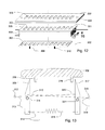
- FIG. 12 illustrates a non-limiting exploded view of the preferred embodiment of a Damper/Register Unit (RDU)
- RDU Damper/Register Unit
- FIG. 13 illustrates a non-limiting example of a side sectional view of certain electrical and mechanical components that comprise the actuator mechanism the DRU in FIG. 12
- FIG. 14 illustrates a non-limiting example of a side sectional view of certain electrical and mechanical components that comprise the actuator mechanism the DRU in FIG. 12 in the closed position.
- FIG. 15 illustrates a non-limiting example of a side sectional view of certain electrical and mechanical components that comprise the actuator mechanism the DRU in FIG. 12 in the open position.
- FIG. 16 illustrates a non-limiting example of a top sectional view of certain electrical, electronic and mechanical components that comprise the actuator mechanism the DRU in FIG. 12
- FIG. 17 illustrates a non-limiting example of a side sectional view of certain electrical and mechanical components that comprise the actuator mechanism the DRU in FIG. 12 showing the damper plate in the closed position and certain surface detail.
- FIG. 18 illustrates a non-limiting example of an alternative embodiment of a Wall Sensor Unit (WSU) that includes buttons for controlling lighting.
- WSU Wall Sensor Unit
- Wall Sensor Unit, 100 is representative of a device that includes a display sub system such as a LCD 102 , one or more button, 103 , an environmental sensor subsystem composed of temperature and humidity sensors, 105 , an acoustic sensor, 106 , a motion sensor, 107 , and a light sensor, 109 . Also in FIG. 1 is a representation of a register/damper unit, 101 , that acts as a terminal unit and includes vent holes, 110 , a duct skirt, 111 , and one or more optional mounting holes for screws, 112 .
- FIG. 2 shows block drawing of an embodiment of the system with four zones, 97 , with each zone having a Wall Sensor Unit, 100 , a register/damper unit, 101 , supply duct work 89 , and a furnace or other HVAC plant, 99 .
- a return duct to the HVAC plant 99 .
- a wired connection from a single wall sensor unit is shown to the HVAC plant, 93 or as an alternate embodiment a system controller 92 .
- a duct pressure or flow sensor is shown 94 .
- a fresh-air economizer is shown, 91 , in the return air duct with a wireless control unit 92 , controlling the flow direction.
- An outside air enthalpy sensor is shown, 90 .
- FIG. 3 shows the electronic components of a preferred embodiment of the wall sensor unit shown in FIG. 1 that includes a display system sub system such as a LCD 102 , one or more buttons, 103 , an environmental sensor subsystem composed of temperature and humidity sensors, 105 , an acoustic sensor, 106 , a motion sensor, 107 , a light sensor, 109 , a RF antenna, 113 , one or more batteries, 114 , one or more persistent data storage devices such as FLASH, battery backed SRAM, a hard disk drive or other persistent data storage device for holding the program and data, 115 , a relay, solid state relay, direct logic level output or other digital interface for signaling HVAC devices, 116 , analog signal conditioning and buffering circuits such as a transistor or MOSFT, 116 , for controlling the HVAC interface, 116 , the connection points such as a screw or push terminal to the HVAC equipment, 119 , and one or more CPUs that support a wireless communication protocol, such as a ZigBee,
- FIG. 4 shows the electronic components of a preferred embodiment of the damper register unit shown in FIG. 1 that includes an actuator such as a DC motor, a solenoid, a shape memory alloy device, 121 , a RF antenna, 113 , one or more batteries, 114 , one or more persistent data storage devices such as FLASH, battery backed SRAM, a hard disk drive or other persistent data storage device for holding the program and data, 115 , a pair of analog signal conditioning and buffering circuits such as a transistor or MOSFT, 120 , for controlling the actuator, 121 and one or more CPUs that support a wireless communication protocol, such as a ZigBee, and can support the basic control and I/O functions of an embedded processor.
- an actuator such as a DC motor, a solenoid, a shape memory alloy device, 121 , a RF antenna, 113 , one or more batteries, 114 , one or more persistent data storage devices such as FLASH, battery backed SRAM, a hard disk drive or other persistent
- FIG. 5 shows an embodiment of a data structure for storing occupancy events.
- Each bit stores a history for a 15 minute block of time with each byte representing 8 15 minute time blocks or 2 hours of time.
- a value of 1 in a bit represents occupancy during that block of time and a 0 represents non-occupancy.
- the bytes are arranged continuously in chronological order with 17,531 bytes used to represent 4 calender years, 214 .
- This calendar includes a leap year day. The calendar is arranged starting with January 1 in the first byte and with leap year as the last year.
- This calendar is stored in persistent memory for each zone such as is shown in 115 in FIG. 3 . Occupancy is recorded in 15 minute increments and 8 samples (2 hours) are combined into a byte.
- this function is called with a string command where the first 16 bit unsigned integer (uint 16 ), 210 , is the number of weight code value pairs following (excluding the size of the length value). Following the length value are pairs of 8 bit unsigned integers (uint 8 s ), 211 , that indicate the weight function shown as a hexadecimal number, 212 , and weight value shown as a hexadecimal number, 213 .
- the weight value, 213 is optimized by a genetic algorithm working in the background using the history of occupancy, 214 , and the error log, 215 , to evaluate the fitness of the existing population (weight values) and the new population.
- FIG. 8 is a flow chart of one embodiment of an algorithm for calculating a likelihood of an occupancy occurring during a given time slot.
- the input values are the initial date-time, DATE, and offset between previous dates-times, Offset, initial values are initiated to 0 with j used as a iteration counter and X used as a working value to build the result, 225 , the value X is shifted left one bit, 226 , the number of iterations is indicated by n, the boolean that represents the date-time indicated by Date is located in the data base, 228 , and added to the working value X, 227 , the date-time is decremented by the value indicated by the input, Offset, and wrapped around to the far end of the database if the date-time is less than the start of the database, 229 , the iteration counter j is incremented, 230 , if the iteration counter is greater than zero then we branch to 226 , but when the iteration counter reaches zero the function
- Typical values for n would be 4 and for Offset would be 15 minutes, hour, day, month or year. Additionally, the Offset can be date logical, for example, decrementing by weekday such that that decrementing from a Monday would result in the previous Friday or decrementing by weekend-day such that that decrementing from a Sunday would result in the previous Saturday.
- FIG. 9 represents a pattern of motion by an occupant.
- the system coordinator 95 or 100 , runs a background process to poll the occupancy records of each wall sensor unit for the previous 28 days looking for reproduced sequences of events that occur at approximately the same time.
- the system coordinator builds, maintains and stores a list of these events such that if an occupancy event occurs the subsequent zones are conditioned to the set point temperature.
- FIG. 10 represents the data flow in an installation.
- the damper/registers, 101 -A, 101 -B, 101 -C, 101 -D, furnace sensors/controls, 92 , 94 , 95 and outside sensors 90 act as limited function end device, the wall sensor units, 100 -A, 100 -B and 100 -C all act as at least a routers.
- either wall sensor 100 A or furnace control 95 would act as the network coordinator.
- a furnace control unit would not be needed.
- the arrows show how a network can form and how data can be routed through different nodes.
- a link to a PC or other networking device, 91 allows for a web interface for displaying to the homeowner the current status of the system and to allow for dynamic load shedding and setback/set point changes, support of real-time metering and smart grid functions.
- the wireless communication between all or come of the wireless links can be replaced with a wired link such as CANBUS.
- FIG. 11 represents the process that the coordinator goes through when a conditioning request arrives from a wall sensor or from the coordinator itself.
- a request for conditioning arrives at the coordinator each of the other wall sensor units are required to determine their likelihood of requiring conditioning. Enough damper/registers are opened according to the likelihood of each zone requiring conditioning until enough open cross section is provided to allow for efficient energy transfer from the central plant, to keep noise to a minimum and to prevent damage to the duct work.
- FIG. 12 represents an exploded view of the preferred embodiment of the damper/register.
- a top cover, 300 that has a plurality of vent holes for the passage of air, 303 , and a plurality of screw mount holes, 304 .
- a functional unit, 301 that has a plurality of vent holes for the passage of air, 303 , that attaches to the bottom of the top cover has a duct skirt, 306 and a top mount, 305 .
- the damper plate, 302 that has a plurality of vent holes for the passage of air, 303 , and push tabs, 308 and 316 .
- FIG. 13 represents the mechanism that opens and closes the register/damper in FIG. 12 .
- Two Shape Memory Alloy (SMA) wires, 310 and 320 are attached to the respective metal pushers and anchor points, 318 and 312 .
- the SMA wires have lead wires, 319 , 313 , respectively.
- There is a metallic spring, 315 that is connected to each of the pushers on the opposite side of the pivot from where the SMA wires are attached with a lead wire, 314 , attached to the spring.
- the relationship between the pushers and the damper plate, 302 , and push tabs 308 and 316 is shown with a partial display of the damper plate.
- the damper plate in this figure is shown in an intermediate open/close position.
- FIG. 14 represents the same components as shown in FIG. 13 , but shows SMA wire 310 actively contracting and damper plate 302 in the open position.
- FIG. 15 represents the same components as shown in FIG. 13 , but shows SMA wire 320 actively contracting and damper plate 302 in the closed position.
- FIG. 16 is a section view from above of the main register/damper piece, 301 at the level of the section shows the duct skirt, 306 , from FIG. 13 . Included in this figure are batteries, 322 , the pivots 311 and 321 , the anchor points, 312 and 318 , the SMA wires, 319 and 320 , the printed circuit board for the electronics, 323 and an internal mounting support 324 . Not seen at this section level is the spring, 315 and the lead wires, 314 , 313 and 319 .
- FIG. 17 represents a section view from the side of the register/damper from FIG. 12 .
- the damper plate is shown in the closed position. The surfaces of the damper plate and functional unit that meet are roughed sufficiently to prevent uncommanded motion of the damper plate as indicated in the enlarged view indicated by 324 .
- FIG. 18 shows an alternative embodiment of the wall sensor unit, 100 from FIG. 1 .
- this embodiment includes a display sub system such as a LCD 102 , one or more button, 103 , an environmental sensor subsystem composed of temperature and humidity sensors, 105 , an acoustic sensor, 106 , a motion sensor, 107 , and a light sensor, 109 .
- a display sub system such as a LCD 102 , one or more button, 103
- an environmental sensor subsystem composed of temperature and humidity sensors, 105 , an acoustic sensor, 106 , a motion sensor, 107 , and a light sensor, 109 .
- three momentary switches 351 , 352 , 353 that are used for raising, toggling and dimming respectively a remote ZigBee light.
- the form factor is able to fit into a standard dual position modern style mud plate, 354 and standard two position junction box.
- the systems, methods, and techniques described herein may be implemented in digital electronic circuitry, computer hardware, firmware, software, or in combinations of these elements.
- Apparatus embodying these techniques may include appropriate input and output devices, a computer processor, and a computer program product tangibly embodied in a machine-readable storage device for execution by a programmable processor.
- a process embodying these techniques may be performed by a programmable processor executing a program or script of instructions to perform desired functions by operating on input data and generating appropriate output.
- the techniques may be implemented in one or more computer programs or scripts that are executable on a programmable system including at least one programmable processor coupled to receive data and instructions from, and to transmit data and instructions to, a data storage system, at least one input device, and at least one output device.
- Suitable processors include, by way of example, both general and special purpose microprocessors.
- a processor will receive instructions and data from a read-only memory and/or a random access memory.
- Storage devices suitable for tangibly embodying computer program instructions and data include all forms of volatile and non-volatile memory, including by way of example semiconductor memory devices, such as Erasable Programmable Read-Only Memory (EPROM), Electrically Erasable Programmable Read-Only Memory (EEPROM), and flash memory devices; magnetic disks such as internal hard disks and removable disks; magneto-optical disks; and Compact Disc Read-Only Memory (CD-ROM). Any of the foregoing may be supplemented by, or incorporated in, specially-designed ASICs (application-specific integrated circuits).
- the computer program instructions or scripts may also be provided as data signals embodied in a carrier wave or other propagation medium via a communication link (e.g., a modem or wired or wireless network connection).
- the system includes Wall Sensor Units (WSU) that superficially appear to be programmable thermostats, but include temperature/humidity, occupancy sensors, advanced software, processor, FLASH memory for recording occupancy information and a ZigBee wireless network capability.
- WSU Wall Sensor Unit
- the system also includes ZigBee based wireless battery operated Damper/Register Units (DRUs) that are actuated by Shape Memory Alloy (SMA) wires.
- DRUs ZigBee based wireless battery operated Damper/Register Units
- SMA Shape Memory Alloy
- the preferred embodiment for the DRU includes two SMAs that when commanded each actuate a pusher that in turn each each presses on a push tab on the damper plate, and a single shared return spring.
- Each of the components have an embedded MCU and ZigBee support.
- the system is intended to support zoned control and as each building the system is installed into is likely to be different the number and configuration of each installation will be different.
- Residential HVAC zones typical are based on a room that has a door that closes. There are some places where rooms are connected without doors that close such as is often found between kitchens and living rooms in open plan homes. In these cases where the air between rooms communicates well they may be treated as one zone.
- the DRU Most communication between the WSU and DRU is from the WSU to the DRU ordering the DRU to open or close.
- the DRU will communicate back to the WSU open/close state confirmation, temperature, low battery and fault data.
- the DRUs act as a ZigBee End Device (ZED).
- Most WSU's function as ZigBee Router (ZR), but one WSU will act as a ZigBee coordinator (ZC) unless a HVAC central controller is present in which case the HVAC central controller acts as the ZC.
- the WSU redundant occupancy sensors are able determine if the room is occupied. Redundant sensors are used because often one time of sensor will not be able to determine if a human is present. For example, PIR sensors can only detect humans when they move and microphones can only detect their presence when they make noise. Conversely, occupancy sensor often have false positives. By combining the inputs from multiple sensor and filtering, a much more accurate picture of occupancy can be obtained.
- Each WSU records the occupancy of its zone in its FLASH memory in 15 minute increments with a rolling record for 4 years. The occupancy record is used to predict future occupancy. The occupancy record is examined using a Decaying Occupancy Temporal (DOT) Algorithm by looking at periodic occupancy records with decaying impact from older records.
- DOT Decaying Occupancy Temporal
- Occupancy is recorded as 1 if occupied and 0 in unoccupied. For example if looking at the past four days then eight times the occupancy value the same time one day before the target record is added with four time sthe occupancy value from two days before plus two times the value of occupancy record from three days before plus the occupancy value from four days before.
- This algorithm can be used over different time intervals such as past n 15 minutes, past n hours, past n days, past n months, past n years or time-logical intervals such as past n week days, past n weekend days, same day of month past n months. These various occupancy interval measurements are weighted and summed and compared against a user configurable economy/comfort threshold.
- the weighing values for the various occupancy interval measurements are determined by a genetic algorithm running in the background that uses the uses the weighing values as the genetic representation and performance with recent occupancy history as a fitness function to select the weighting values.
- Each WSU also keeps a record of set points, reset points and ventilation rates in FLASH in 15 minute increments based on a one week calendar that can be altered by the occupants.
- a request is sent to the ZC. Every 15 minutes the ZC sends a command to the WSUs to execute the occupancy prediction algorithm and returns any conditioning results to the ZC. If there is a conditioning request pending the ZC opens a sufficient number of DRUs to keep the pressure of the ducts low enough to maintain a high enough air flow for heat transfer, HVAC central plant safety and to prevent damage to the duct system.
- the DRUs to open is determined by current HVAC needs and by near future HVAC needs by the ZC querying the WSUs that will run their respective prediction algorithms for current and near future occupancy as well as distance from current set/setback point.
- the ZC opens the next most likely DRUs to open until enough are opened to provide adequate air flow in the duct network and to also provide minimum building ventilation.
- the WSU contain a full set of algorithms for setback, pre-cooling, fresh air economizers, load shedding, economic/comfort trade-offs and time of day meters optimization.
- the ZC also contains a full set of algorithms for controlling all standard HVAC plant types as well as relays for signaling the central HVAC plant.
Abstract
Description
Claims (10)
Priority Applications (3)
| Application Number | Priority Date | Filing Date | Title |
|---|---|---|---|
| US12/284,795 US8086352B1 (en) | 2007-10-04 | 2008-09-25 | Predictive efficient residential energy controls |
| US13/304,170 US20120072030A1 (en) | 2007-10-04 | 2011-11-23 | System and method of predictive occupancy room conditioning |
| US13/304,165 US20120072031A1 (en) | 2007-10-04 | 2011-11-23 | Shape memory alloy damper/register unit |
Applications Claiming Priority (2)
| Application Number | Priority Date | Filing Date | Title |
|---|---|---|---|
| US99742607P | 2007-10-04 | 2007-10-04 | |
| US12/284,795 US8086352B1 (en) | 2007-10-04 | 2008-09-25 | Predictive efficient residential energy controls |
Related Child Applications (2)
| Application Number | Title | Priority Date | Filing Date |
|---|---|---|---|
| US13/304,165 Continuation US20120072031A1 (en) | 2007-10-04 | 2011-11-23 | Shape memory alloy damper/register unit |
| US13/304,170 Continuation US20120072030A1 (en) | 2007-10-04 | 2011-11-23 | System and method of predictive occupancy room conditioning |
Publications (1)
| Publication Number | Publication Date |
|---|---|
| US8086352B1 true US8086352B1 (en) | 2011-12-27 |
Family
ID=45349897
Family Applications (3)
| Application Number | Title | Priority Date | Filing Date |
|---|---|---|---|
| US12/284,795 Expired - Fee Related US8086352B1 (en) | 2007-10-04 | 2008-09-25 | Predictive efficient residential energy controls |
| US13/304,165 Abandoned US20120072031A1 (en) | 2007-10-04 | 2011-11-23 | Shape memory alloy damper/register unit |
| US13/304,170 Abandoned US20120072030A1 (en) | 2007-10-04 | 2011-11-23 | System and method of predictive occupancy room conditioning |
Family Applications After (2)
| Application Number | Title | Priority Date | Filing Date |
|---|---|---|---|
| US13/304,165 Abandoned US20120072031A1 (en) | 2007-10-04 | 2011-11-23 | Shape memory alloy damper/register unit |
| US13/304,170 Abandoned US20120072030A1 (en) | 2007-10-04 | 2011-11-23 | System and method of predictive occupancy room conditioning |
Country Status (1)
| Country | Link |
|---|---|
| US (3) | US8086352B1 (en) |
Cited By (42)
| Publication number | Priority date | Publication date | Assignee | Title |
|---|---|---|---|---|
| US20110166710A1 (en) * | 2009-11-09 | 2011-07-07 | The Wiremold Company | Methods and systems to simulate and optimize whole building comfort and energy performance |
| US20130013121A1 (en) * | 2011-02-24 | 2013-01-10 | Henze Gregor P | Integration of commercial building operations with electric system operations and markets |
| US20130252550A1 (en) * | 2012-03-21 | 2013-09-26 | Mark Alan Johnson | Wireless Device Pairing Recovery |
| WO2013170791A1 (en) * | 2012-05-17 | 2013-11-21 | CHAN, Hun Man Lena | Information control system |
| US20140266671A1 (en) * | 2013-03-12 | 2014-09-18 | Honeywell International Inc. | Mechanism and approach for monitoring building automation systems through user defined content notifications |
| EP2857921A1 (en) * | 2013-10-01 | 2015-04-08 | Genius Concepts Ltd | Intelligent temperature control system |
| US20150223310A1 (en) * | 2008-09-03 | 2015-08-06 | Lutron Electronics Co., Inc. | Radio-frequency lighting control system with occupancy sensing |
| WO2015162359A1 (en) * | 2014-04-25 | 2015-10-29 | Somfy Sas | Method for controlling and/or monitoring at least one actuator |
| US20160003492A1 (en) * | 2014-07-07 | 2016-01-07 | Trane International Inc. | Thermistor Emulating CT Clamp |
| US20160195866A1 (en) * | 2013-03-13 | 2016-07-07 | Johnson Controls Technology Company | Systems and methods for energy cost optimization in a building system |
| US20160258639A1 (en) * | 2015-03-06 | 2016-09-08 | Ruskin Company | Energy harvesting damper control and method of operation |
| US20160357199A1 (en) * | 2015-06-07 | 2016-12-08 | Kenny Lofland Matlock | Hvac register and multiple hvac register system |
| US9524529B2 (en) | 2012-11-07 | 2016-12-20 | Cenergistic Llc | Interval analysis tool for energy consumption |
| US9903606B2 (en) | 2014-04-29 | 2018-02-27 | Vivint, Inc. | Controlling parameters in a building |
| US20180120783A1 (en) * | 2016-11-02 | 2018-05-03 | Edison Labs, Inc. | Adaptive control systems methods for buildings with security |
| US20180120781A1 (en) * | 2016-11-02 | 2018-05-03 | Edison Labs, Inc. | Adaptive control methods for buildings with security |
| US20180120784A1 (en) * | 2016-11-02 | 2018-05-03 | Edison Labs, Inc. | Switch terminal methods with wiring components secured to circuitry wiring without external live points of contact |
| US20180120779A1 (en) * | 2016-11-02 | 2018-05-03 | Edison Labs, Inc. | Adaptive control systems for buildings with redundant circuitry |
| US10088814B2 (en) | 2013-03-13 | 2018-10-02 | Johnson Controls Technology Company | System identification and model development |
| WO2018191251A1 (en) * | 2017-04-10 | 2018-10-18 | The Research Foundation For The State University Of New York | System and method for occupancy-driven register airflow control |
| US10126009B2 (en) | 2014-06-20 | 2018-11-13 | Honeywell International Inc. | HVAC zoning devices, systems, and methods |
| US10132553B2 (en) | 2016-07-05 | 2018-11-20 | Johnson Controls Technology Company | Drain pan removable without the use of tools |
| US10146191B2 (en) | 2016-11-02 | 2018-12-04 | Edison Labs, Inc. | Switch terminal system with spatial relationship information |
| US10190794B1 (en) | 2014-10-13 | 2019-01-29 | Arzel Zoning Technology, Inc. | System and apparatus for wireless environmental zone control |
| US20190033797A1 (en) * | 2016-11-02 | 2019-01-31 | Edison Labs, Inc. | Adaptive control systems for buildings with redundant circuitry |
| US10197979B2 (en) | 2014-05-30 | 2019-02-05 | Vivint, Inc. | Determining occupancy with user provided information |
| US10241477B2 (en) * | 2016-11-02 | 2019-03-26 | Edison Labs, Inc. | Adaptive control methods for buildings with redundant circuitry |
| US10254722B2 (en) | 2016-11-02 | 2019-04-09 | Edison Labs, Inc. | Switch terminal system with display |
| US10268168B2 (en) | 2016-11-02 | 2019-04-23 | Edison Labs, Inc. | Adaptive control systems and methods for buildings |
| US10317099B2 (en) | 2015-04-16 | 2019-06-11 | Air Distribution Technologies Ip, Llc | Variable air volume diffuser and method of operation |
| US10401805B1 (en) * | 2016-11-02 | 2019-09-03 | Edison Labs, Inc. | Switch terminal system with third party access |
| US10474112B2 (en) | 2016-11-02 | 2019-11-12 | Edison Labs, Inc. | Adaptive control systems for buildings with dual band slot antenna |
| CN110470428A (en) * | 2019-09-09 | 2019-11-19 | 西安电子科技大学 | A kind of on-line dynamic balancing adjustment device of marmem driving |
| US10481563B2 (en) | 2016-11-02 | 2019-11-19 | Edison Labs, Inc. | Adaptive control methods for buildings with dual band slot antenna |
| US10580097B2 (en) * | 2013-03-13 | 2020-03-03 | Johnson Controls Technology Company | Systems and methods for cascaded model predictive control |
| US10642231B1 (en) * | 2016-11-02 | 2020-05-05 | Edison Labs, Inc. | Switch terminal system with an activity assistant |
| US10704800B2 (en) | 2016-09-28 | 2020-07-07 | Air Distribution Technologies Ip, Llc | Tethered control for direct drive motor integrated into damper blade |
| US10839302B2 (en) | 2015-11-24 | 2020-11-17 | The Research Foundation For The State University Of New York | Approximate value iteration with complex returns by bounding |
| US10948215B2 (en) | 2014-10-13 | 2021-03-16 | Arzel Zoning Technology, Inc. | System and method for wireless environmental zone control |
| US10982875B2 (en) * | 2017-08-13 | 2021-04-20 | Standard Euler, Inc. | RF antenna positioning techniques |
| US11099533B2 (en) | 2014-05-07 | 2021-08-24 | Vivint, Inc. | Controlling a building system based on real time events |
| US11458808B2 (en) * | 2020-04-22 | 2022-10-04 | GM Global Technology Operations LLC | Features of shutter system using modular SMA spring actuator |
Families Citing this family (39)
| Publication number | Priority date | Publication date | Assignee | Title |
|---|---|---|---|---|
| US20110295430A1 (en) * | 2010-05-26 | 2011-12-01 | Andrey Kouninski | Apparatus And Method For Managing Heating Or Cooling Of An Area In A Building |
| US10215436B1 (en) | 2011-05-02 | 2019-02-26 | John M. Rawski | Full spectrum universal controller |
| EP2878894B1 (en) * | 2012-05-14 | 2018-01-31 | Mitsubishi Electric Corporation | Air conditioning system |
| EP2856275A4 (en) | 2012-05-25 | 2015-12-16 | Hewlett Packard Development Co | Providing a model of impact of a cooling infrastructure |
| KR102043194B1 (en) * | 2012-07-25 | 2019-11-11 | 엘지전자 주식회사 | Air-conditioner management system and method for controlling air-conditioner |
| GB2508238A (en) * | 2012-11-27 | 2014-05-28 | Aidan Paul Ruff | Apparatus arranged to control a space heating/cooling system |
| US10088186B2 (en) * | 2013-02-07 | 2018-10-02 | Honeywell International Inc. | Building management system with power efficient discrete controllers |
| US10094584B2 (en) * | 2013-02-07 | 2018-10-09 | Honeywell International Inc. | Building management system with programmable IR codes |
| US10359791B2 (en) * | 2013-02-07 | 2019-07-23 | Honeywell International Inc. | Controller for controlling a building component of a building management system |
| US10330335B2 (en) * | 2013-02-07 | 2019-06-25 | Honeywell International Inc. | Method and system for detecting an operational mode of a building control component |
| WO2014123531A1 (en) * | 2013-02-07 | 2014-08-14 | Honeywell International Inc. | Building control system with distributed control |
| US10169833B2 (en) | 2013-05-14 | 2019-01-01 | University Of Florida Research Foundation, Incorporated | Using customer premises to provide ancillary services for a power grid |
| US10230240B2 (en) | 2013-10-22 | 2019-03-12 | University Of Florida Research Foundation, Incorporated | Low-frequency ancillary power grid services |
| WO2015089295A2 (en) * | 2013-12-12 | 2015-06-18 | University Of Florida Research Foundation, Inc. | Comfortable, energy-efficient control of a heating, ventilation, and air conditioning system |
| KR102233616B1 (en) * | 2014-02-25 | 2021-03-30 | 삼성전자 주식회사 | Air conditioner and operation method thereof |
| US10664772B1 (en) | 2014-03-07 | 2020-05-26 | Steelcase Inc. | Method and system for facilitating collaboration sessions |
| US9716861B1 (en) | 2014-03-07 | 2017-07-25 | Steelcase Inc. | Method and system for facilitating collaboration sessions |
| CA2946891A1 (en) * | 2014-05-07 | 2015-11-12 | Vivint, Inc. | Controlling a building system based on real time events |
| WO2015174795A1 (en) * | 2014-05-15 | 2015-11-19 | Samsung Electronics Co., Ltd. | Method and apparatus for controlling temperature |
| US9380682B2 (en) | 2014-06-05 | 2016-06-28 | Steelcase Inc. | Environment optimization for space based on presence and activities |
| US9766079B1 (en) | 2014-10-03 | 2017-09-19 | Steelcase Inc. | Method and system for locating resources and communicating within an enterprise |
| US9955318B1 (en) | 2014-06-05 | 2018-04-24 | Steelcase Inc. | Space guidance and management system and method |
| US11744376B2 (en) | 2014-06-06 | 2023-09-05 | Steelcase Inc. | Microclimate control systems and methods |
| US10433646B1 (en) | 2014-06-06 | 2019-10-08 | Steelcaase Inc. | Microclimate control systems and methods |
| JP6561562B2 (en) * | 2014-06-30 | 2019-08-21 | パナソニック インテレクチュアル プロパティ コーポレーション オブ アメリカPanasonic Intellectual Property Corporation of America | Cooking apparatus, information display apparatus, control method, cooking utensil, and computer program |
| US9852388B1 (en) | 2014-10-03 | 2017-12-26 | Steelcase, Inc. | Method and system for locating resources and communicating within an enterprise |
| US10429809B2 (en) | 2015-05-01 | 2019-10-01 | Lutron Technology Company Llc | Display and control of load control devices in a floorplan |
| US10733371B1 (en) | 2015-06-02 | 2020-08-04 | Steelcase Inc. | Template based content preparation system for use with a plurality of space types |
| KR20170068958A (en) * | 2015-12-10 | 2017-06-20 | 삼성전자주식회사 | Apparatus and method for controlling temperature in air conditioning system |
| US9921726B1 (en) | 2016-06-03 | 2018-03-20 | Steelcase Inc. | Smart workstation method and system |
| CN106020152A (en) * | 2016-07-05 | 2016-10-12 | 江苏长宁电力科技有限公司 | Building environment energy conservation management system |
| US10393401B2 (en) | 2016-08-22 | 2019-08-27 | Air Distribution Technologies Ip, Llc | Direct drive motor integrated into damper blade |
| CN106325328B (en) * | 2016-09-30 | 2018-04-13 | 深圳春沐源控股有限公司 | A kind of method and device of planting equipment temperature adjustment |
| US10788232B2 (en) * | 2016-10-21 | 2020-09-29 | Innovative Building Energy Control | Air circulation systems and methods |
| US11402111B2 (en) | 2016-11-03 | 2022-08-02 | Air Distribution Technologies Ip, Llc | Staged damper system |
| US10264213B1 (en) | 2016-12-15 | 2019-04-16 | Steelcase Inc. | Content amplification system and method |
| US10859282B2 (en) * | 2018-03-19 | 2020-12-08 | Ajamian Integrated Research Corp. | HVAC balancing and optimization systems |
| KR20200084380A (en) * | 2018-12-20 | 2020-07-13 | 전자부품연구원 | Smart Home Airconditioner Automatic control system based on Artificial Intelligence |
| US11379765B2 (en) | 2020-11-25 | 2022-07-05 | Bank Of America Corporation | Occupancy prediction using real-time information |
Citations (26)
| Publication number | Priority date | Publication date | Assignee | Title |
|---|---|---|---|---|
| US3567115A (en) | 1969-05-19 | 1971-03-02 | Honeywell Inc | Zone temperature control system |
| US4475685A (en) | 1983-03-07 | 1984-10-09 | At&T Bell Laboratories | Control system for efficient intermittent operation of building HVAC equipment |
| US4479604A (en) | 1982-12-30 | 1984-10-30 | Didner Robert S | Zoned control system |
| US4485864A (en) | 1981-01-14 | 1984-12-04 | Flair-Emsco Corporation | Occupancy responsive temperature control system |
| US4530395A (en) | 1982-10-14 | 1985-07-23 | Parker Electronics, Inc. | Single zone HVAC controlled for operation in multiple zone arrangement |
| US4582249A (en) | 1984-12-17 | 1986-04-15 | Honeywell Inc. | Zone control system for energy conservation |
| US5476221A (en) | 1994-01-28 | 1995-12-19 | Seymour; Richard L. | Easy-to-install thermostatic control system based on room occupancy |
| US5544809A (en) | 1993-12-28 | 1996-08-13 | Senercomm, Inc. | Hvac control system and method |
| US5682949A (en) | 1992-05-22 | 1997-11-04 | Globalmic, Inc. | Energy management system |
| US5785243A (en) | 1997-04-11 | 1998-07-28 | Cross; Andrew | Climate control sensor apparatus |
| US5944098A (en) | 1997-07-17 | 1999-08-31 | Jackson; Ronald E. | Zone control for HVAC system |
| US6196468B1 (en) | 1998-07-24 | 2001-03-06 | Dennis Guy Young | Air conditioning and heating environmental control sensing system |
| US6349883B1 (en) | 1999-02-09 | 2002-02-26 | Energy Rest, Inc. | Energy-saving occupancy-controlled heating ventilating and air-conditioning systems for timing and cycling energy within different rooms of buildings having central power units |
| US20020134849A1 (en) | 2001-03-02 | 2002-09-26 | Disser James R. | Method and apparatus for reducing energy consumption in heating, ventilating, and air conditioning of unoccupied building zones |
| US6645066B2 (en) | 2001-11-19 | 2003-11-11 | Koninklijke Philips Electronics N.V. | Space-conditioning control employing image-based detection of occupancy and use |
| US6726113B2 (en) | 2002-02-25 | 2004-04-27 | Carrier Corporation | Temperature control strategy utilizing neural network processing of occupancy and activity level sensing |
| US6865596B1 (en) * | 1999-06-09 | 2005-03-08 | Amx Corporation | Method and system for operating virtual devices by master controllers in a control system |
| US6909921B1 (en) | 2000-10-19 | 2005-06-21 | Destiny Networks, Inc. | Occupancy sensor and method for home automation system |
| US20050143863A1 (en) * | 2003-12-19 | 2005-06-30 | Margaret Ruane | Building control system field panel having integrated web server |
| US6983889B2 (en) | 2003-03-21 | 2006-01-10 | Home Comfort Zones, Inc. | Forced-air zone climate control system for existing residential houses |
| US20060172694A1 (en) * | 2005-02-03 | 2006-08-03 | Air System Components, L.P. | Thermal auto-change air diffuser |
| US7138732B2 (en) | 2000-08-04 | 2006-11-21 | Energy Technologies, L.L.C. | Security and energy control system and method |
| US20070220907A1 (en) * | 2006-03-21 | 2007-09-27 | Ehlers Gregory A | Refrigeration monitor unit |
| US20070233323A1 (en) | 2006-04-04 | 2007-10-04 | Panduit Corp. | Building automation system controller |
| US20080121729A1 (en) | 2006-09-12 | 2008-05-29 | Home Comfort Zones, Inc. | Control interface for environment control systems |
| US7392661B2 (en) | 2003-03-21 | 2008-07-01 | Home Comfort Zones, Inc. | Energy usage estimation for climate control system |
Family Cites Families (14)
| Publication number | Priority date | Publication date | Assignee | Title |
|---|---|---|---|---|
| JPH0139909Y2 (en) * | 1984-11-07 | 1989-11-30 | ||
| US5005678A (en) * | 1989-03-03 | 1991-04-09 | The Boeing Company | Method and apparatus for sensing and damping vibration |
| US5211371A (en) * | 1991-07-22 | 1993-05-18 | Advanced Control Technologies, Inc. | Linearly actuated valve |
| US7216021B2 (en) * | 2003-10-30 | 2007-05-08 | Hitachi, Ltd. | Method, system and computer program for managing energy consumption |
| US7502768B2 (en) * | 2004-02-27 | 2009-03-10 | Siemens Building Technologies, Inc. | System and method for predicting building thermal loads |
| US20050207079A1 (en) * | 2004-03-17 | 2005-09-22 | Tiller David S | System and apparatus for a multifunctional powerline carrier device with data management and power surge protector |
| US7275377B2 (en) * | 2004-08-11 | 2007-10-02 | Lawrence Kates | Method and apparatus for monitoring refrigerant-cycle systems |
| US7156316B2 (en) * | 2004-10-06 | 2007-01-02 | Lawrence Kates | Zone thermostat for zone heating and cooling |
| US7163156B2 (en) * | 2004-10-06 | 2007-01-16 | Lawrence Kates | System and method for zone heating and cooling |
| GB2439490B (en) * | 2005-03-08 | 2008-12-17 | Radio Usa Inc E | Systems and methods for modifying power usage |
| JP2007155149A (en) * | 2005-11-30 | 2007-06-21 | Toyoda Gosei Co Ltd | Blade driving device of swing resistor |
| US20080177678A1 (en) * | 2007-01-24 | 2008-07-24 | Paul Di Martini | Method of communicating between a utility and its customer locations |
| US8020777B2 (en) * | 2007-01-29 | 2011-09-20 | Lawrence Kates | System and method for budgeted zone heating and cooling |
| US20090065595A1 (en) * | 2007-09-12 | 2009-03-12 | Lawrence Kates | System and method for zone heating and cooling using controllable supply and return vents |
-
2008
- 2008-09-25 US US12/284,795 patent/US8086352B1/en not_active Expired - Fee Related
-
2011
- 2011-11-23 US US13/304,165 patent/US20120072031A1/en not_active Abandoned
- 2011-11-23 US US13/304,170 patent/US20120072030A1/en not_active Abandoned
Patent Citations (29)
| Publication number | Priority date | Publication date | Assignee | Title |
|---|---|---|---|---|
| US3567115A (en) | 1969-05-19 | 1971-03-02 | Honeywell Inc | Zone temperature control system |
| US4485864A (en) | 1981-01-14 | 1984-12-04 | Flair-Emsco Corporation | Occupancy responsive temperature control system |
| US4530395A (en) | 1982-10-14 | 1985-07-23 | Parker Electronics, Inc. | Single zone HVAC controlled for operation in multiple zone arrangement |
| US4479604A (en) | 1982-12-30 | 1984-10-30 | Didner Robert S | Zoned control system |
| US4475685A (en) | 1983-03-07 | 1984-10-09 | At&T Bell Laboratories | Control system for efficient intermittent operation of building HVAC equipment |
| US4582249A (en) | 1984-12-17 | 1986-04-15 | Honeywell Inc. | Zone control system for energy conservation |
| US5682949A (en) | 1992-05-22 | 1997-11-04 | Globalmic, Inc. | Energy management system |
| US5544809A (en) | 1993-12-28 | 1996-08-13 | Senercomm, Inc. | Hvac control system and method |
| US5476221A (en) | 1994-01-28 | 1995-12-19 | Seymour; Richard L. | Easy-to-install thermostatic control system based on room occupancy |
| US5785243A (en) | 1997-04-11 | 1998-07-28 | Cross; Andrew | Climate control sensor apparatus |
| US5944098A (en) | 1997-07-17 | 1999-08-31 | Jackson; Ronald E. | Zone control for HVAC system |
| US6196468B1 (en) | 1998-07-24 | 2001-03-06 | Dennis Guy Young | Air conditioning and heating environmental control sensing system |
| US6349883B1 (en) | 1999-02-09 | 2002-02-26 | Energy Rest, Inc. | Energy-saving occupancy-controlled heating ventilating and air-conditioning systems for timing and cycling energy within different rooms of buildings having central power units |
| US6865596B1 (en) * | 1999-06-09 | 2005-03-08 | Amx Corporation | Method and system for operating virtual devices by master controllers in a control system |
| US7138732B2 (en) | 2000-08-04 | 2006-11-21 | Energy Technologies, L.L.C. | Security and energy control system and method |
| US6909921B1 (en) | 2000-10-19 | 2005-06-21 | Destiny Networks, Inc. | Occupancy sensor and method for home automation system |
| US20020134849A1 (en) | 2001-03-02 | 2002-09-26 | Disser James R. | Method and apparatus for reducing energy consumption in heating, ventilating, and air conditioning of unoccupied building zones |
| US6645066B2 (en) | 2001-11-19 | 2003-11-11 | Koninklijke Philips Electronics N.V. | Space-conditioning control employing image-based detection of occupancy and use |
| US6726113B2 (en) | 2002-02-25 | 2004-04-27 | Carrier Corporation | Temperature control strategy utilizing neural network processing of occupancy and activity level sensing |
| US6983889B2 (en) | 2003-03-21 | 2006-01-10 | Home Comfort Zones, Inc. | Forced-air zone climate control system for existing residential houses |
| US6997390B2 (en) | 2003-03-21 | 2006-02-14 | Home Comfort Zones, Inc. | Retrofit HVAC zone climate control system |
| US7188779B2 (en) | 2003-03-21 | 2007-03-13 | Home Comfort Zones | Zone climate control |
| US7207496B2 (en) | 2003-03-21 | 2007-04-24 | Home Comfort Zones, Inc. | Vent-blocking inflatable bladder for a retrofit HVAC zone control system |
| US7392661B2 (en) | 2003-03-21 | 2008-07-01 | Home Comfort Zones, Inc. | Energy usage estimation for climate control system |
| US20050143863A1 (en) * | 2003-12-19 | 2005-06-30 | Margaret Ruane | Building control system field panel having integrated web server |
| US20060172694A1 (en) * | 2005-02-03 | 2006-08-03 | Air System Components, L.P. | Thermal auto-change air diffuser |
| US20070220907A1 (en) * | 2006-03-21 | 2007-09-27 | Ehlers Gregory A | Refrigeration monitor unit |
| US20070233323A1 (en) | 2006-04-04 | 2007-10-04 | Panduit Corp. | Building automation system controller |
| US20080121729A1 (en) | 2006-09-12 | 2008-05-29 | Home Comfort Zones, Inc. | Control interface for environment control systems |
Non-Patent Citations (20)
| Title |
|---|
| Aakash Patel, Sharath Kumar, and Young Chul Song, "MiSo* SWECSTM Actuators, " Department of Mechanical Engineering University of Michigan, 2004, Ann Arbor, MI. |
| Canmet Energy Technology Centre [CETC], "Zoned Heating & Cooling Innovation", Natural Resources Canada, 2006, Ottawa, Ontario, Canada , 2007. |
| David Cross and David Judd, "Automatic Setback Thermostats: Measure Persistence and Customer Behavior" Proceedings of the 1997 International Energy Program Evaluation Conference, Chicago, Aug. 27-29, 1997. |
| David Shiller, Energy Star Marketing Manager, Energy Star Programmable Thermostat Proposal to Industry, US EPA, Washington DC, Jan. 11, 2006. |
| Ecologix Heating Technologies, Inc, "Zone Comfort System", Cambridge, Ontario, Canada, Jul. 7, 2006. |
| Energystar, "ENERGY STAR® Program Requirements for Programmable Thermostats Eligibility Criteria (Version 1.2)", US EPA, Washington DC, Jan. 30, 2008. |
| Harvey M. Sachs, Programmable Thermostats, ACEEE, Washington, D.C, Dec. 2004. |
| Home Comfort Zones, Inc., "MyTemp(TM) System", Beaverton, Oregon, Mar. 2008 (www.homecomfortzones.com). |
| Home Comfort Zones, Inc., "MyTemp™ System", Beaverton, Oregon, Mar. 2008 (www.homecomfortzones.com). |
| Home Comfort Zones, Inc., "Save Energy with the MyTemp(TM) System", Beaverton, Oregon, Apr. 1, 2008 (www.homecomfortzones.com). |
| Home Comfort Zones, Inc., "Save Energy with the MyTemp™ System", Beaverton, Oregon, Apr. 1, 2008 (www.homecomfortzones.com). |
| IEEE, The Institute of Electrical and Electronics Engineers, Inc., IEEE Std 802.15.4-2003 IEEE Standard for Information technology-Telecommunications and information exchange between systems-Local and metropolitan area networks-Specific requirements Part 15.4: Wireless Medium Access Control (MAC) and Physical Layer (PHY) Specifications for Low-Rate Wireless Personal Area Networks (LR-WPANs) Oct. 1, 2003. |
| M. C. Mozer, Dodier, R. H., Anderson, M., Vidmar, L., Cruickshank III, R. F., & Miller, D. (1995). "The neural network house: An overview." In L. Niklasson & M. Boden (Eds.), Current trends in connectionism (pp. 371-380). Hillsdale, NJ: Erlbaum. (http://www.cs.colorado.edu/~mozer/papers/nnh-overview.html). |
| M. C. Mozer, Dodier, R. H., Anderson, M., Vidmar, L., Cruickshank III, R. F., & Miller, D. (1995). "The neural network house: An overview." In L. Niklasson & M. Boden (Eds.), Current trends in connectionism (pp. 371-380). Hillsdale, NJ: Erlbaum. (http://www.cs.colorado.edu/˜mozer/papers/nnh—overview.html). |
| M. C. Mozer, L. Vidmar, and R. H Dodier, The Neurothermostat: Predictive optimal control of residential heating systems. In M. C. Mozer, M. I. Jordan, & T. Petsche (Eds.), Advances in Neural Information Processing Systems 9 (pp. 953-959). Cambridge, MA: MIT Press. (1997). (http://www.cs.colorado.edu/~mozer/papers/index.html). |
| M. C. Mozer, L. Vidmar, and R. H Dodier, The Neurothermostat: Predictive optimal control of residential heating systems. In M. C. Mozer, M. I. Jordan, & T. Petsche (Eds.), Advances in Neural Information Processing Systems 9 (pp. 953-959). Cambridge, MA: MIT Press. (1997). (http://www.cs.colorado.edu/˜mozer/papers/index.html). |
| M.R. Brambley, et al; Advanced Sensors and Controls for Building Applications: Market Assessment and Potential R & D Pathways. US DOE, Apr. 2005. Washington DC. |
| Nassif et al., "Evolutionary Algorithms for Multi-Objective Optimization in HVAC System Control Strategy", International Conference of the North American Fuzzy Information Processing Society No. 23, Banff AB , Canada (2004) , IEEE, Piscataway NJ, 2004. |
| Roger G. Gilbertson and Celene De Miranda, Muscle Wires Project Book, Mondo-Tronics, Incorporated; 3rd Rev edition (Nov. 2000). |
| Zigbee Alliance, ZigBee Specification V 1.0, Kinney Consulting LLC, 2004. |
Cited By (89)
| Publication number | Priority date | Publication date | Assignee | Title |
|---|---|---|---|---|
| US20150223310A1 (en) * | 2008-09-03 | 2015-08-06 | Lutron Electronics Co., Inc. | Radio-frequency lighting control system with occupancy sensing |
| US20190045606A1 (en) * | 2008-09-03 | 2019-02-07 | Lutron Electronics Co., Inc. | Control system with occupancy sensing |
| US10098206B2 (en) * | 2008-09-03 | 2018-10-09 | Lutron Electronics Co., Inc. | Radio-frequency lighting control system with occupancy sensing |
| US10462882B2 (en) * | 2008-09-03 | 2019-10-29 | Lutron Technology Company Llc | Control system with occupancy sensing |
| US11129262B2 (en) * | 2008-09-03 | 2021-09-21 | Lutron Technology Company Llc | Control system with occupancy sensing |
| US11743999B2 (en) | 2008-09-03 | 2023-08-29 | Lutron Technology Company Llc | Control system with occupancy sensing |
| US20110166710A1 (en) * | 2009-11-09 | 2011-07-07 | The Wiremold Company | Methods and systems to simulate and optimize whole building comfort and energy performance |
| US20130013121A1 (en) * | 2011-02-24 | 2013-01-10 | Henze Gregor P | Integration of commercial building operations with electric system operations and markets |
| US10373082B2 (en) * | 2011-02-24 | 2019-08-06 | Qcoefficient, Inc. | Integration of commercial building operations with electric system operations and markets |
| US9082296B2 (en) * | 2012-03-21 | 2015-07-14 | Invensys Systems, Inc. | Wireless device pairing recovery |
| US9251697B2 (en) * | 2012-03-21 | 2016-02-02 | Invensys Systems, Inc. | Means for pairing a hermetically sealed wireless device |
| US20130252550A1 (en) * | 2012-03-21 | 2013-09-26 | Mark Alan Johnson | Wireless Device Pairing Recovery |
| US20130252551A1 (en) * | 2012-03-21 | 2013-09-26 | Mark Alan Johnson | Means for Pairing A Hermetically Sealed Wireless Device |
| US9224287B2 (en) * | 2012-03-21 | 2015-12-29 | Invensys Systems, Inc. | Door ajar detection and recovery for a wireless door sensor |
| US20130252552A1 (en) * | 2012-03-21 | 2013-09-26 | Kimble Allyn Vitkus | Door Ajar Detection and Recovery for a Wireless Door Sensor |
| US9323255B2 (en) | 2012-05-17 | 2016-04-26 | Mark Kit Jiun Chan | Information control system |
| US10095250B2 (en) | 2012-05-17 | 2018-10-09 | Mark Kit Jiun Chan | Information control system |
| GB2517853A (en) * | 2012-05-17 | 2015-03-04 | Lena Hun Man Chan | Information control system |
| WO2013170791A1 (en) * | 2012-05-17 | 2013-11-21 | CHAN, Hun Man Lena | Information control system |
| GB2517853B (en) * | 2012-05-17 | 2017-02-15 | Lena Hun Man Chan | Information control system |
| US9524529B2 (en) | 2012-11-07 | 2016-12-20 | Cenergistic Llc | Interval analysis tool for energy consumption |
| US10162344B2 (en) * | 2013-03-12 | 2018-12-25 | Honeywell International Inc. | Mechanism and approach for monitoring building automation systems through user defined content notifications |
| US20140266671A1 (en) * | 2013-03-12 | 2014-09-18 | Honeywell International Inc. | Mechanism and approach for monitoring building automation systems through user defined content notifications |
| US11086276B2 (en) | 2013-03-13 | 2021-08-10 | Johnson Controls Tyco IP Holdings LLP | System identification and model development |
| US10007259B2 (en) * | 2013-03-13 | 2018-06-26 | Johnson Controls Technology Company | Systems and methods for energy cost optimization in a building system |
| US20160195866A1 (en) * | 2013-03-13 | 2016-07-07 | Johnson Controls Technology Company | Systems and methods for energy cost optimization in a building system |
| US10088814B2 (en) | 2013-03-13 | 2018-10-02 | Johnson Controls Technology Company | System identification and model development |
| US10580097B2 (en) * | 2013-03-13 | 2020-03-03 | Johnson Controls Technology Company | Systems and methods for cascaded model predictive control |
| EP2857921A1 (en) * | 2013-10-01 | 2015-04-08 | Genius Concepts Ltd | Intelligent temperature control system |
| CN106255929B (en) * | 2014-04-25 | 2020-08-18 | 尚飞公司 | Method for controlling and/or monitoring at least one actuator |
| CN106255929A (en) * | 2014-04-25 | 2016-12-21 | 尚飞公司 | For the method controlled and/or monitor at least one actuator |
| AU2015250647B2 (en) * | 2014-04-25 | 2019-07-11 | Somfy Sas | Method for controlling and/or monitoring at least one actuator |
| US20170045868A1 (en) * | 2014-04-25 | 2017-02-16 | Somfy Sas | Method for controlling and/or monitoring at least one actuator |
| US10345776B2 (en) * | 2014-04-25 | 2019-07-09 | Somfy Sas | Method for controlling and/or monitoring at least one actuator |
| FR3020489A1 (en) * | 2014-04-25 | 2015-10-30 | Somfy Sas | METHOD FOR CONTROLLING AND / OR CONTROLLING AT LEAST ONE ACTUATOR |
| WO2015162359A1 (en) * | 2014-04-25 | 2015-10-29 | Somfy Sas | Method for controlling and/or monitoring at least one actuator |
| US10901379B2 (en) | 2014-04-29 | 2021-01-26 | Vivint, Inc. | Controlling parameters in a building |
| US9903606B2 (en) | 2014-04-29 | 2018-02-27 | Vivint, Inc. | Controlling parameters in a building |
| US11099533B2 (en) | 2014-05-07 | 2021-08-24 | Vivint, Inc. | Controlling a building system based on real time events |
| US10197979B2 (en) | 2014-05-30 | 2019-02-05 | Vivint, Inc. | Determining occupancy with user provided information |
| US11635737B1 (en) | 2014-05-30 | 2023-04-25 | Vivint, Inc. | Determining occupancy with user provided information |
| US11692730B2 (en) | 2014-06-20 | 2023-07-04 | Ademco Inc. | HVAC zoning devices, systems, and methods |
| US10915669B2 (en) | 2014-06-20 | 2021-02-09 | Ademco Inc. | HVAC zoning devices, systems, and methods |
| US10126009B2 (en) | 2014-06-20 | 2018-11-13 | Honeywell International Inc. | HVAC zoning devices, systems, and methods |
| US10242129B2 (en) | 2014-06-20 | 2019-03-26 | Ademco Inc. | HVAC zoning devices, systems, and methods |
| US10151502B2 (en) | 2014-06-20 | 2018-12-11 | Honeywell International Inc. | HVAC zoning devices, systems, and methods |
| US20160003492A1 (en) * | 2014-07-07 | 2016-01-07 | Trane International Inc. | Thermistor Emulating CT Clamp |
| US10190794B1 (en) | 2014-10-13 | 2019-01-29 | Arzel Zoning Technology, Inc. | System and apparatus for wireless environmental zone control |
| US10948215B2 (en) | 2014-10-13 | 2021-03-16 | Arzel Zoning Technology, Inc. | System and method for wireless environmental zone control |
| US9680324B2 (en) * | 2015-03-06 | 2017-06-13 | Ruskin Company | Energy harvesting damper control and method of operation |
| US20160258639A1 (en) * | 2015-03-06 | 2016-09-08 | Ruskin Company | Energy harvesting damper control and method of operation |
| US11199335B2 (en) | 2015-04-16 | 2021-12-14 | Air Distribution Technologies Ip, Llc | Variable air volume diffuser and method of operation |
| US10317099B2 (en) | 2015-04-16 | 2019-06-11 | Air Distribution Technologies Ip, Llc | Variable air volume diffuser and method of operation |
| US20160357199A1 (en) * | 2015-06-07 | 2016-12-08 | Kenny Lofland Matlock | Hvac register and multiple hvac register system |
| US10839302B2 (en) | 2015-11-24 | 2020-11-17 | The Research Foundation For The State University Of New York | Approximate value iteration with complex returns by bounding |
| US11073324B2 (en) | 2016-07-05 | 2021-07-27 | Air Distribution Technologies Ip, Llc | Drain pan removable without the use of tools |
| US10132553B2 (en) | 2016-07-05 | 2018-11-20 | Johnson Controls Technology Company | Drain pan removable without the use of tools |
| US10704800B2 (en) | 2016-09-28 | 2020-07-07 | Air Distribution Technologies Ip, Llc | Tethered control for direct drive motor integrated into damper blade |
| US10481563B2 (en) | 2016-11-02 | 2019-11-19 | Edison Labs, Inc. | Adaptive control methods for buildings with dual band slot antenna |
| US20180120781A1 (en) * | 2016-11-02 | 2018-05-03 | Edison Labs, Inc. | Adaptive control methods for buildings with security |
| US20180120782A1 (en) * | 2016-11-02 | 2018-05-03 | Edison Labs, Inc. | Adaptive control systems for buildings with security |
| US10474112B2 (en) | 2016-11-02 | 2019-11-12 | Edison Labs, Inc. | Adaptive control systems for buildings with dual band slot antenna |
| US10146191B2 (en) | 2016-11-02 | 2018-12-04 | Edison Labs, Inc. | Switch terminal system with spatial relationship information |
| US10481564B2 (en) * | 2016-11-02 | 2019-11-19 | Edison Labs, Inc. | Adaptive control systems for buildings with security |
| US10401806B2 (en) | 2016-11-02 | 2019-09-03 | Edison Labs, Inc. | Adaptive control systems for buildings |
| US10496047B2 (en) * | 2016-11-02 | 2019-12-03 | Edison Labs, Inc. | Adaptive control systems methods for buildings with security |
| US10496048B2 (en) * | 2016-11-02 | 2019-12-03 | Edison Labs, Inc. | Switch terminal methods with wiring components secured to circuitry wiring without external live points of contact |
| US20180120784A1 (en) * | 2016-11-02 | 2018-05-03 | Edison Labs, Inc. | Switch terminal methods with wiring components secured to circuitry wiring without external live points of contact |
| US10599105B2 (en) | 2016-11-02 | 2020-03-24 | Edison Labs, Inc. | Switch terminal with wiring components secured to circuitry wiring without external live points of contact |
| US10642231B1 (en) * | 2016-11-02 | 2020-05-05 | Edison Labs, Inc. | Switch terminal system with an activity assistant |
| US10642232B2 (en) * | 2016-11-02 | 2020-05-05 | Edison Labs, Inc. | Adaptive control systems for buildings with redundant circuitry |
| US10649415B2 (en) | 2016-11-02 | 2020-05-12 | Edison Labs, Inc. | Method for installing switch terminal with wiring components secured to circuitry wiring without live points of contact |
| US10401805B1 (en) * | 2016-11-02 | 2019-09-03 | Edison Labs, Inc. | Switch terminal system with third party access |
| US10429801B2 (en) | 2016-11-02 | 2019-10-01 | Edison Labs, Inc. | Adaptive control methods for buildings |
| US10394194B2 (en) * | 2016-11-02 | 2019-08-27 | Edison Labs, Inc. | Adaptive control methods for buildings with security |
| US20180120783A1 (en) * | 2016-11-02 | 2018-05-03 | Edison Labs, Inc. | Adaptive control systems methods for buildings with security |
| US20180120779A1 (en) * | 2016-11-02 | 2018-05-03 | Edison Labs, Inc. | Adaptive control systems for buildings with redundant circuitry |
| US20190033797A1 (en) * | 2016-11-02 | 2019-01-31 | Edison Labs, Inc. | Adaptive control systems for buildings with redundant circuitry |
| US10359741B2 (en) | 2016-11-02 | 2019-07-23 | Edison Labs, Inc. | Switch terminal system with spatial relationship information |
| US10241477B2 (en) * | 2016-11-02 | 2019-03-26 | Edison Labs, Inc. | Adaptive control methods for buildings with redundant circuitry |
| US10067484B2 (en) * | 2016-11-02 | 2018-09-04 | Edison Labs, Inc. | Adaptive control systems for buildings with redundant circuitry |
| US10254722B2 (en) | 2016-11-02 | 2019-04-09 | Edison Labs, Inc. | Switch terminal system with display |
| US20190137953A1 (en) * | 2016-11-02 | 2019-05-09 | Edison Labs, Inc. | Adaptive control systems for buildings with redundant circuitry |
| US10268168B2 (en) | 2016-11-02 | 2019-04-23 | Edison Labs, Inc. | Adaptive control systems and methods for buildings |
| WO2018191251A1 (en) * | 2017-04-10 | 2018-10-18 | The Research Foundation For The State University Of New York | System and method for occupancy-driven register airflow control |
| US10935266B2 (en) | 2017-04-10 | 2021-03-02 | The Research Foundation For The State University Of New York | System and method for occupancy-driven register airflow control |
| US10982875B2 (en) * | 2017-08-13 | 2021-04-20 | Standard Euler, Inc. | RF antenna positioning techniques |
| CN110470428A (en) * | 2019-09-09 | 2019-11-19 | 西安电子科技大学 | A kind of on-line dynamic balancing adjustment device of marmem driving |
| US11458808B2 (en) * | 2020-04-22 | 2022-10-04 | GM Global Technology Operations LLC | Features of shutter system using modular SMA spring actuator |
Also Published As
| Publication number | Publication date |
|---|---|
| US20120072031A1 (en) | 2012-03-22 |
| US20120072030A1 (en) | 2012-03-22 |
Similar Documents
| Publication | Publication Date | Title |
|---|---|---|
| US8086352B1 (en) | Predictive efficient residential energy controls | |
| CA3090718C (en) | Systems and methods of optimizing hvac control in a building or network of buildings | |
| Kempton et al. | “I always turn it on super”: user decisions about when and how to operate room air conditioners | |
| USRE48372E1 (en) | System and method for monitoring, controlling, and optimizing the use of utilities | |
| US10107513B2 (en) | Thermodynamic modeling for enclosures | |
| EP2924631A1 (en) | Computer-implemented system and method for externally evaluating thermostat adjustment patterns of an indoor climate control system in a building | |
| EP1866575B1 (en) | Method and system for controlling a climate in a building | |
| Herkel et al. | Towards a model of user behaviour regarding the manual control of windows in office buildings | |
| US8352082B2 (en) | Methods and apparatuses for displaying energy savings from an HVAC system | |
| US8457796B2 (en) | Predictive conditioning in occupancy zones | |
| KR101986753B1 (en) | System for automatically controlling temperature of apartment | |
| Sookoor et al. | Feasibility of retrofitting centralized HVAC systems for room-level zoning | |
| Zhao et al. | Getting into the zone: how the internet of things can improve energy efficiency and demand response in a commercial building | |
| KR20190057035A (en) | System for automatically controlling temperature of apartment | |
| Cetin et al. | Data-driven methodology for energy and peak load reduction of residential HVAC systems | |
| JP7342598B2 (en) | air conditioning system | |
| Watts et al. | Application of multizone HVAC control using wireless sensor networks and actuating vent registers | |
| CN103080663B (en) | Control method and the control appliance thereof of the air quality in house | |
| Narayanan et al. | A Wireless platform for energy efficient building control retrofits | |
| Yano | Space heating control using acceptable set-point temperature estimation by a statistical approach in the lyon smart community project | |
| Jang | System design and dynamic signature identification for intelligent energy management in residential buildings. | |
| Li et al. | Towards energy savings from a bimodal occupancy driven HVAC controller in practice | |
| Ouazia et al. | Experimental Comparison of Performance Between Single and Dual Core Energy Recovery Ventilation Systems | |
| Jang | System design and house dynamic signature identification for intelligent energy management in residential buildings | |
| Center et al. | Evaluating Moisture Control Of Variable-Capacity Heat Pumps In Mechanically Ventilated, Low-Load Homes In Climate Zone 2A |
Legal Events
| Date | Code | Title | Description |
|---|---|---|---|
| AS | Assignment |
Owner name: MOUNTAINLOGIC, INC., WASHINGTON Free format text: ASSIGNMENT OF ASSIGNORS INTEREST;ASSIGNOR:ELLIOTT, SCOTT;REEL/FRAME:027257/0094 Effective date: 20111121 |
|
| REMI | Maintenance fee reminder mailed | ||
| LAPS | Lapse for failure to pay maintenance fees | ||
| STCH | Information on status: patent discontinuation |
Free format text: PATENT EXPIRED DUE TO NONPAYMENT OF MAINTENANCE FEES UNDER 37 CFR 1.362 |
|
| FP | Lapsed due to failure to pay maintenance fee |
Effective date: 20151227 |
|
| FEPP | Fee payment procedure |
Free format text: PETITION RELATED TO MAINTENANCE FEES FILED (ORIGINAL EVENT CODE: PMFP); ENTITY STATUS OF PATENT OWNER: SMALL ENTITY |
|
| FEPP | Fee payment procedure |
Free format text: PETITION RELATED TO MAINTENANCE FEES DISMISSED (ORIGINAL EVENT CODE: PMFS); ENTITY STATUS OF PATENT OWNER: SMALL ENTITY |