US8083477B2 - Centrifugal fan - Google Patents
Centrifugal fan Download PDFInfo
- Publication number
- US8083477B2 US8083477B2 US12/328,782 US32878208A US8083477B2 US 8083477 B2 US8083477 B2 US 8083477B2 US 32878208 A US32878208 A US 32878208A US 8083477 B2 US8083477 B2 US 8083477B2
- Authority
- US
- United States
- Prior art keywords
- sidewall
- blades
- centrifugal fan
- tongue
- locking unit
- Prior art date
- Legal status (The legal status is an assumption and is not a legal conclusion. Google has not performed a legal analysis and makes no representation as to the accuracy of the status listed.)
- Expired - Fee Related, expires
Links
- 230000007423 decrease Effects 0.000 claims description 8
- 239000011358 absorbing material Substances 0.000 claims description 5
- 239000003365 glass fiber Substances 0.000 claims description 2
- 239000011491 glass wool Substances 0.000 claims description 2
- 239000004033 plastic Substances 0.000 claims description 2
- 230000003247 decreasing effect Effects 0.000 claims 2
- 210000002105 tongue Anatomy 0.000 abstract 4
- 238000007664 blowing Methods 0.000 description 3
- 238000001816 cooling Methods 0.000 description 2
- 238000010521 absorption reaction Methods 0.000 description 1
- 238000005516 engineering process Methods 0.000 description 1
- 238000009434 installation Methods 0.000 description 1
- 239000000463 material Substances 0.000 description 1
- 230000003068 static effect Effects 0.000 description 1
Images


Classifications
-
- F—MECHANICAL ENGINEERING; LIGHTING; HEATING; WEAPONS; BLASTING
- F04—POSITIVE - DISPLACEMENT MACHINES FOR LIQUIDS; PUMPS FOR LIQUIDS OR ELASTIC FLUIDS
- F04D—NON-POSITIVE-DISPLACEMENT PUMPS
- F04D25/00—Pumping installations or systems
- F04D25/02—Units comprising pumps and their driving means
- F04D25/06—Units comprising pumps and their driving means the pump being electrically driven
- F04D25/0606—Units comprising pumps and their driving means the pump being electrically driven the electric motor being specially adapted for integration in the pump
- F04D25/0613—Units comprising pumps and their driving means the pump being electrically driven the electric motor being specially adapted for integration in the pump the electric motor being of the inside-out type, i.e. the rotor is arranged radially outside a central stator
-
- F—MECHANICAL ENGINEERING; LIGHTING; HEATING; WEAPONS; BLASTING
- F04—POSITIVE - DISPLACEMENT MACHINES FOR LIQUIDS; PUMPS FOR LIQUIDS OR ELASTIC FLUIDS
- F04D—NON-POSITIVE-DISPLACEMENT PUMPS
- F04D29/00—Details, component parts, or accessories
- F04D29/40—Casings; Connections of working fluid
- F04D29/42—Casings; Connections of working fluid for radial or helico-centrifugal pumps
- F04D29/4206—Casings; Connections of working fluid for radial or helico-centrifugal pumps especially adapted for elastic fluid pumps
- F04D29/422—Discharge tongues
-
- F—MECHANICAL ENGINEERING; LIGHTING; HEATING; WEAPONS; BLASTING
- F04—POSITIVE - DISPLACEMENT MACHINES FOR LIQUIDS; PUMPS FOR LIQUIDS OR ELASTIC FLUIDS
- F04D—NON-POSITIVE-DISPLACEMENT PUMPS
- F04D29/00—Details, component parts, or accessories
- F04D29/40—Casings; Connections of working fluid
- F04D29/42—Casings; Connections of working fluid for radial or helico-centrifugal pumps
- F04D29/4206—Casings; Connections of working fluid for radial or helico-centrifugal pumps especially adapted for elastic fluid pumps
- F04D29/4226—Fan casings
Definitions
- the disclosure relates to centrifugal fans, and particularly to a centrifugal fan having a low noise during operation thereof.
- Cooling fans are commonly used in combination with heat sinks for cooling the CPUs and other electronic products. Since most of electronic systems that contain electronic components therein such as laptop computers, or notebook computers do not have enough space therein, a centrifugal fan which requires only a small space for installation is generally used.
- the centrifugal fan typically includes a casing 101 and a plurality of blades 103 received in the casing 101 .
- the casing 101 has a bottom wall 102 and a volute sidewall 104 defining an outlet 105 at one side thereof.
- An inner surface of the sidewall 104 is perpendicular to the bottom wall 102 of the casing 101 .
- a volute channel 106 is formed between outmost ends of the blades 103 and the inner surface of the sidewall 104 .
- each blown point When the flow generated by the blades 103 is blowing on different points of the inner surface of the sidewall 104 adjacent the outlet 105 , each blown point generates a narrow band noise.
- the narrow band noise generated at each point of sidewall 104 adjacent the outlet 105 occurs at substantially the same time and has substantially the same frequency. According to the superposition principle, these narrow band noises are superposed together to generate a noise with a large amplitude. Therefore, the noise could be too large to be bearable.
- a centrifugal fan includes a plurality of blades, a casing and a tongue.
- the casing includes a base plate perpendicular to a rotation axis of the blades and a sidewall extending upwardly from the base plate.
- the base plate and the sidewall cooperatively define a space for receiving the blades therein.
- the sidewall defines an opening in one side for functioning as an air outlet.
- An air channel is defined between outmost ends of the blades and the sidewall.
- the tongue is detachably mounted to one end of the sidewall adjacent to the air outlet.
- the tongue includes a guiding surface protruding towards the outmost ends of the blades.
- the tongue is made of sound absorbing material.
- FIG. 1 is an assembled, isometric view of a centrifugal fan in accordance with a first embodiment.
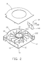
- FIG. 2 is an exploded view of the centrifugal fan of FIG. 1 .
- FIG. 3 is a view similar to FIG. 2 , but shown from a different aspect.
- FIG. 4 is an enlarged view of a tongue of the centrifugal fan of FIG. 2 .
- FIG. 5 is an isometric view of a tongue in accordance with a second embodiment.
- FIG. 6 is an isometric view of a tongue in accordance with a third embodiment.
- FIG. 7 is an isometric view of a related centrifugal fan.
- the centrifugal fan includes a casing 10 , a cover 11 attached to the casing 10 with an inner space 15 formed therebetween, and a plurality of blades 20 rotatably received in the inner space 15 .
- the blades 20 rotate around an axis X-X along a counterclockwise direction as viewed from FIG. 2 .
- the cover 11 defines a through hole therein functioning as an air inlet 16 of the centrifugal fan.
- the casing 10 includes a flat base plate 12 perpendicular to the rotation axis X-X of the blades 20 , a volute sidewall 13 extending upwardly and perpendicularly from an outer periphery of the base plate 12 , and a tongue 14 attached to an inner surface of the sidewall 13 .
- a volute air channel 18 is formed between outmost ends of the blades 20 and the inner surface of the sidewall 13 .
- the sidewall 13 defines an opening in a right side thereof functioning as an air outlet 17 of the centrifugal fan.
- a first locking unit includes two rectangular grooves 132 being defined in a rear side of the sidewall 13 adjacent to the air outlet 17 as viewed in FIG. 2 .
- the two grooves 132 are parallel to each other.
- Each of the grooves 132 extends along a longitudinal direction through the base plate 12 of the casing 10 .
- the tongue 14 is made of porous, acoustic absorbing material, such as foamed plastic, glass wool or fibers.
- the tongue 14 includes an elongated body 140 and a second locking unit.
- the body 140 has a curved guiding surface 143 and an opposite connecting surface 144 .
- the connecting surface 144 of the body 140 is matched with a portion of the inner surface of the sidewall 13 at the first locking unit.
- the second locking unit includes two mounting columns 142 formed on the connecting surface 144 of the body 140 .
- Each mounting column 142 includes a rectangular pole portion 1421 extending along a height direction of the body 140 , and a cap portion 1423 formed on a distal side of the pole portion 1421 away from the connecting surface 144 .
- the pole portions 1421 are parallel to each other. Each of the pole portions 1421 has a shape and size substantially equal to those of each of the grooves 132 of the sidewall 13 ; thus, the pole portions 1421 can be fittingly received in the grooves 132 , respectively.
- the cap portions 1423 also extend along the height direction of the body 140 .
- Each of the cap portions 1423 has a width slightly larger than that of each of the pole portions 1421 , which makes a cross-section of each of the mounting columns 142 approximately T-shaped.
- a pressing surface 1425 parallel to the connecting surface 144 of the body 140 is formed between the cap portion 1423 and the pole portion 1421 of each mounting column 142 .
- the connecting surface 144 of the tongue 14 tightly contacts the inner surface of the sidewall 13 after the tongue 14 and the sidewall 13 are assembled together.
- the guiding surface 143 is a convex surface, and protrudes outwardly from the connecting surface 144 towards the outmost ends of the blades 20 .
- a crested bulge 145 is formed on a middle portion of the guiding surface 143 .
- a thickness of the body 140 decreases gradually from the bulge 145 to two opposite ends (i.e., inner end in the space 15 and outer end adjacent to the air outlet 17 ) of the body 140 along a lengthwise direction of the body 140 , and decreases gradually from the bulge 145 to top and bottom sides of the body 140 along the height direction of the body 140 .
- the distance between the guiding surface 143 of the body 140 and the outmost ends of the blades 20 thus gradually decreases from the inner end of the body 140 towards the bulge 145 , and then gradually increases from the bulge 145 towards the outer end of the body 140 adjacent the air outlet 17 . That is, a minimum distance between the guiding surface 143 and the outmost ends of the blades 20 is formed between the bulge 145 and the outmost ends of the blades 20 .
- the tongue 14 is detachably mounted to the sidewall 13 via the second locking unit and the first locking unit interlocked together.
- the tongue 14 is first placed at a top side of the casing 10 , with bottom ends of the pole portions 1421 aligned with top ends of grooves 132 . Then the tongue 14 is pressed downwardly until the pole portions 1421 are wholly received in the grooves 132 respectively. Meanwhile, the bottom side of the body 140 abuts the base plate 12 , and the connecting surface 144 of the body 140 attaches to the inner surface of the sidewall 13 .
- Each cap portion 1423 protrudes out of the groove 132 with the pressing surfaces 1425 tightly contacted an outer surface of the sidewall 13 .
- the tongue 14 is securely mounted to the sidewall 13 , with the connecting surface 144 of the body 140 contacting the inner surface of the sidewall 13 , and the guiding surface 143 of the body 140 away from the sidewall 13 and facing the outmost ends of the blades 20 .
- the tongue 14 can be disassembled from the sidewall 13 by moving the body 140 upwardly when required.
- the blades 20 rotate along the counterclockwise direction to drive a radial airflow.
- the radial airflow can be exhausted to an outside via the air outlet 17 with higher dynamic and static pressures by passing through the air channel 18 .
- the airflow flows first to the guiding surface 143 of the tongue 14 , then along the air channel 18 and finally to the outside of the centrifugal fan via the air outlet 17 .
- each blown point is a sound source that generates a narrow band noise.
- the guiding surface 143 of the tongue 14 is curved, a distance between each point of the guiding surface 143 of the body 140 and the axis X-X is different from each other, whereby the time at which each noise is generated is different.
- the narrow band noises have different frequencies. Therefore, the noises will not be superposed to generate a noise with a large amplitude. That is, the noise level generated by the airflow blowing on the sidewall 13 near the air outlet 17 is lessened.
- the tongue 14 is made of porous, acoustic absorbing material, which can absorb a portion of the resonant sound waves of the noises, thus reducing the amplitude of the superposed noise more effectively.
- the tongue 14 is detachably connected with the sidewall 13 of the casing 10 , which can be formed from different materials having high sound absorption coefficients to satisfy the special needs of the centrifugal fan according to different requirements. Hence, a lower noise level is obtained to allow the centrifugal fan to operate quietly.
- FIG. 5 illustrates a tongue 14 a according to a second embodiment, differing from the tongue 14 of the first embodiment in that a guiding surface 143 a of a body 140 a of the tongue 14 a is a tapered convex surface, and the thickness of the body 140 a increases gradually along a top-to-bottom direction of the tongue 14 a .
- the guiding surface 143 a of the tongue 14 a includes a concave surface 1431 a extending outwardly from the inner end of the body 140 a , an arced angle 145 a extending outwardly from an outer edge of the concave surface 1431 a , and an inclined planar surface 1432 a extending outwardly from an outer edge of the arced angle 145 a of the body 140 a towards the outer end of the body 140 a adjacent the air outlet 17 .
- the thickness of the tongue 14 a decreases from the arced angle 145 a towards the inner and outer ends of the body 140 a along the lengthwise direction of the body 140 a .
- the arced angle 145 a has a thickness that increases along the top-to-bottom direction of the body 140 a .
- the minimum distance between the guiding surface 143 a of the tongue 14 a and the outmost ends of the blades 20 a is formed between a bottommost end of the arced angle 145 a and the outmost ends of the blades 20 .
- FIG. 6 illustrates a tongue 14 b according to a third embodiment, differing from the tongue 14 a of the second embodiment in that a guiding surface 143 b of a body 140 b of the tongue 14 b is a tapered convex surface with two slots 146 b defined therein along the lengthwise direction of the guiding surface 143 b .
- the guiding surface 143 b of the tongue 14 b includes three concave surfaces 1431 b extending outwardly from the inner end of the body 140 b , three arced angles 145 b extending outwardly from outer edges of the three concave surfaces 1431 b , respectively, and three inclined planar surfaces 1432 b extending outwardly from outer edges of the three arced angles 145 b , respectively, to the outer end of the body 140 b adjacent the air outlet 17 .
- Each slot 146 b is defined between two neighboring concave surfaces 1431 b and the corresponding two arced angles 145 b and the corresponding two inclined planar surfaces 1432 b .
- the thickness of the tongue 14 b decreases from the arced angles 145 b to the inner and outer ends of the body 140 b along the lengthwise direction. In addition, the thickness of the tongue 14 b increases along the top-to-bottom direction of the body 140 b .
- the minimum distance between the guiding surface 143 b of the tongue 14 b and the outmost ends of the blades 20 is formed between a bottommost arced angle 145 b and the outmost ends of the blades 20 .
Abstract
Description
Claims (14)
Applications Claiming Priority (3)
| Application Number | Priority Date | Filing Date | Title |
|---|---|---|---|
| CN200810303725.2 | 2008-08-13 | ||
| CN200810303725 | 2008-08-13 | ||
| CN200810303725.2A CN101649845B (en) | 2008-08-13 | 2008-08-13 | Centrifugal fan |
Publications (2)
| Publication Number | Publication Date |
|---|---|
| US20100040456A1 US20100040456A1 (en) | 2010-02-18 |
| US8083477B2 true US8083477B2 (en) | 2011-12-27 |
Family
ID=41672146
Family Applications (1)
| Application Number | Title | Priority Date | Filing Date |
|---|---|---|---|
| US12/328,782 Expired - Fee Related US8083477B2 (en) | 2008-08-13 | 2008-12-05 | Centrifugal fan |
Country Status (2)
| Country | Link |
|---|---|
| US (1) | US8083477B2 (en) |
| CN (1) | CN101649845B (en) |
Cited By (14)
| Publication number | Priority date | Publication date | Assignee | Title |
|---|---|---|---|---|
| US20100092282A1 (en) * | 2008-10-13 | 2010-04-15 | Furui Precise Component (Kunshan) Co., Ltd. | Centrifugal fan |
| US20100104421A1 (en) * | 2008-10-23 | 2010-04-29 | Foxconn Technology Co., Ltd. | Cooling fan |
| US20120026677A1 (en) * | 2010-07-29 | 2012-02-02 | Gurmeet Bhutani | Dual operation centrifugal fan apparatus and methods of using same |
| US20130272862A1 (en) * | 2012-04-12 | 2013-10-17 | Foxconn Technology Co., Ltd. | Method for manufacturing fan blade and fan using such fan blades |
| US8678131B2 (en) * | 2012-03-30 | 2014-03-25 | Textron Innovations Inc. | Acoustic baffle for centrifugal blowers |
| US20140154067A1 (en) * | 2012-12-03 | 2014-06-05 | Hon Hai Precision Industry Co., Ltd. | Electronic device assembly with fan |
| US8813908B1 (en) * | 2013-03-08 | 2014-08-26 | Ford Global Technologies, Llc | HVAC blower with noise suppression features |
| US20150198178A1 (en) * | 2012-09-03 | 2015-07-16 | Sanden Corporation | Centrifugal air blower |
| US20160209893A1 (en) * | 2015-01-21 | 2016-07-21 | Lenovo (Beijing) Co., Ltd. | Centrifugal Fan and an Electronic Device Having the Same |
| US9997971B2 (en) | 2012-12-18 | 2018-06-12 | Spal Automotive S.R.L. | Electrical machine |
| US20180298914A1 (en) * | 2015-04-28 | 2018-10-18 | Denso Corporation | Blower |
| US10816011B2 (en) | 2018-07-18 | 2020-10-27 | Cooler Master Co., Ltd. | Fan housing with metal foam and fan having the fan housing |
| US11506222B2 (en) | 2018-09-25 | 2022-11-22 | Carrier Corporation | Fan housing, fan and operating system having a fan |
| US20240044340A1 (en) * | 2022-08-02 | 2024-02-08 | Techtronic Cordless Gp | Inflator having combined cutwater and intake/exhaust port |
Families Citing this family (24)
| Publication number | Priority date | Publication date | Assignee | Title |
|---|---|---|---|---|
| JP5629505B2 (en) | 2010-06-25 | 2014-11-19 | 山洋電気株式会社 | Centrifugal fan |
| US9334876B2 (en) * | 2011-04-12 | 2016-05-10 | Thermo Neslab Inc. | Pump casing and related apparatus and methods |
| CN102758798A (en) * | 2011-04-26 | 2012-10-31 | 嵊州市龙马冲件有限公司 | Fan device with noise reducing structure |
| US9121638B2 (en) * | 2012-03-26 | 2015-09-01 | Dri-Eaz Products, Inc. | Surface dryers producing uniform exit velocity profiles, and associated systems and methods |
| ITBO20120298A1 (en) * | 2012-05-31 | 2013-12-01 | Spal Automotive Srl | VENTILATION UNIT. |
| CN103511347B (en) * | 2012-06-19 | 2015-12-02 | 奇鋐科技股份有限公司 | Fan structure |
| KR102143389B1 (en) * | 2013-03-20 | 2020-08-28 | 삼성전자주식회사 | Circular Fan and Air Conditioner Having the Same |
| CN110863999A (en) | 2013-06-28 | 2020-03-06 | 施耐德电气It公司 | Cooling rack fan module and cooling method |
| USD761950S1 (en) * | 2013-07-10 | 2016-07-19 | Dri-Eaz Products, Inc. | Air dryer |
| TWI537477B (en) | 2013-07-25 | 2016-06-11 | 華碩電腦股份有限公司 | Fan blade structure and centrifugal blower using the same |
| US9915271B2 (en) * | 2015-01-20 | 2018-03-13 | Ford Global Technologies, Llc | Blower assembly for a vehicle |
| CN105221484A (en) * | 2015-09-21 | 2016-01-06 | 联想(北京)有限公司 | Radiation fan |
| US10415601B2 (en) * | 2017-07-07 | 2019-09-17 | Denso International America, Inc. | Blower noise suppressor |
| CN107448420A (en) * | 2017-08-03 | 2017-12-08 | 广东美的厨房电器制造有限公司 | Smoke evacuation component and range hood |
| CN108412800A (en) * | 2018-05-25 | 2018-08-17 | 绍兴智新机电科技有限公司 | A kind of extraordinary wind turbine of explosion-proof noise elimination |
| CN108869405B (en) * | 2018-06-05 | 2020-08-14 | 广东海信家电有限公司 | Double-air-inlet centrifugal fan and range hood |
| CN108931043B (en) * | 2018-10-24 | 2023-09-15 | 奥克斯空调股份有限公司 | Air duct structure and air conditioner |
| US11236759B2 (en) | 2018-10-29 | 2022-02-01 | Legend Brands, Inc. | Contoured fan blades and associated systems and methods |
| EP3954902A4 (en) * | 2019-04-12 | 2022-11-02 | Qingdao Haier Drum Washing Machine Co., Ltd. | Housing of centrifugal fan, centrifugal fan and clothes dryer |
| CN113280004B (en) * | 2020-02-20 | 2023-08-22 | 宏碁股份有限公司 | Heat radiation fan |
| CN114198321B (en) * | 2021-12-03 | 2023-10-27 | 合肥联宝信息技术有限公司 | Centrifugal fan with self-adaptive runner |
| CN114607644B (en) * | 2022-04-01 | 2023-11-03 | 石家庄东方热电热力工程有限公司 | Heat radiation unit for electric device |
| EP4321760A1 (en) * | 2022-08-09 | 2024-02-14 | Regal Beloit America, Inc. | Interchangeable modular cutoff for centrifugal blowers |
| GB2622050A (en) * | 2022-08-31 | 2024-03-06 | Dyson Technology Ltd | A volute for a turbomachine |
Citations (7)
| Publication number | Priority date | Publication date | Assignee | Title |
|---|---|---|---|---|
| US3695775A (en) * | 1969-10-10 | 1972-10-03 | Kurt Dr Ing Zenkner | Cross flow blower |
| US5108833A (en) * | 1988-10-31 | 1992-04-28 | Mitsubishi Denki Kabushiki Kaisha | Porous structural unit and a method of preparing the same |
| US5110258A (en) * | 1989-08-09 | 1992-05-05 | Mitsubishi Denki Kabushiki Kaisha | Blower having a sound-damping structure |
| US5997246A (en) * | 1998-04-02 | 1999-12-07 | Ford Motor Company | Housing for a centrifugal blower |
| US6463230B1 (en) * | 2001-08-20 | 2002-10-08 | Xerox Corporation | Office machine including a blower having a blower noise reducing device |
| US7210903B2 (en) * | 2004-09-03 | 2007-05-01 | Fasco Industries, Inc. | Lobed joint draft inducer blower |
| US20080107523A1 (en) * | 2005-01-27 | 2008-05-08 | Delta Electronics Inc. | Blower |
Family Cites Families (7)
| Publication number | Priority date | Publication date | Assignee | Title |
|---|---|---|---|---|
| SU1536068A1 (en) * | 1986-05-21 | 1990-01-15 | Предприятие П/Я М-5356 | Scroll of centrifugal pump |
| CN1186535C (en) * | 2001-08-08 | 2005-01-26 | 台达电子工业股份有限公司 | Side-blowing typeradiation device |
| CN100350348C (en) * | 2004-04-26 | 2007-11-21 | 广达电脑股份有限公司 | Centrifugal fan |
| US7329095B2 (en) * | 2004-10-08 | 2008-02-12 | Asia Vital Component Co., Ltd. | Blower capable of reducing secondary flow |
| CN2755321Y (en) * | 2004-11-22 | 2006-02-01 | 广达电脑股份有限公司 | Centrifugal fan |
| CN100531538C (en) * | 2006-06-02 | 2009-08-19 | 富准精密工业(深圳)有限公司 | Heat radiating device |
| CN101126396A (en) * | 2007-09-18 | 2008-02-20 | 苏州华盛风机厂 | Low noise ventilator |
-
2008
- 2008-08-13 CN CN200810303725.2A patent/CN101649845B/en not_active Expired - Fee Related
- 2008-12-05 US US12/328,782 patent/US8083477B2/en not_active Expired - Fee Related
Patent Citations (7)
| Publication number | Priority date | Publication date | Assignee | Title |
|---|---|---|---|---|
| US3695775A (en) * | 1969-10-10 | 1972-10-03 | Kurt Dr Ing Zenkner | Cross flow blower |
| US5108833A (en) * | 1988-10-31 | 1992-04-28 | Mitsubishi Denki Kabushiki Kaisha | Porous structural unit and a method of preparing the same |
| US5110258A (en) * | 1989-08-09 | 1992-05-05 | Mitsubishi Denki Kabushiki Kaisha | Blower having a sound-damping structure |
| US5997246A (en) * | 1998-04-02 | 1999-12-07 | Ford Motor Company | Housing for a centrifugal blower |
| US6463230B1 (en) * | 2001-08-20 | 2002-10-08 | Xerox Corporation | Office machine including a blower having a blower noise reducing device |
| US7210903B2 (en) * | 2004-09-03 | 2007-05-01 | Fasco Industries, Inc. | Lobed joint draft inducer blower |
| US20080107523A1 (en) * | 2005-01-27 | 2008-05-08 | Delta Electronics Inc. | Blower |
Cited By (21)
| Publication number | Priority date | Publication date | Assignee | Title |
|---|---|---|---|---|
| US8251642B2 (en) * | 2008-10-13 | 2012-08-28 | Furui Precise Component (Kunshan) Co., Ltd. | Centrifugal fan |
| US20100092282A1 (en) * | 2008-10-13 | 2010-04-15 | Furui Precise Component (Kunshan) Co., Ltd. | Centrifugal fan |
| US20100104421A1 (en) * | 2008-10-23 | 2010-04-29 | Foxconn Technology Co., Ltd. | Cooling fan |
| US8403633B2 (en) * | 2008-10-23 | 2013-03-26 | Foxconn Technology Co., Ltd. | Cooling fan |
| US20120026677A1 (en) * | 2010-07-29 | 2012-02-02 | Gurmeet Bhutani | Dual operation centrifugal fan apparatus and methods of using same |
| US11022131B2 (en) | 2010-07-29 | 2021-06-01 | Dell Products L.P. | Dual operation centrifugal fan apparatus and methods of using same |
| US9845805B2 (en) * | 2010-07-29 | 2017-12-19 | Dell Products, L.P. | Dual operation centrifugal fan apparatus and methods of using same |
| US9279358B2 (en) | 2012-03-30 | 2016-03-08 | Textron Innovations, Inc. | Acoustic baffle for centrifugal blowers |
| US8678131B2 (en) * | 2012-03-30 | 2014-03-25 | Textron Innovations Inc. | Acoustic baffle for centrifugal blowers |
| US20130272862A1 (en) * | 2012-04-12 | 2013-10-17 | Foxconn Technology Co., Ltd. | Method for manufacturing fan blade and fan using such fan blades |
| US20150198178A1 (en) * | 2012-09-03 | 2015-07-16 | Sanden Corporation | Centrifugal air blower |
| US10066642B2 (en) * | 2012-09-03 | 2018-09-04 | Sanden Holdings Corporation | Centrifugal air blower |
| US20140154067A1 (en) * | 2012-12-03 | 2014-06-05 | Hon Hai Precision Industry Co., Ltd. | Electronic device assembly with fan |
| US9997971B2 (en) | 2012-12-18 | 2018-06-12 | Spal Automotive S.R.L. | Electrical machine |
| US8813908B1 (en) * | 2013-03-08 | 2014-08-26 | Ford Global Technologies, Llc | HVAC blower with noise suppression features |
| US20160209893A1 (en) * | 2015-01-21 | 2016-07-21 | Lenovo (Beijing) Co., Ltd. | Centrifugal Fan and an Electronic Device Having the Same |
| US9933824B2 (en) * | 2015-01-21 | 2018-04-03 | Lenovo (Beijing) Co., Ltd. | Centrifugal fan and an electronic device having the same |
| US20180298914A1 (en) * | 2015-04-28 | 2018-10-18 | Denso Corporation | Blower |
| US10816011B2 (en) | 2018-07-18 | 2020-10-27 | Cooler Master Co., Ltd. | Fan housing with metal foam and fan having the fan housing |
| US11506222B2 (en) | 2018-09-25 | 2022-11-22 | Carrier Corporation | Fan housing, fan and operating system having a fan |
| US20240044340A1 (en) * | 2022-08-02 | 2024-02-08 | Techtronic Cordless Gp | Inflator having combined cutwater and intake/exhaust port |
Also Published As
| Publication number | Publication date |
|---|---|
| CN101649845A (en) | 2010-02-17 |
| US20100040456A1 (en) | 2010-02-18 |
| CN101649845B (en) | 2013-02-20 |
Similar Documents
| Publication | Publication Date | Title |
|---|---|---|
| US8083477B2 (en) | Centrifugal fan | |
| US8403633B2 (en) | Cooling fan | |
| US20100071875A1 (en) | Heat dissipation device and centrifugal fan thereof | |
| US8113766B2 (en) | Fan and fan frame thereof | |
| US8251642B2 (en) | Centrifugal fan | |
| US7284952B2 (en) | Centrifugal fan | |
| US9322408B2 (en) | Centrifugal fan | |
| US8267158B2 (en) | Thermal module | |
| US7329091B2 (en) | Heat dissipation fans and housings therefor | |
| US8100664B2 (en) | Impeller for a cooling fan | |
| US20110176916A1 (en) | Centrifugal fan and impeller thereof | |
| US20060099071A1 (en) | Centrifugal fan | |
| US8240989B2 (en) | Fan | |
| US9518584B2 (en) | Centrifugal fan with ancillary airflow opening | |
| US20050276684A1 (en) | Centrifugal fan with resonant silencer | |
| US8100642B2 (en) | Centrifugal blower | |
| US8342799B2 (en) | Centrifugal fan | |
| US9523375B2 (en) | Fan blade structure and centrifugal fan using the same | |
| US20090290306A1 (en) | Heat dissipating assembly and electronic device having same | |
| US20100059210A1 (en) | Fan impeller and heat dissipating device having the same | |
| US20150110615A1 (en) | Centrifugal fan | |
| US9145895B2 (en) | Heat dissipation fan | |
| US20090010757A1 (en) | Centrifugal blower | |
| US7542275B2 (en) | Computer case | |
| US20090060730A1 (en) | Centrifugal fan and impeller thereof |
Legal Events
| Date | Code | Title | Description |
|---|---|---|---|
| AS | Assignment |
Owner name: FURUI PRECISE COMPONENT (KUNSHAN) CO., LTD.,CHINA Free format text: ASSIGNMENT OF ASSIGNORS INTEREST;ASSIGNORS:HWANG, CHING-BAI;ZHAO, ZHI-HUI;REEL/FRAME:021928/0322 Effective date: 20081128 Owner name: FOXCONN TECHNOLOGY CO., LTD.,TAIWAN Free format text: ASSIGNMENT OF ASSIGNORS INTEREST;ASSIGNORS:HWANG, CHING-BAI;ZHAO, ZHI-HUI;REEL/FRAME:021928/0322 Effective date: 20081128 Owner name: FOXCONN TECHNOLOGY CO., LTD., TAIWAN Free format text: ASSIGNMENT OF ASSIGNORS INTEREST;ASSIGNORS:HWANG, CHING-BAI;ZHAO, ZHI-HUI;REEL/FRAME:021928/0322 Effective date: 20081128 Owner name: FURUI PRECISE COMPONENT (KUNSHAN) CO., LTD., CHINA Free format text: ASSIGNMENT OF ASSIGNORS INTEREST;ASSIGNORS:HWANG, CHING-BAI;ZHAO, ZHI-HUI;REEL/FRAME:021928/0322 Effective date: 20081128 |
|
| REMI | Maintenance fee reminder mailed | ||
| LAPS | Lapse for failure to pay maintenance fees | ||
| STCH | Information on status: patent discontinuation |
Free format text: PATENT EXPIRED DUE TO NONPAYMENT OF MAINTENANCE FEES UNDER 37 CFR 1.362 |
|
| FP | Lapsed due to failure to pay maintenance fee |
Effective date: 20151227 |