US8079416B2 - Plug for a perforated liner and method of using same - Google Patents
Plug for a perforated liner and method of using same Download PDFInfo
- Publication number
- US8079416B2 US8079416B2 US12/506,744 US50674409A US8079416B2 US 8079416 B2 US8079416 B2 US 8079416B2 US 50674409 A US50674409 A US 50674409A US 8079416 B2 US8079416 B2 US 8079416B2
- Authority
- US
- United States
- Prior art keywords
- liner
- plug
- extendible portions
- base portion
- extendible
- Prior art date
- Legal status (The legal status is an assumption and is not a legal conclusion. Google has not performed a legal analysis and makes no representation as to the accuracy of the status listed.)
- Expired - Fee Related, expires
Links
Images


Classifications
-
- E—FIXED CONSTRUCTIONS
- E21—EARTH DRILLING; MINING
- E21B—EARTH DRILLING, e.g. DEEP DRILLING; OBTAINING OIL, GAS, WATER, SOLUBLE OR MELTABLE MATERIALS OR A SLURRY OF MINERALS FROM WELLS
- E21B43/00—Methods or apparatus for obtaining oil, gas, water, soluble or meltable materials or a slurry of minerals from wells
- E21B43/11—Perforators; Permeators
-
- E—FIXED CONSTRUCTIONS
- E21—EARTH DRILLING; MINING
- E21B—EARTH DRILLING, e.g. DEEP DRILLING; OBTAINING OIL, GAS, WATER, SOLUBLE OR MELTABLE MATERIALS OR A SLURRY OF MINERALS FROM WELLS
- E21B33/00—Sealing or packing boreholes or wells
- E21B33/10—Sealing or packing boreholes or wells in the borehole
- E21B33/12—Packers; Plugs
-
- E—FIXED CONSTRUCTIONS
- E21—EARTH DRILLING; MINING
- E21B—EARTH DRILLING, e.g. DEEP DRILLING; OBTAINING OIL, GAS, WATER, SOLUBLE OR MELTABLE MATERIALS OR A SLURRY OF MINERALS FROM WELLS
- E21B43/00—Methods or apparatus for obtaining oil, gas, water, soluble or meltable materials or a slurry of minerals from wells
- E21B43/12—Methods or apparatus for controlling the flow of the obtained fluid to or in wells
Definitions
- This invention relates generally to an apparatus and its use in plugging perforated liners such as those that may be used in wellbores and other installations.
- a liner which is often a steel or other alloy pipe or tubular
- the space or annulus between the face of the formation and the liner may be packed with sand, gravel or other material.
- the liner is cemented in place through pumping cement or a cementatous-type material into the annulus. Upon setting, the cement serves to stabilize the position of the liner within the wellbore, helps to prevent a collapse, sloughing and cracking of the exposed formation face and can further help to prevent the escape of fluids from the formation.
- cementing the liner in place can help to prevent the release of water from the formation into the well. In other instances cementing of the liner will help prevent the release of gas where the well passes through formations that harbour pressurized gas. Where there are multiple zones that are targeted for the production of fluid, in some instances it may be desirable to seal off particular zones through cementing the liner in place to permit the controlled and systematic release of fluid from particular zones in a particular sequence.
- a liner typically has been cemented within a production zone once the cement has hardened and cured the well is reentered in order to perforate the liner and to allow for the extraction of production fluid.
- a variety of mechanisms and techniques have been developed in order to perforate a liner, most of which involve the lowering of a perforating gun into the tubular and using the gun to perforate the liner or well casing.
- Such guns typically utilize shaped charges that produce holes within the side of the liner having a relatively consistent size and shape.
- Others have proposed various other mechanical devices to punch or drill holes in liners once they are in place.
- Still others have devised liners themselves that are pre-fitted with small explosive charges that can be detonated after the liner has been connected in place in order to perforate a particular zone or section of the liner.
- liners are pre-drilled at the surface with solid aluminium or similar plugs inserted into the holes, following which the liner is lowered and placed into position within the well.
- the liner can be cemented in place, with the plugs retaining the cement slurry within the annulus formed between the formation face and the exterior surface of the liner.
- the plugs can then be removed, effectively creating a perforated liner. Removal of the plugs can be achieved mechanically, ultrasonically, or through packing off the section of the liner in question and introducing an acid to dissolve the material from which the plugs are made.
- the invention therefore provides a plug for a perforated liner and a method of using such a plug that addresses a number of the deficiencies in the structures and methods that are currently in use.
- the invention provides a plug for insertion into a perforation in a liner or tubular, the plug comprising a base portion and one or more extendible portions, said base portion securable to and receivable within said perforation said base portion and said one or more extendible portions sealing the perforation in said liner, said one or more extendible portions having a retracted position and an extended position such that when in said extended position said one or more extendible portions extend outwardly from said base portion and outwardly from the exterior surface of said liner.
- the invention provides a plug for insertion into a perforation in a liner or tubular, the plug comprising a base portion securable to and received within a perforation in said liner, the plug further comprising one or more extendible portions having a retracted position and an extended position, when in said extended position said one or more extendible portions extending outwardly from said base portion and outwardly from the exterior surface of said liner, said base portion and said one or more extendible portions together sealing the perforation in said liner.
- the invention also concerns a method of using and deploying a plug for insertion into a perforation in a liner or tubular to be inserted into a bore hole, the plug comprising a base portion and one or more extendible portions, said base portion securable to and receivable within the perforation, said one or more extendible portions having a retracted position and an extended position, said one or more extendible portions extending outwardly from said base portion and outwardly from the exterior surface of said liner when in said extended positions, the method comprising:
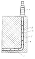
- FIG. 1 is a vertical sectional view through a wellbore that has been lined with a perforated liner wherein the perforations are enclosed with plugs in accordance with one of the preferred embodiments of the present invention
- FIG. 2 is an enlarged sectional view of a lined borehole wherein the liner has plugs in accordance with one of the preferred embodiments of the invention inserted within perforations;
- FIG. 3 is a Figure similar to FIG. 2 wherein the borehole is cased
- FIG. 4 is an enlarged sectional view of a borehole having a perforated liner with plugs in accordance with one of the preferred embodiments of the invention inserted within the perforations and wherein the plugs are generally flush with the exterior surface of the liner;
- FIG. 5 is a view similar to FIG. 4 wherein the plugs are in an extended position
- FIG. 6 is an enlarged sectional view of the plugs shown in FIG. 4 ;
- FIG. 7 is a view of the plug shown in FIG. 6 in a partially deployed position
- FIG. 8 a view of the plug shown in FIG. 6 in a fully deployed position
- FIG. 9 is a view similar to FIG. 8 wherein the plug is in a deployed position
- FIG. 10 is an enlarged sectional view of an alternate embodiment of one of the plugs shown in FIG. 4 ;
- FIG. 11 is an enlarged sectional view of the plug shown in FIG. 10 in its fully deployed position.
- FIG. 1 With reference to FIG. 1 there is shown a vertical section through a typical borehole 1 extending from a surface rig 2 into an underground formation 3 .
- the configuration and nature of the borehole can vary substantially from application to application.
- the borehole may have a horizontal section.
- the borehole may be cased or uncased, however, the particular configuration and structure of the borehole does not affect the invention.
- the borehole is lined with a liner 4 having perforations.
- the perforations have plugs 6 , constructed in accordance with the present invention, inserted therein.
- plug 6 is comprised generally of a base portion 7 and one or more extendible portions 8 .
- the base portion is securable to and receivable within the perforations in liner 4 .
- the base portion together with the one or more extendible portions, seal the perforation.
- the extendible portions have a retracted position and an extended position such that when they are in their retracted position the outer surface of the plug is generally flush with the exterior surface of the liner. When the extendible portions are in their extended position they extend outwardly from the base portion and outwardly from the exterior surface of the liner.
- base portion 7 and extendible portions 8 are formed from circular, cylindrical members that are nested and concentric such that the extendible portions are telescopically received within the base portion.
- the precise geometric configuration and shape of both the base portion and the extendible portions could vary while remaining within the broad scope of the invention.
- the cross-section of the extendible portions could be rectangular, hexagonal, octagonal or any one of a wide variety of other geometric shapes.
- base portion 7 could also take on a variety of different geometric shapes.
- Plug 6 further include seals 9 positioned between adjacent cylindrical members such that when the base portion is received within a perforation the base, in combination with the extendible portions and seals 9 , serves to seal the perforation
- seals 9 are O-rings, however, it will also be appreciated by those skilled in the art that various other seals could equally be utilized.
- threads 10 to permit it to be threaded into the perforation within liner 4 .
- FIGS. 6 through 9 show one of the preferred structures that may form base portion 7 and extendible portions 8 .
- the extendible portions have an outwardly oriented flange 11 on their inner ends 12 and an inwardly oriented shoulder 13 on their outer ends 14 .
- An inwardly extending shoulder 15 about the outer edge 16 of base portion 7 retains the nested and telescopic extendible portions within the confines of the plug.
- O-ring seals 9 between adjacent cylindrical members presents a fluid tight seal between the various parts of plug 6 .
- the central extendible portion 17 is in the form of a cylindrical member having an annular flange 18 on its inner end 19 .
- the outer end 20 of the central extendible portion 17 will be enclosed and generally flat to permit it to engage the interior surface of borehole 1 or the interior surface of the liner if the borehole is lined.
- plug 6 Through construction of plug 6 in accordance with the preferred embodiment shown in the attached drawings and as described above, deployment of the plug such that the extendible portions are moved from their retracted to extend positions can be accomplished by pressurizing the interior of liner 4 .
- the sealing of base portion 7 within the perforation and the use of seals at 9 between adjacent cylindrical members allows the plug to retain pressurized fluid within the liner, forcing the telescopically nested extendible portions to be driven outwardly until either the annular flange 19 on the central extendible portion 17 is driven up against the outer shoulder 13 on the next adjacent extendible portion (see FIG. 8 ), or until the outer end 20 of the central extendible portion 17 comes into contact with either the borehole wall (see FIG.
- the extendible portions will be accomplished through packing off a section of the liner and injecting pressurized air or gas into that section. Alternately, the extendible portions may be deployed through pressurizing the liner with a wide variety of other fluids.
- a plurality of plugs 6 are inserted into perforations in a section of liner.
- the plugs are threaded into the perforations, however, in alternate embodiments the plugs could also be secured in place through the use of glues or adhesives, through welding, or through press fitting or any other commonly used means.
- the extendible portions 8 will be in their retracted position and held roughly in those positions through the interaction of the O-ring seals with adjacent cylindrical portions.
- the perforated portion of the liner can then be inserted into a well or borehole and positioned at its desired location.
- the interior of the liner is pressurized causing the extendible portions 8 to move from their retracted to their extended positions, at which point the outer ends 20 of central extendible portions 17 will be in contact with (or in close proximity to) the borehole wall.
- cementing operations can commence where the annulus between the liner and the wellbore is filled or injected with cement or a cementatous-type material. Once the cement or cementatous-type material has hardened or cured, at least the extendible portions of the plugs are destroyed, leaving the liner cemented in place, while at the same time providing access to the face of the bore hole through the perforations in the liner.
- Destruction of the extendible portions can be accomplished through a variety of different mechanisms.
- the extendible portions are constructed from material that dissolves when exposed to acid and the destruction of the extendible portions involves exposing the plugs to an acidic solution for a sufficient length of time to dissolve at least the extendible portions of the plugs. This process would typically be accomplished through packing off the liner and delivering the acidic solution by running coiled tubing into the well.
- the extendible portions (and for that matter the base portion as well if desired) can be formed from an aluminium alloy which can be dissolved through subjecting to an acid.
- the extendible portions could be constructed from a variety of plastics or other materials.
- the extendible portions can be constructed from materials that can be destroyed or pulverized and the destruction of the extendible portions could be accomplished through subjecting them to the blast from the detonation of a charge, through drilling, through mechanical impact, or through sonic or ultra-sonic vibration.
- FIGS. 10 and 11 An alternate embodiment of plug 6 is shown in FIGS. 10 and 11 .
- the plug is constructed generally in accordance with the plug shown in FIGS. 1 through 9 , however, a series of shear pins 100 extend through base portion 7 and extendible portions 8 when the extendible portions are in their retracted position (as specifically shown in FIG. 10 ).
- shear pins 100 when received within correspondingly shaped passageways 101 that extend through base portion 7 and extendible portions 8 , will assist in maintaining the extendible portions in their retracted position until such time as sufficient force is applied to the plug to permit the shearing of pins 100 and the deployment of the extendible portions.
- the shear pins will be constructed of a material and will have dimensions such that they will have a sufficiently high shear strength to retain the extendible portions in their retracted positions when desired, while at the same time having a sufficiently low shear strength that will enable the pins to be sheared by the pressurizing of the interior of liner 4 through the use of conventional equipment.
- the pins 100 may also be sheared through being subjected to mechanical force, through a directed blast force, through ultra sonic vibration or through a variety of other methods.
- Shear pins 100 may be made from a variety of different materials including aluminum, plastics or other materials the same or similar to those from which the base and extendible portions of the plug are formed. Preferably the pins are dissolved, pulverized or otherwise suitably or substantially destroyed at the same time and through the same means that the various other portions of the plug are destroyed. However, in light of their relatively small size, the failure to destroy or completely destroy the pins should have no appreciable affect on the extraction of production fluid from the well after the plugs have been deployed and their extendible portions destroyed or pulverized.
- the use of shear pins 100 will help to maintain and stabilize the plugs in their retracted position during transport of the liner, during insertion into the well, and generally until such time as deployment is desired. The shear pins will also help to prevent the plugs from being driven inwardly into the liner if exposed to external pressure or force. The shear pins are particularly useful in maintaining the plugs in their retracted positions in horizontal well applications.
- plugs 6 within the perforations of a liner will allow for the centralization of the liner within the borehole and also effectively present a tunnel leading from the interior of the liner to the face of the formation once the liner has been cemented in place, and at least the extendible portions of the plug are disintegrated, dissolved or otherwise destroyed.
- the use of such plugs removes the need for subsequently entering the well with perforating guns or other mechanical devices that have previously been used to perforate a liner in situ.
- the plugs of the present invention present the ability to maintain a tunnel or effectively a direct conduit that terminates at the face of the borehole, whereas standard plugs, once dissolved, still require the dissolution or destruction of the cement between the plug and the face of the borehole.
Abstract
Description
-
- (i) inserting said plug into a perforation in the liner or tubular and securing said plug thereto;
- (ii) positioning the liner or tubular at a desired location within a wellbore; and,
- (iii) pressurizing the interior of the liner or tubular to move said one or more extendible portions from said retracted to said extended positions such that they extend outwardly from the exterior surface of said liner.
Claims (13)
Priority Applications (2)
| Application Number | Priority Date | Filing Date | Title |
|---|---|---|---|
| US12/506,744 US8079416B2 (en) | 2009-03-13 | 2009-07-21 | Plug for a perforated liner and method of using same |
| CA2674160A CA2674160C (en) | 2009-03-13 | 2009-07-29 | Plug for a perforated liner and method of using same |
Applications Claiming Priority (2)
| Application Number | Priority Date | Filing Date | Title |
|---|---|---|---|
| US12/403,576 US20100230100A1 (en) | 2009-03-13 | 2009-03-13 | Plug for a Perforated Liner and Method of Using Same |
| US12/506,744 US8079416B2 (en) | 2009-03-13 | 2009-07-21 | Plug for a perforated liner and method of using same |
Related Parent Applications (1)
| Application Number | Title | Priority Date | Filing Date |
|---|---|---|---|
| US12/403,576 Continuation-In-Part US20100230100A1 (en) | 2009-03-13 | 2009-03-13 | Plug for a Perforated Liner and Method of Using Same |
Publications (2)
| Publication Number | Publication Date |
|---|---|
| US20100230103A1 US20100230103A1 (en) | 2010-09-16 |
| US8079416B2 true US8079416B2 (en) | 2011-12-20 |
Family
ID=42729758
Family Applications (1)
| Application Number | Title | Priority Date | Filing Date |
|---|---|---|---|
| US12/506,744 Expired - Fee Related US8079416B2 (en) | 2009-03-13 | 2009-07-21 | Plug for a perforated liner and method of using same |
Country Status (2)
| Country | Link |
|---|---|
| US (1) | US8079416B2 (en) |
| CA (1) | CA2674160C (en) |
Cited By (6)
| Publication number | Priority date | Publication date | Assignee | Title |
|---|---|---|---|---|
| US20110220362A1 (en) * | 2010-03-15 | 2011-09-15 | Baker Hughes Incorporation | Method and Materials for Proppant Flow Control With Telescoping Flow Conduit Technology |
| US20110308803A1 (en) * | 2010-06-16 | 2011-12-22 | Baker Hughes Incorporated | Fracturing Method to Reduce Tortuosity |
| US20140096970A1 (en) * | 2012-10-10 | 2014-04-10 | Baker Hughes Incorporated | Multi-zone fracturing and sand control completion system and method thereof |
| US20140231064A1 (en) * | 2011-10-19 | 2014-08-21 | Ten K Energy Services Ltd. | Insert Assembly for Downhole Perforating Apparatus |
| US20140352979A1 (en) * | 2011-09-13 | 2014-12-04 | Geir Håbesland | Collar |
| US10954776B2 (en) * | 2019-05-28 | 2021-03-23 | Exacta-Frac Energy Services, Inc. | Mechanical casing perforation locator and methods of using same |
Families Citing this family (8)
| Publication number | Priority date | Publication date | Assignee | Title |
|---|---|---|---|---|
| US8826985B2 (en) * | 2009-04-17 | 2014-09-09 | Baker Hughes Incorporated | Open hole frac system |
| EP2761122B1 (en) * | 2011-09-27 | 2016-09-21 | Baker Hughes Incorporated | Method and system for hydraulic fracturing |
| US9605519B2 (en) | 2013-07-24 | 2017-03-28 | Baker Hughes Incorporated | Non-ballistic tubular perforating system and method |
| US9441455B2 (en) | 2013-09-27 | 2016-09-13 | Baker Hughes Incorporated | Cement masking system and method thereof |
| US9410398B2 (en) | 2013-09-27 | 2016-08-09 | Baker Hughes Incorporated | Downhole system having compressable and expandable member to cover port and method of displacing cement using member |
| CN104234647B (en) * | 2014-07-16 | 2017-02-08 | 大庆福斯特科技开发有限公司 | Underground opening self-locking casing centering device |
| GB2557318A (en) * | 2016-12-06 | 2018-06-20 | Maersk Olie & Gas | Methods and apparatus for creating wellbores |
| US10900332B2 (en) | 2017-09-06 | 2021-01-26 | Saudi Arabian Oil Company | Extendable perforation in cased hole completion |
Citations (42)
| Publication number | Priority date | Publication date | Assignee | Title |
|---|---|---|---|---|
| US921337A (en) | 1908-09-24 | 1909-05-11 | William Alexander Archer | Well-screen. |
| US1811235A (en) | 1926-01-15 | 1931-06-23 | Walter E King | Well screen |
| US3425491A (en) | 1966-01-20 | 1969-02-04 | Zanal Corp Of Alberta Ltd | Filter means for duct-forming devices |
| US3429512A (en) | 1966-10-20 | 1969-02-25 | Bodine Albert G | Sonic method and apparatus for grinding rock material and the like to powder |
| US3645563A (en) * | 1969-05-07 | 1972-02-29 | Brown & Root | Method and apparatus for making submerged pipeline connections |
| US4103739A (en) * | 1976-09-03 | 1978-08-01 | Hall L D | Sand release apparatus for a pump |
| US4285398A (en) | 1978-10-20 | 1981-08-25 | Zandmer Solis M | Device for temporarily closing duct-formers in well completion apparatus |
| US4519451A (en) * | 1983-05-09 | 1985-05-28 | Otis Engineering Corporation | Well treating equipment and methods |
| US4688486A (en) * | 1983-12-27 | 1987-08-25 | Thomson Brandt Armements | Multi-head military charge |
| US5165478A (en) | 1991-09-16 | 1992-11-24 | Conoco Inc. | Downhole activated process and apparatus for providing cathodic protection for a pipe in a wellbore |
| US5228518A (en) * | 1991-09-16 | 1993-07-20 | Conoco Inc. | Downhole activated process and apparatus for centralizing pipe in a wellbore |
| US5425424A (en) | 1994-02-28 | 1995-06-20 | Baker Hughes Incorporated | Casing valve |
| US5492173A (en) * | 1993-03-10 | 1996-02-20 | Halliburton Company | Plug or lock for use in oil field tubular members and an operating system therefor |
| US6119776A (en) | 1998-02-12 | 2000-09-19 | Halliburton Energy Services, Inc. | Methods of stimulating and producing multiple stratified reservoirs |
| US6349770B1 (en) * | 2000-01-14 | 2002-02-26 | Weatherford/Lamb, Inc. | Telescoping tool |
| US20030136562A1 (en) | 2001-10-12 | 2003-07-24 | Robison Clark E. | Apparatus and method for perforating a subterranean formation |
| US6672385B2 (en) | 2000-07-21 | 2004-01-06 | Sinvent As | Combined liner and matrix system |
| US6719051B2 (en) | 2002-01-25 | 2004-04-13 | Halliburton Energy Services, Inc. | Sand control screen assembly and treatment method using the same |
| US6899176B2 (en) | 2002-01-25 | 2005-05-31 | Halliburton Energy Services, Inc. | Sand control screen assembly and treatment method using the same |
| US20050121203A1 (en) | 2003-12-08 | 2005-06-09 | Baker Hughes Incorporated | Cased hole perforating alternative |
| US6907936B2 (en) | 2001-11-19 | 2005-06-21 | Packers Plus Energy Services Inc. | Method and apparatus for wellbore fluid treatment |
| US20050284633A1 (en) * | 2004-06-14 | 2005-12-29 | Baker Hughes Incorporated | One trip well apparatus with sand control |
| US6986390B2 (en) * | 2001-12-20 | 2006-01-17 | Baker Hughes Incorporated | Expandable packer with anchoring feature |
| US7201232B2 (en) * | 1998-08-21 | 2007-04-10 | Bj Services Company | Washpipeless isolation strings and methods for isolation with object holding service tool |
| US7249635B2 (en) * | 2001-04-19 | 2007-07-31 | Halliburton Energy Services, Inc. | Communication tool for accessing a non annular hydraulic chamber of a subsurface safety valve |
| US20070227733A1 (en) | 2006-03-29 | 2007-10-04 | Vercaemer Claude J | Method of sealing an annulus surrounding a slotted liner |
| US20080035349A1 (en) | 2004-04-12 | 2008-02-14 | Richard Bennett M | Completion with telescoping perforation & fracturing tool |
| US7422069B2 (en) * | 2002-10-25 | 2008-09-09 | Baker Hughes Incorporated | Telescoping centralizers for expandable tubulars |
| US7527103B2 (en) * | 2007-05-29 | 2009-05-05 | Baker Hughes Incorporated | Procedures and compositions for reservoir protection |
| US20090114385A1 (en) | 2007-09-26 | 2009-05-07 | Peter Lumbye | Method of stimulating a well |
| US20090133882A1 (en) | 2004-07-15 | 2009-05-28 | Delaloye Richard J | Method and apparatus for downhole artificial lift system protection |
| US20090211759A1 (en) | 2006-06-09 | 2009-08-27 | East Jr Loyd E | Methods and Devices for Treating Multiple-Interval Well Bores |
| US20090250571A1 (en) * | 2008-04-07 | 2009-10-08 | Laws David J | Telescoping Leg Lock and Portable Elevated Platform with Same |
| US7703520B2 (en) | 2008-01-08 | 2010-04-27 | Halliburton Energy Services, Inc. | Sand control screen assembly and associated methods |
| US7712529B2 (en) | 2008-01-08 | 2010-05-11 | Halliburton Energy Services, Inc. | Sand control screen assembly and method for use of same |
| US20100230100A1 (en) | 2009-03-13 | 2010-09-16 | Reservoir Management Inc. | Plug for a Perforated Liner and Method of Using Same |
| US20100236787A1 (en) * | 2009-03-17 | 2010-09-23 | Hall L D | Well Release System and Method |
| US7814973B2 (en) | 2008-08-29 | 2010-10-19 | Halliburton Energy Services, Inc. | Sand control screen assembly and method for use of same |
| US7828068B2 (en) | 2002-09-23 | 2010-11-09 | Halliburton Energy Services, Inc. | System and method for thermal change compensation in an annular isolator |
| US7841409B2 (en) | 2008-08-29 | 2010-11-30 | Halliburton Energy Services, Inc. | Sand control screen assembly and method for use of same |
| US20100310242A1 (en) * | 2008-01-01 | 2010-12-09 | Israel Aerospace Industries Ltd. | Imaging system and method |
| US7866383B2 (en) * | 2008-08-29 | 2011-01-11 | Halliburton Energy Services, Inc. | Sand control screen assembly and method for use of same |
-
2009
- 2009-07-21 US US12/506,744 patent/US8079416B2/en not_active Expired - Fee Related
- 2009-07-29 CA CA2674160A patent/CA2674160C/en not_active Expired - Fee Related
Patent Citations (44)
| Publication number | Priority date | Publication date | Assignee | Title |
|---|---|---|---|---|
| US921337A (en) | 1908-09-24 | 1909-05-11 | William Alexander Archer | Well-screen. |
| US1811235A (en) | 1926-01-15 | 1931-06-23 | Walter E King | Well screen |
| US3425491A (en) | 1966-01-20 | 1969-02-04 | Zanal Corp Of Alberta Ltd | Filter means for duct-forming devices |
| US3429512A (en) | 1966-10-20 | 1969-02-25 | Bodine Albert G | Sonic method and apparatus for grinding rock material and the like to powder |
| US3645563A (en) * | 1969-05-07 | 1972-02-29 | Brown & Root | Method and apparatus for making submerged pipeline connections |
| US4103739A (en) * | 1976-09-03 | 1978-08-01 | Hall L D | Sand release apparatus for a pump |
| US4285398A (en) | 1978-10-20 | 1981-08-25 | Zandmer Solis M | Device for temporarily closing duct-formers in well completion apparatus |
| US4519451A (en) * | 1983-05-09 | 1985-05-28 | Otis Engineering Corporation | Well treating equipment and methods |
| US4688486A (en) * | 1983-12-27 | 1987-08-25 | Thomson Brandt Armements | Multi-head military charge |
| US5165478A (en) | 1991-09-16 | 1992-11-24 | Conoco Inc. | Downhole activated process and apparatus for providing cathodic protection for a pipe in a wellbore |
| US5228518A (en) * | 1991-09-16 | 1993-07-20 | Conoco Inc. | Downhole activated process and apparatus for centralizing pipe in a wellbore |
| US5492173A (en) * | 1993-03-10 | 1996-02-20 | Halliburton Company | Plug or lock for use in oil field tubular members and an operating system therefor |
| US5425424A (en) | 1994-02-28 | 1995-06-20 | Baker Hughes Incorporated | Casing valve |
| US6119776A (en) | 1998-02-12 | 2000-09-19 | Halliburton Energy Services, Inc. | Methods of stimulating and producing multiple stratified reservoirs |
| US7201232B2 (en) * | 1998-08-21 | 2007-04-10 | Bj Services Company | Washpipeless isolation strings and methods for isolation with object holding service tool |
| US6349770B1 (en) * | 2000-01-14 | 2002-02-26 | Weatherford/Lamb, Inc. | Telescoping tool |
| US6672385B2 (en) | 2000-07-21 | 2004-01-06 | Sinvent As | Combined liner and matrix system |
| US7249635B2 (en) * | 2001-04-19 | 2007-07-31 | Halliburton Energy Services, Inc. | Communication tool for accessing a non annular hydraulic chamber of a subsurface safety valve |
| US20030136562A1 (en) | 2001-10-12 | 2003-07-24 | Robison Clark E. | Apparatus and method for perforating a subterranean formation |
| US6755249B2 (en) | 2001-10-12 | 2004-06-29 | Halliburton Energy Services, Inc. | Apparatus and method for perforating a subterranean formation |
| US6907936B2 (en) | 2001-11-19 | 2005-06-21 | Packers Plus Energy Services Inc. | Method and apparatus for wellbore fluid treatment |
| US6986390B2 (en) * | 2001-12-20 | 2006-01-17 | Baker Hughes Incorporated | Expandable packer with anchoring feature |
| US6899176B2 (en) | 2002-01-25 | 2005-05-31 | Halliburton Energy Services, Inc. | Sand control screen assembly and treatment method using the same |
| US6719051B2 (en) | 2002-01-25 | 2004-04-13 | Halliburton Energy Services, Inc. | Sand control screen assembly and treatment method using the same |
| US7828068B2 (en) | 2002-09-23 | 2010-11-09 | Halliburton Energy Services, Inc. | System and method for thermal change compensation in an annular isolator |
| US7422069B2 (en) * | 2002-10-25 | 2008-09-09 | Baker Hughes Incorporated | Telescoping centralizers for expandable tubulars |
| US20050121203A1 (en) | 2003-12-08 | 2005-06-09 | Baker Hughes Incorporated | Cased hole perforating alternative |
| US20090321076A1 (en) | 2004-04-12 | 2009-12-31 | Baker Hughes Incorporated | Completion Method with Telescoping Perforation & Fracturing Tool |
| US20080035349A1 (en) | 2004-04-12 | 2008-02-14 | Richard Bennett M | Completion with telescoping perforation & fracturing tool |
| US20050284633A1 (en) * | 2004-06-14 | 2005-12-29 | Baker Hughes Incorporated | One trip well apparatus with sand control |
| US20090133882A1 (en) | 2004-07-15 | 2009-05-28 | Delaloye Richard J | Method and apparatus for downhole artificial lift system protection |
| US20070227733A1 (en) | 2006-03-29 | 2007-10-04 | Vercaemer Claude J | Method of sealing an annulus surrounding a slotted liner |
| US20090211759A1 (en) | 2006-06-09 | 2009-08-27 | East Jr Loyd E | Methods and Devices for Treating Multiple-Interval Well Bores |
| US7527103B2 (en) * | 2007-05-29 | 2009-05-05 | Baker Hughes Incorporated | Procedures and compositions for reservoir protection |
| US20090114385A1 (en) | 2007-09-26 | 2009-05-07 | Peter Lumbye | Method of stimulating a well |
| US20100310242A1 (en) * | 2008-01-01 | 2010-12-09 | Israel Aerospace Industries Ltd. | Imaging system and method |
| US7703520B2 (en) | 2008-01-08 | 2010-04-27 | Halliburton Energy Services, Inc. | Sand control screen assembly and associated methods |
| US7712529B2 (en) | 2008-01-08 | 2010-05-11 | Halliburton Energy Services, Inc. | Sand control screen assembly and method for use of same |
| US20090250571A1 (en) * | 2008-04-07 | 2009-10-08 | Laws David J | Telescoping Leg Lock and Portable Elevated Platform with Same |
| US7814973B2 (en) | 2008-08-29 | 2010-10-19 | Halliburton Energy Services, Inc. | Sand control screen assembly and method for use of same |
| US7841409B2 (en) | 2008-08-29 | 2010-11-30 | Halliburton Energy Services, Inc. | Sand control screen assembly and method for use of same |
| US7866383B2 (en) * | 2008-08-29 | 2011-01-11 | Halliburton Energy Services, Inc. | Sand control screen assembly and method for use of same |
| US20100230100A1 (en) | 2009-03-13 | 2010-09-16 | Reservoir Management Inc. | Plug for a Perforated Liner and Method of Using Same |
| US20100236787A1 (en) * | 2009-03-17 | 2010-09-23 | Hall L D | Well Release System and Method |
Non-Patent Citations (3)
| Title |
|---|
| "Advancing Reservoir Performance" website download from Bakerhughesdirect.com dated Jun. 22, 2009. |
| Brochure "Teleperf Technology", Baker Hughes. |
| Office Action dated Mar. 11, 2011 for U.S. Appl. No. 12/403,576. |
Cited By (11)
| Publication number | Priority date | Publication date | Assignee | Title |
|---|---|---|---|---|
| US20110220362A1 (en) * | 2010-03-15 | 2011-09-15 | Baker Hughes Incorporation | Method and Materials for Proppant Flow Control With Telescoping Flow Conduit Technology |
| US8646523B2 (en) * | 2010-03-15 | 2014-02-11 | Baker Hughes Incorporated | Method and materials for proppant flow control with telescoping flow conduit technology |
| US20110308803A1 (en) * | 2010-06-16 | 2011-12-22 | Baker Hughes Incorporated | Fracturing Method to Reduce Tortuosity |
| US8365827B2 (en) * | 2010-06-16 | 2013-02-05 | Baker Hughes Incorporated | Fracturing method to reduce tortuosity |
| US20140352979A1 (en) * | 2011-09-13 | 2014-12-04 | Geir Håbesland | Collar |
| US9097069B2 (en) * | 2011-09-13 | 2015-08-04 | Geir Håbesland | Tool for centering a casing or liner in a borehole and method of use |
| US20140231064A1 (en) * | 2011-10-19 | 2014-08-21 | Ten K Energy Services Ltd. | Insert Assembly for Downhole Perforating Apparatus |
| US9228421B2 (en) * | 2011-10-19 | 2016-01-05 | Ten K Energy Services Ltd. | Insert assembly for downhole perforating apparatus |
| US20140096970A1 (en) * | 2012-10-10 | 2014-04-10 | Baker Hughes Incorporated | Multi-zone fracturing and sand control completion system and method thereof |
| US9033046B2 (en) * | 2012-10-10 | 2015-05-19 | Baker Hughes Incorporated | Multi-zone fracturing and sand control completion system and method thereof |
| US10954776B2 (en) * | 2019-05-28 | 2021-03-23 | Exacta-Frac Energy Services, Inc. | Mechanical casing perforation locator and methods of using same |
Also Published As
| Publication number | Publication date |
|---|---|
| US20100230103A1 (en) | 2010-09-16 |
| CA2674160C (en) | 2013-09-24 |
| CA2674160A1 (en) | 2010-09-13 |
Similar Documents
| Publication | Publication Date | Title |
|---|---|---|
| US8079416B2 (en) | Plug for a perforated liner and method of using same | |
| US7513313B2 (en) | Bottom plug for forming a mono diameter wellbore casing | |
| US7810569B2 (en) | Method and apparatus for subterranean fracturing | |
| US5224556A (en) | Downhole activated process and apparatus for deep perforation of the formation in a wellbore | |
| US9714555B2 (en) | Method of plugging a well | |
| US6755249B2 (en) | Apparatus and method for perforating a subterranean formation | |
| US5165478A (en) | Downhole activated process and apparatus for providing cathodic protection for a pipe in a wellbore | |
| US6494261B1 (en) | Apparatus and methods for perforating a subterranean formation | |
| US20090090502A1 (en) | Annulus sealing assembly | |
| CN103097653A (en) | Assembly and method for multi-zone fracture stimulation of a reservoir autonomous tubular unit | |
| GB2509554A (en) | Method of plugging a well for permanent abandonment | |
| US20160130903A1 (en) | Casing Removal Tool And Methods Of Use For Well Abandonment | |
| WO2013085621A1 (en) | Method for setting a balanced cement plug in a wellbore | |
| US11332993B2 (en) | Cutting tool | |
| US10876380B2 (en) | Sealing a bore or open annulus | |
| US20100230100A1 (en) | Plug for a Perforated Liner and Method of Using Same | |
| CA2974303C (en) | Casing removal tool and methods of use for well abandonment | |
| CA2812601C (en) | Containment cellar | |
| RU2473788C1 (en) | Method of borehole perforation | |
| EP3247870B1 (en) | Casing removal tool and methods of use for well abandonment |
Legal Events
| Date | Code | Title | Description |
|---|---|---|---|
| AS | Assignment |
Owner name: RESERVOIR MANAGEMENT, INC., BARBADOS Free format text: ASSIGNMENT OF ASSIGNORS INTEREST;ASSIGNOR:PARKER, PERRY;REEL/FRAME:023128/0755 Effective date: 20090722 |
|
| STCF | Information on status: patent grant |
Free format text: PATENTED CASE |
|
| AS | Assignment |
Owner name: ELEVEN TECHNOLOGY LTD., BARBADOS Free format text: ASSIGNMENT OF ASSIGNORS INTEREST;ASSIGNOR:RESERVOIR MANAGEMENT INC.;REEL/FRAME:033437/0856 Effective date: 20140606 |
|
| FEPP | Fee payment procedure |
Free format text: PAYOR NUMBER ASSIGNED (ORIGINAL EVENT CODE: ASPN); ENTITY STATUS OF PATENT OWNER: SMALL ENTITY Free format text: PAYER NUMBER DE-ASSIGNED (ORIGINAL EVENT CODE: RMPN); ENTITY STATUS OF PATENT OWNER: SMALL ENTITY |
|
| FPAY | Fee payment |
Year of fee payment: 4 |
|
| AS | Assignment |
Owner name: RGL INTERNATIONAL INC., BARBADOS Free format text: CHANGE OF NAME;ASSIGNOR:ELEVEN TECHNOLOGY LTD.;REEL/FRAME:048559/0978 Effective date: 20171012 |
|
| FEPP | Fee payment procedure |
Free format text: MAINTENANCE FEE REMINDER MAILED (ORIGINAL EVENT CODE: REM.); ENTITY STATUS OF PATENT OWNER: SMALL ENTITY |
|
| LAPS | Lapse for failure to pay maintenance fees |
Free format text: PATENT EXPIRED FOR FAILURE TO PAY MAINTENANCE FEES (ORIGINAL EVENT CODE: EXP.); ENTITY STATUS OF PATENT OWNER: SMALL ENTITY |
|
| STCH | Information on status: patent discontinuation |
Free format text: PATENT EXPIRED DUE TO NONPAYMENT OF MAINTENANCE FEES UNDER 37 CFR 1.362 |
|
| FP | Lapsed due to failure to pay maintenance fee |
Effective date: 20191220 |