US8077027B2 - System and method for analyzing faulty event transmissions - Google Patents
System and method for analyzing faulty event transmissions Download PDFInfo
- Publication number
- US8077027B2 US8077027B2 US12/394,738 US39473809A US8077027B2 US 8077027 B2 US8077027 B2 US 8077027B2 US 39473809 A US39473809 A US 39473809A US 8077027 B2 US8077027 B2 US 8077027B2
- Authority
- US
- United States
- Prior art keywords
- event signal
- signal data
- receiver
- data
- recording
- Prior art date
- Legal status (The legal status is an assumption and is not a legal conclusion. Google has not performed a legal analysis and makes no representation as to the accuracy of the status listed.)
- Active, expires
Links
Images


Classifications
-
- H—ELECTRICITY
- H04—ELECTRIC COMMUNICATION TECHNIQUE
- H04Q—SELECTING
- H04Q9/00—Arrangements in telecontrol or telemetry systems for selectively calling a substation from a main station, in which substation desired apparatus is selected for applying a control signal thereto or for obtaining measured values therefrom
-
- H—ELECTRICITY
- H04—ELECTRIC COMMUNICATION TECHNIQUE
- H04Q—SELECTING
- H04Q2209/00—Arrangements in telecontrol or telemetry systems
- H04Q2209/10—Arrangements in telecontrol or telemetry systems using a centralized architecture
-
- H—ELECTRICITY
- H04—ELECTRIC COMMUNICATION TECHNIQUE
- H04Q—SELECTING
- H04Q2209/00—Arrangements in telecontrol or telemetry systems
- H04Q2209/80—Arrangements in the sub-station, i.e. sensing device
- H04Q2209/82—Arrangements in the sub-station, i.e. sensing device where the sensing device takes the initiative of sending data
- H04Q2209/823—Arrangements in the sub-station, i.e. sensing device where the sensing device takes the initiative of sending data where the data is sent when the measured values exceed a threshold, e.g. sending an alarm
-
- H—ELECTRICITY
- H04—ELECTRIC COMMUNICATION TECHNIQUE
- H04Q—SELECTING
- H04Q2209/00—Arrangements in telecontrol or telemetry systems
- H04Q2209/80—Arrangements in the sub-station, i.e. sensing device
- H04Q2209/86—Performing a diagnostic of the sensing device
Definitions
- Embodiments of the invention relate to the field of fault detection for security system event transmissions. More particularly, embodiments of the invention relate to a system and method for recording and evaluating faults in event transmissions between security system components.
- Typical building alarm systems often include a number of notification appliances positioned throughout a building to alert occupants of fire and non-fire emergencies. These notification appliances may include smoke detectors, fire alarms, security alarms, emergency lighting, strobe lighting, and the like.
- building alarm systems may include components, such as a Digital Alarm Communicator Transmitter (DACT), that provide a communications link between the building in which the alarm system is located and a receiver in a central monitoring facility that is geographically remote from the building. The communications link may allow event transmissions to flow between the building alarm system and the central monitoring facility.
- DACT Digital Alarm Communicator Transmitter
- These event transmissions may provide information about the status of the alarm system (e.g., that it is operational, that it has been armed, that it has been disarmed), or they may provide information about the status of one or more alarms or sensors in the building (e.g., that a window or door has been opened or that a smoke or fire detector is experiencing an alarm condition).
- Finding the root cause often requires an in-depth review of the transmission signal.
- Current systems do not automatically record faulty event transmission signals. Rather, they typically only notify an operator that a faulty transmission has occurred on a particular line, but by that time the event has passed.
- recording devices must be added to the telephone line to capture the “next” occurrence of a faulty transmission signal on that line. Once the “next” faulty transmission signal is recorded, a person must manually review the signal details to diagnose the problem.
- the current manual review process is often plagued by problems such as poor recording, lack of precisely calibrated equipment, unknown time frame of the fault recording, and the like.
- the add-on recording equipment may record large volumes of signal data while waiting for the “next” fault to occur on the line. Further, since the add-on recording equipment may not be time-stamped in perfect sync with the system receiver, it can be time consuming for the reviewer to locate the recorded faulty signal data. This slows the review process and, thus, slows final resolution of the problem.
- the disclosed system increases the efficiency of detecting and diagnosing fault conditions associated with communications between alarm system sites and central monitoring facilities.
- the system can also detect whether conditions within the central monitoring facility's receiver are causing or contributing to the fault. Recorded fault data is fully indexed in memory associated with the receiver or a connected device, thus enabling quick location of the data for review.
- a method for identifying event transmissions may comprise at a receiver at a second location, receiving event signal data from a panel at a first location; processing the event signal data at the receiver; recording the event signal data in memory associated with the receiver; determining whether the event signal data conforms to a predefined parameter or protocol; identifying the recorded event signal data as data to be overwritten if the event signal conforms to the predefined parameter or protocol; and identifying the recorded event signal data as data to be saved if the event signal does not conform to the predefined parameter or protocol.
- the method may further comprise providing an indication that recorded event signal data is available for review.
- a system for identifying faulty event transmissions.
- the system may be used with a system comprising a plurality of alarms and an alarm panel associated with a monitored building, a receiver associated with a central monitoring facility, and a machine-readable storage medium.
- the machine-readable storage medium may be encoded with a computer program code such that, when the computer program code is executed by a processor, the processor performs a method comprising at receiving, at the receiver, event signal data from the alarm panel; processing the event signal data at the receiver; recording the event signal data in memory associated with the receiver; determining whether the event signal data conforms to a predefined parameter or protocol; identifying the recorded event signal data as data to be overwritten if the event signal conforms to the predefined parameter or protocol; and identifying the recorded event signal data as data to be saved if the event signal does not conform to the predefined parameter or protocol.
- the method may further comprise providing an indication that recorded event signal data is available for review.
- FIG. 1 is a schematic of the disclosed system
- FIG. 2 is a schematic of an exemplary line card for use in a receiver of the system of FIG. 1 ;
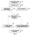
- FIG. 3 is a flowchart describing an exemplary method of operating the system of FIG. 1 .
- a system 1 for providing remote monitoring of a commercial or residential building 2 .
- the system 1 may include a plurality of sensors 4 positioned throughout the building, and a Digital Alarm Communicator Transmitter (DACT) 6 housed within a security system panel 8 .
- the DACT 6 may be in communication with the plurality of sensors 4 to receive signals therefrom.
- the connections between the DACT and some or all of the sensors can be hard wire connections or they may be wireless connections.
- a communication link 10 may be provided between the panel 8 and a receiver 12 located at a central monitoring facility 14 .
- the receiver 12 may have one or more line cards 16 equipped to receive and process signals transmitted from the panel 8 .
- the line cards 16 may also be equipped to send signals to the panel 8 via the communication link 10 .
- the central monitoring facility 14 is geographically remote from the building 1 being monitored, and in practical application the central monitoring facility 14 will monitor signals received from a plurality of different buildings.
- the communication link 10 between the panel 8 and the receiver 12 may be any of a variety of analog or digital communications forms.
- the communications link may be an analog phone line or it may be a digital transmission line.
- a portion or all of the communications link may be a hard wired or wireless connection.
- a non-limiting list of exemplary technologies making up the communication link includes analog or digital phone lines, fiber optic lines, T1 or T2 lines, public/private networks, wireless (Radio Frequency (RF)), cellular and/or satellite connections.
- RF Radio Frequency
- a portion of the communication link 10 may be a public or private network.
- the receiver 12 may include one or more line cards 16 equipped to receive and process the incoming signals from the panel 8 .
- the nature of the signal is not critical to the disclosed system, and any of a variety of input signals may be received and processed by the line card 16 .
- the line card 16 may include a variety of filtering, amplifying and processing (e.g., digital signal processor (DSP)) components.
- DSP digital signal processor
- PSTN public switched telephone network
- the central monitoring facility 14 has a plurality of receivers 12 , each of which is configured to accept a plurality of inputs from panels 8 located in a plurality of different monitored buildings.
- Each line card 16 may be programmed to recognize a variety of different predetermined input signals transmitted from associated panels, and to take certain actions based on those signals.
- the input signals may represent a variety of alarm system “events,” such as the status of the alarm system itself (e.g., that it is operational, that it has been armed, that it has been disarmed), the status of one or more individual alarms or sensors in the monitored building 1 (e.g., that a window or door has been opened or that a smoke or fire detector is experiencing an alarm condition).
- the panel 8 may also send periodic signals to the receiver 12 to “check in,” confirming that the panel is functioning and/or updating the panel's clock to sync with that of the receiver 12 .
- the line card 16 within the receiver 12 detects a ring from a monitored panel 8 and begins recording event signal data in local memory 16 E, 16 G.
- the line card 16 may process the event signal data to determine if the signal complies with a set of predefined parameters (or protocols). This can be done using any of a variety of known methods. For example, most pulse and dual-tone multi frequency (DTMF) formats require that the panel 8 transmit the same data twice. The receiver 12 then matches the twice transmitted data to confirm they are valid. Another technique is referred to as a checksum calculation in which the last digit transmitted by the panel 8 is a mathematical calculation of the previous digits. If the receiver 12 calculates the same digit, then the transmission is acceptable.
- DTMF dual-tone multi frequency
- the line card 16 may produce a return signal to the panel 8 (often referred to as a “kiss-off”) to inform the panel 8 that the signal was received and recognized, and instructing the panel either to cease sending signals or to send a next set of event signals.
- the line card 16 produces a kiss-off signal to the panel 8 signifying a successful transmission (i.e., one that is fully recognized by the line card 16 ), then the event signal data that was recorded in local memory 16 E, 16 G will be overwritten when further event signals are received and recorded by the line card 16 .
- the line card 16 will not recognize the event signal due to some fault in the transmission and/or associated equipment, then the line card 16 will not produce a kiss-off. If no such kiss-off or positive acknowledgement is produced, the line card 16 will flag the recorded data along with any associated debug information, time stamp, caller ID, and/or raw error codes that were produced with the faulty event signal data. The flag will ensure that the event data will not be overwritten in the local memory 16 E, 16 G when further event signals are received and recorded by the line card 16 .
- the line card 16 may also provide an indication (e.g., alert e-mail, audible sound or message, LED indicator) to a system operator to notify the operator that a suspect signal is available for review.
- the alert message may indicate to the operator that a certain line has received a faulty call, and that data exists in the local memory for review.
- the operator may review the call data immediately to perform basic diagnostics (e.g., to determine if the fault is simply due to a customer or user misdialing the telephone,).
- the call data stored in the local memory 16 E, 16 G may also be reviewed periodically by a shift supervisor or other personnel at the central monitoring facility 14 . It will be appreciated that the step of alerting the operator is optional, because the system will automatically record the incoming signals and the user can simply review the logs periodically to diagnose the faulty signals.
- the system 1 may eliminate deficiencies in previous systems attributable to the placement of additional tapping equipment on the affected phone line.
- the recorded data will provide the reviewer with detailed information about the signal upstream and downstream of the digital signal processor (DSP) and other line card components to enable an application level debug of the faulty signal.
- DSP digital signal processor
- the line card 16 may comprise a PSTN line circuit 16 A for accepting an incoming analog call signal from a panel 8 .
- the received analog call signal may be converted to a digital signal via one or more DSPs 16 B, and then routed through processor signal decoding circuitry 16 C, before being passed on to an operator.
- An analog recording circuit 16 D may tap the signal at a location between the PSTN line circuit 16 A and the DSP 16 B.
- the analog recording circuit 16 D may have a local memory 16 E and/or external memory 16 H for storing the analog signal data.
- Raw digital data debug circuitry 16 F may tap the signal at a location between the DSP 16 B and the processor signal decoding circuitry 16 C.
- the debug circuitry 16 F may have a local memory 16 G and/or external memory 16 H for storing digital signal data and/or debug data.
- the debug circuitry 16 F may also capture signal data downstream of the analog recording circuit 16 D.
- a wide variety of data may be recorded for analysis, including the raw analog audio signal, the raw digital conversion of the signal performed by the DSP 16 B, Caller ID, automatic number identification (ANI) and/or dialed number information service (DNIS), date and time of the call, line card profile (i.e., the parameters of the programming of the card), version of the firmware for individual card components (DSP, controller, etc.), as well as a perceived reason for the failure.
- the disclosed arrangement provides the user with a substantial variety of data from which to select when performing a signal fault analysis.
- a microcontroller 18 associated with the line card 16 may be connected to the line card components 16 A-H in a desired manner.
- the microcontroller 18 may be programmed to verify a variety of signal parameters or protocols to accurately determine where the defect in the data is being generated, thus enabling the user to determine why the signal was rejected.
- the microcontroller 18 may be programmed to analyze a variety of parameters or protocols, such as whether the receiver “heard” the signal from the panel (which could represent a call hang up or a weak signal), whether a checksum was wrong, whether the signal was a fax or wrong number, or whether the receiver simply did not “understand” the data (i.e., the receiver expected a particular format due to the handshake but instead received a format that it did not understand). This information can then be used to determine if the fault occurred in any of the system equipment (e.g., faulty panel, faulty transmission line, faulty receiver equipment).
- the microcontroller 18 may perform other checks as well. For example, if the transmitted data is in a DTMF format, the microcontroller may calculate and confirm one or more checksums. The microcontroller may also check to ensure that the frequency shift keying (FSK) resides within the correct frequencies. The microcontroller 18 further may check to ensure that the panel 8 does not continue to duplicate a faulty signal when that signal is unrecognized by the receiver.
- FSK frequency shift keying
- the system 1 may record the audio data (e.g., in .wav or other appropriate format). This recorded audio data may be sent through a test receiver for debugging. This may also be done to ensure that an implemented fix has appropriately addressed, and that future signals are being correctly received.
- the system 1 may also be configured to accept less than perfect signals from one or more panels 8 .
- a characteristic of the receiver 12 may be adjusted to accommodate the less than perfect signals. This may be advantageous in situations in which it is impractical or uneconomical to fix or adjust a remotely-located panel.
- the software controlling the line card 16 may be adjusted slightly to accept the signals generated by the particular panel 8 , thus eliminating the need to fix the panel. This fix may be implemented in any instance in which the receiver “hears” the signal.
- a non-limiting example in which this may be appropriate is where the customer has set the line sensitivity too low, thus making the line card 16 effectively “deaf” to the panel 8 signal. Widening the sensitivity of the receiver 12 may thus allow an otherwise too-weak signal to be received.
- This technique may also enable the operator of the central monitoring facility 14 to create line card software that will accommodate a library of unique, old, or normally unrecognized panels, thus providing a high degree of flexibility to the system 1 .
- a customer may have a panel that is capable of transmitting event data to the receiver 12 , but the format of the event data may not be recognized by the receiver 12 . Typically this would result in the generation of an error, and the non-compatibility would be confirmed using one or more of the aforementioned diagnostic techniques.
- the user can then place the receiver 12 in a “receive all” mode.
- Personnel at the central monitoring facility 14 may then request the panel-user to transmit a variety of predetermined event signals from the panel 8 to the receiver 12 .
- the panel 8 By knowing what particular “event” each of the event signals represents, code can be developed to accommodate that panel, thus resulting in a customized adaptation for that particular customer.
- the panel 8 would simply need to be able to respond to a handshake produced by the receiver 12 to initiate the data transmission. As noted, this may be an advantage where it is undesirable or impractical to fix an existing panel or to require the user to obtain a new panel.
- the line card software may be adjusted to create complex tones to initiate an individual panel's transmission. This could be “new” (beta) software that the specific customer could utilize. In the worst case (i.e., where the receiver hears the signal but does not recognize the signal format) the raw audio file still can be used to dissect the signal to enable communication.
- the line card 16 may have sufficient local memory 16 E, 16 G to store 10-24 signals before being overwritten.
- the local memory 16 E, 16 G comprises nonvolatile random access memory (RAM).
- RAM nonvolatile random access memory
- one or both local memories 16 E, 16 G may be a small on-board hard disk drive.
- the receiver line card 16 may includes a direct output to a computer 20 so that when a ring is detected the line card 16 instructs the computer 20 to begin recording. The remaining steps would be the same as previously noted. This technique may allow the receiver 8 to leverage the much larger memory capacity of the computer's hard drive, as compared to the local memory (i.e., buffer) 16 E, 16 G of the line card 16 .
- the interface to the computer 20 can be via ethernet, audio cable, USB connection, serial port, wireless, or the like.
- the line card 16 may interface with a USB flash drive 22 .
- the audio recording and associated data may be loaded onto the flash drive 22 , allowing the user to directly collect the data via the USB drive for remote diagnostic analysis.
- the line card 16 may direct that all audio and other data for all events received from the panel 8 be stored in external memory 16 H, 20 to preserve a history of all of the daily event traffic.
- a memory index may be created to enable the user to quickly locate faulty call data for review.
- the index may contain time stamp and other appropriate index marker(s) may also be placed in the index. Additional information that can be stored in the index includes Caller-ID, ANI, and DNIS for the call.
- the system 1 may also function to record two-way audio calls that are passed through the receiver 12 .
- a panel 8 will open an audio line with the receiver 12 subsequent to transmission of certain event data. This may enable a person located in the monitored building 2 to speak to a person at the central monitoring facility 14 , for example, to verify an alarm condition received by the receiver 12 .
- a microphone and transmitter may be provided at the building 2 and the central monitoring facility 14 so the parties can engage in verbal communication (e.g., to convey details of a patient emergency, or to record audio of a burglary in the monitored building).
- the receiver 12 receives a call from a monitored panel 8 and decodes the caller ID of the panel 8 .
- the receiver 12 goes off-hook.
- the receiver 12 proceeds to process the event signal, while at step 400 the receiver concurrently begins to record event data.
- the receiver 12 determines whether the event signal has been successfully received (i.e., whether a kiss-off was produced). If the signal was successfully received, then at step 600 the captured recording is flagged to be overwritten during subsequent recording.
- the captured recording is flagged for storage (i.e., so that it will not be overwritten), and an indication is generated which, in one embodiment, is a notification to an operator that a recording is available for review and analysis.
- the captured recording has been analyzed or copied to another storage media for analysis, then at step 800 the recording is flagged to be overwritten during subsequent recording.
- An activity performed automatically is performed in response to executable instruction or device operation without user direct initiation of the activity.
- FIGS. 1-3 are not exclusive, Other systems, processes and menus may be derived in accordance with the principles of the invention to accomplish the same objectives.
- this invention has been described with reference to particular embodiments, it is to be understood that the embodiments and variations shown and described herein are for illustration purposes only. Modifications to the current design may be implemented by those skilled in the art, without departing from the scope of the invention.
- the processes and applications may, in alternative embodiments, be located on one or more (e.g., distributed) processing devices accessing a network linking the elements of FIGS. 1 and 2 .
- any of the functions and steps provided in FIG. 3 may be implemented in hardware, software or a combination of both and may reside on one or more processing devices located at any location of a network linking the elements of FIGS. 1 and 2 or another linked network, including the Internet.
Abstract
Description
Claims (25)
Priority Applications (7)
| Application Number | Priority Date | Filing Date | Title |
|---|---|---|---|
| US12/394,738 US8077027B2 (en) | 2009-02-27 | 2009-02-27 | System and method for analyzing faulty event transmissions |
| PCT/CA2010/000283 WO2010096932A1 (en) | 2009-02-27 | 2010-02-25 | System and method for analyzing faulty event transmissions |
| EP10745783.0A EP2401731B1 (en) | 2009-02-27 | 2010-02-25 | System and method for analyzing faulty event transmissions |
| CA2751064A CA2751064C (en) | 2009-02-27 | 2010-02-25 | System and method for analyzing faulty event transmissions |
| MX2011008750A MX2011008750A (en) | 2009-02-27 | 2010-02-25 | System and method for analyzing faulty event transmissions. |
| ZA2011/05175A ZA201105175B (en) | 2009-02-27 | 2011-07-13 | System and method for analyzing faulty event transmissions |
| CL2011001893A CL2011001893A1 (en) | 2009-02-27 | 2011-08-05 | Method and system for identifying event transmissions that includes the reception of event signal data from a remote panel, the processing of said data, the recording of said data, determining whether they comply with a defined protocol or parameter and identifying the data as data to overwrite or memorize. |
Applications Claiming Priority (1)
| Application Number | Priority Date | Filing Date | Title |
|---|---|---|---|
| US12/394,738 US8077027B2 (en) | 2009-02-27 | 2009-02-27 | System and method for analyzing faulty event transmissions |
Publications (2)
| Publication Number | Publication Date |
|---|---|
| US20100219970A1 US20100219970A1 (en) | 2010-09-02 |
| US8077027B2 true US8077027B2 (en) | 2011-12-13 |
Family
ID=42664980
Family Applications (1)
| Application Number | Title | Priority Date | Filing Date |
|---|---|---|---|
| US12/394,738 Active 2030-03-19 US8077027B2 (en) | 2009-02-27 | 2009-02-27 | System and method for analyzing faulty event transmissions |
Country Status (7)
| Country | Link |
|---|---|
| US (1) | US8077027B2 (en) |
| EP (1) | EP2401731B1 (en) |
| CA (1) | CA2751064C (en) |
| CL (1) | CL2011001893A1 (en) |
| MX (1) | MX2011008750A (en) |
| WO (1) | WO2010096932A1 (en) |
| ZA (1) | ZA201105175B (en) |
Families Citing this family (3)
| Publication number | Priority date | Publication date | Assignee | Title |
|---|---|---|---|---|
| CA2750066C (en) | 2009-01-23 | 2020-05-26 | Tyco Safety Products Canada Ltd. | Facsimile aware alarm monitoring station and method |
| US9015529B2 (en) * | 2012-03-13 | 2015-04-21 | Harman International Industries, Incorporated | System for remote installed sound compliance testing |
| EP3404928B1 (en) * | 2017-05-19 | 2020-11-25 | Safco Engineering S.p.A. | Improved electronic unit for controlling fire sensors |
Citations (6)
| Publication number | Priority date | Publication date | Assignee | Title |
|---|---|---|---|---|
| US6124806A (en) * | 1997-09-12 | 2000-09-26 | Williams Wireless, Inc. | Wide area remote telemetry |
| WO2001052478A2 (en) | 2000-01-07 | 2001-07-19 | Invensys Controls Plc | Building control |
| US6658091B1 (en) | 2002-02-01 | 2003-12-02 | @Security Broadband Corp. | LIfestyle multimedia security system |
| US6968294B2 (en) * | 2001-03-15 | 2005-11-22 | Koninklijke Philips Electronics N.V. | Automatic system for monitoring person requiring care and his/her caretaker |
| US7057507B1 (en) * | 2003-04-14 | 2006-06-06 | Sandifer Robert L | Flood detection and alarm system |
| US7131136B2 (en) * | 2002-07-10 | 2006-10-31 | E-Watch, Inc. | Comprehensive multi-media surveillance and response system for aircraft, operations centers, airports and other commercial transports, centers and terminals |
Family Cites Families (4)
| Publication number | Priority date | Publication date | Assignee | Title |
|---|---|---|---|---|
| CA2286663A1 (en) * | 1997-04-10 | 1998-10-15 | Nexsys Commtech International Inc. | Remote home monitoring system |
| US6914893B2 (en) * | 1998-06-22 | 2005-07-05 | Statsignal Ipc, Llc | System and method for monitoring and controlling remote devices |
| WO2001091438A1 (en) | 2000-05-19 | 2001-11-29 | Synapse Wireless, Inc. | Method and apparatus for generating dynamic graphical representations and real-time notification of the status of a remotely monitored system |
| US7472332B2 (en) * | 2005-07-26 | 2008-12-30 | International Business Machines Corporation | Method for the reliability of host data stored on fibre channel attached storage subsystems |
-
2009
- 2009-02-27 US US12/394,738 patent/US8077027B2/en active Active
-
2010
- 2010-02-25 EP EP10745783.0A patent/EP2401731B1/en active Active
- 2010-02-25 WO PCT/CA2010/000283 patent/WO2010096932A1/en active Application Filing
- 2010-02-25 MX MX2011008750A patent/MX2011008750A/en active IP Right Grant
- 2010-02-25 CA CA2751064A patent/CA2751064C/en active Active
-
2011
- 2011-07-13 ZA ZA2011/05175A patent/ZA201105175B/en unknown
- 2011-08-05 CL CL2011001893A patent/CL2011001893A1/en unknown
Patent Citations (7)
| Publication number | Priority date | Publication date | Assignee | Title |
|---|---|---|---|---|
| US6124806A (en) * | 1997-09-12 | 2000-09-26 | Williams Wireless, Inc. | Wide area remote telemetry |
| WO2001052478A2 (en) | 2000-01-07 | 2001-07-19 | Invensys Controls Plc | Building control |
| US6968294B2 (en) * | 2001-03-15 | 2005-11-22 | Koninklijke Philips Electronics N.V. | Automatic system for monitoring person requiring care and his/her caretaker |
| US6658091B1 (en) | 2002-02-01 | 2003-12-02 | @Security Broadband Corp. | LIfestyle multimedia security system |
| US7120233B2 (en) * | 2002-02-01 | 2006-10-10 | @Security Broadband Corp. | Lifestyle multimedia security system |
| US7131136B2 (en) * | 2002-07-10 | 2006-10-31 | E-Watch, Inc. | Comprehensive multi-media surveillance and response system for aircraft, operations centers, airports and other commercial transports, centers and terminals |
| US7057507B1 (en) * | 2003-04-14 | 2006-06-06 | Sandifer Robert L | Flood detection and alarm system |
Also Published As
| Publication number | Publication date |
|---|---|
| MX2011008750A (en) | 2011-09-06 |
| EP2401731B1 (en) | 2019-09-11 |
| EP2401731A1 (en) | 2012-01-04 |
| ZA201105175B (en) | 2012-09-26 |
| CA2751064A1 (en) | 2010-09-02 |
| EP2401731A4 (en) | 2014-02-26 |
| WO2010096932A1 (en) | 2010-09-02 |
| CA2751064C (en) | 2015-09-22 |
| US20100219970A1 (en) | 2010-09-02 |
| CL2011001893A1 (en) | 2011-10-14 |
Similar Documents
| Publication | Publication Date | Title |
|---|---|---|
| US5511109A (en) | Security system using call display | |
| CA2751064C (en) | System and method for analyzing faulty event transmissions | |
| KR100969661B1 (en) | System for reporting fire promptly and monitoring fire report automatically and method for operating thereof | |
| KR102069539B1 (en) | Emergency call system with audio check function | |
| JP2009159003A (en) | Intercom system for multiple dwelling | |
| KR102402487B1 (en) | An Alarm System Capable of Checking Normal Operation | |
| JP4789528B2 (en) | Fire alarm system for apartment houses | |
| EP2389667B1 (en) | Facsimile aware alarm monitoring station and method | |
| JP2007114915A (en) | Automatic maintenance checking system based on transmission of information from reporting device installed on user side utilizing self-diagnostic checking system | |
| JP2002083390A (en) | Fire alarm system and its inspection method | |
| AU2013219172B2 (en) | Method and system for enhancing alarm security | |
| US10665086B1 (en) | Cognitive virtual central monitoring station and methods therefor | |
| KR100817534B1 (en) | Auto fire streamline, wireless prompt report system and prompt report method thereof | |
| JP2835835B2 (en) | Monitoring system and monitoring method | |
| KR100980371B1 (en) | System and method for data interlocking system between standard emergency rescue system and fire detection receiver | |
| JP2017117142A (en) | Security device and security business support system | |
| US7646853B2 (en) | Security system reporting which compares a caller telephone number with a ten digit account number | |
| JP2000307748A (en) | Telephone set for welfare management | |
| JP3310792B2 (en) | Automatic notification method and automatic notification device | |
| CN115981952A (en) | Service monitoring alarm method and device | |
| JP4075940B2 (en) | Apartment fire alarm system, residential building receiver | |
| KR20230065800A (en) | Fire monitoring methods and systems | |
| JPS6224400A (en) | Building remote monitor | |
| JP2009267567A (en) | Intercom system | |
| KR20040098993A (en) | System of wireless paging for Auto diagnosis Telemeter using at the bank, and so on and method for Auto diagnosis Telemeter thereof |
Legal Events
| Date | Code | Title | Description |
|---|---|---|---|
| AS | Assignment |
Owner name: TYCO SAFETY PRODUCTS CANADA LTD., CANADA Free format text: ASSIGNMENT OF ASSIGNORS INTEREST;ASSIGNOR:FOISY, STEPHANE;REEL/FRAME:022324/0728 Effective date: 20090224 |
|
| STCF | Information on status: patent grant |
Free format text: PATENTED CASE |
|
| FPAY | Fee payment |
Year of fee payment: 4 |
|
| MAFP | Maintenance fee payment |
Free format text: PAYMENT OF MAINTENANCE FEE, 8TH YEAR, LARGE ENTITY (ORIGINAL EVENT CODE: M1552); ENTITY STATUS OF PATENT OWNER: LARGE ENTITY Year of fee payment: 8 |
|
| AS | Assignment |
Owner name: JOHNSON CONTROLS TYCO IP HOLDINGS LLP, WISCONSIN Free format text: ASSIGNMENT OF ASSIGNORS INTEREST;ASSIGNOR:TYCO SAFETY PRODUCTS CANADA LTD;REEL/FRAME:058562/0714 Effective date: 20210617 |
|
| AS | Assignment |
Owner name: JOHNSON CONTROLS TYCO IP HOLDINGS LLP, WISCONSIN Free format text: NUNC PRO TUNC ASSIGNMENT;ASSIGNOR:TYCO SAFETY PRODUCTS CANADA LTD.;REEL/FRAME:058957/0105 Effective date: 20210806 |
|
| MAFP | Maintenance fee payment |
Free format text: PAYMENT OF MAINTENANCE FEE, 12TH YEAR, LARGE ENTITY (ORIGINAL EVENT CODE: M1553); ENTITY STATUS OF PATENT OWNER: LARGE ENTITY Year of fee payment: 12 |