US8075517B2 - Medicament delivery device - Google Patents
Medicament delivery device Download PDFInfo
- Publication number
- US8075517B2 US8075517B2 US12/996,232 US99623209A US8075517B2 US 8075517 B2 US8075517 B2 US 8075517B2 US 99623209 A US99623209 A US 99623209A US 8075517 B2 US8075517 B2 US 8075517B2
- Authority
- US
- United States
- Prior art keywords
- plunger rod
- flexible locking
- locking device
- container
- distal
- Prior art date
- Legal status (The legal status is an assumption and is not a legal conclusion. Google has not performed a legal analysis and makes no representation as to the accuracy of the status listed.)
- Active
Links
Images


Classifications
-
- A—HUMAN NECESSITIES
- A61—MEDICAL OR VETERINARY SCIENCE; HYGIENE
- A61M—DEVICES FOR INTRODUCING MEDIA INTO, OR ONTO, THE BODY; DEVICES FOR TRANSDUCING BODY MEDIA OR FOR TAKING MEDIA FROM THE BODY; DEVICES FOR PRODUCING OR ENDING SLEEP OR STUPOR
- A61M5/00—Devices for bringing media into the body in a subcutaneous, intra-vascular or intramuscular way; Accessories therefor, e.g. filling or cleaning devices, arm-rests
- A61M5/178—Syringes
- A61M5/20—Automatic syringes, e.g. with automatically actuated piston rod, with automatic needle injection, filling automatically
-
- A—HUMAN NECESSITIES
- A61—MEDICAL OR VETERINARY SCIENCE; HYGIENE
- A61M—DEVICES FOR INTRODUCING MEDIA INTO, OR ONTO, THE BODY; DEVICES FOR TRANSDUCING BODY MEDIA OR FOR TAKING MEDIA FROM THE BODY; DEVICES FOR PRODUCING OR ENDING SLEEP OR STUPOR
- A61M5/00—Devices for bringing media into the body in a subcutaneous, intra-vascular or intramuscular way; Accessories therefor, e.g. filling or cleaning devices, arm-rests
- A61M5/178—Syringes
- A61M5/24—Ampoule syringes, i.e. syringes with needle for use in combination with replaceable ampoules or carpules, e.g. automatic
- A61M5/2448—Ampoule syringes, i.e. syringes with needle for use in combination with replaceable ampoules or carpules, e.g. automatic comprising means for injection of two or more media, e.g. by mixing
-
- A—HUMAN NECESSITIES
- A61—MEDICAL OR VETERINARY SCIENCE; HYGIENE
- A61M—DEVICES FOR INTRODUCING MEDIA INTO, OR ONTO, THE BODY; DEVICES FOR TRANSDUCING BODY MEDIA OR FOR TAKING MEDIA FROM THE BODY; DEVICES FOR PRODUCING OR ENDING SLEEP OR STUPOR
- A61M5/00—Devices for bringing media into the body in a subcutaneous, intra-vascular or intramuscular way; Accessories therefor, e.g. filling or cleaning devices, arm-rests
- A61M5/178—Syringes
- A61M5/31—Details
- A61M5/315—Pistons; Piston-rods; Guiding, blocking or restricting the movement of the rod or piston; Appliances on the rod for facilitating dosing ; Dosing mechanisms
- A61M5/31511—Piston or piston-rod constructions, e.g. connection of piston with piston-rod
-
- A—HUMAN NECESSITIES
- A61—MEDICAL OR VETERINARY SCIENCE; HYGIENE
- A61M—DEVICES FOR INTRODUCING MEDIA INTO, OR ONTO, THE BODY; DEVICES FOR TRANSDUCING BODY MEDIA OR FOR TAKING MEDIA FROM THE BODY; DEVICES FOR PRODUCING OR ENDING SLEEP OR STUPOR
- A61M5/00—Devices for bringing media into the body in a subcutaneous, intra-vascular or intramuscular way; Accessories therefor, e.g. filling or cleaning devices, arm-rests
- A61M5/42—Devices for bringing media into the body in a subcutaneous, intra-vascular or intramuscular way; Accessories therefor, e.g. filling or cleaning devices, arm-rests having means for desensitising skin, for protruding skin to facilitate piercing, or for locating point where body is to be pierced
- A61M5/422—Desensitising skin
-
- A—HUMAN NECESSITIES
- A61—MEDICAL OR VETERINARY SCIENCE; HYGIENE
- A61M—DEVICES FOR INTRODUCING MEDIA INTO, OR ONTO, THE BODY; DEVICES FOR TRANSDUCING BODY MEDIA OR FOR TAKING MEDIA FROM THE BODY; DEVICES FOR PRODUCING OR ENDING SLEEP OR STUPOR
- A61M5/00—Devices for bringing media into the body in a subcutaneous, intra-vascular or intramuscular way; Accessories therefor, e.g. filling or cleaning devices, arm-rests
- A61M5/178—Syringes
- A61M5/24—Ampoule syringes, i.e. syringes with needle for use in combination with replaceable ampoules or carpules, e.g. automatic
- A61M2005/2403—Ampoule inserted into the ampoule holder
- A61M2005/2407—Ampoule inserted into the ampoule holder from the rear
-
- A—HUMAN NECESSITIES
- A61—MEDICAL OR VETERINARY SCIENCE; HYGIENE
- A61M—DEVICES FOR INTRODUCING MEDIA INTO, OR ONTO, THE BODY; DEVICES FOR TRANSDUCING BODY MEDIA OR FOR TAKING MEDIA FROM THE BODY; DEVICES FOR PRODUCING OR ENDING SLEEP OR STUPOR
- A61M5/00—Devices for bringing media into the body in a subcutaneous, intra-vascular or intramuscular way; Accessories therefor, e.g. filling or cleaning devices, arm-rests
- A61M5/178—Syringes
- A61M5/24—Ampoule syringes, i.e. syringes with needle for use in combination with replaceable ampoules or carpules, e.g. automatic
- A61M5/2448—Ampoule syringes, i.e. syringes with needle for use in combination with replaceable ampoules or carpules, e.g. automatic comprising means for injection of two or more media, e.g. by mixing
- A61M2005/2451—Ampoule syringes, i.e. syringes with needle for use in combination with replaceable ampoules or carpules, e.g. automatic comprising means for injection of two or more media, e.g. by mixing preventing delivery before mixing is completed, e.g. by locking mechanisms
-
- A—HUMAN NECESSITIES
- A61—MEDICAL OR VETERINARY SCIENCE; HYGIENE
- A61M—DEVICES FOR INTRODUCING MEDIA INTO, OR ONTO, THE BODY; DEVICES FOR TRANSDUCING BODY MEDIA OR FOR TAKING MEDIA FROM THE BODY; DEVICES FOR PRODUCING OR ENDING SLEEP OR STUPOR
- A61M5/00—Devices for bringing media into the body in a subcutaneous, intra-vascular or intramuscular way; Accessories therefor, e.g. filling or cleaning devices, arm-rests
- A61M5/178—Syringes
- A61M5/24—Ampoule syringes, i.e. syringes with needle for use in combination with replaceable ampoules or carpules, e.g. automatic
- A61M2005/2485—Ampoule holder connected to rest of syringe
- A61M2005/2488—Ampoule holder connected to rest of syringe via rotation, e.g. threads or bayonet
-
- A—HUMAN NECESSITIES
- A61—MEDICAL OR VETERINARY SCIENCE; HYGIENE
- A61M—DEVICES FOR INTRODUCING MEDIA INTO, OR ONTO, THE BODY; DEVICES FOR TRANSDUCING BODY MEDIA OR FOR TAKING MEDIA FROM THE BODY; DEVICES FOR PRODUCING OR ENDING SLEEP OR STUPOR
- A61M2205/00—General characteristics of the apparatus
- A61M2205/58—Means for facilitating use, e.g. by people with impaired vision
- A61M2205/581—Means for facilitating use, e.g. by people with impaired vision by audible feedback
-
- A—HUMAN NECESSITIES
- A61—MEDICAL OR VETERINARY SCIENCE; HYGIENE
- A61M—DEVICES FOR INTRODUCING MEDIA INTO, OR ONTO, THE BODY; DEVICES FOR TRANSDUCING BODY MEDIA OR FOR TAKING MEDIA FROM THE BODY; DEVICES FOR PRODUCING OR ENDING SLEEP OR STUPOR
- A61M5/00—Devices for bringing media into the body in a subcutaneous, intra-vascular or intramuscular way; Accessories therefor, e.g. filling or cleaning devices, arm-rests
- A61M5/178—Syringes
- A61M5/20—Automatic syringes, e.g. with automatically actuated piston rod, with automatic needle injection, filling automatically
- A61M5/2033—Spring-loaded one-shot injectors with or without automatic needle insertion
-
- A—HUMAN NECESSITIES
- A61—MEDICAL OR VETERINARY SCIENCE; HYGIENE
- A61M—DEVICES FOR INTRODUCING MEDIA INTO, OR ONTO, THE BODY; DEVICES FOR TRANSDUCING BODY MEDIA OR FOR TAKING MEDIA FROM THE BODY; DEVICES FOR PRODUCING OR ENDING SLEEP OR STUPOR
- A61M5/00—Devices for bringing media into the body in a subcutaneous, intra-vascular or intramuscular way; Accessories therefor, e.g. filling or cleaning devices, arm-rests
- A61M5/178—Syringes
- A61M5/24—Ampoule syringes, i.e. syringes with needle for use in combination with replaceable ampoules or carpules, e.g. automatic
-
- A—HUMAN NECESSITIES
- A61—MEDICAL OR VETERINARY SCIENCE; HYGIENE
- A61M—DEVICES FOR INTRODUCING MEDIA INTO, OR ONTO, THE BODY; DEVICES FOR TRANSDUCING BODY MEDIA OR FOR TAKING MEDIA FROM THE BODY; DEVICES FOR PRODUCING OR ENDING SLEEP OR STUPOR
- A61M5/00—Devices for bringing media into the body in a subcutaneous, intra-vascular or intramuscular way; Accessories therefor, e.g. filling or cleaning devices, arm-rests
- A61M5/178—Syringes
- A61M5/31—Details
- A61M5/3129—Syringe barrels
Definitions
- the present invention relates to a medicament delivery device and in particular an injector for injecting medicament into the body of a patient.
- Medicament delivery devices such as injectors have become widespread on the market, and in particular injectors primarily intended for self-administration of medicament.
- injectors should be easy and almost intuitive to handle and use, and therefore a number of automatic or semi-automatic features are built in.
- an injection device comprising an auto injection mechanism comprising a plunger rod operated by an injection spring for expelling a preset dose of medicament and a user controlled releasable plunger rod locking mechanism.
- the latter comprises a longitudinal groove with a wedge-shaped cross-section and a locking lug with cooperating cross-section.
- the locking lug is urged into the groove for locking the movement of the plunger rod.
- the locking lug can be moved out of contact with the groove by a user-operated handle whereby the plunger rod is moved, until the handle is again released or that the plunger rod comes to a dose stop.
- the user is capable of controlling the injection sequence via the handle/lug in and out of frictional contact with the groove of the plunger rod.
- a drawback with the device according to '111 is the use of frictional forces for holding/locking said plunger rod.
- a person skilled in the art is well aware of that the force from an injection spring needs to be rather high, in particular at the start of the injection sequence for overcoming the initial forces for moving a stopper inside the medicament container. It is thus not certain that the friction forces are capable of withstanding the forces from the injection spring.
- the aim of the present invention is to remedy the drawbacks with the state of the art devices and to allow a dose of medicament to be delivered in sequence in smaller parts with temporary stops of the delivery.
- a medicament delivery device comprising a generally tubular distal housing part; a generally tubular medicament container holder having opposite distal and proximal ends, wherein its distal end is releasably connected to said distal housing part and wherein its proximal end is releasably connected to a delivery member; a medicament container having at least one slidable stopper, wherein the container is arranged within the container holder; a plunger rod having opposite proximal and distal ends and being arranged within said distal housing part, wherein the proximal end of the plunger rod is abutting the at least one stopper; resilient force means operably connected to said plunger rod for driving said plunger rod and thereby said at least one stopper towards the proximal end of the device, an actuation means comprising flexible locking means releasably connected to said plunger rod for holding said plunger rod and thereby said resilient force means in a pre-tensioned state,
- said flexible locking means are flexible tongues
- said stop engagement means of the flexible locking means are inwardly directed protrusions
- said stop engagement means of the plunger rod are circumferential grooves.
- said medicament container is a multi chamber container comprising at least two substances.
- the distal housing part comprises mix engagement means arranged to cooperate with corresponding mix engagement means arranged on the distal end of the container holder, such that a distal displacement of the container holder in relation to the distal housing part causes a distal displacement of the container in relation to the plunger rod, whereby the plunger rod forces the stopper to be proximally displaced and thereby a mixing of the substances within the container is performed.
- said mix engagement means are threads.
- the stop engagement means of the flexible locking means the stop engagement means of the plunger rod are circumferential produces audible indications as long as a continuous delivery is in progress.
- the present invention has a number of advantages.
- the main advantage is that the manually operated actuation means is capable of releasing, but also locking, the plunger rod even after release. This means that the plunger rod can be locked in different positions during its travel, and thus during expelling of medicament.
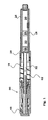
- FIG. 1 is a cross-sectional view of one embodiment of the present invention
- FIG. 2 is detailed view of a part of the embodiment of FIG. 1 .
- FIG. 3 is a further detailed view corresponding to FIG. 2 .
- distal part/end refers to the part/end of the medicament delivery device, or the parts/ends of the members thereof, which under use of the medicament delivery device is located the furthest away from the medicament delivery site of the patient.
- proximal part/end refers to the part/end of the medicament delivery device, or the parts/ends of the members thereof, which under use of the device is located closest to the medicament delivery site of the patient.
- a medicament delivery device shown in the figures comprises a generally tubular distal housing part 19 ; a generally tubular medicament container holder 16 having opposite distal and proximal ends, wherein its distal end is releasably connected to said distal housing part and wherein its proximal end is releasably connected to a delivery member; a medicament container 18 having at least one slidable stopper, wherein the container is arranged within the container holder; a plunger rod 32 having opposite proximal and distal ends and being arranged within said distal housing part, wherein the proximal end of the plunger rod is abutting the at least one stopper; resilient force means operably connected to said plunger rod for driving said plunger rod and thereby said at least one stopper towards the proximal end of the device, an actuation means 34 comprising flexible locking means 36 releasably connected to said plunger rod for holding said plunger rod and thereby said resilient force means in a pre-tensioned state, and
- the medicament container 18 is a so called multiple chamber container where one chamber 20 contains medicament in powder form and the other chamber 22 contains a diluent.
- the two chambers are sealed off by a first stopper 24 .
- the end of the container is sealed off by a second stopper 26 .
- the outer surface of the medicament container holder 16 is arranged with mix engagement means 28 as e.g. threads.
- the plunger rod 32 is partially surrounded by the actuation means 34 .
- the proximal end of the actuation sleeve 34 is arranged with the flexible locking means 36 which are flexible tongues.
- Each tongue is arranged with the stop engagement means 37 which are inwardly directed protrusions.
- these stop engagement means 37 are positioned in corresponding stop engagement means 38 which is a first circumferential groove on the plunger rod where the groove acts as a stop ledge on which the protrusions 37 rest.
- a number of circumferential grooves are arranged, the function of which will be described below.
- the tongues 36 and protrusions 37 are held in this initial position by the release means 40 .
- the resilient force means which is e.g. a spring (not shown) is arranged compressed between a proximal wall part of the plunger rod and a distal wall part of the actuation means 34 .
- the distal end of the actuation means 34 which is the activation button 48 protrudes distally though the distal end of the distal housing part.
- the actuation means is further arranged with a ledge 50 preventing the actuation means from moving in the distal direction.
- the inner surface of the distal housing part 29 is further arranged with mix engagement means 52 as e.g. threads having a corresponding pitch as the threads 28 of the container holder 16 .
- the distal end of the resilient means 60 rests against the ledge 50 of the actuation means 34 and the proximal end of the resilient means rests against a ledge of the release means 40 .
- the medicament container When the device is delivered to a user/patient, the medicament container is already placed within the medicament holder, the medicament holder is attached to the distal housing part, and the proximal end of the plunger rod is abutting the stopper arranged within the medicament container.
- the container holder 16 When the medicament container is a single chamber medicament container; the container holder 16 is somewhat distally displaced into the distal housing such that the distal end of the container holder comes in contact with the proximal end of the release means 40 and forces distally said release means compressing said resilient means 60 , such that it is only partly in contact with the flexible tongues of the actuation means.
- the container holder is distally displaced e.g. threaded into the distal housing part. Because the plunger rod is stationary and is abutting the second stopper 26 , the second stopper 26 is forced against the plunger rod. Due to the incompressibility of the diluent in the chamber, the first stopper 24 is also moved, whereby passages of the container are freed between the first and the second chamber 20 , 22 and a mixing is obtained. The user can now stop the distally displacement of the container holder. This may be indicated in a window 58 arranged on a surface on the proximal end of the distal housing part. A delivery member as e.g. a pen needle (not shown) is then attached to the proximal end of the container holder whereby a priming of the device is performed.
- a delivery member as e.g. a pen needle (not shown) is then attached to the proximal end of the container holder whereby a priming of the device is performed.
- the device now is positioned at the intended delivery site e.g. an injection site, the delivery member which is e.g. a pen needle penetrates the skin, and the medicament is injected by proximally depressing the actuation button 48 .
- This causes the actuation means 34 to move proximally, whereby the flexible tongues 36 flexes radially outwards causing the protrusions 37 to be moved out of the annular groove 38 , which releases the plunger rod 32 .
- the accumulated force in the pre-tensioned resilient force means forces the plunger rod to push the stoppers 24 , 26 in the proximal direction whereby the expelling of a dose of medicament through the delivery member is initiated.
- the patient/user feels pain or discomfort he/she can release the pressure on the actuation button 48 .
- This causes the actuation means 34 to move distally due to the compression force of the resilient means, whereby the flexible tongues 36 are forced inwards toward the plunger rod due to the contact with the release means 40 .
- the protrusions 37 of the tongues 36 will be positioned in one of the grooves 38 , whereby the movement of the plunger rod 32 is stopped.
- the patient can now rest a while and let the delivered medicament to spread in the tissue.
- he/she merely presses the actuation button 48 as described above and the delivery continues.
- This sequence with temporary stops may be performed a number of times until the last annular groove 38 has passed the protrusions 37 .
- the patient does not have to stop but could let the device perform a continuous injection until the stoppers are in the foremost proximal position inside the medicament container.
- the protrusions 37 of the flexible tongues 36 will merely slide over the annular grooves 38 , whereby an audible indication is obtained as long as a continuous delivery is performed.
- this indication stops this in turn is an indication that the delivery is completed.
- the device After the delivery is completed and the delivery member has been withdrawn, the device is discarded. Further, additional features such as automatic penetration function, automatic needle shield function and the like can be used.
Abstract
Description
Claims (11)
Applications Claiming Priority (3)
| Application Number | Priority Date | Filing Date | Title |
|---|---|---|---|
| SE0801367 | 2008-06-11 | ||
| SE0801367 | 2008-06-11 | ||
| PCT/EP2009/056672 WO2009150071A1 (en) | 2008-06-11 | 2009-05-29 | Medicament delivery device |
Publications (2)
| Publication Number | Publication Date |
|---|---|
| US20110077589A1 US20110077589A1 (en) | 2011-03-31 |
| US8075517B2 true US8075517B2 (en) | 2011-12-13 |
Family
ID=41091990
Family Applications (1)
| Application Number | Title | Priority Date | Filing Date |
|---|---|---|---|
| US12/996,232 Active US8075517B2 (en) | 2008-06-11 | 2009-05-29 | Medicament delivery device |
Country Status (6)
| Country | Link |
|---|---|
| US (1) | US8075517B2 (en) |
| EP (1) | EP2296732B1 (en) |
| CN (1) | CN102112165B (en) |
| AU (1) | AU2009256710B2 (en) |
| DK (1) | DK2296732T3 (en) |
| WO (1) | WO2009150071A1 (en) |
Cited By (10)
| Publication number | Priority date | Publication date | Assignee | Title |
|---|---|---|---|---|
| US20100137791A1 (en) * | 2008-12-02 | 2010-06-03 | Sanofi-Aventis Deutschland Gmbh | Drive assembly suitable for use in a medication delivery device an medication delivery device |
| US20110213315A1 (en) * | 2008-09-18 | 2011-09-01 | Becton, Dickinson And Company | Medical injector with slidable sleeve activation |
| US20120172814A1 (en) * | 2009-06-01 | 2012-07-05 | Sanofi-Aventis Deutschland Gmbh | Resetting mechanism for a drug delivery device |
| US9751056B2 (en) | 2012-01-23 | 2017-09-05 | Merit Medical Systems, Inc. | Mixing syringe |
| US10220048B2 (en) | 2013-03-15 | 2019-03-05 | Aerpio Therapeutics, Inc. | Compositions and methods for treating ocular diseases |
| US10376644B2 (en) | 2013-04-05 | 2019-08-13 | Novo Nordisk A/S | Dose logging device for a drug delivery device |
| EP3607821A1 (en) | 2013-03-15 | 2020-02-12 | Aerpio Therapeutics, Inc. | Compositions, formulations and methods for treating ocular diseases |
| US11065386B2 (en) | 2014-12-03 | 2021-07-20 | Eli Lilly And Company | Automatic medication injection device with audible indication of injecting progress |
| US11617753B2 (en) | 2016-11-10 | 2023-04-04 | Oyagen, Inc. | Methods of treating and inhibiting Ebola virus infection |
| US11738025B2 (en) | 2020-02-04 | 2023-08-29 | Oyagen, Inc. | Method for treating coronavirus infections |
Families Citing this family (19)
| Publication number | Priority date | Publication date | Assignee | Title |
|---|---|---|---|---|
| US7648483B2 (en) | 2004-11-22 | 2010-01-19 | Intelliject, Inc. | Devices, systems and methods for medicament delivery |
| US11590286B2 (en) | 2004-11-22 | 2023-02-28 | Kaleo, Inc. | Devices, systems and methods for medicament delivery |
| US10737028B2 (en) | 2004-11-22 | 2020-08-11 | Kaleo, Inc. | Devices, systems and methods for medicament delivery |
| JP4960252B2 (en) | 2004-11-22 | 2012-06-27 | インテリジェクト,インコーポレイテッド | Device, system and method for drug delivery |
| US7947017B2 (en) | 2004-11-22 | 2011-05-24 | Intelliject, Inc. | Devices, systems and methods for medicament delivery |
| US9022980B2 (en) | 2005-02-01 | 2015-05-05 | Kaleo, Inc. | Medical injector simulation device |
| US8231573B2 (en) | 2005-02-01 | 2012-07-31 | Intelliject, Inc. | Medicament delivery device having an electronic circuit system |
| ES2396745T3 (en) | 2005-02-01 | 2013-02-25 | Intelliject, Inc. | Devices for medication administration |
| USD994111S1 (en) | 2008-05-12 | 2023-08-01 | Kaleo, Inc. | Medicament delivery device cover |
| AU2011214922B2 (en) * | 2010-02-09 | 2012-12-13 | Shl Medical Ag | Medicament delivery device |
| US9084849B2 (en) | 2011-01-26 | 2015-07-21 | Kaleo, Inc. | Medicament delivery devices for administration of a medicament within a prefilled syringe |
| US8939943B2 (en) | 2011-01-26 | 2015-01-27 | Kaleo, Inc. | Medicament delivery device for administration of opioid antagonists including formulations for naloxone |
| US8627816B2 (en) | 2011-02-28 | 2014-01-14 | Intelliject, Inc. | Medicament delivery device for administration of opioid antagonists including formulations for naloxone |
| JP5732549B2 (en) * | 2011-02-03 | 2015-06-10 | エス・ホー・エル・グループ・アクチボラゲットShl Group Ab | Drug delivery device |
| HUE042577T2 (en) * | 2015-01-28 | 2019-07-29 | Cube Pharmaceuticals N Kalofolias&Co Oe | Devices and methods for establishing communication between chambers in a multi-chambered vessel |
| JP7014797B2 (en) | 2016-12-23 | 2022-02-01 | カレオ,インコーポレイテッド | Drug delivery devices and methods for delivering drugs to babies and children |
| EP3737442A1 (en) * | 2018-01-09 | 2020-11-18 | SHL Medical AG | Support structure |
| GB2577696B (en) * | 2018-10-01 | 2022-09-14 | Janssen Pharmaceuticals Inc | Latch for an injection device and an injection device trainer |
| GB2604584B (en) * | 2021-02-28 | 2023-08-02 | Owen Mumford Ltd | Injector apparatus facilitating automatic needle withdrawal |
Citations (35)
| Publication number | Priority date | Publication date | Assignee | Title |
|---|---|---|---|---|
| US4394863A (en) * | 1981-10-23 | 1983-07-26 | Survival Technology, Inc. | Automatic injector with cartridge having separate sequentially injectable medicaments |
| US5042977A (en) * | 1987-05-08 | 1991-08-27 | Wilhelm Haselmeier Gmbh & Co. | Injection device which can be cocked only in the zero position |
| US5300030A (en) * | 1991-05-30 | 1994-04-05 | Owen Mumford Limited | Injection devices |
| US5620421A (en) * | 1993-12-09 | 1997-04-15 | Schmitz; William L. | Syringe injector system |
| US20010039394A1 (en) * | 1993-07-31 | 2001-11-08 | Duncan A. Greenhalgh | Needle-less injector |
| US6371939B2 (en) * | 1998-10-26 | 2002-04-16 | Pharmacia Ab | Autoinjector |
| US20020120235A1 (en) * | 2001-01-05 | 2002-08-29 | Christian Enggaard | Automatic injection device with reset feature |
| US20020188251A1 (en) * | 2001-06-08 | 2002-12-12 | Bioject, Inc. | Jet injector apparatus and method |
| US20040127858A1 (en) * | 2002-10-01 | 2004-07-01 | Becton, Dickinson And Company | Medication delivery pen |
| US6953445B2 (en) * | 2000-10-10 | 2005-10-11 | Meridian Medical Technologies, Inc. | Wet/dry automatic injector assembly |
| US20050277886A1 (en) * | 2002-11-25 | 2005-12-15 | Edgar Hommann | Device for automatically injecting an active agent |
| US20060178630A1 (en) * | 2005-01-31 | 2006-08-10 | Anders Bostrom | Device for delivering medicament |
| US7118553B2 (en) * | 2002-11-25 | 2006-10-10 | Tecpharma Licensing Ag | Auto-injector comprising a resettable releasing safety device |
| US20060270985A1 (en) * | 2003-11-05 | 2006-11-30 | Edgar Hommann | Device for administering an injectable product |
| US7291132B2 (en) * | 2003-08-12 | 2007-11-06 | Eli Lilly And Company | Medication dispensing apparatus with triple screw threads for mechanical advantage |
| US7297136B2 (en) * | 2004-12-06 | 2007-11-20 | Wyrick Ronald E | Medicine injection devices and methods |
| US7329239B2 (en) * | 1997-02-05 | 2008-02-12 | Medtronic Minimed, Inc. | Insertion device for an insertion set and method of using the same |
| US7381201B2 (en) * | 2002-06-24 | 2008-06-03 | Alza Corporation | Reusable, spring driven autoinjector |
| US20080147006A1 (en) * | 2006-12-13 | 2008-06-19 | Shl Medical Ab | Auto-Injector |
| US20080154200A1 (en) * | 2005-01-24 | 2008-06-26 | Lesch Paul R | Prefilled syringe jet injector |
| US7500963B2 (en) * | 2003-07-22 | 2009-03-10 | Safety Syringes, Inc. | Systems and methods for automatic medical injection with safeguard |
| US20090137948A1 (en) * | 2007-11-26 | 2009-05-28 | Bioject Inc. | Needle-free injection device with auto-disable |
| US20090137949A1 (en) * | 2007-11-26 | 2009-05-28 | Bioject Inc. | Needle-free injection device with nozzle auto-disable |
| US20090227955A1 (en) * | 2006-08-14 | 2009-09-10 | Juerg Hirschel | Injection device comprising a mechanical lock |
| US20090259181A1 (en) * | 2006-04-12 | 2009-10-15 | Ulrich Moser | Injection device with tensioning spring and tensioning element |
| US20090318865A1 (en) * | 2006-09-29 | 2009-12-24 | Novo Nordisk A/S | Injection Device with Electronic Detecting Means |
| US7674246B2 (en) * | 2004-12-09 | 2010-03-09 | West Pharmaceutical Services Of Delaware, Inc. | Automatic injection and retraction syringe |
| US20100094253A1 (en) * | 2006-11-17 | 2010-04-15 | Sanofi-Aventis Deutschland Gmbh | Drive mechanisms suitable for use in drug delivery devices |
| US20100114025A1 (en) * | 2007-03-23 | 2010-05-06 | Novo Nordisk A/S | Injection device comprising a locking nut |
| US7736333B2 (en) * | 2000-12-21 | 2010-06-15 | West Pharmaceutical Services Of Delaware, Inc. | Automatic mixing and injecting apparatus |
| US20100249705A1 (en) * | 2007-07-06 | 2010-09-30 | Shl Group Ab | One Shot Injector with Dual Springs |
| US7901377B1 (en) * | 2004-05-28 | 2011-03-08 | Cilag Gmbh International | Injection device |
| US7938802B2 (en) * | 2004-06-23 | 2011-05-10 | Abbott Biotechnology Ltd. | Automatic injection devices |
| US7955303B2 (en) * | 2005-09-14 | 2011-06-07 | Tecpharma Licensing Ag | Injection device with a two-way slip coupling |
| US20110166521A1 (en) * | 2008-05-09 | 2011-07-07 | Owen Mumford Limited | Electrically actuated injector |
Family Cites Families (3)
| Publication number | Priority date | Publication date | Assignee | Title |
|---|---|---|---|---|
| SE9301494D0 (en) * | 1993-04-30 | 1993-04-30 | Kabi Pharmacia Ab | A DEVICE FOR DOSING LIQUID PREPARATION |
| SE518981C2 (en) * | 2000-12-14 | 2002-12-17 | Shl Medical Ab | autoinjector |
| EP1409046B1 (en) * | 2001-07-16 | 2005-03-02 | Eli Lilly And Company | Medication dispensing apparatus configured for rotate to prime and pull/push to inject functionality |
-
2009
- 2009-05-29 EP EP09761634.6A patent/EP2296732B1/en not_active Not-in-force
- 2009-05-29 CN CN2009801300509A patent/CN102112165B/en not_active Expired - Fee Related
- 2009-05-29 WO PCT/EP2009/056672 patent/WO2009150071A1/en active Application Filing
- 2009-05-29 DK DK09761634.6T patent/DK2296732T3/en active
- 2009-05-29 US US12/996,232 patent/US8075517B2/en active Active
- 2009-05-29 AU AU2009256710A patent/AU2009256710B2/en not_active Ceased
Patent Citations (37)
| Publication number | Priority date | Publication date | Assignee | Title |
|---|---|---|---|---|
| US4394863A (en) * | 1981-10-23 | 1983-07-26 | Survival Technology, Inc. | Automatic injector with cartridge having separate sequentially injectable medicaments |
| US5042977A (en) * | 1987-05-08 | 1991-08-27 | Wilhelm Haselmeier Gmbh & Co. | Injection device which can be cocked only in the zero position |
| US5300030A (en) * | 1991-05-30 | 1994-04-05 | Owen Mumford Limited | Injection devices |
| US20010039394A1 (en) * | 1993-07-31 | 2001-11-08 | Duncan A. Greenhalgh | Needle-less injector |
| US5620421A (en) * | 1993-12-09 | 1997-04-15 | Schmitz; William L. | Syringe injector system |
| US7329239B2 (en) * | 1997-02-05 | 2008-02-12 | Medtronic Minimed, Inc. | Insertion device for an insertion set and method of using the same |
| US6371939B2 (en) * | 1998-10-26 | 2002-04-16 | Pharmacia Ab | Autoinjector |
| US6953445B2 (en) * | 2000-10-10 | 2005-10-11 | Meridian Medical Technologies, Inc. | Wet/dry automatic injector assembly |
| US7736333B2 (en) * | 2000-12-21 | 2010-06-15 | West Pharmaceutical Services Of Delaware, Inc. | Automatic mixing and injecting apparatus |
| US20020120235A1 (en) * | 2001-01-05 | 2002-08-29 | Christian Enggaard | Automatic injection device with reset feature |
| US20020188251A1 (en) * | 2001-06-08 | 2002-12-12 | Bioject, Inc. | Jet injector apparatus and method |
| US7381201B2 (en) * | 2002-06-24 | 2008-06-03 | Alza Corporation | Reusable, spring driven autoinjector |
| US20040127858A1 (en) * | 2002-10-01 | 2004-07-01 | Becton, Dickinson And Company | Medication delivery pen |
| US20050277886A1 (en) * | 2002-11-25 | 2005-12-15 | Edgar Hommann | Device for automatically injecting an active agent |
| US7118553B2 (en) * | 2002-11-25 | 2006-10-10 | Tecpharma Licensing Ag | Auto-injector comprising a resettable releasing safety device |
| US7635350B2 (en) * | 2002-11-25 | 2009-12-22 | Tecpharma Licensing Ag | Auto-injector comprising a resettable releasing safety device |
| US7500963B2 (en) * | 2003-07-22 | 2009-03-10 | Safety Syringes, Inc. | Systems and methods for automatic medical injection with safeguard |
| US7291132B2 (en) * | 2003-08-12 | 2007-11-06 | Eli Lilly And Company | Medication dispensing apparatus with triple screw threads for mechanical advantage |
| US20060270985A1 (en) * | 2003-11-05 | 2006-11-30 | Edgar Hommann | Device for administering an injectable product |
| US7901377B1 (en) * | 2004-05-28 | 2011-03-08 | Cilag Gmbh International | Injection device |
| US7938802B2 (en) * | 2004-06-23 | 2011-05-10 | Abbott Biotechnology Ltd. | Automatic injection devices |
| US7297136B2 (en) * | 2004-12-06 | 2007-11-20 | Wyrick Ronald E | Medicine injection devices and methods |
| US7674246B2 (en) * | 2004-12-09 | 2010-03-09 | West Pharmaceutical Services Of Delaware, Inc. | Automatic injection and retraction syringe |
| US7758548B2 (en) * | 2004-12-09 | 2010-07-20 | West Pharmaceutical Services Of Delaware, Inc. | Coupling for an auto-injection device |
| US20080154200A1 (en) * | 2005-01-24 | 2008-06-26 | Lesch Paul R | Prefilled syringe jet injector |
| US20060178630A1 (en) * | 2005-01-31 | 2006-08-10 | Anders Bostrom | Device for delivering medicament |
| US7955303B2 (en) * | 2005-09-14 | 2011-06-07 | Tecpharma Licensing Ag | Injection device with a two-way slip coupling |
| US20090259181A1 (en) * | 2006-04-12 | 2009-10-15 | Ulrich Moser | Injection device with tensioning spring and tensioning element |
| US20090227955A1 (en) * | 2006-08-14 | 2009-09-10 | Juerg Hirschel | Injection device comprising a mechanical lock |
| US20090318865A1 (en) * | 2006-09-29 | 2009-12-24 | Novo Nordisk A/S | Injection Device with Electronic Detecting Means |
| US20100094253A1 (en) * | 2006-11-17 | 2010-04-15 | Sanofi-Aventis Deutschland Gmbh | Drive mechanisms suitable for use in drug delivery devices |
| US20080147006A1 (en) * | 2006-12-13 | 2008-06-19 | Shl Medical Ab | Auto-Injector |
| US20100114025A1 (en) * | 2007-03-23 | 2010-05-06 | Novo Nordisk A/S | Injection device comprising a locking nut |
| US20100249705A1 (en) * | 2007-07-06 | 2010-09-30 | Shl Group Ab | One Shot Injector with Dual Springs |
| US20090137948A1 (en) * | 2007-11-26 | 2009-05-28 | Bioject Inc. | Needle-free injection device with auto-disable |
| US20090137949A1 (en) * | 2007-11-26 | 2009-05-28 | Bioject Inc. | Needle-free injection device with nozzle auto-disable |
| US20110166521A1 (en) * | 2008-05-09 | 2011-07-07 | Owen Mumford Limited | Electrically actuated injector |
Cited By (23)
| Publication number | Priority date | Publication date | Assignee | Title |
|---|---|---|---|---|
| US20110213315A1 (en) * | 2008-09-18 | 2011-09-01 | Becton, Dickinson And Company | Medical injector with slidable sleeve activation |
| US9901681B2 (en) * | 2008-09-18 | 2018-02-27 | Becton, Dickinson And Company | Medical injector with slidable sleeve activation |
| US9545483B2 (en) * | 2008-12-02 | 2017-01-17 | Sanofi-Aventis Deutschland Gmbh | Drive assembly suitable for use in a medication delivery device and medication delivery device |
| US20120083745A1 (en) * | 2008-12-02 | 2012-04-05 | Sanofi-Aventis Deutschland Gmbh | Drive assembly suitable for use in a medication delivery device and medication delivery device |
| US9731079B2 (en) * | 2008-12-02 | 2017-08-15 | Sanofi-Aventis Deutschland Gmbh | Drive assembly suitable for use in a medication delivery device and medication delivery device |
| US20100137791A1 (en) * | 2008-12-02 | 2010-06-03 | Sanofi-Aventis Deutschland Gmbh | Drive assembly suitable for use in a medication delivery device an medication delivery device |
| US9662454B2 (en) * | 2009-06-01 | 2017-05-30 | Sanofi-Aventis Deutschland Gmbh | Resetting mechanism for a drug delivery device |
| US9517310B2 (en) * | 2009-06-01 | 2016-12-13 | Sanofi-Aventis Deutschland Gmbh | Pen injector with resetting mechanism for receiving new cartridge during driver decoupling and proximal spindle retraction |
| US20120209211A1 (en) * | 2009-06-01 | 2012-08-16 | Sanofi-Aventis Deutschland Gmbh | Resetting mechanism for a drug delivery device |
| US9616179B2 (en) * | 2009-06-01 | 2017-04-11 | Sanofi—Aventis Deutschland GmbH | Resetting mechanism for a drug delivery device |
| US20120209212A1 (en) * | 2009-06-01 | 2012-08-16 | Sanofi-Aventis Deutschland Gmbh | Resetting mechanism for a drug delivery device |
| US9687613B2 (en) * | 2009-06-01 | 2017-06-27 | Sanofi-Aventis Deutschland Gmbh | Resetting mechanism for a drug delivery device |
| US20120209210A1 (en) * | 2009-06-01 | 2012-08-16 | Sanofi-Aventis Deutschland Gmbh | Resetting mechanism for a drug delivery device |
| US20120172814A1 (en) * | 2009-06-01 | 2012-07-05 | Sanofi-Aventis Deutschland Gmbh | Resetting mechanism for a drug delivery device |
| US9751056B2 (en) | 2012-01-23 | 2017-09-05 | Merit Medical Systems, Inc. | Mixing syringe |
| US10220048B2 (en) | 2013-03-15 | 2019-03-05 | Aerpio Therapeutics, Inc. | Compositions and methods for treating ocular diseases |
| EP3607821A1 (en) | 2013-03-15 | 2020-02-12 | Aerpio Therapeutics, Inc. | Compositions, formulations and methods for treating ocular diseases |
| EP4101297A1 (en) | 2013-03-15 | 2022-12-14 | Aerpio Pharmaceuticals, Inc. | Compositions, formulations and methods for treating ocular diseases |
| US10376644B2 (en) | 2013-04-05 | 2019-08-13 | Novo Nordisk A/S | Dose logging device for a drug delivery device |
| US11065386B2 (en) | 2014-12-03 | 2021-07-20 | Eli Lilly And Company | Automatic medication injection device with audible indication of injecting progress |
| US11617753B2 (en) | 2016-11-10 | 2023-04-04 | Oyagen, Inc. | Methods of treating and inhibiting Ebola virus infection |
| US11738025B2 (en) | 2020-02-04 | 2023-08-29 | Oyagen, Inc. | Method for treating coronavirus infections |
| US11779585B2 (en) | 2020-02-04 | 2023-10-10 | Oyagen, Inc. | Method for treating coronavirus infections |
Also Published As
| Publication number | Publication date |
|---|---|
| CN102112165B (en) | 2013-05-29 |
| CN102112165A (en) | 2011-06-29 |
| WO2009150071A1 (en) | 2009-12-17 |
| AU2009256710B2 (en) | 2012-04-19 |
| AU2009256710A1 (en) | 2009-12-17 |
| US20110077589A1 (en) | 2011-03-31 |
| EP2296732B1 (en) | 2014-02-26 |
| DK2296732T3 (en) | 2014-04-07 |
| EP2296732A1 (en) | 2011-03-23 |
Similar Documents
| Publication | Publication Date | Title |
|---|---|---|
| US8075517B2 (en) | Medicament delivery device | |
| US11571521B2 (en) | Medicament delivery device comprising a locking mechanism having a lever | |
| US8372031B2 (en) | Medicament delivery device | |
| JP5467114B2 (en) | Device for injecting a liquid dose of an allotted dose | |
| DK2544741T3 (en) | DRUG ADMINISTRATIVE DEVICE | |
| US8986245B2 (en) | Medicament delivery device | |
| US8961455B2 (en) | Medicament delivery device | |
| US20080147006A1 (en) | Auto-Injector | |
| US9011375B2 (en) | Medicament delivery device | |
| US11173252B2 (en) | Medicament delivery device | |
| US11141538B2 (en) | Medicament delivery device | |
| AU2018303232B2 (en) | Assisted injection device for selectively injecting a composition contained in a medical container | |
| US11957885B2 (en) | Medicament delivery device | |
| US20210338934A1 (en) | Medicament delivery device |
Legal Events
| Date | Code | Title | Description |
|---|---|---|---|
| AS | Assignment |
Owner name: SHL GROUP AB, SWEDEN Free format text: ASSIGNMENT OF ASSIGNORS INTEREST;ASSIGNORS:KARLSSON, SEBASTIAN;ELMEN, GUNNAR;REEL/FRAME:025450/0570 Effective date: 20101206 |
|
| STCF | Information on status: patent grant |
Free format text: PATENTED CASE |
|
| FPAY | Fee payment |
Year of fee payment: 4 |
|
| AS | Assignment |
Owner name: SHL MEDICAL AG, SWITZERLAND Free format text: ASSIGNMENT OF ASSIGNORS INTEREST;ASSIGNOR:SHL GROUP AB;REEL/FRAME:048211/0719 Effective date: 20181101 |
|
| MAFP | Maintenance fee payment |
Free format text: PAYMENT OF MAINTENANCE FEE, 8TH YEAR, LARGE ENTITY (ORIGINAL EVENT CODE: M1552); ENTITY STATUS OF PATENT OWNER: LARGE ENTITY Year of fee payment: 8 |
|
| MAFP | Maintenance fee payment |
Free format text: PAYMENT OF MAINTENANCE FEE, 12TH YEAR, LARGE ENTITY (ORIGINAL EVENT CODE: M1553); ENTITY STATUS OF PATENT OWNER: LARGE ENTITY Year of fee payment: 12 |