US8074259B1 - Authentication mark-up data of multiple local area networks - Google Patents
Authentication mark-up data of multiple local area networks Download PDFInfo
- Publication number
- US8074259B1 US8074259B1 US11/118,506 US11850605A US8074259B1 US 8074259 B1 US8074259 B1 US 8074259B1 US 11850605 A US11850605 A US 11850605A US 8074259 B1 US8074259 B1 US 8074259B1
- Authority
- US
- United States
- Prior art keywords
- authentication
- update device
- nad
- client
- page
- Prior art date
- Legal status (The legal status is an assumption and is not a legal conclusion. Google has not performed a legal analysis and makes no representation as to the accuracy of the status listed.)
- Active, expires
Links
- 238000000034 method Methods 0.000 claims description 46
- 230000004044 response Effects 0.000 claims description 46
- 238000004891 communication Methods 0.000 claims description 17
- 230000008569 process Effects 0.000 description 20
- 238000010586 diagram Methods 0.000 description 18
- 238000007726 management method Methods 0.000 description 16
- 230000015654 memory Effects 0.000 description 16
- 238000012545 processing Methods 0.000 description 12
- 230000003287 optical effect Effects 0.000 description 6
- 230000003993 interaction Effects 0.000 description 5
- 230000007246 mechanism Effects 0.000 description 3
- 230000005540 biological transmission Effects 0.000 description 2
- 238000004590 computer program Methods 0.000 description 2
- 238000005516 engineering process Methods 0.000 description 2
- 230000006855 networking Effects 0.000 description 2
- 230000008520 organization Effects 0.000 description 2
- 230000000644 propagated effect Effects 0.000 description 2
- 238000010200 validation analysis Methods 0.000 description 2
- 101000628535 Homo sapiens Metalloreductase STEAP2 Proteins 0.000 description 1
- 102100026711 Metalloreductase STEAP2 Human genes 0.000 description 1
- 241000699670 Mus sp. Species 0.000 description 1
- 230000009471 action Effects 0.000 description 1
- 230000006978 adaptation Effects 0.000 description 1
- 238000013459 approach Methods 0.000 description 1
- 238000013475 authorization Methods 0.000 description 1
- 230000001413 cellular effect Effects 0.000 description 1
- 230000008859 change Effects 0.000 description 1
- 238000010276 construction Methods 0.000 description 1
- 238000013479 data entry Methods 0.000 description 1
- 230000001419 dependent effect Effects 0.000 description 1
- 238000013461 design Methods 0.000 description 1
- 229910000078 germane Inorganic materials 0.000 description 1
- 230000006872 improvement Effects 0.000 description 1
- 230000010354 integration Effects 0.000 description 1
- 238000012986 modification Methods 0.000 description 1
- 230000004048 modification Effects 0.000 description 1
- 230000002093 peripheral effect Effects 0.000 description 1
- 230000003068 static effect Effects 0.000 description 1
- 239000000126 substance Substances 0.000 description 1
- 238000013519 translation Methods 0.000 description 1
Images


Classifications
-
- H—ELECTRICITY
- H04—ELECTRIC COMMUNICATION TECHNIQUE
- H04L—TRANSMISSION OF DIGITAL INFORMATION, e.g. TELEGRAPHIC COMMUNICATION
- H04L63/00—Network architectures or network communication protocols for network security
- H04L63/08—Network architectures or network communication protocols for network security for authentication of entities
-
- H—ELECTRICITY
- H04—ELECTRIC COMMUNICATION TECHNIQUE
- H04L—TRANSMISSION OF DIGITAL INFORMATION, e.g. TELEGRAPHIC COMMUNICATION
- H04L63/00—Network architectures or network communication protocols for network security
- H04L63/02—Network architectures or network communication protocols for network security for separating internal from external traffic, e.g. firewalls
- H04L63/0272—Virtual private networks
-
- H—ELECTRICITY
- H04—ELECTRIC COMMUNICATION TECHNIQUE
- H04L—TRANSMISSION OF DIGITAL INFORMATION, e.g. TELEGRAPHIC COMMUNICATION
- H04L63/00—Network architectures or network communication protocols for network security
- H04L63/16—Implementing security features at a particular protocol layer
- H04L63/168—Implementing security features at a particular protocol layer above the transport layer
Definitions
- the present disclosure relates to network communications. More particularly, this application relates to authentication mark-up data of multiple network access devices.
- Improvements in communication technology have enabled coffee shops, restaurants, and other retail establishments to offer network connectivity to patrons (e.g., access to an Internet). Furthermore, some large chain retail establishments (e.g., such as Starbucks®, McDonalds®, and others) have enabled each of their retail locations with wired and wireless network connectivity for patrons (e.g., through “hot spots” created using a gateway device such as an access point device, and/or through a physical Ethernet port).
- a gateway device such as an access point device, and/or through a physical Ethernet port.
- a patron wishing to access the Internet wirelessly through a laptop may enter a coffee shop offering wireless Internet service.
- the laptop After detecting a presence of a gateway device (e.g., a nearby access point device, and/or a nearby security device), the laptop may indicate the strength of an available wireless connection, and may redirect a browser on the laptop to an authentication page (e.g., and/or authentication file) physically stored within a memory on the gateway device.
- a gateway device e.g., a nearby access point device, and/or a nearby security device
- the authentication page or pages may be generated using a mark-up language data such as, for example, HTML (hypertext markup language), requiring the patron to enter authentication information (e.g., a user name, a password, credit card information, etc.).
- authentication information e.g., a user name, a password, credit card information, etc.
- the authentication page may require validation (e.g., through a Remote Authentication Dial-In User Service (RADIUS) server) to ensure that the patron has paid the required fee and/or is permitted access to restricted content (e.g., it should be noted that the authentication page may require validation for both wired and wirelessly associated patrons).
- the authentication page may also include marketing information (e.g., such as promotions, specials, announcements, coffee specials, coupons, weather, etc.).
- the coffee shop headquarters may instruct each of their retail locations to manually replace the authentication page on each gateway device within each retail location. For example, this may require each retail location of the coffee shop to temporarily disrupt network service and reconfigure the gateway device with a new authentication page. If a particular retail location of the coffee shop forgets to update to the new authentication page, outdated information may be displayed to patrons resulting in a less than perfect patron experience (e.g., loss of marketing opportunity, patron confusion, misrepresentation, etc.). In addition, replacing authentication pages at each retail location when the new marketing information is made public is expensive and cumbersome because skilled employee time is required to replace old authentication pages.
- a system includes a wide area network, an update device coupled to the wide area network, and any number of gateway devices coupled to the wide area network.
- Each of the gateway devices is associated with a separate local area network.
- Each of the gateway devices automatically provides an authentication page stored in the update device based upon a data provided to the update device.
- the authentication pages may be generated using at least a portion of the authentication markup data that are shared among some of the authentication pages, according to the one embodiment.
- an update device in another aspect, includes a processing unit coupled to a memory through a bus; and a process executed from memory by the processing unit to cause the processing unit to process authentication mark-up data from an administrator; and communicate the authentication mark-up data to multiple local area networks (LANs) to provide an authentication page associated with each one of the LANs.
- LANs local area networks
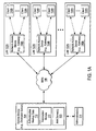
- FIGS. 1A and 1B are block diagrams of multiple local area networks, each having a gateway device, associated with an update device through a wide area network, according to one embodiment.
- FIG. 2 is a data interaction diagram between client devices, gateway devices, authentication servers, and the update device, according to one embodiment.
- FIG. 3 is a data interaction diagram illustrating an automatic broadcast of a master authentication mark-up data from an automation module in the update device to any number of local area networks, according to one embodiment.
- FIG. 4 is a process flow diagram of generating and associating the master authentication mark-up data across multiple local area networks, according to one embodiment.
- FIG. 5 is a process flow diagram of redirecting a user associated with the gateway device to the update device, according to one embodiment.
- FIGS. 6A-6D are examples of GUIs that may be used to configure an update device and/or gateway devices.
- FIGS. 7-8 and 9 A- 9 B are flow diagrams illustrating certain processes according to certain embodiments.
- FIGS. 10A-10F are examples of message formats in XML according to certain embodiments.
- FIG. 11 is a block diagram of a digital processing system which may be used with one embodiment of the invention.
- FIG. 1 is a block diagram of multiple first networks (e.g., local area networks or LANs) 102 A- 102 N, each having network access devices 100 A- 100 N (e.g., gateway devices), associated with an update device 104 through a second network (e.g., wide area network or WAN) 106 , according to one embodiment.
- a gateway device is used as an example of a network access device. However, it is not so limited. Other network access devices, such as, for example, a network router, etc., may be applied as well.
- a LAN is used as an example of a first network
- a WAN is used as an example of a second network
- other types of networks may also be applied.
- a first network may be a LAN (e.g., a department of an organization), while a second network may be an Intranet (e.g., a corporate network of the organization).
- update device 104 includes an automation module 110 and authentication mark-up data 112 , which may be stored in the update device 104 .
- the update device 104 may further includes an authentication, accounting, and authorization (AAA) server 120 according to one embodiment.
- AAA server 120 may be external to the update device 104 , such as, for example, coupled to the WAN 106 and may offer primarily authentication services or other services.
- the authentication mark-up data 112 is generated via a variety of ways, such as, for example, by an administrator (e.g., a network engineer) and/or automatically based upon at least one of a number of metrics (e.g., time of day sensitive, position sensitive, time of year sensitive, and/or an Enterprise Resource Planning (e.g., a ERP system such as OracleTM 11i) sensitive, etc.)
- a number of metrics e.g., time of day sensitive, position sensitive, time of year sensitive, and/or an Enterprise Resource Planning (e.g., a ERP system such as OracleTM 11i) sensitive, etc.
- the authentication mark-up data 112 may change depending upon whether the current season is spring or fall, and/or whether there is an overstock of a particular type of merchandise for sale. If the particular type of merchandise is overstocked, the authentication mark-up data 112 that is used to construct an authentication page may include a banner advertisement indicating a lower price generated by the ERP system, for example.
- the wide area network 106 connects the update device 104 to the multiple local area networks 102 A- 102 N.
- a local area network 102 A connects a gateway device 100 A to the update device 104 through the wide area network 106 .
- a local area network 102 B connects a gateway device 100 B to the update device 104 through the wide area network 106 .
- a local area network 102 N connects a gateway device 100 N to the update device 104 through the wide area network 106 .
- LANs 102 A- 102 N are shown in FIG. 1 are shown for the purposes of illustration only. More or less LANs may be implemented dependent upon specific network configurations.
- a secure connection is formed between at least one of the gateway devices 100 A- 100 N and the update device 104 using at least one of a virtual private network protocol (VPN), a hypertext transport protocol secure socket layer protocol (HTTPS), a fully qualified domain name protocol (FQDN), and at least one internet protocol (IP) address.
- VPN virtual private network protocol
- HTTPS hypertext transport protocol secure socket layer protocol
- FQDN fully qualified domain name protocol
- IP internet protocol
- an AAA server may be implemented internal or external to a gateway device, such as, for example, within any one of the gateway devices 100 A- 100 N.
- an AAA server may be external to the gateway device 100 B, and an AAA server may be inside the update device 104 is accessed by the gateway device 100 N through the wide area network 106 , according to the one embodiment.
- one or more AAA servers may be internal and/or external to any one of the gateway devices 100 A- 100 N, may be shared by multiple gateway devices 100 A- 100 N across any of the local area networks 102 A- 102 N, and/or the wide area network 106 .
- an AAA server may be implemented as a stand-alone server 120 coupled to the WAN 106 and accessible by gateway devices 100 A- 100 N. Further, some or all of the gateway devices 100 A- 100 N and the update device 104 may share the same authentication server(s), such as, for example, authentication server 120 . Other configurations may exist.
- any one of the networks 120 A- 120 N may be a wired or wireless network.
- a wireless network may be implemented as one of the variety of wireless technologies, such as, for example, Bluetooth, wireless local area network (WLAN) (e.g., IEEE 802.11 compatible network), infrared (IR), etc.
- WLAN wireless local area network
- IR infrared
- any one of clients 108 - 109 and 118 - 119 may be a wired or wireless device.
- anyone of the clients 108 - 109 and 118 - 119 may be a cellular telephone, personal digital assistant (PDA), a portable personal computer (PC), personal communicator (e.g., a two-way pager), or a combination of these.
- PDA personal digital assistant
- PC portable personal computer
- personal communicator e.g., a two-way pager
- FIG. 1B is a block diagram illustrating an example of network configuration according to an alternative embodiment.
- an authentication backend (ABE) is implemented as another LAN behind another network access device.
- ABE authentication backend
- each of the LANs 102 A- 102 N may be implemented as a WLAN and each of the gateway devices 100 A- 100 N may include an access point coupled or built-in in the respective gateway device.
- Other configurations may exist.
- FIG. 2 is a data interaction diagram between client devices 208 (e.g., may be similar to the client devices 108 in FIG. 1 ), gateway devices (a gateway device 100 A, a gateway device 100 B), authentication servers 120 , and the update device 104 , according to one embodiment.
- a client device 208 A associates (e.g., obtains an IP address from dynamic host control protocol (DHCP) and/or using a dynamic address translator (DAT)) with the gateway device 100 A.
- DHCP dynamic host control protocol
- DAT dynamic address translator
- a client device 208 B associates with the gateway device 100 B. Note that portions of the reference numbers are maintained identical with respect to FIG. 1 for the purposes of clearer illustration.
- the gateway device 100 A redirects the client device 208 A to the shared authentication page (e.g., using at least a portion of the authentication mark-up data 112 so that a user on the client device 208 A can be authenticated to access the wide area network 106 through the AAA server 120 ).
- the gateway device 100 B redirects the client device 208 B to the shared authentication page (e.g., using at least a portion of the authentication mark-up data 112 so that a user on the client device 208 B can be authenticated to access the wide area network 106 through the AAA server 120 ).
- a list of at least one defined internet protocol (IP) address and at least one port name is maintained on each of the gateway devices 100 A- 100 N to specify permitted communication channels between the gateway devices 100 A- 100 N and the update device 104 .
- the list includes a unique firewall identifier (e.g., an alphanumeric or numeric number, and/or a MAC address) of each of the gateway devices to further specify permitted communication channels.
- an authentication page is constructed and transmitted (e.g., pushed or multi-cast) from the update device 104 to the gateway device 100 A, the gateway device 100 B, as well as other gateway devices (not shown), and stored (e.g., cached) in each of the gateway devices.
- a query string having the unique firewall identifier may be hashed (e.g., a variable-sized amount of text may be converted into a fixed-sized output) to prevent tampering and least one of the gateway devices 100 A and 100 B may periodically request operational status of the update device 104 .
- the gateway devices 100 A and 100 B each perform a status check of the update device 104 (e.g., the update device 277 may be a web server optimized to host and manage one or more authentication pages).
- gateway device 100 A may perform the status check, and inform results of the status check to other gateway devices (e.g., across multiple LANs) using a particular protocol (e.g., STMP, HTTPS, etc.).
- the client device 208 A provides authentication information (e.g., a user of the client device 208 A may enter information such as name, date, credit card number, etc. in data entry fields visible on the shared authentication page) to the update device 104 .
- the client device 208 B provides authentication information to the update device 104 .
- the AAA server as a part of the ABE or alternatively accessible by the gateway device 100 A authenticates the client device 208 A (e.g., based upon a user ID and password entered into the client device 208 A by the user of the client device 208 A).
- an external AAA server coupled to the gateway device 100 B authenticates the client device 208 B.
- the client device 208 A is either permitted to access a desired location (e.g., a particular website and/or network) on the wide area network 106 , or denied access based upon results of the authentication performed by the AAA server 120 .
- the client device 208 B is either permitted to access a desired location (e.g., a particular website) on the wide area network 106 , or denied access based on results of the authentication performed by the AAA server 120 .
- the authentication mark-up data 112 is shared across multiple local area networks 102 A- 102 N.
- an administrator such as administrator 114 can centrally control the authentication markup data 112 which can then be propagated into one or more authentication pages used by one or more of the gateway devices 100 A- 100 N (e.g., the authentication mark-up data 112 for a variety of geographically dispersed retail branch locations).
- the authentication pages may be generated within the update device and transmitted to one or more gateway devices.
- each of the gateway devices may download the updated authentication markup data from the update device to construct a respective authentication page in response to a notification from the update device or by periodically polling the update device.
- the update device may directly host the authentication page(s) and accessible by some or all of the gateway devices.
- a bank having multiple retail branch locations across the world can quickly (e.g., by creating authentication mark-up data 112 on a central update device 104 ) and create a new authentication page to customers in various branch locations around the world.
- the update device 104 may have multiple different authentication pages using authentication mark-up data 112 , each designed specifically for certain retail locations, where at least two of the authentication pages share at least a portion of the authentication markup data.
- the update device 104 may decide which one of the multiple authentication pages or which portion of the authentication mark-up data 112 to select based upon a certain criteria of at least one of retail location, LAN, and or gateway device (e.g., based on country, geography, size of retail location, performance, etc.). For example, retail branch locations of the bank in Japan may display an authentication page written in Japanese, while retail branch locations of the bank in India may display an authentication page written in Hindi and/or English.
- FIG. 3 is a data interaction diagram illustrating an automatic transmission of authentication mark-up data (e.g., the authentication mark-up data 112 ) from an automation module (e.g., the automation module 110 ) in the update device 104 to any number of local area networks 102 A- 102 N, according to one embodiment.
- the administrator 300 e.g., a network administrator/engineer
- the automation module 110 transmits (e.g., individually or via multi-cast) the authentication mark-up data 112 (e.g., the shared authentication page) to various gateway devices in different local area networks 102 A- 102 N.
- a business having multiple locations can update an authentication page using some or all of the same authentication markup data across multiple local area networks.
- an administrator may centrally manage the authentication markup data used to construct authentication page(s). For example, a headquarter location of a coffee shop may disseminate a unique shared authentication page to all of its retail locations without requiring specially trained employees in each retail location to manually update authentication pages on their local gateway devices.
- FIG. 4 is a process flow diagram of generating and associating authentication mark-up data 112 across multiple local area networks (e.g., the gateway devices 100 of FIG. 1 ), according to one embodiment.
- process example 400 may be performed by an update device (e.g., update device 104 of FIG. 1 ).
- authentication mark-up data 112 is generated (e.g., by an administrator 300 of the update device 104 as described in FIG. 3 ), where the authentication markup date may be used to generate one or more authentication pages for different gateway devices of different LANs.
- At least a portion of the authentication mark-up data 112 is associated with each of the of gateway devices 100 A- 100 N based upon a decision criteria (e.g., based on a data of at least one of a plurality of retail locations associated with at least some of the plurality of gateway devices, wherein the data is chosen from a group comprising country, geography, size, and performance of at least some of the plurality of retail locations).
- a decision criteria e.g., based on a data of at least one of a plurality of retail locations associated with at least some of the plurality of gateway devices, wherein the data is chosen from a group comprising country, geography, size, and performance of at least some of the plurality of retail locations.
- the authentication mark-up data 112 is automatically associated with at least two of the gateway devices (e.g., using the automation module 110 of the update device 104 as described in FIG. 1 ) across multiple local area networks 102 A- 102 N (e.g., a particular gateway device 100 A may redirect a user of a client device 108 associated with the particular gateway device 100 A to the at least one master authentication mark-up data 112 ).
- At least one master authentication mark-up data 112 is stored in the update device 104 .
- a retry message may be displayed to the user when the at least one master authentication mark-up data 112 is unavailable and when a timer of at most 10 minutes has expired.
- the timer of at most 10 minutes ensures an optimum interval for ensuring that the master authentication mark-up data 112 has not gone stale for most common networking scenarios.
- a secure connection may be formed between at least some of the gateway devices 100 A- 100 N and the update device 104 using a variety of techniques set forth above.
- a query string having the unique firewall identifier may be hashed to prevent tampering.
- FIG. 5 is a process flow diagram of redirecting a user associated with a gateway device (e.g., the gateway device 100 A) to an update device (e.g., the update device 104 ), according to one embodiment.
- a gateway device receives a request from a client over a LAN for accessing a destination over a WAN, where the gateway device provides interface between the LAN and the WAN.
- a user is redirected from the gateway device 100 A to an authentication page created using authentication mark-up data 112 stored in the update device 104 .
- the authentication mark-up data 112 is shared among multiple gateway devices (e.g., the gateway device 100 A and the gateway device 100 N) across any number of local area networks 102 A- 102 N to generate one or more authentication pages for LANs 102 A- 102 N.
- the authentication page(s) may be hosted by an update device and/or a gateway device. However, the authentication page(s) may be created using the centralized stored and managed authentication markup data within the update device.
- an authentication facility e.g., an AAA server
- a user of the client may respond to the authentication page(s) to provide authentication information to the authentication facility, such as, for example, user name and password, etc.
- the authentication facility may be implemented within the update device or a gateway device.
- the authentication facility may be a stand-alone AAA server coupled to the WAN and shared by some or all of the gateway devices and/or the update device.
- a response to the authentication page(s) is received at the gateway device and forwarded from the gateway device to the client.
- a retry message may be displayed to the user when the at least one master authentication mark-up data 112 is unavailable and when a predetermined period of time (e.g., using a timer of at most 10 minutes) has expired. Other operations may also be performed.
- the communications mechanisms between a gateway device and an update device can be applied to an update device of a wired network and one or more gateway devices of wireless networks.
- the communications mechanisms set forth above may also be referred to as Lightweight Hotspot Messaging (LHM) which defines the method and syntax for communications between wireless gateway device, such as, for example, a SONICWALL wireless access device (e.g., a SOHO TZW, a TZ170 Wireless, or a SonicPoint with a governing SONICWALL security appliance) and an Authentication Back-End (ABE) for the purpose of authenticating Hotspot users and providing them parametrically bound network access.
- LHM Lightweight Hotspot Messaging
- ABE Authentication Back-End
- a SONICWALL wireless platform or a SONICWALL security appliance may be used as an example of a gateway device and a Web server is used as an example of an update device.
- a Web server is used as an example of an update device.
- other types of gateway devices and update devices may be applied.
- LHM allows network operators to provide centralized management of multiple Hotspot locations by providing an interface between SONICWALL's Wireless Guest Services and any existing ABE.
- LHM is an adaptation of the generalized WISPr and GIS specifications. LHM was designed to satisfy the requirements of a particularly common operational environment rather than a broad set of environments. Specifically, according to one embodiment, LHM allows for Hotspot user-management and authentication to occur entirely on the network operator's ABE, supporting any method of account creation and management, and any extent of site customization and branding. This approach enables integration into any existing environment without dependencies upon particular billing, accounting or database systems, and also provides the network operator with unrestricted control of the site's design, from look-and-feel to redirection.
- an ABE includes a Web Server (WS) to host content for user interaction and an (optional) Authentication Server (AS) to provide directory services authentication, for example, as shown in FIG. 1B .
- the AS can be any kind of user database, including, but not limited to RADIUS, LDAP, or AD. It is appreciated that the WS can communicate with the AS for authentication purposes.
- the WS and AS can be administered on a single server or on separate servers.
- LHM also provides the ability for the AS to use the SONICWALL security appliance's internal user database for user authentication.
- the ABE may need to communicate with the Hotspot SONICWALL to exchange result codes and session information.
- Most of the communications may be HTTPS and can occur either directly (such as to the LAN, WAN, X0 interface of the SONICWALL security appliance) or over a VPN tunnel to one of the SONICWALL security appliance's management interface addresses.
- the LHM management interface may be selectable and the selected interface will accept LHM management messaging through automatically added access rules.
- LHM communications may occur on a specific LHM management port that may be defined on the SONICWALL security appliance, and the LHM management port may be different from the standard HTTPS Management port.
- a list of IP addresses may also be defined on the SONICWALL security appliance specifying the IP addresses LHM management communications will allow.
- two parameters may be constructed by the SONICWALL and passed to the ABE.
- the following communication parameters may be used for communications between the ABE and the SONICWALL.
- the parameter values set forth above may be passed to the ABE by the SONICWALL during Session Creation operations and during the Session State Sync (see the Message Format section), and they may be used by the ABE as a basis in the construction of some or all of the relevant URL's.
- the following are the pages on the SONICWALL that may be referenced by the ABE:
- URLs hosted on the ABE may be fully configurable at the SONICWALL, for example, via GUIs shown in FIGS. 6A and 6B .
- the host can be specified using either an IP address or FQDN.
- FQDN the name may be resolved upon first use and will be stored by the SONICWALL as an IP address. Additional information may also be configured, for example, via GUI shown in FIG. 6D .
- the phases of a session lifecycle include the following sections:
- FIG. 7 is a flow diagram illustrating an example of a session creation according to one embodiment. As shown in FIG. 7 , a session creation may include the following operations:
- sessions may be managed via a Session Popup window. This should be a browser window instantiated at the time of Session Creation providing session time information (e.g. lifetime, idle timeout value, timer countdowns, etc.) and a “Logout” button. Sample code will be provided.
- FIG. 8 is a flow diagram illustrating an example of an idle timeout process according to one embodiment. As shown in FIG. 8 , an idle timeout process may include the following operations:
- FIG. 9A is a flow diagram illustrating an example of a user logout process according to one embodiment.
- a user logout process may include, but is not limited to, the following operations:
- FIG. 9B is a flow diagram illustrating an example of an administrator logout process according to one embodiment.
- an administrator logout process may include, but is not limited to, the following operations:
- the SONICWALL can optionally send, for example, a secure HTTP GET operation to the WS in order to determine server operational status.
- the target URL will be configurable, as will the interval of the query (e.g., between 1 and 60 minutes).
- the WS responds back in an XML format listing the server's current state. Refer to Message Format section for details.
- the SONICWALL logs the response and redirects all subsequent authentication requests to an internal “wirelessServicesUnavailable.html” page. This page will provide administrator configurable text explaining recourse. The SONICWALL will continue to attempt to query the ABE at the configured interval and will resume redirection to the WS (rather than to the wirelessServicesUnavailable.html page) when a response code of 0 (‘Server Up’) is received.
- an error response code e.g., 1, 2, or 255
- the SONICWALL logs the response and redirects all subsequent authentication requests to an internal “wirelessServicesUnavailable.html” page. This page will provide administrator configurable text explaining recourse. The SONICWALL will continue to attempt to query the ABE at the configured interval and will resume redirection to the WS (rather than to the wirelessServicesUnavailable.html page) when a response code of 0 (‘Server Up’) is received.
- the SONICWALL may optionally send, for example, a secure HTTP POST operation to the WS containing an XML list of some or all currently active guest sessions:
- Message authentication feature ensures that the CGI data exchanged between both the SONICWALL and ABE originated from the SONICWALL/ABE device, and that it has not been tampered with. If enabled, an additional CGI parameter named “hmac” will be added to all CGI data exchanged. The following is an example of what the redirect URL now looks like with message authentication enabled:
- the SONICWALL device will expect an HMAC signature as part of the CGI post data originating from the ABE. If the SONICWALL detects that the HMAC is missing or incorrect, then an error code of 251 is returned, and the requested operation (e.g. guest login, account creation, etc) is aborted.
- an external authentication request may be sent via a secure HTTP POST operation, where the POST parameters may include the following:
- an external authentication response may be an XML (extensible markup language) response, similar to those shown in FIG. 10A , where the (response code) includes, but is not limited to, one of the values listed in the following table:
- a local authentication request may be sent via a secure HTTP POST operation, where the POST parameters may include the following:
- a local authentication response may be an XML (extensible markup language) response, similar to those shown in FIG. 10A , where the (response code) includes, but is not limited to, one of the values listed in the following table:
- a logoff request may be sent via a secure HTTP POST operation, where the POST parameters may include the following:
- a logoff response in response to the logoff request set forth above, may be an XML (extensible markup language) response, similar to those shown in FIG. 10B , where the (response code) includes, but is not limited to, one of the values listed in the following table:
- a response in response to a WS server status check, a response may be returned in an XML response, similar to the one shown in FIG. 10C , where the ⁇ response code ⁇ includes, but is not limited to, one of the values listed in the following table:
- a gateway device may send session state synchronization request via a secure HTTP POST operation to the AS containing an XML list of all currently active guest sessions similar to the one shown in FIG. 10D .
- Both the target URL and time period will be configurable by the GW admin.
- the CGI post parameters includes the following argument:
- an XML response may be returned similar to the one shown in FIG. 10E , where the response code may be one of the values listed in the following table:
- a WS sends local account creation request via a secure HTTP POST operation, where the POST parameters include, but is not limited to, the following arguments:
- a local account creation reply may be returned in an XML format, similar to the one shown in FIG. 10F , where the (response code) may include, but is not limited to, one of the values listed in the following table:
- FIG. 11 is a block diagram of a digital processing system which may be used with one embodiment of the invention.
- the system 1100 shown in FIG. 11 may be used as a client computer system ( 108 A- 108 N of FIG. 1A ).
- the exemplary system 1100 may be implemented as a network access device described above and/or a wireless access point.
- the exemplary computer system 1100 may be implemented as an update device described above.
- FIG. 11 illustrates various components of a computer system, it is not intended to represent any particular architecture or manner of interconnecting the components, as such details are not germane to the present invention. It will also be appreciated that network computers, handheld computers, cell phones, and other data processing systems which have fewer components or perhaps more components may also be used with the present invention.
- the computer system 1100 which is a form of a data processing system, includes a bus 1102 which is coupled to a microprocessor 1103 and a ROM 11011 , a volatile RAM 1105 , and a non-volatile memory 1106 .
- the microprocessor 1103 which may be, for example, a PowerPC G4 or PowerPC G5 microprocessor from Motorola, Inc. or IBM, is coupled to cache memory 1104 as shown in the example of FIG. 11 .
- the bus 1102 interconnects these various components together and also interconnects these components 1103 , 11011 , 1105 , and 1106 to a display controller and display device 1108 , as well as to input/output (I/O) devices 1110 , which may be mice, keyboards, modems, network interfaces, printers, and other devices which are well-known in the art.
- I/O input/output
- the input/output devices 1110 are coupled to the system through input/output controllers 1109 .
- the volatile RAM 1105 is typically implemented as dynamic RAM (DRAM) which requires power continuously in order to refresh or maintain the data in the memory.
- DRAM dynamic RAM
- the non-volatile memory 1106 is typically a magnetic hard drive, a magnetic optical drive, an optical drive, or a DVD RAM or other type of memory system which maintains data even after power is removed from the system.
- the non-volatile memory will also be a random access memory, although this is not required.
- FIG. 11 shows that the non-volatile memory is a local device coupled directly to the rest of the components in the data processing system, it will be appreciated that the present invention may utilize a non-volatile memory which is remote from the system, such as a network storage device which is coupled to the data processing system through a network interface such as a modem or Ethernet interface.
- the bus 1102 may include one or more buses connected to each other through various bridges, controllers, and/or adapters, as is well-known in the art.
- the I/O controller 1109 includes a USB (Universal Serial Bus) adapter for controlling USB peripherals.
- I/O controller 1109 may include an IEEE-1394 adapter, also known as FireWire adapter, for controlling FireWire devices.
- Other components may also be included.
- authentication mark-up data of multiple local area networks has been described herein. It will be appreciated that some or all of the operations described above, for example, operations involved in FIGS. 2-5 , 7 - 8 , and 9 A- 9 B, may be performed by processing logic that may include hardware (e.g., circuitry, dedicated logic, etc.), software (such as is run on a general-purpose computer system, a server, a router, or a dedicated machine), or a combination of both.
- processing logic may include hardware (e.g., circuitry, dedicated logic, etc.), software (such as is run on a general-purpose computer system, a server, a router, or a dedicated machine), or a combination of both.
- Embodiments of the present invention also relate to an apparatus for performing the operations herein.
- This apparatus may be specially constructed for the required purposes, or it may comprise a general-purpose computer selectively activated or reconfigured by a computer program stored in the computer.
- a computer program may be stored in a computer readable storage medium, such as, but is not limited to, any type of disk including floppy disks, optical disks, CD-ROMs, and magnetic-optical disks, read-only memories (ROMs), random access memories (RAMs), erasable programmable ROMs (EPROMs), electrically erasable programmable ROMs (EEPROMs), magnetic or optical cards, or any type of media suitable for storing electronic instructions, and each coupled to a computer system bus.
- ROMs read-only memories
- RAMs random access memories
- EPROMs erasable programmable ROMs
- EEPROMs electrically erasable programmable ROMs
- magnetic or optical cards or any type of media suitable for storing electronic
- a machine-readable medium may include any mechanism for storing or transmitting information in a form readable by a machine (e.g., a computer).
- a machine-readable medium includes read only memory (“ROM”); random access memory (“RAM”); magnetic disk storage media; optical storage media; flash memory devices; electrical, optical, acoustical or other form of propagated signals (e.g., carrier waves, infrared signals, digital signals, etc.); etc.
Abstract
Description
-
- A management base URL (universal resource locator) (e.g., baseMgmtUrl)—The IP address and the port that the ABE uses to communicate with the SONICWALL. It will be composed of the HTTPS protocol designator, the IP of the selected LHM management interface, and the LHM port.
- A client redirect URL (e.g., clientRedirectUrl)—The IP address (and optionally the port) on the SONICWALL to which clients will be redirected during various phases of the session, i.e. the LAN management IP on the TZW, or the WLAN IP on a SonicOS Enhanced device.
-
- A service unavailable page (e.g., wirelessServicesUnavailable.html)—ABE is unavailable message. This redirection will typically be sent by the SONICWALL, but can also be referenced by the ABE. Text is configurable, for example, via a GUI (graphical user interface) shown in
FIG. 6C . - An external guest redirect page (e.g., externalGuestRedirect.html)—Initial redirect message provided by the SONICWALL on session creation. Text is configurable, for example, via the GUI shown in
FIG. 6C . - An external guest login page (e.g., externalGuestLogin.cgi)—The page to which the ABE POSTs session creation data.
- An external guest logoff page (e.g., externalGuestLogoff.cgi)—The page to which the ABE POSTs session termination data.
- A local guest login page (e.g., localGuestLogin.cgi)—The page to which the ABE POSTs for authenticating user credentials against the SONICWALL's internal user database.
- A guest create account page (e.g., createGuestAccount.cgi)—The page to which the ABE POSTs to create a guest account in the SONICWALL's internal user database.
- A service unavailable page (e.g., wirelessServicesUnavailable.html)—ABE is unavailable message. This redirection will typically be sent by the SONICWALL, but can also be referenced by the ABE. Text is configurable, for example, via a GUI (graphical user interface) shown in
-
- Session Creation
- Session Window Popup
- Idle Timeout
- Session Timeout
- User Logout
- Administrator Logout
- WS Server Status Check
- Session State Sync
- Session Creation
-
- 1. Wireless client associates with SONICWALL and obtains IP Address from internal DHCP server, or uses static addressing with Dynamic Address Translation (DAT) feature.
- 2. Client requests web-resource (e.g., http://www.website.com)
- a. SONICWALL determines that this is a new session.
- 3. SONICWALL redirects client to internally hosted externalGuestRedirect.html page. The externalGuestRedirect.html page provides administrator configurable text explaining that the session is being redirected for authentication.
- 4. During this redirect, the SONICWALL determines the availability of the ABE (e.g., via a JavaScript redirect attempt to the configured target redirect page).
- a. If the redirect to the WS fails to occur within a specified period (the value will be configurable on the SONICWALL, such as, for example, between 1 and 30 seconds) the SONICWALL will redirect the session the internal “wirelessServicesUnavailable.html” page.
- 5. In addition to the availability check, an optional full “WS Server Status Check” may be available from the SONICWALL. This option can be configured to run at a configurable interval, such as, for example, between 1 and 60 minutes. In the event of an error response code (e.g., 1, 2, or 255), the SONICWALL may log the response and will redirect the browser to the internal “wirelessServicesUnavailable.html” page. This page will provide administrator configurable text explaining recourse.
- 6. If available, the SONICWALL redirects client to authentication portal hosted on AS such as, for example, at:
- https://172.20.0.1/auth.html?sessId=11aa::00ff&ip=172.16.31.10mac=0002AB CDEF&req=http://www.website.com&ufi=0006010203&baseMgmtUrl=https://10.1.2.3:4043&clientRedirectUrl=http://172.16.31.1, where
- a. “sessId”—A 32 byte hex representation of a 16 byte MD5 hash value generated by the SONICWALL, which will be used by the SONICWALL and the WS for indexing clients (e.g. “11aa3e2f5da3e12ef978ba120d2300ff”).
- b. “ip”—The client IP address.
- c. “mac” is the client MAC address.
- d. “req”—The originally requested web-site is passed as an argument to the authentication server)
- e. “ufi”—The SONICWALL Unique Firewall Identifier. To be used for site identification, if desired.
- f. “baseMgmtUrl”—The protocol, IP address, and port on the SONICWALL with which the IP will subsequently communicate.
- g. “clientRedirectUrl”—The protocol, IP address (and optionally port) on the SONICWALL that the ABE will use for client redirection.
- 7. Client provides authentication information (e.g. username, password, token, etc.).
- 8. WS validates user against AS, where
- a. AS provides session specific information, namely, Session Timeout and Idle Timeout values.
- b. Session specific values can optionally be applied globally by the WS rather than obtained from the AS; some value simply needs to be passed to the SONICWALL.
- c. Timeout values will be presented in seconds and can range from, for example, 1 to 863,913,600 (equal to 9999 days).
- 9. If authentication fails, the WS should redirect the client to a page explaining the failure. A link should be provided back to the externalGuestRedirect.html to restart the process.
- 10. If successful, the WS connects to the SONICWALL either via HTTPS or via VPN and POSTs, for example, at:
- https://10.1.2.3:4043/externalGuestLogin.cgi?sessId=11aa::00ff&userName=Name&sessionLifetime=1800&idleTimeout=600
- a. The SONICWALL may attempt to create the session and will send a result to the WS in the same connection.
- 11. If failure response is received (e.g. code 51, 100, or 255), WS may redirect client to a page explaining the failure. A link can be provided back to externalGuestRedirect.html to start process over.
- 12. If successful (e.g., code 50), WS can redirect user to the originally requested site (req) or to any site (e.g. a portal or start page). WS may also instruct on how to logoff from session (e.g. bookmark a page, popup window, URL, etc.).
-
- Clicking the “Logout” button ends the session and triggers a “User Logout” event.
- Attempting to close the window should provide a warning message that closing the window will end the session.
- Closing the window ends the session and triggers a “User Logout” event.
-
- 1. Idle timer (e.g., as set during Session Creation) expires.
- 2. Since the client's browser may not be open at this time, the SONICWALL sends a POST to the WS at, for example, https://172.20.0.1/logout.html?sessId=11aa::00ff&eventId=4.
- a. The resource to which the POST will be sent will be configurable on the SONICWALL.
- b. The WS hosted page must expect and interpret the sessId and eventId values.
- 3. The WS will send an XML result to the WS in the same connection.
- 4. If the client returns from the idle state and attempts to reach a web resource, the SONICWALL will redirect the user to the internal externalGuestRedirect.html page, starting the Session Creation process over.
Similarly, a session timeout event occurs when the Session lifetime expires. The exchange is the same as the Idle Timeout above, except the Session Timeout eventId value is “3” (instead of “4” for an Idle Timeout).
-
- 1. Client logs out using, or closes the session popup window.
- 2. The WS sends a POST to, for example, https://10.1.2.3:4043/externalGuestLogoff.cgi?sessId=11aa::00ff&eventId=1. (see “Message Format” section for Logoff event ID's).
- a. “sessId”—The value generated during Session Creation by the SONICWALL, which is used by the SONICWALL and the WS for indexing clients.
- b. “eventId”—Describes the logoff request event.
- 3. The SONICWALL responds with a result to the WS in the same connection.
- 4. If the client attempts to reach a web resource, the SONICWALL will redirect the user to the externalGuestRedirect.html page, starting the Session Creation process over.
-
- 1. ABE administrator terminates the Guest session from the management UI.
- 2. The WS sends a POST to the SONICWALL, for example, https://10.1.2.3:4043/externalGuestLogoffcgi?sessId=11aa::00ff&eventId=2.
- a. “sessId”—The value generated during Session Creation by the SONICWALL, which is used by the SONICWALL and the WS for indexing clients.
- b. “eventId”—Describes the logoff request event.
- 3. The SONICWALL sends a result to the WS in the same connection. Results are described in the Message Format—Logoff Reply section.
- 4. If the client returns from the idle state and attempts to reach a web resource, the SONICWALL redirects the user to the externalGuestRedirect.html page, starting the Session Creation process over.
-
- The feature itself will be enabled via a checkbox on the SONICWALL and will be disabled by default.
- The target URL will be configurable.
- The CGI post will provide the “sessionList” as an XML list of all active guest sessions.
-
- https://10.1.2.3/login.asp?sessionId=faad7f12ac26d5c2fe3236de2c149a22&ip=172.16.31.2&mac=00:90:4b:6a:37:32&ufi=0006B1020148&mgmtBaseUrl=https://10.0.61.222:4043/&clientRedirectUrl=http://192.168.168.168:80/&req=http://www.google.com/&hmac=cd2399aeff26d5c2fe3236d211549acc
In the above-example, the HMAC signature was generated using the following data structure: - HMAC(
- faad7f12ac26d5c2fe3236de2c149a22+
- 172.16.31.2+
- 00:90:4b:6a:37:32+
- 0006B1020148+
- https://10.0.61.222:4043/+
- https://10.0.61.222:4043/+
- http://www.google.com/
- https://10.1.2.3/login.asp?sessionId=faad7f12ac26d5c2fe3236de2c149a22&ip=172.16.31.2&mac=00:90:4b:6a:37:32&ufi=0006B1020148&mgmtBaseUrl=https://10.0.61.222:4043/&clientRedirectUrl=http://192.168.168.168:80/&req=http://www.google.com/&hmac=cd2399aeff26d5c2fe3236d211549acc
-
- sessId: Session ID
- userName: The full user ID
- sessionLifetime: The session lifetime of the user (in seconds)
- idleTimeout: The max idle timeout (in seconds)
| Response Code | Response Meaning |
| 50 | Login succeeded |
| 51 | Session limit exceeded |
| 100 | Login failed -- access reject |
| 251 | Msg. Auth failed -- Invalid HMAC |
| 253 | Invalid session ID |
| 254 | Invalid or missing CGI parameter |
| 255 | Internal error |
-
- sessId: Session ID
- userName: The full user ID
- passwd: The guest's clear-text password
| Response Code | Response Meaning |
| 50 | Login succeeded |
| 51 | Session limit exceeded |
| 52 | Invalid username/password |
| 100 | Login failed -- access reject |
| 251 | Msg. Auth failed -- Invalid HMAC |
| 253 | Invalid session ID |
| 254 | Invalid or missing CGI parameter |
| 255 | Internal error |
-
- sessId: GW Session ID
- eventId: Logoff event ID may be one of the following:
| Logoff Event | Event Meaning | |
| 1 | Guest logged out manually |
| 2 | Admin logged off the specified |
| 3 | Guest session expired |
| 4 | Guest idle timeout expired |
| Response Code | Response Meaning |
| 150 | Logoff succeeded |
| 251 | Msg. Auth failed -- Invalid HMAC |
| 253 | Invalid session ID |
| 254 | Invalid or missing CGI parameter |
| 255 | Internal error |
| Response Code | Response Meaning |
| 0 | Server Up |
| 1 | DB down |
| 2 | Configuration error |
| 255 | Internal error |
-
- sessionList: XML list of all active GW guest sessions.
| Response Code | Response Meaning |
| 200 | Sync successful |
| 201 | Sync failed |
| 255 | Internal error |
-
- userName: The full user id (max length: 32)
- passwd: The guest's clear-text password (max length: 64)
- comment: Optional (max length: 16). Default=NULL
- enforceUniqueLogin: Optional: 1=true, 0=false. Default=1
- activateNow: Optional: 1=true, 0=false. Default=0
- autoPrune: Optional: 1=true, 0=false. Default=1
- accountLifetime: The account lifetime of the user (expressed in seconds)
- sessionLifetime: The session lifetime of the user (expressed in seconds)
- idleTimeout: The max idle timeout (expressed in seconds)
| Response Code | Response Meaning |
| 10 | Account creation succeeded |
| 11 | Max account limit |
| 12 | Account Exists |
| 251 | Msg. Auth failed -- Invalid HMAC |
| 254 | Invalid or missing CGI parameter |
| 255 | Internal error |
Claims (24)
Priority Applications (1)
| Application Number | Priority Date | Filing Date | Title |
|---|---|---|---|
| US11/118,506 US8074259B1 (en) | 2005-04-28 | 2005-04-28 | Authentication mark-up data of multiple local area networks |
Applications Claiming Priority (1)
| Application Number | Priority Date | Filing Date | Title |
|---|---|---|---|
| US11/118,506 US8074259B1 (en) | 2005-04-28 | 2005-04-28 | Authentication mark-up data of multiple local area networks |
Publications (1)
| Publication Number | Publication Date |
|---|---|
| US8074259B1 true US8074259B1 (en) | 2011-12-06 |
Family
ID=45034536
Family Applications (1)
| Application Number | Title | Priority Date | Filing Date |
|---|---|---|---|
| US11/118,506 Active 2028-10-01 US8074259B1 (en) | 2005-04-28 | 2005-04-28 | Authentication mark-up data of multiple local area networks |
Country Status (1)
| Country | Link |
|---|---|
| US (1) | US8074259B1 (en) |
Cited By (16)
| Publication number | Priority date | Publication date | Assignee | Title |
|---|---|---|---|---|
| US20080060064A1 (en) * | 2006-09-06 | 2008-03-06 | Devicescape Software, Inc. | Systems and methods for obtaining network access |
| US20100095359A1 (en) * | 2008-10-13 | 2010-04-15 | Devicescape Software, Inc. | Systems and Methods for Identifying a Network |
| US20100154038A1 (en) * | 2008-12-17 | 2010-06-17 | International Business Machines Corporation | Dynamic File Access To Files Of Unmapped Remote Computers |
| US20100263022A1 (en) * | 2008-10-13 | 2010-10-14 | Devicescape Software, Inc. | Systems and Methods for Enhanced Smartclient Support |
| US20110047603A1 (en) * | 2006-09-06 | 2011-02-24 | John Gordon | Systems and Methods for Obtaining Network Credentials |
| US20110106708A1 (en) * | 2009-10-30 | 2011-05-05 | Ncr Corporation | Techniques for temporary access to enterprise networks |
| US20120124646A1 (en) * | 2008-12-19 | 2012-05-17 | Lin Paul Y | Method and Apparatus for Authenticating Online Transactions Using a Browser |
| US8554830B2 (en) | 2006-09-06 | 2013-10-08 | Devicescape Software, Inc. | Systems and methods for wireless network selection |
| US8667596B2 (en) | 2006-09-06 | 2014-03-04 | Devicescape Software, Inc. | Systems and methods for network curation |
| US20150181377A1 (en) * | 2005-10-21 | 2015-06-25 | Cisco Technology, Inc. | Support for wispr attributes in a tal/car pwlan environment |
| US9326138B2 (en) | 2006-09-06 | 2016-04-26 | Devicescape Software, Inc. | Systems and methods for determining location over a network |
| WO2010070456A3 (en) * | 2008-12-19 | 2017-04-06 | F2Ware Inc. | Method and apparatus for authenticating online transactions using a browser |
| US20170134367A1 (en) * | 2012-08-23 | 2017-05-11 | Amazon Technologies, Inc. | Adaptive timeouts for security credentials |
| US20180124051A1 (en) * | 2016-07-14 | 2018-05-03 | Huawei Technologies Co., Ltd. | Response Method and System in Virtual Network Computing Authentication, and Proxy Server |
| US20190268307A1 (en) * | 2018-02-26 | 2019-08-29 | Mcafee, Llc | Gateway with access checkpoint |
| US11863631B1 (en) * | 2023-02-23 | 2024-01-02 | Cisco Technology, Inc. | Secure access App Connectors |
Citations (10)
| Publication number | Priority date | Publication date | Assignee | Title |
|---|---|---|---|---|
| US20020021665A1 (en) * | 2000-05-05 | 2002-02-21 | Nomadix, Inc. | Network usage monitoring device and associated method |
| US20020066033A1 (en) * | 2000-07-31 | 2002-05-30 | Dobbins Kurt A. | Managing content resources |
| US6636894B1 (en) * | 1998-12-08 | 2003-10-21 | Nomadix, Inc. | Systems and methods for redirecting users having transparent computer access to a network using a gateway device having redirection capability |
| US6789110B1 (en) * | 1999-10-22 | 2004-09-07 | Nomadix, Inc. | Information and control console for use with a network gateway interface |
| US6839842B1 (en) | 1996-12-27 | 2005-01-04 | Intel Corporation | Method and apparatus for authenticating information |
| US6847995B1 (en) | 2000-03-30 | 2005-01-25 | United Devices, Inc. | Security architecture for distributed processing systems and associated method |
| US6851051B1 (en) | 1999-04-12 | 2005-02-01 | International Business Machines Corporation | System and method for liveness authentication using an augmented challenge/response scheme |
| US20050027837A1 (en) | 2003-07-29 | 2005-02-03 | Enterasys Networks, Inc. | System and method for dynamic network policy management |
| US6857073B2 (en) | 1998-05-21 | 2005-02-15 | Equifax Inc. | System and method for authentication of network users |
| US20060264201A1 (en) * | 2003-03-10 | 2006-11-23 | Thomson Licensing S.A. | Identity mapping mechanism in wlan access control with public authentication servers |
-
2005
- 2005-04-28 US US11/118,506 patent/US8074259B1/en active Active
Patent Citations (10)
| Publication number | Priority date | Publication date | Assignee | Title |
|---|---|---|---|---|
| US6839842B1 (en) | 1996-12-27 | 2005-01-04 | Intel Corporation | Method and apparatus for authenticating information |
| US6857073B2 (en) | 1998-05-21 | 2005-02-15 | Equifax Inc. | System and method for authentication of network users |
| US6636894B1 (en) * | 1998-12-08 | 2003-10-21 | Nomadix, Inc. | Systems and methods for redirecting users having transparent computer access to a network using a gateway device having redirection capability |
| US6851051B1 (en) | 1999-04-12 | 2005-02-01 | International Business Machines Corporation | System and method for liveness authentication using an augmented challenge/response scheme |
| US6789110B1 (en) * | 1999-10-22 | 2004-09-07 | Nomadix, Inc. | Information and control console for use with a network gateway interface |
| US6847995B1 (en) | 2000-03-30 | 2005-01-25 | United Devices, Inc. | Security architecture for distributed processing systems and associated method |
| US20020021665A1 (en) * | 2000-05-05 | 2002-02-21 | Nomadix, Inc. | Network usage monitoring device and associated method |
| US20020066033A1 (en) * | 2000-07-31 | 2002-05-30 | Dobbins Kurt A. | Managing content resources |
| US20060264201A1 (en) * | 2003-03-10 | 2006-11-23 | Thomson Licensing S.A. | Identity mapping mechanism in wlan access control with public authentication servers |
| US20050027837A1 (en) | 2003-07-29 | 2005-02-03 | Enterasys Networks, Inc. | System and method for dynamic network policy management |
Non-Patent Citations (2)
| Title |
|---|
| B. Anton (Gemtek Systems, Inc.), B. Bullock (iPass, Inc.), J. Short (Nomadix, Inc.), Titled: "Best Current Practices for Wireless Internet Service Provider (WISP) Roaming", Feb. 2003, pp. 1-37. |
| Jeff Edgett & Roy Albert (iPass Inc.), Titled: "Generic Interface Specification White Paper", 2003, pp. 1-9, www.ipass.com. |
Cited By (29)
| Publication number | Priority date | Publication date | Assignee | Title |
|---|---|---|---|---|
| US20150181377A1 (en) * | 2005-10-21 | 2015-06-25 | Cisco Technology, Inc. | Support for wispr attributes in a tal/car pwlan environment |
| US9877147B2 (en) * | 2005-10-21 | 2018-01-23 | Cisco Technology, Inc. | Support for WISPr attributes in a TAL/CAR PWLAN environment |
| US9913303B2 (en) | 2006-09-06 | 2018-03-06 | Devicescape Software, Inc. | Systems and methods for network curation |
| US8549588B2 (en) | 2006-09-06 | 2013-10-01 | Devicescape Software, Inc. | Systems and methods for obtaining network access |
| US8743778B2 (en) | 2006-09-06 | 2014-06-03 | Devicescape Software, Inc. | Systems and methods for obtaining network credentials |
| US9326138B2 (en) | 2006-09-06 | 2016-04-26 | Devicescape Software, Inc. | Systems and methods for determining location over a network |
| US20080060064A1 (en) * | 2006-09-06 | 2008-03-06 | Devicescape Software, Inc. | Systems and methods for obtaining network access |
| US20110047603A1 (en) * | 2006-09-06 | 2011-02-24 | John Gordon | Systems and Methods for Obtaining Network Credentials |
| US8667596B2 (en) | 2006-09-06 | 2014-03-04 | Devicescape Software, Inc. | Systems and methods for network curation |
| US8554830B2 (en) | 2006-09-06 | 2013-10-08 | Devicescape Software, Inc. | Systems and methods for wireless network selection |
| US8353007B2 (en) | 2008-10-13 | 2013-01-08 | Devicescape Software, Inc. | Systems and methods for identifying a network |
| US20100263022A1 (en) * | 2008-10-13 | 2010-10-14 | Devicescape Software, Inc. | Systems and Methods for Enhanced Smartclient Support |
| US20100095359A1 (en) * | 2008-10-13 | 2010-04-15 | Devicescape Software, Inc. | Systems and Methods for Identifying a Network |
| US20100154038A1 (en) * | 2008-12-17 | 2010-06-17 | International Business Machines Corporation | Dynamic File Access To Files Of Unmapped Remote Computers |
| US9577998B2 (en) * | 2008-12-17 | 2017-02-21 | International Business Machines Corporation | Dynamic file access to files of unmapped remote computers |
| US20120124646A1 (en) * | 2008-12-19 | 2012-05-17 | Lin Paul Y | Method and Apparatus for Authenticating Online Transactions Using a Browser |
| US20120131332A1 (en) * | 2008-12-19 | 2012-05-24 | Lin Paul Y | Method and Apparatus for Authenticating Online Transactions Using a Browser |
| WO2010070456A3 (en) * | 2008-12-19 | 2017-04-06 | F2Ware Inc. | Method and apparatus for authenticating online transactions using a browser |
| US8528076B2 (en) * | 2008-12-19 | 2013-09-03 | F2Ware, Inc. | Method and apparatus for authenticating online transactions using a browser and a secure channel with an authentication server |
| US8290877B2 (en) * | 2009-10-30 | 2012-10-16 | Ncr Corporation | Techniques for temporary access to enterprise networks |
| US20110106708A1 (en) * | 2009-10-30 | 2011-05-05 | Ncr Corporation | Techniques for temporary access to enterprise networks |
| US20170134367A1 (en) * | 2012-08-23 | 2017-05-11 | Amazon Technologies, Inc. | Adaptive timeouts for security credentials |
| US10652232B2 (en) * | 2012-08-23 | 2020-05-12 | Amazon Technologies, Inc. | Adaptive timeouts for security credentials |
| US20180124051A1 (en) * | 2016-07-14 | 2018-05-03 | Huawei Technologies Co., Ltd. | Response Method and System in Virtual Network Computing Authentication, and Proxy Server |
| US11140162B2 (en) * | 2016-07-14 | 2021-10-05 | Huawei Technologies Co., Ltd. | Response method and system in virtual network computing authentication, and proxy server |
| US20190268307A1 (en) * | 2018-02-26 | 2019-08-29 | Mcafee, Llc | Gateway with access checkpoint |
| US10728218B2 (en) * | 2018-02-26 | 2020-07-28 | Mcafee, Llc | Gateway with access checkpoint |
| US11558355B2 (en) * | 2018-02-26 | 2023-01-17 | Mcafee, Llc | Gateway with access checkpoint |
| US11863631B1 (en) * | 2023-02-23 | 2024-01-02 | Cisco Technology, Inc. | Secure access App Connectors |
Similar Documents
| Publication | Publication Date | Title |
|---|---|---|
| US8074259B1 (en) | Authentication mark-up data of multiple local area networks | |
| US9913303B2 (en) | Systems and methods for network curation | |
| US9801071B2 (en) | Systems and methods for enhanced engagement | |
| US8990911B2 (en) | System and method for single sign-on to resources across a network | |
| US8365258B2 (en) | Multi factor authentication | |
| JP2019204519A (en) | Portal authentication | |
| CN102316153B (en) | VPN network client for mobile device having dynamically constructed display for native access to web mail | |
| US20060136724A1 (en) | Relay method of encryption communication, gateway server, and program and program memory medium of encryption communication | |
| US20120017268A9 (en) | Enhanced multi factor authentication | |
| US20130246504A1 (en) | Method for subscribing to notification, apparatus and system | |
| JP2012515956A (en) | System and method for enhanced smart client support | |
| US8201226B2 (en) | Authorizing network access based on completed educational task | |
| CN102316093A (en) | The double mode many service VPN networking clients that are used for mobile device | |
| WO2008030525A2 (en) | Systems and methods for providing network credentials | |
| EP2997711B1 (en) | Providing single sign-on for wireless devices | |
| KR101916342B1 (en) | System and Method for Location based Marketing Information Service Using the AP | |
| US11064544B2 (en) | Mobile communication system and pre-authentication filters | |
| Cisco | Cisco BBSM 5.1 Release Notes | |
| JP2004179770A (en) | Access control method, system, program and its recording medium | |
| Somboonpattanakit | Steel-Belted Administration Guide |
Legal Events
| Date | Code | Title | Description |
|---|---|---|---|
| AS | Assignment |
Owner name: SONICWALL, CALIFORNIA Free format text: ASSIGNMENT OF ASSIGNORS INTEREST;ASSIGNORS:LEVY, JOSEPH H.;JOHNSON, SHANNON L.;TELEHOWSKI, DAVID M.;AND OTHERS;SIGNING DATES FROM 20050422 TO 20050427;REEL/FRAME:016530/0256 |
|
| AS | Assignment |
Owner name: SONICWALL, INC., CALIFORNIA Free format text: CHANGE OF NAME;ASSIGNOR:PSM MERGER SUB (DELAWARE), INC.;REEL/FRAME:024755/0091 Effective date: 20100723 Owner name: PSM MERGER SUB (DELAWARE), INC., CALIFORNIA Free format text: MERGER;ASSIGNOR:SONICWALL, INC.;REEL/FRAME:024755/0083 Effective date: 20100723 |
|
| AS | Assignment |
Owner name: CREDIT SUISSE AG, CAYMAN ISLANDS BRANCH, NEW YORK Free format text: SECURITY AGREEMENT;ASSIGNORS:AVENTAIL LLC;SONICWALL, INC.;REEL/FRAME:024776/0337 Effective date: 20100723 Owner name: CREDIT SUISSE AG, CAYMAN ISLANDS BRANCH, NEW YORK Free format text: PATENT SECURITY AGREEMENT (SECOND LIEN);ASSIGNORS:AVENTAIL LLC;SONICWALL, INC.;REEL/FRAME:024823/0280 Effective date: 20100723 |
|
| STCF | Information on status: patent grant |
Free format text: PATENTED CASE |
|
| AS | Assignment |
Owner name: SONICWALL, INC., CALIFORNIA Free format text: RELEASE OF SECURITY INTEREST IN PATENTS RECORDED ON REEL/FRAME 024776/0337;ASSIGNOR:CREDIT SUISSE AG, CAYMAN ISLANDS BRANCH;REEL/FRAME:028177/0115 Effective date: 20120508 Owner name: SONICWALL, INC., CALIFORNIA Free format text: RELEASE OF SECURITY INTEREST IN PATENTS RECORDED ON REEL/FRAME 024823/0280;ASSIGNOR:CREDIT SUISSE AG, CAYMAN ISLANDS BRANCH;REEL/FRAME:028177/0126 Effective date: 20120508 Owner name: AVENTAIL LLC, CALIFORNIA Free format text: RELEASE OF SECURITY INTEREST IN PATENTS RECORDED ON REEL/FRAME 024776/0337;ASSIGNOR:CREDIT SUISSE AG, CAYMAN ISLANDS BRANCH;REEL/FRAME:028177/0115 Effective date: 20120508 Owner name: AVENTAIL LLC, CALIFORNIA Free format text: RELEASE OF SECURITY INTEREST IN PATENTS RECORDED ON REEL/FRAME 024823/0280;ASSIGNOR:CREDIT SUISSE AG, CAYMAN ISLANDS BRANCH;REEL/FRAME:028177/0126 Effective date: 20120508 |
|
| FPAY | Fee payment |
Year of fee payment: 4 |
|
| AS | Assignment |
Owner name: DELL SOFTWARE INC., TEXAS Free format text: MERGER;ASSIGNOR:SONICWALL L.L.C.;REEL/FRAME:037292/0987 Effective date: 20150408 Owner name: SONICWALL L.L.C., DELAWARE Free format text: CONVERSION AND NAME CHANGE;ASSIGNOR:SONICWALL, INC.;REEL/FRAME:037299/0855 Effective date: 20130123 |
|
| AS | Assignment |
Owner name: THE BANK OF NEW YORK MELLON TRUST COMPANY, N.A., AS NOTES COLLATERAL AGENT, TEXAS Free format text: SECURITY AGREEMENT;ASSIGNORS:AVENTAIL LLC;DELL PRODUCTS L.P.;DELL SOFTWARE INC.;REEL/FRAME:040039/0642 Effective date: 20160907 Owner name: CREDIT SUISSE AG, CAYMAN ISLANDS BRANCH, AS COLLATERAL AGENT, NORTH CAROLINA Free format text: SECURITY AGREEMENT;ASSIGNORS:AVENTAIL LLC;DELL PRODUCTS, L.P.;DELL SOFTWARE INC.;REEL/FRAME:040030/0187 Effective date: 20160907 Owner name: CREDIT SUISSE AG, CAYMAN ISLANDS BRANCH, AS COLLAT Free format text: SECURITY AGREEMENT;ASSIGNORS:AVENTAIL LLC;DELL PRODUCTS, L.P.;DELL SOFTWARE INC.;REEL/FRAME:040030/0187 Effective date: 20160907 Owner name: THE BANK OF NEW YORK MELLON TRUST COMPANY, N.A., A Free format text: SECURITY AGREEMENT;ASSIGNORS:AVENTAIL LLC;DELL PRODUCTS L.P.;DELL SOFTWARE INC.;REEL/FRAME:040039/0642 Effective date: 20160907 |
|
| AS | Assignment |
Owner name: DELL SOFTWARE INC., CALIFORNIA Free format text: RELEASE OF SECURITY INTEREST IN CERTAIN PATENTS PREVIOUSLY RECORDED AT REEL/FRAME (040039/0642);ASSIGNOR:THE BANK OF NEW YORK MELLON TRUST COMPANY, N.A.;REEL/FRAME:040521/0016 Effective date: 20161031 Owner name: AVENTAIL LLC, CALIFORNIA Free format text: RELEASE OF SECURITY INTEREST IN CERTAIN PATENTS PREVIOUSLY RECORDED AT REEL/FRAME (040039/0642);ASSIGNOR:THE BANK OF NEW YORK MELLON TRUST COMPANY, N.A.;REEL/FRAME:040521/0016 Effective date: 20161031 Owner name: AVENTAIL LLC, CALIFORNIA Free format text: RELEASE BY SECURED PARTY;ASSIGNOR:CREDIT SUISSE AG, CAYMAN ISLANDS BRANCH;REEL/FRAME:040521/0467 Effective date: 20161031 Owner name: DELL SOFTWARE INC., CALIFORNIA Free format text: RELEASE BY SECURED PARTY;ASSIGNOR:CREDIT SUISSE AG, CAYMAN ISLANDS BRANCH;REEL/FRAME:040521/0467 Effective date: 20161031 Owner name: DELL PRODUCTS L.P., TEXAS Free format text: RELEASE OF SECURITY INTEREST IN CERTAIN PATENTS PREVIOUSLY RECORDED AT REEL/FRAME (040039/0642);ASSIGNOR:THE BANK OF NEW YORK MELLON TRUST COMPANY, N.A.;REEL/FRAME:040521/0016 Effective date: 20161031 Owner name: DELL PRODUCTS, L.P., TEXAS Free format text: RELEASE BY SECURED PARTY;ASSIGNOR:CREDIT SUISSE AG, CAYMAN ISLANDS BRANCH;REEL/FRAME:040521/0467 Effective date: 20161031 |
|
| AS | Assignment |
Owner name: CREDIT SUISSE AG, CAYMAN ISLANDS BRANCH, AS COLLATERAL AGENT, NEW YORK Free format text: FIRST LIEN PATENT SECURITY AGREEMENT;ASSIGNOR:DELL SOFTWARE INC.;REEL/FRAME:040581/0850 Effective date: 20161031 Owner name: CREDIT SUISSE AG, CAYMAN ISLANDS BRANCH, AS COLLAT Free format text: FIRST LIEN PATENT SECURITY AGREEMENT;ASSIGNOR:DELL SOFTWARE INC.;REEL/FRAME:040581/0850 Effective date: 20161031 |
|
| AS | Assignment |
Owner name: CREDIT SUISSE AG, CAYMAN ISLANDS BRANCH, AS COLLATERAL AGENT, NEW YORK Free format text: SECOND LIEN PATENT SECURITY AGREEMENT;ASSIGNOR:DELL SOFTWARE INC.;REEL/FRAME:040587/0624 Effective date: 20161031 Owner name: CREDIT SUISSE AG, CAYMAN ISLANDS BRANCH, AS COLLAT Free format text: SECOND LIEN PATENT SECURITY AGREEMENT;ASSIGNOR:DELL SOFTWARE INC.;REEL/FRAME:040587/0624 Effective date: 20161031 |
|
| AS | Assignment |
Owner name: SONICWALL US HOLDINGS, INC., CALIFORNIA Free format text: INTELLECTUAL PROPERTY SECURITY AGREEMENT;ASSIGNOR:QUEST SOFTWARE INC.;REEL/FRAME:041073/0001 Effective date: 20161230 |
|
| AS | Assignment |
Owner name: SONICWALL US HOLDINGS INC., CALIFORNIA Free format text: CORRECTIVE ASSIGNMENT TO CORRECT THE THE NATURE OF CONVEYANCE PREVIOUSLY RECORDED AT REEL: 041073 FRAME: 0001. ASSIGNOR(S) HEREBY CONFIRMS THE INTELLECTUAL PROPERTY ASSIGNMENT.;ASSIGNOR:QUEST SOFTWARE INC.;REEL/FRAME:042168/0114 Effective date: 20161230 |
|
| AS | Assignment |
Owner name: QUEST SOFTWARE INC. (F/K/A DELL SOFTWARE INC.), CALIFORNIA Free format text: CORRECTIVE ASSIGNMENT TO CORRECT THE ASSIGNEE PREVIOUSLY RECORDED AT REEL: 040587 FRAME: 0624. ASSIGNOR(S) HEREBY CONFIRMS THE ASSIGNMENT;ASSIGNOR:CREDIT SUISSE AG, CAYMAN ISLANDS BRANCH;REEL/FRAME:044811/0598 Effective date: 20171114 Owner name: AVENTAIL LLC, CALIFORNIA Free format text: CORRECTIVE ASSIGNMENT TO CORRECT THE ASSIGNEE PREVIOUSLY RECORDED AT REEL: 040587 FRAME: 0624. ASSIGNOR(S) HEREBY CONFIRMS THE ASSIGNMENT;ASSIGNOR:CREDIT SUISSE AG, CAYMAN ISLANDS BRANCH;REEL/FRAME:044811/0598 Effective date: 20171114 Owner name: QUEST SOFTWARE INC. (F/K/A DELL SOFTWARE INC.), CA Free format text: CORRECTIVE ASSIGNMENT TO CORRECT THE ASSIGNEE PREVIOUSLY RECORDED AT REEL: 040587 FRAME: 0624. ASSIGNOR(S) HEREBY CONFIRMS THE ASSIGNMENT;ASSIGNOR:CREDIT SUISSE AG, CAYMAN ISLANDS BRANCH;REEL/FRAME:044811/0598 Effective date: 20171114 |
|
| AS | Assignment |
Owner name: QUEST SOFTWARE INC., DELAWARE Free format text: CHANGE OF NAME;ASSIGNOR:DELL SOFTWARE INC.;REEL/FRAME:046040/0277 Effective date: 20161101 |
|
| AS | Assignment |
Owner name: QUEST SOFTWARE INC. (F/K/A DELL SOFTWARE INC.), CALIFORNIA Free format text: RELEASE OF FIRST LIEN SECURITY INTEREST IN PATENTS RECORDED AT R/F 040581/0850;ASSIGNOR:CREDIT SUISSE AG, CAYMAN ISLANDS BRANCH, AS COLLATERAL AGENT;REEL/FRAME:046211/0735 Effective date: 20180518 Owner name: AVENTAIL LLC, CALIFORNIA Free format text: RELEASE OF FIRST LIEN SECURITY INTEREST IN PATENTS RECORDED AT R/F 040581/0850;ASSIGNOR:CREDIT SUISSE AG, CAYMAN ISLANDS BRANCH, AS COLLATERAL AGENT;REEL/FRAME:046211/0735 Effective date: 20180518 Owner name: QUEST SOFTWARE INC. (F/K/A DELL SOFTWARE INC.), CA Free format text: RELEASE OF FIRST LIEN SECURITY INTEREST IN PATENTS RECORDED AT R/F 040581/0850;ASSIGNOR:CREDIT SUISSE AG, CAYMAN ISLANDS BRANCH, AS COLLATERAL AGENT;REEL/FRAME:046211/0735 Effective date: 20180518 |
|
| AS | Assignment |
Owner name: UBS AG, STAMFORD BRANCH, AS COLLATERAL AGENT, CONNECTICUT Free format text: FIRST LIEN PATENT SECURITY AGREEMENT;ASSIGNOR:SONICWALL US HOLDINGS INC.;REEL/FRAME:046321/0414 Effective date: 20180518 Owner name: UBS AG, STAMFORD BRANCH, AS COLLATERAL AGENT, CONNECTICUT Free format text: SECOND LIEN PATENT SECURITY AGREEMENT;ASSIGNOR:SONICWALL US HOLDINGS INC.;REEL/FRAME:046321/0393 Effective date: 20180518 Owner name: UBS AG, STAMFORD BRANCH, AS COLLATERAL AGENT, CONN Free format text: SECOND LIEN PATENT SECURITY AGREEMENT;ASSIGNOR:SONICWALL US HOLDINGS INC.;REEL/FRAME:046321/0393 Effective date: 20180518 Owner name: UBS AG, STAMFORD BRANCH, AS COLLATERAL AGENT, CONN Free format text: FIRST LIEN PATENT SECURITY AGREEMENT;ASSIGNOR:SONICWALL US HOLDINGS INC.;REEL/FRAME:046321/0414 Effective date: 20180518 |
|
| FEPP | Fee payment procedure |
Free format text: MAINTENANCE FEE REMINDER MAILED (ORIGINAL EVENT CODE: REM.); ENTITY STATUS OF PATENT OWNER: LARGE ENTITY |
|
| FEPP | Fee payment procedure |
Free format text: 7.5 YR SURCHARGE - LATE PMT W/IN 6 MO, LARGE ENTITY (ORIGINAL EVENT CODE: M1555); ENTITY STATUS OF PATENT OWNER: LARGE ENTITY |
|
| MAFP | Maintenance fee payment |
Free format text: PAYMENT OF MAINTENANCE FEE, 8TH YEAR, LARGE ENTITY (ORIGINAL EVENT CODE: M1552); ENTITY STATUS OF PATENT OWNER: LARGE ENTITY Year of fee payment: 8 |
|
| FEPP | Fee payment procedure |
Free format text: MAINTENANCE FEE REMINDER MAILED (ORIGINAL EVENT CODE: REM.); ENTITY STATUS OF PATENT OWNER: LARGE ENTITY |
|
| FEPP | Fee payment procedure |
Free format text: 11.5 YR SURCHARGE- LATE PMT W/IN 6 MO, LARGE ENTITY (ORIGINAL EVENT CODE: M1556); ENTITY STATUS OF PATENT OWNER: LARGE ENTITY |
|
| MAFP | Maintenance fee payment |
Free format text: PAYMENT OF MAINTENANCE FEE, 12TH YEAR, LARGE ENTITY (ORIGINAL EVENT CODE: M1553); ENTITY STATUS OF PATENT OWNER: LARGE ENTITY Year of fee payment: 12 |