US8073990B1 - System and method for transferring updates from virtual frame buffers - Google Patents
System and method for transferring updates from virtual frame buffers Download PDFInfo
- Publication number
- US8073990B1 US8073990B1 US12/586,498 US58649809A US8073990B1 US 8073990 B1 US8073990 B1 US 8073990B1 US 58649809 A US58649809 A US 58649809A US 8073990 B1 US8073990 B1 US 8073990B1
- Authority
- US
- United States
- Prior art keywords
- memory
- data
- sub
- section
- descriptor
- Prior art date
- Legal status (The legal status is an assumption and is not a legal conclusion. Google has not performed a legal analysis and makes no representation as to the accuracy of the status listed.)
- Expired - Fee Related, expires
Links
- 238000000034 method Methods 0.000 title claims abstract description 47
- 239000000872 buffer Substances 0.000 title description 144
- 238000012546 transfer Methods 0.000 claims description 112
- 230000002093 peripheral effect Effects 0.000 claims description 50
- 238000012545 processing Methods 0.000 claims description 50
- 230000008569 process Effects 0.000 claims description 18
- 238000003491 array Methods 0.000 claims description 16
- 230000008859 change Effects 0.000 claims description 9
- 230000004931 aggregating effect Effects 0.000 claims 1
- 238000010586 diagram Methods 0.000 description 13
- 238000003860 storage Methods 0.000 description 10
- 230000006870 function Effects 0.000 description 7
- 238000007726 management method Methods 0.000 description 7
- 238000013519 translation Methods 0.000 description 7
- 208000018747 cerebellar ataxia with neuropathy and bilateral vestibular areflexia syndrome Diseases 0.000 description 6
- 238000009877 rendering Methods 0.000 description 6
- 238000004891 communication Methods 0.000 description 5
- 238000012544 monitoring process Methods 0.000 description 3
- 101000666896 Homo sapiens V-type immunoglobulin domain-containing suppressor of T-cell activation Proteins 0.000 description 2
- 102100038282 V-type immunoglobulin domain-containing suppressor of T-cell activation Human genes 0.000 description 2
- 239000002131 composite material Substances 0.000 description 2
- 238000011960 computer-aided design Methods 0.000 description 2
- 238000005516 engineering process Methods 0.000 description 2
- IJJVMEJXYNJXOJ-UHFFFAOYSA-N fluquinconazole Chemical compound C=1C=C(Cl)C=C(Cl)C=1N1C(=O)C2=CC(F)=CC=C2N=C1N1C=NC=N1 IJJVMEJXYNJXOJ-UHFFFAOYSA-N 0.000 description 2
- 239000000203 mixture Substances 0.000 description 2
- 238000010926 purge Methods 0.000 description 2
- XUIMIQQOPSSXEZ-UHFFFAOYSA-N Silicon Chemical compound [Si] XUIMIQQOPSSXEZ-UHFFFAOYSA-N 0.000 description 1
- 238000013459 approach Methods 0.000 description 1
- 230000008901 benefit Effects 0.000 description 1
- 230000002457 bidirectional effect Effects 0.000 description 1
- 230000006835 compression Effects 0.000 description 1
- 238000007906 compression Methods 0.000 description 1
- 230000008878 coupling Effects 0.000 description 1
- 238000010168 coupling process Methods 0.000 description 1
- 238000005859 coupling reaction Methods 0.000 description 1
- 230000001955 cumulated effect Effects 0.000 description 1
- 238000013500 data storage Methods 0.000 description 1
- 238000013501 data transformation Methods 0.000 description 1
- 230000001934 delay Effects 0.000 description 1
- 230000003111 delayed effect Effects 0.000 description 1
- 238000001514 detection method Methods 0.000 description 1
- 230000000694 effects Effects 0.000 description 1
- 239000004744 fabric Substances 0.000 description 1
- 238000003384 imaging method Methods 0.000 description 1
- 230000000977 initiatory effect Effects 0.000 description 1
- 230000003993 interaction Effects 0.000 description 1
- 229910052742 iron Inorganic materials 0.000 description 1
- 230000003287 optical effect Effects 0.000 description 1
- 238000012856 packing Methods 0.000 description 1
- 239000010453 quartz Substances 0.000 description 1
- 230000004044 response Effects 0.000 description 1
- 230000002441 reversible effect Effects 0.000 description 1
- 230000011664 signaling Effects 0.000 description 1
- 229910052710 silicon Inorganic materials 0.000 description 1
- 239000010703 silicon Substances 0.000 description 1
- VYPSYNLAJGMNEJ-UHFFFAOYSA-N silicon dioxide Inorganic materials O=[Si]=O VYPSYNLAJGMNEJ-UHFFFAOYSA-N 0.000 description 1
- 238000000638 solvent extraction Methods 0.000 description 1
- 230000001360 synchronised effect Effects 0.000 description 1
- 230000009466 transformation Effects 0.000 description 1
- 238000011144 upstream manufacturing Methods 0.000 description 1
Images


Classifications
-
- G—PHYSICS
- G06—COMPUTING; CALCULATING OR COUNTING
- G06F—ELECTRIC DIGITAL DATA PROCESSING
- G06F13/00—Interconnection of, or transfer of information or other signals between, memories, input/output devices or central processing units
- G06F13/14—Handling requests for interconnection or transfer
- G06F13/20—Handling requests for interconnection or transfer for access to input/output bus
- G06F13/28—Handling requests for interconnection or transfer for access to input/output bus using burst mode transfer, e.g. direct memory access DMA, cycle steal
Definitions
- Embodiments of the present invention generally relate to virtual computing, and, more specifically, to image data transfer in a virtual computing environment.
- Direct Memory Access provides a capability for certain computer hardware sub-systems to access a computer's memory for read and write operations without affecting the state of the computer's central processor. Such an ability to directly access the computer's memory frees the central processor from involvement with a data transfer, such as a transfer of data to a peripheral system of the computer, thereby speeding up overall computer operations.
- a DMA controller may perform the DMA data transfer operations, for example, the copying of data from one computer memory to another.
- One such technique includes a ‘write-back’ caching structure in which a cache memory comprises dirty page flags, where the dirty page flags inform the DMAC which memory locations should be accessed for data transfer.
- Another technique comprises a masked data Random Access Memory (RAM) associated with two dimensional video memory. The masked data RAM is used to regulate the DMAC access to memory that defines the position and shape of a moving window of video data designated for transfer to a video device.
- RAM masked data Random Access Memory
- Embodiments of the present invention generally relate to a method and system for transferring data from a first computer memory of a computer system to a second computer memory of the computer system. At least a portion of the method is performed by the computer system, the computer system comprising at least one processor.
- the method comprises (i) initializing a descriptor with a description of physical addressing of a first two dimensional (2D) section of a first 2D data array of the first computer memory; (ii) updating a mask associated with the descriptor with an indication for transferring image data from a first 2D sub-section of the first 2D section to the second computer memory, the mask and the image data managed by an application on a first virtual machine of the computer system, the application isolated from the physical addressing of the first 2D section; (iii) responsive to the updated mask, (a) determining physical addresses of the first 2D sub-section based on the description of physical addressing, and (b), transferring the image data from the first 2D sub-section to the second computer memory; and (iv) clearing at least a portion of the updated mask to indicate completion of transferring the image data to the second computer memory.
- FIG. 1 is a block diagram of a computer comprising a virtual computing environment in accordance with one or more embodiments of the present invention
- FIG. 2 is a block diagram of one embodiment of an image canvas comprising multiple frame buffers
- FIG. 3 is a block diagram depicting one embodiment of an alignment of a frame buffer with respect to the defined memory pages of an image canvas
- FIG. 4 illustrates selected details of embodiments of a descriptor list
- FIG. 5 is a block diagram of a descriptor in accordance with one or more embodiments of the present invention.
- FIG. 6 is a block diagram illustrating one embodiment of a descriptor list showing managed ownership between a transfer scheduler and a DMA controller (DMAC);
- DMAC DMA controller
- FIG. 7 is a block diagram of a memory comprising a virtualized software environment in accordance with one or more embodiments of the present invention.
- FIG. 8 is an illustration of a process for transferring updated image data from sub-sections of frame buffers within a first memory to a second memory in accordance with one or more embodiments of the present invention.
- the present invention discloses a system and method for transferring updated image data from multiple two dimensional (2D) data arrays, as may be stored in frame buffer structures of multiple virtual machines (VMs), to a peripheral system for further time critical processing.
- time-critical processing may include, for example, image compression prior to transmitting the image data to a remote computer for display.
- the image data transfer operation is performed by a DMA controller (DMAC).
- DMAC DMA controller
- descriptor lists are created for each address locked frame buffer.
- the descriptor lists comprise descriptors having the addressing structures necessary for the DMAC to access selective areas of the frame buffers, or 2D data arrays, allowing the DMAC to quickly address and transfer image data for defined regions (e.g., sub-sections) of each frame buffer.
- Software associated with the frame buffer e.g., the update manager
- sets dirty bits of a mask mapped to the frame buffer e.g., one bit mapped to each sub-section of the frame buffer
- the peripheral system monitors the availability of resources for consuming image data from each frame buffer (e.g., communication, storage and processing resources) and provides individual indications of transfer readiness of each applicable resource to the DMAC. Then, based on a prioritized sequence, the DMAC transfers image data from sub-sections of the frame buffers to the peripheral system as indicated by the dirty bit masks and the indications of transfer readiness. In select embodiments, the DMAC maximizes transfer throughput by reading ahead in the descriptor lists and masks to determine the transfer requirement and addresses for the next transfer operation.
- the DMAC may also maximize transfer throughput by reordering descriptors to maximize burst transfer features of a peripheral expansion bus; alternatively, transfer scheduling software may perform such descriptor reordering. Additionally or alternatively, the DMAC may align transfer batches along natural image boundaries, such as image slice or frame boundaries, to maximize transfer throughout. Transfer operations executed by the DMAC may be synchronized with peripheral system image data processing operations in order to optimize concurrency. Such image data processing operations include encoding the transferred image data, and transmitting the encoded image data to remote computers associated with the virtual machines.
- FIG. 1 is a block diagram of a computer 100 comprising a virtual computing environment in accordance with one or more embodiments of the present invention.
- the computer 100 comprises a processor 110 and memory 120 , including frame buffers 175 , 176 , and 179 , coupled to a peripheral system 150 .
- computer 100 is a personal computer, computer server, or other computing appliance generally designated for running software associated with one or more 2D data arrays (e.g., image data frame buffers), and either incorporating or coupled to a peripheral processing system designated for processing the data associated with the one or more 2D data arrays.
- 2D data arrays e.g., image data frame buffers
- computer 100 comprises processor and chipset 110 coupled to memory 120 by bus 112 .
- processor and chipset 110 comprises one or more Central Processing Units (CPUs), one or more Graphic Processing Units (GPUs), or a combination of CPU and GPU processing elements, and additional elements such as north bridge, south bridge, bus controller, and memory controller elements, necessary for coupling memory 120 , DMAC 140 , and peripheral system 150 .
- FIG. 1 portrays only one variation of many possible configurations of computer 100 .
- computer 100 comprises multiple CPU cores or separate CPUs, for example, interconnected by a HYPERTRANSPORT fabric or the like with computer memory 120 distributed between CPUs accordingly.
- CPUs examples include server or workstation class processors, such as 32-bit, 64-bit, or other CPUs, including OPTERON, ATHLON, or PHENOM class microprocessors manufactured by AMD Corporation; XEON, PERYN, PENTIUM, or X86 class processors manufactured by INTEL; SPARC microprocessors manufactured by SUN MICROSYSTEMS Inc.; or microprocessors such as PowerPC or Power7 processors manufactured by Motorola or IBM, respectively.
- server or workstation class processors such as 32-bit, 64-bit, or other CPUs, including OPTERON, ATHLON, or PHENOM class microprocessors manufactured by AMD Corporation; XEON, PERYN, PENTIUM, or X86 class processors manufactured by INTEL; SPARC microprocessors manufactured by SUN MICROSYSTEMS Inc.; or microprocessors such as PowerPC or Power7 processors manufactured by Motorola or IBM, respectively.
- processor and chipset 110 incorporates hardware-based virtualization management features, such as INTEL VT-d technology, emulated register sets, address translation tables, interrupt tables, PCI I/O virtualization (IOV) features, and/or an I/O memory management unit (IOMMU) to enable DMA operations between memory 120 and peripheral system 150 with limited hypervisor intervention.
- hardware-based virtualization management features such as INTEL VT-d technology, emulated register sets, address translation tables, interrupt tables, PCI I/O virtualization (IOV) features, and/or an I/O memory management unit (IOMMU) to enable DMA operations between memory 120 and peripheral system 150 with limited hypervisor intervention.
- Bus 112 comprises one or more data buses, such as one or more primary memory buses, (e.g., coupled to a north bridge or memory controller hub of processor and chipset 110 ), HYPERTRANSPORT buses, Accelerated Graphics Port (AGP) buses, an industry compatible peripheral expansion bus (e.g., a Peripheral Component Interconnect (PCI) or a PCI-EXPRESS bus), or a combination of one or more such data buses.
- primary memory buses e.g., coupled to a north bridge or memory controller hub of processor and chipset 110
- HYPERTRANSPORT buses e.g., Accelerated Graphics Port (AGP) buses
- AGP Accelerated Graphics Port
- AGP Accelerated Graphics Port
- PCI Peripheral Component Interconnect
- PCI-EXPRESS PCI-EXPRESS bus
- Memory 120 comprises any one or combination of volatile computer readable media (e.g., random access memory (RAM), such as DRAM, SRAM, XDR RAM, DDR RAM, on-die cache memory, and the like) and nonvolatile computer readable media (e.g., ROM, hard drive, tape, CDROM, DVDROM, magneto-optical disks, EPROM, EEPROM, Flash EPROM, and the like).
- volatile computer readable media e.g., random access memory (RAM), such as DRAM, SRAM, XDR RAM, DDR RAM, on-die cache memory, and the like
- nonvolatile computer readable media e.g., ROM, hard drive, tape, CDROM, DVDROM, magneto-optical disks, EPROM, EEPROM, Flash EPROM, and the like.
- memory 120 may incorporate electronic, magnetic, optical, and/or other types of storage media.
- the memory 120 stores executable software in the form of machine-readable instructions, including machine executable instructions and data structures of hypervisor 160 , and machine executable instructions and data structures associated with various virtual machines 170 (depicted as VM 170 1 and VM 170 2 in FIG. 1 without loss of generality).
- computer 100 executes additional VMs, for example, 32 or 64 VMs, where at least one of the VMs comprises a frame buffer and frame buffer update management resources described below.
- Hypervisor 160 manages the virtual machines 170 1 and 170 2 .
- the hypervisor 160 (alternatively referred to as a ‘Virtualization Manager’ in some embodiments) coordinates the execution schedule of the virtual machines 170 and the interaction of the virtual machines 170 with various hardware components, for example, by ensuring non-overlapping memory ranges available to each VM in the system.
- Examples of commercially available hypervisor products include ESX or VSPHERE products from VMWARE Corporation, XENSERVER from CITRIX Corporation, HYPER-V from MICROSOFT Corporation, and products such as the VIRTUAL IRON hypervisor or similar products based on open source XEN source code.
- hypervisor 160 comprises various functional elements, such as resource manager, address manager, virtual machine monitors, distributed VM file system, network stack, virtual network interface, storage stack, device drivers, and hardware interface drivers, omitted from FIG. 1 for clarity.
- VM 170 is an operating system domain or similar ‘computing process’ of computer 100 .
- a VM 170 comprises the data structures necessary to execute an interdependent set of processes (i.e. software applications) scheduled by hypervisor 160 .
- the hypervisor 160 enables address translation functions necessary to isolate the physical address space of the computer system from the logical addresses utilized by software applications to access data structures.
- data structures include 2D data arrays (e.g., frame buffers) within a VM domain (i.e., the logical addressing of the virtualized domain is autonomous of the physical address space).
- Each VM 170 under control of the hypervisor 160 is an autonomous operating system environment with one or more applications and related drivers.
- each VM comprises an operating system, such as a WINDOWS operating system from MICROSOFT, Inc. (e.g., WINDOWS XP or WINDOWS VISTA), a LINUX operating system available from many vendors, or a UNIX operating system, also available from many vendors including HEWLETT-PACKARD, Inc., or SUN MICROSYSTEMS, Inc. It will be recognized by those skilled in the art that embodiments of VM 170 typically further comprise operating system, application software, drivers, administrative software and the like, not depicted in FIG. 1 .
- Well known application software includes one or more executable applications with image display presentation or storage requirements, such as word processing software, spreadsheets, financial data presentation, video/photo editing software, graphics software such as Computer Aided Design (CAD) software, Desktop Publishing (DTP) software, digital signage software or the like.
- Well known graphics and image composition drivers include OPENGL from SILICON GRAPHICS corporation, DIRECTX and WINDOWS VISTA Desktop Windows Manager (DWM) from MICROSOFT CORPORATION or QUARTZ from APPLE CORPORATION.
- VM 170 1 comprises update manager 172 1 and a memory region termed an “image canvas” (i.e., image canvas 174 ) allocated for image data storage.
- an image canvas comprises a larger 2D data array incorporating one or more smaller 2D data arrays termed frame buffers.
- Image canvas 174 comprises frame buffers 175 and 176 , where each frame buffer 175 and 176 is typically sized to match the configuration of a unique display device.
- Each frame buffer 175 and 176 comprises a 2D array of image data stored within a locked address range, such as partial or multiple memory pages, allocated for the storage of image data.
- Such image data may be associated with the rendering, drawing, or composition of one or more output display images by the operating system or application software of VM 170 .
- each frame buffer 175 and 176 comprises pixel data typically ordered in raster format.
- VM 170 2 comprises update manager 172 2 and an image canvas 178 , comprising frame buffer 179 .
- each VM 170 may have one or more frame buffers independent of an image canvas structure, or may have one or more canvases, any of which may comprise one or more frame buffers.
- canvas 174 or 178 may comprise frame buffers associated with decomposed, partial, or composite display images, such as video, picture, background or text windows, composite image buffers, a drawing command queue, or frame buffers spanning multiple display devices.
- canvas 174 or 178 comprises frame buffers located in video memory associated with a GPU.
- Update manager 172 1 comprises machine-executable software disposed to detect updates, initiated by operating system or application software of VM 170 2 , to image data stored in frame buffers 175 or 176 .
- the detection of updates may be accomplished by monitoring drawing commands for instructions that change pixel values, by monitoring bus 112 for access operations corresponding with an address range allocated to a frame buffer 175 or 176 , or by evaluating support hardware or software that records ‘sticky bits’ associated with frame buffer access.
- each frame buffer 175 and 176 is delineated into sequential slices, or 2D sections, and each section is further delineated into 2D sub-sections.
- Update manager 172 (or alternative configuration software) initializes a mask bitmap 177 (i.e., update manager 172 1 initializes mask bitmap 177 1 and update manager 172 2 initializes mask bitmap 177 2 in FIG. 1 ) in a memory location accessible to transfer scheduler 162 .
- Each row of mask bitmap 177 1 corresponds to a section of a frame buffer 175 or 176 , and each bit within a row corresponds to a sub-section of the section; analogously, each row of mask bitmap 177 2 corresponds to a section of frame buffer 179 , and each bit within a row corresponds to a sub-section of the section.
- update manager 172 sets the bit within the mask bitmap 177 that corresponds to the updated sub-section.
- Transfer scheduler 162 copies the corresponding row of mask bits to a stride mask 166 n (1 ⁇ n ⁇ N) either embedded in a descriptor of descriptor list 164 or referenced by a descriptor of descriptor list 164 .
- the descriptor list 164 is subsequently processed by the DMA Controller (DMAC) 140 , using the stride masks 166 1 thru 166 N to identify the frame buffer sub-sections that contain the updated image data to be communicated.
- DMAC DMA Controller
- update manager 172 2 detects updates to canvas 178 and sets the corresponding mask bits accordingly. Based on the updated mask bits, the transfer scheduler 162 in turn sets corresponding stride masks 166 corresponding to frame buffer 179 before the descriptors are processed by DMAC 140 , as described below.
- the mask bitmaps 177 1 and 177 2 are located in memory accessible to both an update manager and, with limited privileges, to DMAC 140 , obviating a need for the transfer scheduler 162 to copy mask values into stride masks 166 of descriptors.
- the mask bitmap 177 is stored separately from the descriptor list 164 for security purposes.
- Transfer scheduler 162 comprises machine-executable software disposed to manage descriptor list 164 , including providing such functions as indicating frame buffer updates received from update manager 172 as change indicia in stride mask fields of descriptors in descriptor list 164 .
- Descriptor list 164 comprises a set of descriptors that describe all frame buffers of memory 120 (ref. buffer 175 , 176 and 179 ), i.e., frame buffers from multiple VMs 170 .
- each descriptor in the descriptor list 164 describes a section of a frame buffer in terms of address information, and comprises a stride mask which contains information corresponding to sub-sections within the section.
- transfer scheduler 162 initializes descriptor list 164 by configuring associations between descriptors and frame buffers, each descriptor typically associated with a unique section (such as a slice) of a frame buffer.
- transfer scheduler 162 performs the address translation between VM 170 and physical domain page addressing required by the DMAC 140 (ref. descriptor 410 detail in FIG. 5 ).
- the underlying hardware comprises IO Memory Management Unit (IOMMU) address translation facilities (e.g., INTEL VT-D or AMD-V architectures)
- descriptors and descriptor address configuration functions may be located in the VM domain.
- Guest Physical Address (GPA) addressing of frame buffers is obtained from the hypervisor 160 and copied into a designated address field of each descriptor.
- IOMMU IO Memory Management Unit
- transfer scheduler 162 enqueues a descriptor (of descriptor list 164 ) associated with an updated frame buffer for processing by DMAC 140 after a defined period, for example, a period defined by a threshold number of frame buffer updates, the presence of a frame update interrupt, the availability of a tear-free image, a scheduled buffer transfer interval, or resource availability information provided by DMAC 140 and/or peripheral system 150 , including memory availability and processing bandwidth availability.
- transfer scheduler 162 sets a flag in the enqueued descriptor to indicate descriptor availability for DMA processing.
- descriptors are written to a processing queue and a tail pointer register local to DMAC 140 is advanced to indicate availability of one or more enqueued descriptors.
- transfer scheduler 162 is further tasked with setting frame buffer transfer priorities and managing synchronization between frame buffer rendering operations and transfer operations.
- hypervisor 160 provides transfer scheduler 162 with VM execution timing information used to adjust transfer priorities by reordering descriptor list 164 .
- transfer priorities are set according to processing resource availability, for example as indicated by reading status 154 of peripheral system 150 .
- transfer scheduler 162 previews descriptors available for processing and aggregates them according to physical page information such that image data transfers over bus 114 use burst transfer features of the processor expansion bus.
- transfer scheduler 162 prevents image tearing by pausing rendering operations for frame buffers under DMA ownership and/or delaying DMA processing until an entire image frame has been rendered.
- transfer scheduler 162 is enabled to purge committed descriptors, for example if the committed descriptors become obsolete (e.g., due to a subsequent image update) prior to associated image data transfer.
- ownership of imaging data is communicated via a mutex signaling structure.
- parts or all of update manager 172 and/or transfer scheduler 162 comprise machine executable software or hardware logic executed by one or more functions of DMAC 140 , processor and chipset 110 (e.g., a GPU function), or peripheral system 150 .
- the memory 120 comprises various combinations of separate or combined cache memory, instruction memory, data memory and graphics data memory and system memory coupled to processor and chipset 110 by multiple buses.
- transfer scheduler 162 and update manager 172 are stored in instruction memory
- descriptor list 164 is stored in data memory
- canvases 174 and/or 178 are stored in graphics data memory.
- bus 114 comprises one or more peripheral expansion buses, for example but not limited to, a combination of one or more PCI and/or PCI-EXPRESS buses, local buses, or alternative buses such as multi-master buses suitable for image data transfer.
- bus 114 is one of the same bus as bus 112 , a segment of bus 112 or independent of bus 112 .
- Buses 112 and 114 have additional elements (omitted from FIG. 1 ) to enable communications among the coupled components, such as controllers, data buffers, drivers, repeaters, receivers, and additional address, control, interrupt and/or data connections.
- DMAC 140 comprises one or more DMA engines enabled to transfer image data from frame buffers 175 , 176 and 179 to target memory 152 of peripheral system 150 .
- the associations between DMA engines and descriptor list 164 for transferring the image data is achieved according to any of several partitioning strategies. Such strategies include: a) utilizing a single DMA engine mapped to all image canvases of memory 120 in FIG.
- N-number of DMA engines (where N>1), each DMA engine assigned a copy of the entire descriptor list 164 associated with all image canvases of memory 120 , and each DMA engine further assigned only select accessible frame buffer slices (i.e., sections) by transfer scheduler 162 ; c) N-number of DMA engines, each assigned a different partial copy of descriptor list 164 , thereby allocating different sub-lists to different DMA engines, or, d) a direct-mapped association where N-number of DMA engines are each assigned a different image canvas for processing.
- DMAC 140 comprises multiple DMA engines (e.g., four engines), each tasked with processing a different portion of descriptor list 164 .
- Each DMA engine pre-fetches descriptors (from a specified portion of descriptor list 164 ) designated for processing.
- Sub-sections of frame buffers 175 , 176 , and 179 indicated by the stride masks of the pre-fetched descriptors are accessed and the image data within the sub-sections transferred to target memory 152 .
- DMAC 140 is further enabled to respond to commands issued by processor and chipset 110 , for example by responding to control commands, such as ‘pause’, ‘halt’, ‘disable’, or ‘interrupt on completion’ commands, embedded in a command field of the descriptor, programmed as a register in the DMAC 140 , or set as flags in memory 120 and accessed by DMAC 140 .
- DMAC 140 is co-located with peripheral system 150 or incorporated as a component within peripheral system 150 (represented by the dashed portion 180 of peripheral system 150 ) and coupled to target memory 152 by a local bus, such as an Advanced Microprocessor Bus Architecture (AMBA) bus, or other suitable local bus independent of bus 114 .
- AMBA Advanced Microprocessor Bus Architecture
- DMAC 140 is enabled to transfer image data in the reverse direction from target memory 152 to memory 120 .
- transfer scheduler 162 maintains a transfer list describing desired updates from target memory 152 to one of the frame buffers.
- the peripheral system 150 maintains a list manager and descriptor list associated with image data in memory 152 destined for a frame buffer of memory 120 .
- Peripheral system 150 is an image processing sub-system that processes image data updates received from memory 120 .
- image updates related to a change in a display image are compressed by peripheral system 150 and forwarded to a client computer for display.
- Peripheral system 150 comprises target memory 152 enabled to receive data from DMAC 140 .
- target memory 152 comprises memory regions of comparable dimensions to the frame buffers in memory 120 , which enables transfer of 2D sub-sections without transformation.
- peripheral system 150 comprises processing resources, such as one or more microprocessors and/or logic sequencers, enabled to apply further processing to image data in memory 152 . Such processing may include data transformation, encoding, storage, and/or communication to one or more remote systems for subsequent decoding and remote display.
- descriptors in descriptor list 164 comprise target instruction fields used to communicate processing instructions (determined by image processing software in the VM domain) to peripheral system 150 in conjunction with the sub-section updates indicated by the stride mask. Such processing instructions are then executed by peripheral system 150 .
- peripheral system 150 selects image encoding parameters, such as image quality or encoder type (MPEG, JPEG, lossless, and the like), according to image type information provided in the processing instructions.
- image quality or encoder type MPEG, JPEG, lossless, and the like
- image data read by DMAC 140 from memory 120 is modified by encoding resources prior to storage in target memory 152 .
- image data is translated on-the-fly prior to storage (e.g., RGB to YUV translation).
- the pixel bit depth is modified prior to storage, or image data is encrypted to enable direct communication to a remote system.
- the data structure native to image data in memory 120 is modified to suit data structures native to memory 152 . As one example, 32-bit words comprising packed 8-bit RGB (Red, Green, Blue) image data native to memory 120 are unpacked into 3 ⁇ 32-bit words, each comprising an 8-bit R, G or B color component, stored in memory 152 .
- peripheral system 150 comprises status information 154 , for example, a set of status flags accessible to transfer scheduler 162 that provide an indication of processing completion status, memory availability, bandwidth availability; flags that provide an indication, such as inbound image data availability, used in bidirectional applications (e.g., collaboration); and the like.
- status information 154 for example, a set of status flags accessible to transfer scheduler 162 that provide an indication of processing completion status, memory availability, bandwidth availability; flags that provide an indication, such as inbound image data availability, used in bidirectional applications (e.g., collaboration); and the like.
- processor and chipset 110 , memory 120 , DMAC 140 , and peripheral system 150 are coupled with the aid of support circuits 130 .
- Support circuits 130 include at least one of power supplies, clock circuits, data registers, I/O interfaces, network interfaces, controllers, data buffers, drivers, repeaters, receivers, or the like, to enable appropriate communications between the components of computer 100 .
- the memory 120 is not necessarily segmented into distinctive hypervisor and VM domains.
- update management and transfer scheduling functions are combined to detect frame buffer updates and manage a descriptor list accordingly.
- FIG. 2 is a block diagram of one embodiment of image canvas 174 comprising multiple frame buffers 174 and 175 .
- Image canvas 174 comprises frame buffers 175 and 176 , at least partially bounded by unused memory regions 230 1 and 230 2 of canvas 174 .
- frame buffers 175 and 176 are depicted in FIG. 2 as adjoining memory regions, other embodiments comprise frame buffers separated by unused memory regions, or adjoining frame buffers occupying an entire image canvas.
- Memory location 210 indicates a page-aligned initial memory location for image canvas 174 for purposes of example, but image canvas 174 need not be page aligned.
- FIG. 2 depicts frame buffer 175 offset from location 210
- other embodiments comprise frame buffer 175 aligned with location 210 .
- the horizontal width of each of the frame buffers 175 and 176 match the horizontal dimension of the canvas 174 .
- the dimensions of frame buffer 175 match the 2D data array dimensions of memory allocated for image data.
- Frame buffer 175 is a rectangular 2D data array, typically allocated by an operating system (in conjunction with underlying virtualization functions) for storage of image data and associated with a display device, such as a monitor operating at a defined resolution.
- the number of pixel rows i.e., frame buffer depth 248 in the Y dimension
- pixel columns i.e., frame buffer width 240 in the X dimension
- the desired display resolution e.g., 1200 pixel rows ⁇ 1600 pixel columns.
- each pixel row comprises 32-bit contiguously distributed pixel values.
- each pixel is represented by fewer or more bits, such as 16, 24, 48, or 64 bits, which may be zero padded or packed for efficiency as required.
- frame buffers 175 and 176 are each delineated into a set of contiguous, non-overlapping, uniform, horizontal sections or ‘slices’, each section of each frame buffer 175 and 176 associated with a unique descriptor in descriptor list 164 of FIG. 1 .
- Each section of each frame buffer 175 and 176 (ref. example slice 220 ) comprises a specified number of pixel rows (e.g., 64 pixel rows) across the frame buffer width (i.e., across width 240 in the case of frame buffer 175 or width 246 in the case of frame buffer 176 ).
- each section associated with a frame buffer 175 or 176 typically comprises the same number of pixel rows
- one or more sections may comprise a different number of pixel rows to accommodate non-divisible dimensions or variable section definition, for example, based on image attributes (such as lossy or lossless image type) or image update history.
- image attributes such as lossy or lossless image type
- image update history As one example, a history of image changes consistently covering a large display surface area may warrant bigger sections for efficiency. As another example, small font text pixels may warrant smaller sections for improved efficiency or resolution in the peripheral system.
- each section is specified in terms of a frame buffer width and a frame buffer address pitch.
- the address pitch defines the number of unused memory locations (or memory allocated to other frame buffers) between consecutive rows of the frame buffer, enabling DMAC 140 ( FIG. 1 ) to skip such unused memory locations during transfer operations.
- sections of frame buffer 175 are specified in terms of width 240 and address pitch 242
- sections of frame buffer 176 are specified in terms of width 246 and address pitch 244 .
- each section is further delineated into a set of non-overlapping uniform sub-sections, or ‘unit-columns’ (ref. unit-column 222 ).
- a stride mask of each descriptor in descriptor list 164 comprises a ‘dirty bit’ indicator associated with each unit-column, i.e., sub-section, in the corresponding section.
- the DMAC either skips or transfers the image data within a sub-section based on the value of the dirty bit in the stride mask.
- each sub-section is specified by a variable transfer priority value rather than a ‘dirty bit’.
- Such transfer priority values may be cumulated over a slice (i.e., section) or frame update (typically by peripheral system 150 ) and used to provision upstream resources, such as bandwidth.
- each dirty-bit defines image data distribution privileges, for example, as a means for specifying image data distribution in a multi-display environment.
- a remote presentation system in which a presenter would like to only deliver part of a screen to the viewers is an example of a system with such a requirement.
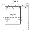
- FIG. 3 is a block diagram depicting one embodiment of an alignment of frame buffer 175 with respect to the defined physical memory pages of an image canvas 174 . While FIG. 3 depicts frame buffer 175 , the 2D image canvas 174 may comprise a plurality of 2D data arrays as described.
- Memory pages 310 , 312 , 314 , 316 , 318 , 320 , 322 , and 324 are the first few in a contiguous set of memory pages (i.e., contiguous regions of physical memory) allocated to image canvas 174 , commencing at address location 210 .
- Page boundary 330 indicates the boundary of page 310 , typically a 4 kilobyte page boundary exemplified by various generic computer architectures.
- Frame buffer 175 starts midway through memory page 316 , offset from the boundary between pages 314 and 316 by distance 340 . Unless frame buffers are page-aligned, distance 340 is a required buffer offset parameter in defining the first location of frame buffer 175 .
- FIG. 3 also depicts selected details of frame buffer slice 220 .
- Slice 220 is delineated into rectangular sub-sections of pixel areas, designated as sub-sections 222 1 - 222 N .
- the base address for slice 220 is assigned the address of pixel 308 , which is the pixel at location [0,0] in sub-section 222 1 .
- Each sub-section 222 1 - 222 N comprises a width corresponding to dimension 304 and a height corresponding to dimension 306 ; in some embodiments, each sub-section comprises a block of pixels, e.g., 8 ⁇ 8 pixels, 64 ⁇ 64 pixels, and the like. Sub-sections may comprise different widths.
- the last sub-section 222 N of slice 222 may comprise fewer or more pixel columns than other sub-sections in the slice 222 if the slice width is not equally divisible.
- slices are specified with increased height (i.e., an increased number of rows) to relax scheduling or synchronization timing.
- Yet another embodiment supports variable mask granularity whilst utilizing unchanged DMAC address processing logic by adjusting the sub-section width to support an alternative pixel packing arrangement. For example, if the sub-section width is widened to support packed 24-bit pixel data rather than unpacked 32-bit pixel data, descriptor mask granularity may be adjusted from 32 ⁇ 32-bit pixels to 128 ⁇ 24-bit pixels using the same DMAC.
- a smaller unit-column, or sub-section is selected to achieve finer resolution of sub-sections.
- the dimensions of sub-sections 222 1 - 222 N are scaled dynamically, for example responsive to image type attributes or system-level latency requirements.
- Sub-sections need not be rectangular; for example, non-rectangular sub-sections may be utilized in instances where transfer descriptors are associated with non-rectangular image content-related objects, such as icons, buttons or other non-rectangular shapes.
- FIG. 4 is a block diagram of descriptor list 164 in accordance with one or more embodiments of the present invention.
- the descriptor list 164 comprises descriptors 410 1 - 410 N located in a contiguous memory region, typically in a single memory page such that DMA access is restricted to meet security requirements.
- each sequential descriptor 410 1 - 410 N is statically associated with a corresponding sequential slice (i.e., section) of a frame buffer (ref. exemplary slice 220 of FIG. 2 ) following frame buffer memory allocation.
- descriptor list 164 comprises a non-contiguous linked list of descriptors distributed over the same or different memory pages.
- each descriptor comprises an address pointer indicating the location in memory 120 ( FIG. 1 ) of the next descriptor in the list 164 .
- Transfer scheduler 162 in FIG. 1 adds descriptors to the descriptor list 164 in any order, so that sections associated with any frame buffer can be scheduled in any desired order for processing by DMAC 140 ( FIG. 1 ).
- FIG. 5 is a block diagram of a descriptor 410 in accordance with one or more embodiments of the present invention.
- Descriptor 410 generally comprises addressing and control information utilized by DMAC 140 (ref. FIG. 1 ) for the transfer of image data located in 2D sub-sections of 2D sections designated by the stride mask of the corresponding descriptor.
- address and control information comprises source address information 510 , target parameters 520 , DMA control information 530 , stride mask 166 n , and page address information 550 .
- the descriptor 410 further comprises an address field used to point to the next descriptor in the list 164 .
- source address information 510 comprises the base address of the section, for example the address of pixel 308 in FIG. 3 , and the length of rows in the section (ref. width 240 in FIG. 2 ); alternatively, the section row length is fixed and need not be explicitly provided.
- the section base address is dynamic.
- each descriptor is associated with a window on a display, and as the window moves across the display, the slice base address is modified accordingly.
- the source address information 510 comprises a single start address for the section, and the address translation from virtual to physical address is performed by the IOMMU unit in the processor and chipset 110 .
- source address information 510 further comprises a page offset parameter (ref. offset 340 in FIG. 3 ). If the frame buffer does not match the image canvas dimensions, source address information 510 further comprises a buffer address pitch defining unused memory locations between consecutive rows (ref. address pitch 242 of frame buffer 175 in FIG. 2 ).
- Target parameters 520 generally comprise information fields containing embedded parameters or instructions (or pointers to such parameters or instructions) intended for transfer to peripheral system 150 in FIG. 1 . Such embedded parameters or instructions are transferred in conjunction with the frame buffer updates (i.e., the updated image data) and stored in allocated data structures of the target memory 152 of the peripheral system 150 . Such data structures provide peripheral system 150 with subsequent processing actions, for example by specifying attributes of the image data (e.g., display device identification information in a multi-monitor configuration or image attributes) utilized during subsequent processing steps (e.g., a specified image encoding method). Target parameters 520 may also comprise temporally-specified frame and section identification parameters.
- attributes of the image data e.g., display device identification information in a multi-monitor configuration or image attributes
- DMA control information 530 generally comprises one or more DMA control fields, including descriptor size information and various flags and/or preferences, such as ‘enable’ or ‘disable’ interrupts (e.g., “Interrupt on Completion”, ‘Interrupt at 1 ⁇ 2 complete’, ‘Last slice in frame’ to aid pre-fetching of descriptors), DMA transfer timing requirements, a ‘DMA Halt’ command, or the like.
- the descriptor size is a variable parameter that enables the DMAC 140 to locate the next descriptor in memory 120 , accounting for increased page count associated with partial buffers (i.e., embodiments in which page address information 550 includes a start address associated with a partial buffer).
- DMA control information 530 comprises a “REPEAT’ flag to indicate to DMAC 140 ( FIG. 1 ) to ignore the stride mask of the current descriptor (i.e., stride mask 166 n ) and, instead, utilize the stride mask associated with the previous descriptor.
- REPEAT flag saves the transfer scheduler from updating an entire stride mask for each descriptor in the presence of repeated update patterns across consecutive image sections.
- DMA control information 530 may further comprise skip-forward directives that allow the DMAC 140 to read the first few memory spaces of the current descriptor ( 410 n ) and then move directly to the next descriptor ( 410 n+1 ).
- Such skip-forward directives prevent wasted memory bandwidth related to reading the stride mask 166 n and page address information 550 , often comprising the bulk of a descriptor's size. Inclusion of such directives increases execution efficiency of linear descriptors (ref. FIG. 4 ) compared to linked list descriptors, as the DMAC 140 traverses a linear list more efficiently than the transfer scheduler 162 can link descriptors given the currently available hypervisor and processor chipset/support circuit technologies.
- DMA control information 530 may further comprise an IGNORE field that nullifies the descriptor 410 , used, for example, to direct the DMAC 140 to skip over the descriptors of a disconnected display device without a need to re-initialize the descriptor list 164 .
- DMA control information 530 comprises a descriptor ownership bit used as a semaphore to track whether the descriptor is owned by the transfer scheduler 162 or the DMAC 140 .
- the transfer scheduler 162 sets the ownership bit when the descriptor 410 is available for execution, and the DMAC 140 clears the ownership bit on completion.
- head and tail pointers are used to determine descriptor ownership. An embodiment of a linked list structure utilizing head and tail pointers is described further below with respect to FIG. 6 .
- Stride mask 166 n indicates which sub-sections of the frame buffer section associated with the descriptor 410 should be fetched by DMAC 140 ( FIG. 1 ) for transfer to target memory 152 ( FIG. 1 ).
- stride mask 166 n comprises an array of logic bits, one logic bit corresponding to each sub-section of the frame buffer (e.g., one bit in the array corresponding with each sub-section 222 1 - 222 N of FIG. 3 ).
- a logic ‘1’ for a bit corresponding to a sub-section indicates that the image data within the sub-section should be transferred by the DMAC 140 , while a logic ‘0’ indicates the sub-section should be skipped.
- DMAC 140 utilizes stride mask 166 n to gain processing efficiency.
- the mask information determines if DMA operations should be split or merged to ensure that efficient DMA accesses are performed.
- DMAC 140 looks ahead into descriptor list 164 using the mask as an indicator to queue multiple DMA requests.
- the physical address for each consecutive page boundary associated with a section is listed in a corresponding field of page address information 550 .
- a frame buffer has an address pitch (ref. pitch 242 for buffer 175 in FIG. 2 ) larger than a memory page (e.g., >4 kilobytes)
- complete memory pages within unused memory need not be explicitly identified in page address information 550 .
- an alternative address pitch specified in conjunction with removing page addresses associated with unused memory from page address information 550 , serves to compact the length of the descriptor list 164 .
- such an alternative address pitch may be expressed as [1 kB+(original address pitch) modulo (1 kB)], A descriptor 410 with such an alternative expression of address pitch maintains compatibility with any sized image canvas.
- FIG. 6 is a block diagram illustrating one embodiment of the descriptor list 164 , showing managed ownership between transfer scheduler 162 and DMAC 140 .
- Descriptor list 164 comprises descriptors 410 1 - 410 N , commencing at base address 602 in memory 120 ( FIG. 1 ) and ending at address 610 .
- Head pointer 620 and tail pointer 630 are memory mapped registers, visible to both transfer scheduler 162 and DMAC 140 , used to set descriptor ownership (i.e., which descriptors are owned by DMAC 140 and which are owned by the transfer scheduler 162 at any given time).
- partial descriptor list 650 is owned by DMAC 140
- partial descriptor lists 660 1 and 660 2 are owned by transfer scheduler 162 .
- transfer scheduler 162 allocates memory for descriptor list 164 between addresses 602 and 610 .
- Head pointer 620 and tail pointer 630 are initialized to base address 602 , and DMAC 140 activated. No DMA transfers occur while the head and tail pointers are at the same address.
- stride masks are updated (in response to an updated frame buffer)
- the one or more descriptors comprising the updated stride masks are written to the processing queue by the transfer scheduler 162 in FIG. 1 ; such descriptors contain address information (ref. source address information 510 and page address information 550 in FIG. 5 ) pointing to the updated frame buffer sections.
- the transfer scheduler 162 updates tail pointer 630 to the end of the added descriptors (ref.
- descriptor 410 N ⁇ 2 of FIG. 6 to indicate the descriptors that are available for DMA execution.
- DMAC 140 responds to the updated tail pointer 630 by reading descriptor 410 1 and advancing head pointer 620 to the end of descriptor 410 1 once descriptor 410 1 has been processed, followed by performing analogous operations on descriptor 410 2 , as depicted in FIG. 6 . Consequently, tail pointer 630 advances as descriptors become available for processing by DMAC 140 , and head pointer 620 advances once the available descriptors have been processed.
- FIG. 7 is a block diagram of a memory 700 comprising a virtualized software environment in accordance with one or more embodiments of the present invention.
- Memory 700 comprises a virtualized software environment in which both update manager and DMAC have access to stride masks in shared memory.
- Memory 700 depicts an alternative embodiment of memory 120 in FIG. 1 .
- Memory 700 comprises VMs 710 1 and 710 2 under management of hypervisor 730 .
- VM 710 is an operating system domain as described for VM 170 in FIG. 1 , comprising update manager 712 1 and image canvas 774 with frame buffers 775 and 776 .
- An embodiment of image canvas 774 is substantially similar to canvas 174 in FIG. 1 .
- Shared memory 720 1 stores mask set 722 1 , accessible to both VM 710 1 and the DMAC (ref. DMAC 140 in FIG. 1 ).
- Mask set 722 1 under management of update manager 712 1 , comprises stride masks (ref mask 166 1 - 166 N in FIG. 1 ) for both frame buffers 775 and 776 .
- Each stride mask indicates locations of updated image sub-sections across a section of a frame buffer (i.e., sub-sections containing updated image data).
- VM 710 2 comprises update manager 712 2 and canvas 778 with frame buffer 779 .
- Shared memory 720 2 stores a mask set 722 2 associated with frame buffer 779 , accessible to VM 710 2 and the DMAC.
- Each stride mask of the mask set 722 2 indicates locations of updated sub-sections across a section of frame buffer 779 .
- update manager 712 communicates mask identification details and attributes to transfer scheduler 732 during mask configuration.
- mask identification details include a pointer to the base address of each mask in the set (for example as a Guest Physical Address (GPA)), frame buffer address information (for example in the form of one or more GPA addresses), frame buffer structure information (such as frame buffer section width, height and bytes per pixel), and other information, such as parameters similar to target parameters 520 depicted in FIG. 5 .
- hypervisor 730 allocates memory for mask set 722 and passes addressing information to update manager 712 .
- Update manager 712 1 detects updates made by operating system or application software to image canvas 774 , and records detected sub-section updates in the corresponding mask of mask set 722 1 .
- Update manager 712 2 executes in a comparable manner.
- update manager 712 provides an indication to transfer scheduler 732 when one or masks from set 722 become available for processing so that image data within updated regions of the corresponding frame buffer can be transferred.
- Mask sets 722 1 and 722 2 may be maintained by their respective update managers at different privilege levels to the descriptors themselves comprising physical address information configured by transfer scheduler 732 .
- Such an architecture enables transfer scheduler 732 to program DMA accessibility while update managers 712 1 and 712 2 are enabled to set mask bits without direct DMA programming privileges. This eliminates a need to copy mask data from shared memory 720 to the privilege level of descriptor list 734 .
- image canvas 774 and/or image canvas 778 are located in shared memory 720 accessible to hypervisor 130 , or video memory associated with a GPU of processor and chipset 110 in FIG. 1 .
- FIG. 8 is an illustration of process 800 for transferring updated image data from sub-sections of frame buffers within a first memory to a second memory in accordance with one or more embodiments of the present invention.
- the second memory is a target memory of a peripheral system, such as peripheral system 150 .
- an image data transfer operation typically comprises copying the image data from the first memory to the second memory, leaving the image data in the first memory unchanged, in some embodiments the image data may be modified between being read from the first memory location and being written to the second memory location.
- Step 804 generally comprises initialization of hardware and memory structures such as processor and chipset 110 , memory 120 , DMAC 140 and peripheral system 150 , all shown in FIG. 1 .
- Hypervisor 160 , VMs 170 , operating systems, update managers 172 and a transfer scheduler 162 are instantiated, and related data structures such as image canvases 174 and 178 , frame buffers 175 , 176 , and 179 , and peripheral system target memory 152 are allocated and/or initialized by the operating system and other software processes.
- the operating system requests a 2D image canvas and frame buffer memory from the virtualization environment which are locked to prevent page swapping following initialization.
- Process 800 proceeds to step 810 (“Initialize Descriptors and Masks”).
- the update manager tasked with managing the bitmap mask and monitoring changes to the image data, initializes the bitmap mask.
- all bits of the mask bitmap (ref bitmap 177 ) are set during initialization to indicate a need to transfer the entire frame buffer following initialization or display configuration change.
- descriptor list 164 ( FIG. 1 ) describing all the virtualized frame buffers of the system is initialized by configuration software in the hypervisor domain.
- Each descriptor is specified in terms of buffer address, buffer offset, number of rows, row length, address pitch and a list of physical page addresses that point to each of the physical memory pages associated with the particular frame buffer.
- each descriptor (ref.
- FIG. 5 is associated with a section of 2D memory, each section further delineated into an array of 2D sub-sections (ref. sub-section 222 in FIG. 2 ).
- the descriptor list is re-initialized with updated buffer descriptions and physical address information.
- the stride masks are set to indicate the image update status.
- Process 800 proceeds to step 820 (“Update mask”).
- the stride mask associated with each descriptor is set based on the transfer requirement of the related sub-sections of the corresponding frame buffer, for example as detected by an update manager 172 in FIG. 1 .
- sub-sections deemed as updated since a previous transfer operation (ref. step 830 ) are flagged for transfer.
- each update manager sets mask values in a bitmap data structure corresponding to the descriptor stride mask.
- the transfer scheduler in the hypervisor domain then scans the bitmap for update indicia, copies the relevant row of the bitmap mask into the corresponding descriptor stride mask and schedules the descriptor for processing by a DMAC.
- the descriptor may be scheduled for processing, for example, by writing it to an output queue (and setting a tail pointer as depicted in FIG. 6 ), adding it to a linked list or setting a descriptor flag to be polled by the DMAC, thereby enabling out of order descriptor processing.
- descriptors are aggregated according to physical frame buffer accessibility attributes or ordered according to processing resource availability or ordered in a manner suited to the peripheral system (e.g., real-time attributes of the image data).
- Process 800 proceeds to step 830 (“Transfer Image Data”) in which scheduled descriptors are processed by a DMAC.
- the DMAC determines a physical page address offset and selects one or more page addresses from the list of physical page addresses in the page address information field (ref. Page Address Information 550 in FIG. 5 ) for each scheduled descriptor.
- the DMAC aggregates physical page addresses to enable burst transfer methods supported by the underlying processor expansion bus.
- the DMAC processes the scheduled list by accessing the 2D sub-section(s) referenced by descriptor stride masks and transferring the 2D sub-sections to corresponding target memory of the peripheral system.
- additional target parameters such as image attributes or display device ID information stored in the descriptor
- image rendering in the VM associated with scheduled descriptors may be paused until processing of the current scheduled list and frame buffer transfer operations are complete.
- the DMAC comprises multiple DMA engines
- a portion of the descriptor list assigned to a selection of virtualized frame buffers is scheduled for processing, typically with rendering suspended, while the update managers associated with other virtualized frame buffers concurrently execute in conjunction with the transfer scheduler to update other non-scheduled portions of the descriptor list.
- Step 830 may further comprise error handling methods that ensure image data transfer continues from valid frame buffers in the presence of other purged or corrupted frame buffers, which may, for example, become invalid during DMAC transfer operations.
- One approach comprises ignoring errors received from the hypervisor 160 or bus 114 in FIG. 1 (e.g., received Transaction Layer Protocol (TLP) errors) until an operational frame buffer is encountered.
- TLP Transaction Layer Protocol
- Process 800 proceeds to step 840 (“Indicate Transfer Status”).
- the DMAC provides an indication of the transfer completion status to the transfer scheduler.
- the DMAC may provide such an indication, for example, by performing at least one of advancing a tail pointer, clearing a software flag related to descriptor ownership, initiating an interrupt signal if a scheduled list has been processed or clearing an individual stride mask bit in conjunction with the processing of a sub-section.
- a transfer completion signal is delayed based on processing status information (e.g., image processing status) provided by the peripheral system.
- the transfer scheduler provides the update manager with an indication of transfer status so that the mask bitmap (ref mask bitmap 177 in FIG. 1 ) can be cleared in conjunction with resumed rendering to related sections.
- Process 800 proceeds to step 850 (“Complete?”), where it is determined if process 800 should continue transferring frame buffer updates. If additional transfer is required, process 800 returns to step 820 . If the display resolution or system configuration has changed (e.g., display connection change) such that redefinition of descriptors is required, process 800 returns to step 810 . If transfer is concluded, for example at the end of a computing session, process 800 ends at step 860 .
Abstract
Description
Claims (16)
Priority Applications (2)
| Application Number | Priority Date | Filing Date | Title |
|---|---|---|---|
| US12/586,498 US8073990B1 (en) | 2008-09-23 | 2009-09-23 | System and method for transferring updates from virtual frame buffers |
| US13/523,407 US9582272B1 (en) | 2009-01-26 | 2012-06-14 | Method and system for remote computing session management |
Applications Claiming Priority (2)
| Application Number | Priority Date | Filing Date | Title |
|---|---|---|---|
| US9952108P | 2008-09-23 | 2008-09-23 | |
| US12/586,498 US8073990B1 (en) | 2008-09-23 | 2009-09-23 | System and method for transferring updates from virtual frame buffers |
Publications (1)
| Publication Number | Publication Date |
|---|---|
| US8073990B1 true US8073990B1 (en) | 2011-12-06 |
Family
ID=45034511
Family Applications (1)
| Application Number | Title | Priority Date | Filing Date |
|---|---|---|---|
| US12/586,498 Expired - Fee Related US8073990B1 (en) | 2008-09-23 | 2009-09-23 | System and method for transferring updates from virtual frame buffers |
Country Status (1)
| Country | Link |
|---|---|
| US (1) | US8073990B1 (en) |
Cited By (27)
| Publication number | Priority date | Publication date | Assignee | Title |
|---|---|---|---|---|
| US20110126198A1 (en) * | 2009-11-25 | 2011-05-26 | Framehawk, LLC | Methods for Interfacing with a Virtualized Computing Service over a Network using a Lightweight Client |
| US20110235722A1 (en) * | 2010-03-26 | 2011-09-29 | Novatek Microelectronics Corp. | Computer system architecture |
| US20120110150A1 (en) * | 2010-10-29 | 2012-05-03 | Nokia Corporation | Method and apparatus for upgrading components of a cluster |
| US20120324358A1 (en) * | 2011-06-16 | 2012-12-20 | Vmware, Inc. | Delivery of a user interface using hypertext transfer protocol |
| GB2496960A (en) * | 2011-11-21 | 2013-05-29 | Ibm | Caching method for a virtual machine. |
| US20130326351A1 (en) * | 2012-05-31 | 2013-12-05 | Zhiwei Ying | Video Post-Processing on Platforms without an Interface to Handle the Video Post-Processing Request from a Video Player |
| US20140208442A1 (en) * | 2011-06-13 | 2014-07-24 | Lynuxworks, Inc. | Systems and Methods of Secure Domain Isolation Involving Separation Kernel Features |
| US20140205085A1 (en) * | 2011-12-30 | 2014-07-24 | Scott Janus | Preventing pattern recognition in electronic code book encryption |
| US20150127762A1 (en) * | 2013-11-05 | 2015-05-07 | Oracle International Corporation | System and method for supporting optimized buffer utilization for packet processing in a networking device |
| US9195488B2 (en) | 2011-11-21 | 2015-11-24 | International Business Machines Corporation | Image deployment in a cloud environment |
| US9489327B2 (en) | 2013-11-05 | 2016-11-08 | Oracle International Corporation | System and method for supporting an efficient packet processing model in a network environment |
| US9544232B2 (en) | 2011-02-16 | 2017-01-10 | Oracle International Corporation | System and method for supporting virtualized switch classification tables |
| US9549045B2 (en) | 2011-08-29 | 2017-01-17 | Vmware, Inc. | Sharing remote sessions of a user interface and/or graphics of a computer |
| US9607151B2 (en) | 2012-06-26 | 2017-03-28 | Lynx Software Technologies, Inc. | Systems and methods involving features of hardware virtualization such as separation kernel hypervisors, hypervisors, hypervisor guest context, hypervisor context, rootkit detection/prevention, and/or other features |
| US9940174B2 (en) | 2014-05-15 | 2018-04-10 | Lynx Software Technologies, Inc. | Systems and methods involving features of hardware virtualization, hypervisor, APIs of interest, and/or other features |
| US20180150407A1 (en) * | 2016-11-28 | 2018-05-31 | Oracle International Corporation | Row identification number generation in database direct memory access engine |
| US10051008B2 (en) | 2014-05-15 | 2018-08-14 | Lynx Software Technologies, Inc. | Systems and methods involving aspects of hardware virtualization such as hypervisor, detection and interception of code or instruction execution including API calls, and/or other features |
| US10095538B2 (en) | 2014-05-15 | 2018-10-09 | Lynx Software Technologies, Inc. | Systems and methods involving features of hardware virtualization, hypervisor, pages of interest, and/or other features |
| US20180293090A1 (en) * | 2017-04-11 | 2018-10-11 | Electronics And Telecommunications Research Institute | Virtual desktop server for supporting high-quality graphics processing and method for processing high-quality graphics using the same |
| US10169271B1 (en) * | 2014-10-28 | 2019-01-01 | Xilinx, Inc. | Direct memory access descriptor |
| USRE47659E1 (en) * | 2010-09-22 | 2019-10-22 | Toshiba Memory Corporation | Memory system having high data transfer efficiency and host controller |
| US10579571B2 (en) * | 2014-04-01 | 2020-03-03 | Sony Interactive Entertainment Inc. | Processing system and multiprocessing system |
| US10824715B2 (en) | 2014-07-01 | 2020-11-03 | Lynx Software Technologies, Inc. | Systems and methods involving aspects of hardware virtualization such as separation kernel hypervisors, hypervisors, hypervisor guest context, hypervisor context, anti-fingerprinting, and/or other features |
| US20200348922A1 (en) * | 2019-05-03 | 2020-11-05 | EMC IP Holding Company LLC | System and method for state management |
| US11093276B2 (en) * | 2018-01-24 | 2021-08-17 | Alibaba Group Holding Limited | System and method for batch accessing |
| US11410264B2 (en) * | 2019-09-27 | 2022-08-09 | Intel Corporation | Switchable image source in a hybrid graphics systems |
| US11782745B2 (en) | 2014-07-01 | 2023-10-10 | Lynx Software Technologies, Inc. | Systems and methods involving aspects of hardware virtualization such as separation kernel hypervisors, hypervisors, hypervisor guest context, hypervisor context, anti-fingerprinting and/or other features |
Citations (44)
| Publication number | Priority date | Publication date | Assignee | Title |
|---|---|---|---|---|
| US5018076A (en) | 1988-09-16 | 1991-05-21 | Chips And Technologies, Inc. | Method and circuitry for dual panel displays |
| US5526017A (en) | 1990-12-11 | 1996-06-11 | International Business Machines Corporation | Analog image signal processor for a multimedia system |
| US5880741A (en) | 1994-05-13 | 1999-03-09 | Seiko Epson Corporation | Method and apparatus for transferring video data using mask data |
| US6012101A (en) | 1998-01-16 | 2000-01-04 | Int Labs, Inc. | Computer network having commonly located computing systems |
| US6038616A (en) | 1997-12-15 | 2000-03-14 | Int Labs, Inc. | Computer system with remotely located interface where signals are encoded at the computer system, transferred through a 4-wire cable, and decoded at the interface |
| US6046751A (en) | 1997-02-10 | 2000-04-04 | Ssd Company Limited | Color graphics processor |
| US6119146A (en) | 1998-05-04 | 2000-09-12 | Int Labs, Inc. | Computer network having multiple remotely located human interfaces sharing a common computing system |
| US6154793A (en) | 1997-04-30 | 2000-11-28 | Zilog, Inc. | DMA with dynamically assigned channels, flexible block boundary notification and recording, type code checking and updating, commands, and status reporting |
| US20010000539A1 (en) | 1997-12-15 | 2001-04-26 | Andrew Heller | Computer on a card with a remote human interface |
| US6252979B1 (en) | 1995-06-07 | 2001-06-26 | Tripath Imaging, Inc. | Interactive method and apparatus for sorting biological specimens |
| US20010011965A1 (en) | 1998-10-30 | 2001-08-09 | Barry G. Wilks | Method and apparatus for supporting multiple displays |
| US6292853B1 (en) | 1997-10-02 | 2001-09-18 | Kabushiki Kaisha Toshiba | DMA controller adapted for transferring data in two-dimensional mapped address space |
| US6333750B1 (en) | 1997-03-12 | 2001-12-25 | Cybex Computer Products Corporation | Multi-sourced video distribution hub |
| US20020099919A1 (en) * | 2000-12-19 | 2002-07-25 | Thales | Method of memory management |
| US20020149617A1 (en) | 2001-03-30 | 2002-10-17 | Becker David F. | Remote collaboration technology design and methodology |
| US6483515B1 (en) | 1999-04-09 | 2002-11-19 | Sun Microsystems, Inc. | Method and apparatus for displaying data patterns in information systems |
| US20020180725A1 (en) | 2001-04-23 | 2002-12-05 | Quantum3D, Inc. | System and method for synchronization of video display outputs from multiple PC graphics subsystems |
| US6570890B1 (en) | 1998-06-10 | 2003-05-27 | Merlot Communications | Method for the transmission and control of audio, video, and computer data over a single network fabric using ethernet packets |
| US20030098820A1 (en) | 1999-06-14 | 2003-05-29 | Mitsubishi Denki Kabushiki Kaisha | Image signal generating apparatus, image signal transmission apparatus, image signal generating method, image signal transmission method, image display unit, control method for an image display unit, and image display system |
| US20030193486A1 (en) | 2002-04-15 | 2003-10-16 | Estrop Stephen J. | Methods and apparatuses for facilitating processing of interlaced video images for progressive video displays |
| US20030208340A1 (en) | 1998-04-23 | 2003-11-06 | Micron Technology, Inc. | Remote semiconductor microscopy |
| US20030212811A1 (en) | 2002-04-08 | 2003-11-13 | Clearcube Technology, Inc. | Selectively updating a display in a multi-diplay system |
| US6662246B2 (en) | 1998-11-16 | 2003-12-09 | Viewahead Technology, Inc. | Two-dimensional memory access in image processing systems |
| US6664969B1 (en) | 1999-11-12 | 2003-12-16 | Hewlett-Packard Development Company, L.P. | Operating system independent method and apparatus for graphical remote access |
| US20040001622A1 (en) | 2002-06-27 | 2004-01-01 | Roylance Eugene A. | Method and system for image processing including mixed resolution, multi-channel color compression, transmission and decompression |
| US20040015597A1 (en) | 2002-07-18 | 2004-01-22 | Thornton Barry W. | Distributing video data in a system comprising co-located computers and remote human interfaces |
| US6806885B1 (en) | 1999-03-01 | 2004-10-19 | Micron Technology, Inc. | Remote monitor controller |
| US20040212730A1 (en) | 1998-11-09 | 2004-10-28 | Broadcom Corporation | Video and graphics system with video scaling |
| US20040222941A1 (en) | 2002-12-30 | 2004-11-11 | Wong Mark Yuk-Lun | Multi-display architecture using single video controller |
| US20050060421A1 (en) | 2003-07-16 | 2005-03-17 | Musunuri Chowdhary V. | System and method for providing immersive visualization at low bandwidth rates |
| US20050204015A1 (en) | 2004-03-11 | 2005-09-15 | Steinhart Jonathan E. | Method and apparatus for generation and transmission of computer graphics data |
| US6963946B1 (en) | 2003-10-01 | 2005-11-08 | Advanced Micro Devices, Inc. | Descriptor management systems and methods for transferring data between a host and a peripheral |
| US20050257239A1 (en) | 2004-05-17 | 2005-11-17 | Microsoft Corporation | Reverse presentation of digital media streams |
| US20060080514A1 (en) * | 2004-10-08 | 2006-04-13 | International Business Machines Corporation | Managing shared memory |
| US7095386B2 (en) | 2001-06-07 | 2006-08-22 | Nvidia Corporation | Graphics system including a plurality of heads |
| US20060233201A1 (en) | 2002-12-18 | 2006-10-19 | Hartmut Wiesenthal | Adaptive encoding of digital multimedia information |
| US7133362B2 (en) | 2001-11-14 | 2006-11-07 | Microsoft Corporation | Intelligent buffering process for network conference video |
| US7136394B2 (en) | 2001-03-12 | 2006-11-14 | Polycom, Inc. | Low-delay video encoding method for concealing the effects of packet loss in multi-channel packet switched networks |
| US20060282855A1 (en) | 2005-05-05 | 2006-12-14 | Digital Display Innovations, Llc | Multiple remote display system |
| US20070097130A1 (en) | 2005-11-01 | 2007-05-03 | Digital Display Innovations, Llc | Multi-user terminal services accelerator |
| US20070124474A1 (en) | 2005-11-30 | 2007-05-31 | Digital Display Innovations, Llc | Multi-user display proxy server |
| US7317685B1 (en) | 2001-11-26 | 2008-01-08 | Polycom, Inc. | System and method for dynamic bandwidth allocation for videoconferencing in lossy packet switched networks |
| US7350053B1 (en) * | 2005-01-11 | 2008-03-25 | Sun Microsystems, Inc. | Software accessible fast VA to PA translation |
| US7988251B2 (en) * | 2006-07-03 | 2011-08-02 | Telecom Italia, S.P.A. | Method and system for high speed multi-pass inkjet printing |
-
2009
- 2009-09-23 US US12/586,498 patent/US8073990B1/en not_active Expired - Fee Related
Patent Citations (48)
| Publication number | Priority date | Publication date | Assignee | Title |
|---|---|---|---|---|
| US5018076A (en) | 1988-09-16 | 1991-05-21 | Chips And Technologies, Inc. | Method and circuitry for dual panel displays |
| US5526017A (en) | 1990-12-11 | 1996-06-11 | International Business Machines Corporation | Analog image signal processor for a multimedia system |
| US5880741A (en) | 1994-05-13 | 1999-03-09 | Seiko Epson Corporation | Method and apparatus for transferring video data using mask data |
| US6252979B1 (en) | 1995-06-07 | 2001-06-26 | Tripath Imaging, Inc. | Interactive method and apparatus for sorting biological specimens |
| US6046751A (en) | 1997-02-10 | 2000-04-04 | Ssd Company Limited | Color graphics processor |
| US6333750B1 (en) | 1997-03-12 | 2001-12-25 | Cybex Computer Products Corporation | Multi-sourced video distribution hub |
| US6154793A (en) | 1997-04-30 | 2000-11-28 | Zilog, Inc. | DMA with dynamically assigned channels, flexible block boundary notification and recording, type code checking and updating, commands, and status reporting |
| US6292853B1 (en) | 1997-10-02 | 2001-09-18 | Kabushiki Kaisha Toshiba | DMA controller adapted for transferring data in two-dimensional mapped address space |
| US7043748B2 (en) | 1997-12-15 | 2006-05-09 | Clearcube Technology, Inc. | Computer network comprising computing systems with remotely located human interfaces |
| US6038616A (en) | 1997-12-15 | 2000-03-14 | Int Labs, Inc. | Computer system with remotely located interface where signals are encoded at the computer system, transferred through a 4-wire cable, and decoded at the interface |
| US6385666B1 (en) | 1997-12-15 | 2002-05-07 | Clearcube Technology, Inc. | Computer system having remotely located I/O devices where signals are encoded at the computer system through two encoders and decoded at I/O devices through two decoders |
| US20020059639A1 (en) | 1997-12-15 | 2002-05-16 | Int Labs, Inc. | Computer network comprising computing systems with remotely located human interfaces |
| US20010000539A1 (en) | 1997-12-15 | 2001-04-26 | Andrew Heller | Computer on a card with a remote human interface |
| US6012101A (en) | 1998-01-16 | 2000-01-04 | Int Labs, Inc. | Computer network having commonly located computing systems |
| US20030208340A1 (en) | 1998-04-23 | 2003-11-06 | Micron Technology, Inc. | Remote semiconductor microscopy |
| US6119146A (en) | 1998-05-04 | 2000-09-12 | Int Labs, Inc. | Computer network having multiple remotely located human interfaces sharing a common computing system |
| US6570890B1 (en) | 1998-06-10 | 2003-05-27 | Merlot Communications | Method for the transmission and control of audio, video, and computer data over a single network fabric using ethernet packets |
| US20010011965A1 (en) | 1998-10-30 | 2001-08-09 | Barry G. Wilks | Method and apparatus for supporting multiple displays |
| US20040212730A1 (en) | 1998-11-09 | 2004-10-28 | Broadcom Corporation | Video and graphics system with video scaling |
| US6662246B2 (en) | 1998-11-16 | 2003-12-09 | Viewahead Technology, Inc. | Two-dimensional memory access in image processing systems |
| US6806885B1 (en) | 1999-03-01 | 2004-10-19 | Micron Technology, Inc. | Remote monitor controller |
| US6483515B1 (en) | 1999-04-09 | 2002-11-19 | Sun Microsystems, Inc. | Method and apparatus for displaying data patterns in information systems |
| US20030098820A1 (en) | 1999-06-14 | 2003-05-29 | Mitsubishi Denki Kabushiki Kaisha | Image signal generating apparatus, image signal transmission apparatus, image signal generating method, image signal transmission method, image display unit, control method for an image display unit, and image display system |
| US6664969B1 (en) | 1999-11-12 | 2003-12-16 | Hewlett-Packard Development Company, L.P. | Operating system independent method and apparatus for graphical remote access |
| US20020099919A1 (en) * | 2000-12-19 | 2002-07-25 | Thales | Method of memory management |
| US7136394B2 (en) | 2001-03-12 | 2006-11-14 | Polycom, Inc. | Low-delay video encoding method for concealing the effects of packet loss in multi-channel packet switched networks |
| US20020149617A1 (en) | 2001-03-30 | 2002-10-17 | Becker David F. | Remote collaboration technology design and methodology |
| US20020180725A1 (en) | 2001-04-23 | 2002-12-05 | Quantum3D, Inc. | System and method for synchronization of video display outputs from multiple PC graphics subsystems |
| US7095386B2 (en) | 2001-06-07 | 2006-08-22 | Nvidia Corporation | Graphics system including a plurality of heads |
| US7133362B2 (en) | 2001-11-14 | 2006-11-07 | Microsoft Corporation | Intelligent buffering process for network conference video |
| US7317685B1 (en) | 2001-11-26 | 2008-01-08 | Polycom, Inc. | System and method for dynamic bandwidth allocation for videoconferencing in lossy packet switched networks |
| US7161557B2 (en) | 2002-04-08 | 2007-01-09 | Clearcube Technology, Inc. | Selectively updating a display in a multi-display system |
| US20030212811A1 (en) | 2002-04-08 | 2003-11-13 | Clearcube Technology, Inc. | Selectively updating a display in a multi-diplay system |
| US20030193486A1 (en) | 2002-04-15 | 2003-10-16 | Estrop Stephen J. | Methods and apparatuses for facilitating processing of interlaced video images for progressive video displays |
| US20040001622A1 (en) | 2002-06-27 | 2004-01-01 | Roylance Eugene A. | Method and system for image processing including mixed resolution, multi-channel color compression, transmission and decompression |
| US20040015597A1 (en) | 2002-07-18 | 2004-01-22 | Thornton Barry W. | Distributing video data in a system comprising co-located computers and remote human interfaces |
| US20060233201A1 (en) | 2002-12-18 | 2006-10-19 | Hartmut Wiesenthal | Adaptive encoding of digital multimedia information |
| US20040222941A1 (en) | 2002-12-30 | 2004-11-11 | Wong Mark Yuk-Lun | Multi-display architecture using single video controller |
| US20050060421A1 (en) | 2003-07-16 | 2005-03-17 | Musunuri Chowdhary V. | System and method for providing immersive visualization at low bandwidth rates |
| US6963946B1 (en) | 2003-10-01 | 2005-11-08 | Advanced Micro Devices, Inc. | Descriptor management systems and methods for transferring data between a host and a peripheral |
| US20050204015A1 (en) | 2004-03-11 | 2005-09-15 | Steinhart Jonathan E. | Method and apparatus for generation and transmission of computer graphics data |
| US20050257239A1 (en) | 2004-05-17 | 2005-11-17 | Microsoft Corporation | Reverse presentation of digital media streams |
| US20060080514A1 (en) * | 2004-10-08 | 2006-04-13 | International Business Machines Corporation | Managing shared memory |
| US7350053B1 (en) * | 2005-01-11 | 2008-03-25 | Sun Microsystems, Inc. | Software accessible fast VA to PA translation |
| US20060282855A1 (en) | 2005-05-05 | 2006-12-14 | Digital Display Innovations, Llc | Multiple remote display system |
| US20070097130A1 (en) | 2005-11-01 | 2007-05-03 | Digital Display Innovations, Llc | Multi-user terminal services accelerator |
| US20070124474A1 (en) | 2005-11-30 | 2007-05-31 | Digital Display Innovations, Llc | Multi-user display proxy server |
| US7988251B2 (en) * | 2006-07-03 | 2011-08-02 | Telecom Italia, S.P.A. | Method and system for high speed multi-pass inkjet printing |
Non-Patent Citations (25)
| Title |
|---|
| "Advances in Memory Management for Windows", Microsoft Corporation, Oct. 12, 2007. |
| "OpenGL Vizserver(TM) 3.1 Application-Transparent Remote Interactive Visualization and Collaboration", Silicon Graphics Inc. 15 Pages, 2003. |
| "OpenGL Vizserver™ 3.1 Application-Transparent Remote Interactive Visualization and Collaboration", Silicon Graphics Inc. 15 Pages, 2003. |
| "VMware Workload Management with AppSense Performance Manager", Whitepaper, AppSense Ltd, 3200 Daresbury Park, Daresbury, Warrington, WA4 4BU, United Kingdom, No publication date listed, 12 Pages. |
| "Zero Client Technology: History, Use and Critical Comparison", Applica Inc. Web Article (http://www.applica.com/zeroCtech.shtml), pp. 1-5, Copyright 1997-2005. |
| A. Heirich and L. Moll. "Scalable Distributed Visualization Using Off-the-Shelf Components", IEEE Parallel Visualization and Graphics Symposium-1999, San Francisco, California, pp. 55-60, Oct. 1999. |
| ABTS, Dennis et al., "The Cray Black Widow: A Highly Scalable Vector Multiprocessor," Proceedings of the 2007 ACM/IEEE Conference on Supercomputing (Reno, Nevada, Nov. 10-16, 2007), SC '07, ACM, New York, NY, pp. 1-12. |
| Applica Presenter Product Datasheet, entitled "One PC Can Display and Manage Up to 16 Remote Monitors, Over CAT5 With (Optional) Touch Screen Support", SmartAVI, Inc, 3111 Winona Ave, Suite 101 Burbank, CA 91504, pp. 1-4, no date. |
| Appsense Performance Manager Datasheet v1.1, entitled "Dynamically Manage System Performance, Availability and Capacity", 2 Pages, 2005. |
| Brian Paul, Sean Ahern, E. Wes Bethel, Eric Brugger, Rich Cook, Jamison Daniel, Ken Lewis, Jens Owen, Dale Southard, "Chromium Renderserver: Scalable and Open Remote Rendering Infrastructure," IEEE Transactions on Visualization and Computer Graphics, vol. 14, No. 3, 14 Pages, May/Jun. 2008. |
| Dale Beermann, Greg Humphreys, "Visual Computing in the Future: Computer Graphics as a Remote Service", University of Virginia, Computer Science Department, University of Virginia Technical Report CS-2003-16, 25 Pages, Jun. 1, 2003. |
| Dowty, M. and Sugerman, J., "GPU Virtualization on VMware's Hosted I/O Architecture", SIGOPS Oper. Syst. Rev. 43, Jul. 3, 2009, 73-82. N.Y., USA, pp. 1-8. |
| Final Office Action mailed Apr. 1, 2010 for U.S. Appl. No. 11/278,128 entitled "Methods and Apparatus for Enabling Multiple Remote Displays", David V. Hobbs, filed Mar. 30, 2006, pp. 1-36. |
| Greg Humphreys, Matthew Eldridge, Ian Buck, Gordon Stoll, Matthew Everett, and Pat Hanrahan. "WireGL: A Scalable Graphics System for Clusters", Computer Graphics (SIGGRAPH 2001), 12 Pages, 2001. |
| Han Chen, Yuqun Chen, Adam Finkelstein, Thomas Funkhouser, Kai Li, Zhiyan Liu, Rudrajit Samanta, and Grant Wallace. "Data Distribution Strategies for High-Resolution Displays", Computers & Graphics. vol. 25 No. 5 :811-818, Oct. 2001, 14 Pages. |
| Jonathan Chien-Liang Liu, David H.C. Du, Simon S.Y. Shim, Jenwei Hsieh, MengJou Lin, "Design and Evaluation of a Generic Software Architecture for On-Demand Video Servers," IEEE Transactions on Knowledge and Data Engineering, vol. 11, No. 3, 20 Pages, May/Jun. 1999. |
| Lagar-Cavilla, H. A., Tolia, N., Satyanarayanan, M., and de Lara, E. 2007. "VMM-Independent Graphics Acceleration", In Proceedings of the 3rd International Conference on Virtual Execution Environments (San Diego, California, USA, Jun. 13-15, 2007). VEE '07. ACM, New York, NY, 11 Pages. |
| Office Action mailed Aug. 5, 2009, for U.S. Appl. No. 11/278,128 entitled "Methods and Apparatus for Enabling Multiple Remote Displays", David V. Hobbs, filed Mar. 30, 2006, 32 Pages. |
| Rajvikram Singh, Byungil Jeong, Luc Renambot, Andrew Johnson, Jason Leigh, "TeraVision: a Distributed, Scalable, High Resolution Graphics Streaming System", Proceedings of Cluster 2004, San Diego, CA, 10 pages, Sep. 2004. |
| Roger Zimmermann and Dwipal A. Desai, "Ethernet Interface for Head-Mounted Displays", USC technical Report USC-CS-TR05-846, Integrated Media Systems Center, University of Southern California, 12 Pages, Mar. 2005. |
| Tristan Richardson, Quentin Stafford-Fraser,Kenneth R. Wood and Andy Hopper, "Virtual Network Computing", Reprint from IEEE Internet Computing vol. 2, No. 1, 7 Pages, Jan./Feb. 1998. |
| U.S. Appl. No. 11/904,879 entitled "Method and Apparatus for Scheduling a Resource of A Virtual Machine", David Victor Hobbs, filed Sep. 28, 2007, pp. 1-41. |
| U.S. Appl. No. 12/460,384 entitled "Method and System for Image Sequence Transfer Scheduling", David Victor Hobbs, filed Jul. 17, 2009, pp. 1-62. |
| U.S. Appl. No. 12/460,384, filed Jul. 17, 2009, entitled "Method and System for Image Sequence Transfer Scheduling." |
| William Blanke, Chandrajit Bajaj, Donald Fussell, and Xiaoyu Zhang, "The Metabuffer: A Scalable Multiresolution Multidisplay 3-D Graphics System Using Commodity Rendering Engines", TR200-16, The University of Texas at Austin, 7 Pages, Feb. 2000. |
Cited By (53)
| Publication number | Priority date | Publication date | Assignee | Title |
|---|---|---|---|---|
| US20110126198A1 (en) * | 2009-11-25 | 2011-05-26 | Framehawk, LLC | Methods for Interfacing with a Virtualized Computing Service over a Network using a Lightweight Client |
| US9183025B2 (en) | 2009-11-25 | 2015-11-10 | Citrix Systems, Inc. | Systems and algorithm for interfacing with a virtualized computing service over a network using a lightweight client |
| US8676949B2 (en) * | 2009-11-25 | 2014-03-18 | Citrix Systems, Inc. | Methods for interfacing with a virtualized computing service over a network using a lightweight client |
| US10908975B2 (en) * | 2010-03-26 | 2021-02-02 | Novatek Microelectronics Corp. | Computer system architecture |
| US20110235722A1 (en) * | 2010-03-26 | 2011-09-29 | Novatek Microelectronics Corp. | Computer system architecture |
| USRE47659E1 (en) * | 2010-09-22 | 2019-10-22 | Toshiba Memory Corporation | Memory system having high data transfer efficiency and host controller |
| USRE48736E1 (en) | 2010-09-22 | 2021-09-14 | Kioxia Corporation | Memory system having high data transfer efficiency and host controller |
| USRE49875E1 (en) | 2010-09-22 | 2024-03-19 | Kioxia Corporation | Memory system having high data transfer efficiency and host controller |
| US20120110150A1 (en) * | 2010-10-29 | 2012-05-03 | Nokia Corporation | Method and apparatus for upgrading components of a cluster |
| US9032053B2 (en) * | 2010-10-29 | 2015-05-12 | Nokia Corporation | Method and apparatus for upgrading components of a cluster |
| US9544232B2 (en) | 2011-02-16 | 2017-01-10 | Oracle International Corporation | System and method for supporting virtualized switch classification tables |
| US10061606B2 (en) | 2011-06-13 | 2018-08-28 | Lynx Software Technologies, Inc. | Systems and methods of secure domain isolation involving separation kernel features |
| US20140208442A1 (en) * | 2011-06-13 | 2014-07-24 | Lynuxworks, Inc. | Systems and Methods of Secure Domain Isolation Involving Separation Kernel Features |
| US9575824B2 (en) | 2011-06-13 | 2017-02-21 | Lynx Software Technologies, Inc. | Systems and methods of secure domain isolation involving separation kernel features |
| US9129123B2 (en) * | 2011-06-13 | 2015-09-08 | Lynx Software Technologies, Inc. | Systems and methods of secure domain isolation involving separation kernel features |
| US9600350B2 (en) * | 2011-06-16 | 2017-03-21 | Vmware, Inc. | Delivery of a user interface using hypertext transfer protocol |
| US20120324358A1 (en) * | 2011-06-16 | 2012-12-20 | Vmware, Inc. | Delivery of a user interface using hypertext transfer protocol |
| US9549045B2 (en) | 2011-08-29 | 2017-01-17 | Vmware, Inc. | Sharing remote sessions of a user interface and/or graphics of a computer |
| US9195488B2 (en) | 2011-11-21 | 2015-11-24 | International Business Machines Corporation | Image deployment in a cloud environment |
| US9195489B2 (en) | 2011-11-21 | 2015-11-24 | International Business Machines Corporation | Image deployment in a cloud environment |
| GB2496960A (en) * | 2011-11-21 | 2013-05-29 | Ibm | Caching method for a virtual machine. |
| US9081788B2 (en) | 2011-11-21 | 2015-07-14 | International Business Machines Corporation | Customizable file-type aware cache mechanism |
| US9081787B2 (en) | 2011-11-21 | 2015-07-14 | International Business Machines Corporation | Customizable file-type aware cache mechanism |
| GB2496960B (en) * | 2011-11-21 | 2014-02-05 | Ibm | Caching method and system for executing the caching method for operating a computer server system comprising at least one host |
| US10110374B2 (en) * | 2011-12-30 | 2018-10-23 | Intel Corporation | Preventing pattern recognition in electronic code book encryption |
| US20140205085A1 (en) * | 2011-12-30 | 2014-07-24 | Scott Janus | Preventing pattern recognition in electronic code book encryption |
| US20170070342A1 (en) * | 2011-12-30 | 2017-03-09 | Intel Corporation | Preventing Pattern Recognition in Electronic Code Book Encryption |
| US9531916B2 (en) * | 2011-12-30 | 2016-12-27 | Intel Corporation | Preventing pattern recognition in electronic code book encryption |
| US20130326351A1 (en) * | 2012-05-31 | 2013-12-05 | Zhiwei Ying | Video Post-Processing on Platforms without an Interface to Handle the Video Post-Processing Request from a Video Player |
| US9607151B2 (en) | 2012-06-26 | 2017-03-28 | Lynx Software Technologies, Inc. | Systems and methods involving features of hardware virtualization such as separation kernel hypervisors, hypervisors, hypervisor guest context, hypervisor context, rootkit detection/prevention, and/or other features |
| US10671727B2 (en) | 2012-06-26 | 2020-06-02 | Lynx Software Technologies, Inc. | Systems and methods involving features of securely handling attempts to perform boot modifications(s) via a separation kernel hypervisor |
| US11861005B2 (en) | 2012-06-26 | 2024-01-02 | Lynx Software Technologies, Inc. | Systems and methods involving features of hardware virtualization such as separation kernel hypervisors, hypervisors, hypervisor guest context, hypervisor context, rootkit detection/prevention, and/or other features |
| US9858241B2 (en) * | 2013-11-05 | 2018-01-02 | Oracle International Corporation | System and method for supporting optimized buffer utilization for packet processing in a networking device |
| US20150127762A1 (en) * | 2013-11-05 | 2015-05-07 | Oracle International Corporation | System and method for supporting optimized buffer utilization for packet processing in a networking device |
| US9489327B2 (en) | 2013-11-05 | 2016-11-08 | Oracle International Corporation | System and method for supporting an efficient packet processing model in a network environment |
| US10579571B2 (en) * | 2014-04-01 | 2020-03-03 | Sony Interactive Entertainment Inc. | Processing system and multiprocessing system |
| US9940174B2 (en) | 2014-05-15 | 2018-04-10 | Lynx Software Technologies, Inc. | Systems and methods involving features of hardware virtualization, hypervisor, APIs of interest, and/or other features |
| US10095538B2 (en) | 2014-05-15 | 2018-10-09 | Lynx Software Technologies, Inc. | Systems and methods involving features of hardware virtualization, hypervisor, pages of interest, and/or other features |
| US10051008B2 (en) | 2014-05-15 | 2018-08-14 | Lynx Software Technologies, Inc. | Systems and methods involving aspects of hardware virtualization such as hypervisor, detection and interception of code or instruction execution including API calls, and/or other features |
| US10789105B2 (en) | 2014-05-15 | 2020-09-29 | Lynx Software Technologies, Inc. | Systems and methods involving features of hardware virtualization, hypervisor, APIs of interest, and/or other features |
| US11782766B2 (en) | 2014-05-15 | 2023-10-10 | Lynx Software Technologies, Inc. | Systems and methods involving features of hardware virtualization, hypervisor, APIs of interest, and/or other features |
| US10824715B2 (en) | 2014-07-01 | 2020-11-03 | Lynx Software Technologies, Inc. | Systems and methods involving aspects of hardware virtualization such as separation kernel hypervisors, hypervisors, hypervisor guest context, hypervisor context, anti-fingerprinting, and/or other features |
| US11782745B2 (en) | 2014-07-01 | 2023-10-10 | Lynx Software Technologies, Inc. | Systems and methods involving aspects of hardware virtualization such as separation kernel hypervisors, hypervisors, hypervisor guest context, hypervisor context, anti-fingerprinting and/or other features |
| US10169271B1 (en) * | 2014-10-28 | 2019-01-01 | Xilinx, Inc. | Direct memory access descriptor |
| US20180150407A1 (en) * | 2016-11-28 | 2018-05-31 | Oracle International Corporation | Row identification number generation in database direct memory access engine |
| US10176114B2 (en) * | 2016-11-28 | 2019-01-08 | Oracle International Corporation | Row identification number generation in database direct memory access engine |
| US20180293090A1 (en) * | 2017-04-11 | 2018-10-11 | Electronics And Telecommunications Research Institute | Virtual desktop server for supporting high-quality graphics processing and method for processing high-quality graphics using the same |
| US10656956B2 (en) * | 2017-04-11 | 2020-05-19 | Electronics And Telecommunications Research Institute | Virtual desktop server for supporting high-quality graphics processing and method for processing high-quality graphics using the same |
| US11093276B2 (en) * | 2018-01-24 | 2021-08-17 | Alibaba Group Holding Limited | System and method for batch accessing |
| US11733994B2 (en) * | 2019-05-03 | 2023-08-22 | EMC IP Holding Company LLC | System and method for state management |
| US20200348922A1 (en) * | 2019-05-03 | 2020-11-05 | EMC IP Holding Company LLC | System and method for state management |
| US11410264B2 (en) * | 2019-09-27 | 2022-08-09 | Intel Corporation | Switchable image source in a hybrid graphics systems |
| US11935151B2 (en) | 2019-09-27 | 2024-03-19 | Intel Corporation | Switchable image source in a hybrid graphics systems |
Similar Documents
| Publication | Publication Date | Title |
|---|---|---|
| US8073990B1 (en) | System and method for transferring updates from virtual frame buffers | |
| US11768781B2 (en) | Apparatus and method for memory management in a graphics processing environment | |
| US11475623B2 (en) | Apparatus and method for efficient graphics virtualization | |
| US10304421B2 (en) | Apparatus and method for remote display and content protection in a virtualized graphics processing environment | |
| US8239938B2 (en) | Centralized device virtualization layer for heterogeneous processing units | |
| US7262776B1 (en) | Incremental updating of animated displays using copy-on-write semantics | |
| US7015915B1 (en) | Programming multiple chips from a command buffer | |
| US8065687B2 (en) | Bypass virtualization | |
| US10891237B2 (en) | Apparatus and method for mediate pass through and shared memory page merge | |
| US10983821B2 (en) | Apparatus and method for a hybrid layer of address mapping for a virtualized input/output (I/O) implementation | |
| US8780122B2 (en) | Techniques for transferring graphics data from system memory to a discrete GPU | |
| US9099051B2 (en) | GPU display abstraction and emulation in a virtualization system | |
| US11341212B2 (en) | Apparatus and method for protecting content in virtualized and graphics environments | |
| US11436696B2 (en) | Apparatus and method for provisioning virtualized multi-tile graphics processing hardware | |
| US11854114B2 (en) | Apparatus and method for seamless container migration for graphics processors and associated devices | |
| US8698814B1 (en) | Programmable compute engine screen mapping | |
| Marchesin | Linux Graphics Drivers: an Introduction |
Legal Events
| Date | Code | Title | Description |
|---|---|---|---|
| AS | Assignment |
Owner name: TERADICI CORPORATION, CANADA Free format text: ASSIGNMENT OF ASSIGNORS INTEREST;ASSIGNORS:BARON, CHARLES PETER;DOUCETTE, DANIEL JEAN DONAT;HELTER, PAUL ANDREW;AND OTHERS;SIGNING DATES FROM 20090921 TO 20090922;REEL/FRAME:023327/0401 |
|
| ZAAA | Notice of allowance and fees due |
Free format text: ORIGINAL CODE: NOA |
|
| ZAAB | Notice of allowance mailed |
Free format text: ORIGINAL CODE: MN/=. |
|
| STCF | Information on status: patent grant |
Free format text: PATENTED CASE |
|
| AS | Assignment |
Owner name: WF FUND IV LIMITED PARTNERSHIP, CANADA Free format text: SECURITY AGREEMENT;ASSIGNOR:TERADICI CORPORATION;REEL/FRAME:029800/0593 Effective date: 20130204 |
|
| FPAY | Fee payment |
Year of fee payment: 4 |
|
| AS | Assignment |
Owner name: BEEDIE CAPITAL PARTNERS FUND I LIMITED PARTNERSHIP Free format text: SECURITY INTEREST;ASSIGNOR:TERADICI CORPORATION;REEL/FRAME:037988/0364 Effective date: 20160219 |
|
| AS | Assignment |
Owner name: COMERICA BANK, MICHIGAN Free format text: SECURITY INTEREST;ASSIGNOR:TERADICI CORPORATION;REEL/FRAME:048454/0895 Effective date: 20190222 |
|
| AS | Assignment |
Owner name: TERADICI CORPORATION, CANADA Free format text: RELEASE BY SECURED PARTY;ASSIGNOR:BEEDIE CAPITAL PARTNERS FUND I LIMITED PARTNERSHIP;REEL/FRAME:048473/0846 Effective date: 20190226 |
|
| AS | Assignment |
Owner name: TERADICI CORPORATION, CANADA Free format text: RELEASE BY SECURED PARTY;ASSIGNOR:WF FUND IV LIMITED PARTNERSHIP;REEL/FRAME:048499/0800 Effective date: 20190228 |
|
| MAFP | Maintenance fee payment |
Free format text: PAYMENT OF MAINTENANCE FEE, 8TH YEAR, LARGE ENTITY (ORIGINAL EVENT CODE: M1552); ENTITY STATUS OF PATENT OWNER: LARGE ENTITY Year of fee payment: 8 |
|
| FEPP | Fee payment procedure |
Free format text: MAINTENANCE FEE REMINDER MAILED (ORIGINAL EVENT CODE: REM.); ENTITY STATUS OF PATENT OWNER: LARGE ENTITY |
|
| LAPS | Lapse for failure to pay maintenance fees |
Free format text: PATENT EXPIRED FOR FAILURE TO PAY MAINTENANCE FEES (ORIGINAL EVENT CODE: EXP.); ENTITY STATUS OF PATENT OWNER: LARGE ENTITY |
|
| STCH | Information on status: patent discontinuation |
Free format text: PATENT EXPIRED DUE TO NONPAYMENT OF MAINTENANCE FEES UNDER 37 CFR 1.362 |
|
| FP | Lapsed due to failure to pay maintenance fee |
Effective date: 20231206 |