US8073823B2 - Database management program - Google Patents
Database management program Download PDFInfo
- Publication number
- US8073823B2 US8073823B2 US11/922,936 US92293605A US8073823B2 US 8073823 B2 US8073823 B2 US 8073823B2 US 92293605 A US92293605 A US 92293605A US 8073823 B2 US8073823 B2 US 8073823B2
- Authority
- US
- United States
- Prior art keywords
- duplicated
- segments
- empty space
- sequential
- rows
- Prior art date
- Legal status (The legal status is an assumption and is not a legal conclusion. Google has not performed a legal analysis and makes no representation as to the accuracy of the status listed.)
- Expired - Fee Related, expires
Links
- 238000007726 management method Methods 0.000 claims abstract description 47
- 238000000034 method Methods 0.000 description 81
- 238000010586 diagram Methods 0.000 description 29
- 238000003780 insertion Methods 0.000 description 17
- 230000037431 insertion Effects 0.000 description 17
- 238000012545 processing Methods 0.000 description 17
- 238000012217 deletion Methods 0.000 description 4
- 230000037430 deletion Effects 0.000 description 4
- 230000008707 rearrangement Effects 0.000 description 4
- 230000001174 ascending effect Effects 0.000 description 2
- 230000006870 function Effects 0.000 description 2
- 238000012423 maintenance Methods 0.000 description 2
- 230000003287 optical effect Effects 0.000 description 2
- 238000007796 conventional method Methods 0.000 description 1
- 238000013461 design Methods 0.000 description 1
- 239000012464 large buffer Substances 0.000 description 1
- 230000007774 longterm Effects 0.000 description 1
- 230000000737 periodic effect Effects 0.000 description 1
Images


Classifications
-
- G—PHYSICS
- G06—COMPUTING; CALCULATING OR COUNTING
- G06F—ELECTRIC DIGITAL DATA PROCESSING
- G06F16/00—Information retrieval; Database structures therefor; File system structures therefor
- G06F16/20—Information retrieval; Database structures therefor; File system structures therefor of structured data, e.g. relational data
- G06F16/28—Databases characterised by their database models, e.g. relational or object models
- G06F16/284—Relational databases
Definitions
- the present invention relates to database management systems (DBMSs) in which the data space is segmentalized, and, more particularly, to database management programs of DBMSs implemented for embedded devices.
- DBMSs database management systems
- list fetch is a function that is used frequently in many applications in which such devices are employed, such as car navigation systems, music players, and HDD recorders.
- a dedicated file system is typically used in which emphasis is placed on real-time processing performance of list fetch operations that use an I/O device that performs seek processing extremely slowly (for example, an I/O device that performs seek processing on CD/DVD storage format) and are implemented so that data to be list-displayed is positioned in sequential space on the disk.
- a dedicated file system is designed for a device that performs no update operation, and in a case where update is performed using a device capable of update operation (for example, an HDD), the data is rearranged at each update operation.
- Non-Patent Document 1 As a function to allocate data in sequential space, there is a clustered table that guarantees that data is sorted physically with respect to a specified clustered key column of the table. For example, this shown in Non-Patent Document 1, which is cited herein below.
- FIG. 4 an example of a conventional embodiment of the clustered table in a DBMS in which storage space management is composed of pages and segments is shown in FIG. 4 and is explained hereinafter.
- a page ( 5002 ) is a physical unit representing a minimum unit of data I/O to a storage space ( 5001 ), and each of segments ( 5003 , 5004 ) is a physical unit representing a minimum unit for allocation of space in a table and an index. Each segment is composed of a plurality of the pages.
- the relation between the clustered table and the storage space is shown in FIG. 5 .
- the clustered table ( 6001 ) is a clustered table in which a sequential number column ( 6002 ) is set as a clustered key column and segments on storage space ( 6007 ) are allocated.
- Rows ( 6003 , 6004 , 6005 ) of the clustered table ( 6001 ) are stored in a segment ( 6014 ) on the storage space ( 6007 ), and another segment ( 6015 ) is also allocated to the clustered key column.
- the sequential number column is set as the clustered key column
- data is sorted physically with respect to the sequential number column.
- empty space ( 6012 , 6013 ) is secured for future insert operations.
- insert processing ( 7001 ) for performing the insert operation first, the size of a row to be inserted and the size of empty spaces of the storage space are compared to make a judgment ( 7002 ) of whether the insertion can be performed. Here, if the insertion cannot be performed, an error judgment is made ( 7012 ), and the insert processing ends ( 7009 ).
- a segment including a largest row among rows having a clustered key that is equal or smaller to that of the largest row is searched for in the storage space ( 7003 ), and a judgment ( 7004 ) of whether there is empty space to insert the row for insertion in the segment is made. If such empty space exists, a procedure A ( 7013 ) is carried out. In procedure A, first, a lock of an index related to a corresponding table is obtained ( 7005 ), and then, the row is inserted into the empty space in the segment ( 7006 ), the index is updated ( 7007 ), the lock of the index is released ( 7008 ), and the insert processing ends ( 7009 ).
- FIG. 7 An operation example in a case where a row having a clustered key of 12 is inserted according to procedure A ( 7013 ) is shown in FIG. 7 .
- the row ( 8006 ) having the clustered key of 12 is inserted into the empty space in the same segment.
- procedure B a procedure B ( 7014 ) is carried out.
- procedure B first, a lock of the index related to the corresponding table is obtained ( 7010 ), and then, the row is inserted into a new segment ( 7011 ), the lock of the index is released ( 7007 ), and the insert processing ends ( 7009 ).
- An operation example for a case where a row having a clustered key of 12 is inserted according to procedure B ( 8014 ) is shown in FIG. 8 .
- intersection data is handled in units of map information.
- the intersection data is divided into sections ( 10001 ) each having a unique identifier and individually managed.
- real-time processing performance of list fetch operations of the intersection data is of primary importance. Such a list fetch is performed in a route search in the present example in the following two patterns:
- a pattern in which all data is arranged in sequential space in a case of a file system dedicated for car navigation is used as the pattern of 1, and in which it is impossible to arrange all data including the pattern 2 in the sequential space. Therefore, also in a DBMS specialized for an embedded application, it is sufficient to guarantee that the pattern 1 is arranged in the sequential space.
- a search condition uses an equality condition of a section number and that a plurality of intersections having the same section number exist in search target data.
- list fetch operations also appear frequently in applications other than the car navigation application discussed above. For example, list fetch operations such as “list of music titles by an identical artist” and “list of music titles contained in an identical album” in music player applications, as well as “list of programs of a specified month and day” and “list of programs of a specified channel” in HDD recorder applications, frequently appear.
- Non-Patent Document 1 [Product Manual] Scalable Database Server HiRDB Version 7 System Introduction and Design Guide (For UNIX®) 3000-6-272, 12.9 Specification of Clustered Key”, pp. 342-343.
- an object of exemplary embodiments of the present invention is to provide a database management program in which the time required for a search specifying a condition of column A is not lengthened and a time-consuming rearrangement of all rows is not required, even if insert, deletion, and update operations of the rows are repeated and, moreover, even in a case where a row having a duplicated value of column A is arranged in the sequential space at an initial state to speed up the search specifying the condition of column A.
- a database management program when no empty sequential space is found in a space where the rows having a duplicate value in column A are arranged on storage when performing insertion, deletion, and update operations, only a set of rows having the duplicate value in column A are arranged in the sequential space using an algorithm having a characteristic of including a procedure to search for a sequential empty space that has larger capacity than that used for all the rows having the duplicate value of column A, and a procedure to move all the rows having the duplicate value of column A to the empty space in a case where such an empty space is found by the search.
- the present invention when managing a single set or a plurality of sets of rows having duplicate values in column A using a relational database, in a case where a row having a duplicate value of column A is arranged in a sequential space at an initial state to speed up the search having the condition of column A, even if insertion, deletion, and update operations of a plurality of rows are repeated, the time required for the search specifying the condition of column A is not lengthened, and a time-consuming rearrangement of all rows is not required.
- FIG. 1 is a block diagram showing a structure of a database management system according to a first embodiment of the present invention
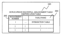
- FIG. 2 is a data configuration diagram showing a duplicated ID sequential arrangement table identification table according to the first embodiment of the present invention
- FIG. 3 is a configuration diagram showing a duplicated ID sequential arrangement table ID management table according to the first embodiment of the present invention
- FIG. 4 is an explanatory diagram showing a storage space management method composed of a page and a segment in an embodiment of a clustered table of a conventional system
- FIG. 5 is an explanatory diagram showing relation between the clustered table and storage space in the embodiment of the clustered table of the conventional system
- FIG. 6 is an explanatory diagram showing a flow chart of insert operation to the clustered table in the embodiment of the clustered table of the conventional system
- FIG. 7 is an explanatory diagram showing an example of a procedure A in the flow chart of the insert operation to the clustered table in the embodiment of the clustered table of the conventional system;
- FIG. 8 is an explanatory diagram showing an example of a procedure B in the flow chart of the insert operation to the clustered table in the embodiment of the clustered table of the conventional system;
- FIG. 9 is an explanatory diagram showing a characteristic of list fetch of the conventional system taking car navigation application as an example
- FIG. 10 is an explanatory diagram showing an example of a structure of a table including a duplicated key according to the first embodiment of the present invention.
- FIG. 11 is an explanatory diagram showing a structure of a duplicated ID sequential arrangement table on storage space according to the first embodiment of the present invention.
- FIG. 12 is an explanatory diagram showing an example of a schematic view of the structure of the duplicated ID sequential arrangement table on the storage space according to the first embodiment of the present invention
- FIG. 13 is an explanatory diagram showing a flow chart of insert operation to the duplicated ID sequential arrangement table according to the first embodiment of the present invention
- FIG. 14 is an explanatory diagram showing an example of a procedure A in the flow chart of the insert operation to the duplicated ID sequential arrangement table according to the first embodiment of the present invention
- FIG. 15 is an explanatory diagram showing an example of a procedure B in the flow chart of the insert operation to the duplicated ID sequential arrangement table according to the first embodiment of the present invention
- FIG. 16 is an explanatory diagram showing an example of a procedure C in the flow chart of the insert operation to the duplicated ID sequential arrangement table according to the first embodiment of the present invention
- FIG. 17 is an explanatory diagram showing an example of a procedure D in the flow chart of the insert operation to the duplicated ID sequential arrangement table according to the first embodiment of the present invention.
- FIG. 18 is an explanatory diagram showing an example of a procedure E in the flow chart of the insert operation to the duplicated ID sequential arrangement table according to the first embodiment of the present invention
- FIG. 19 is an explanatory diagram showing an example of a structure of a table including first-order and second-order duplicated keys according to a second embodiment of the present invention and a structure thereof on storage space;
- FIG. 20 is an explanatory diagram showing a flow chart of insert operation to a duplicated ID sequential arrangement table according to the second embodiment of the present invention.
- FIG. 21 is an explanatory diagram showing an example of a procedure A in the flow chart of the insert operation to the duplicated ID sequential arrangement table according to the second embodiment of the present invention.
- FIG. 22 is an explanatory diagram showing an example of a procedure B in the flow chart of the insert operation to the duplicated ID sequential arrangement table according to the second embodiment of the present invention.
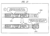
- FIG. 23 is an explanatory diagram showing an example of a procedure C in the flow chart of the insert operation to the duplicated ID sequential arrangement table according to the second embodiment of the present invention.
- FIG. 24 is an explanatory diagram showing an example of a procedure D in the flow chart of the insert operation to the duplicated ID sequential arrangement table according to the second embodiment of the present invention.
- FIG. 25 is an explanatory diagram showing a method of structuring a duplicated ID sequential arrangement table identification table, a duplicated ID sequential arrangement table ID management table and a duplicated ID sequential arrangement table parent-child relation management table suitable for operation of the duplicated ID sequential arrangement table according to the second embodiment of the present invention
- FIG. 26 is a diagram showing an example of a Z-order storage method according to a third embodiment of the present invention.
- FIG. 27 is a diagram showing an example of the Z-order storage method according to the third embodiment of the present invention.
- FIG. 28 is an explanatory diagram showing an example of a structure of a table including a duplicated key based on the Z-order storage method according to the third embodiment of the present invention and a structure thereof on storage space;
- FIG. 29 is an explanatory diagram showing a method of structuring a duplicated ID sequential arrangement table identification table, a duplicated ID sequential arrangement table ID management table and a duplicated ID sequential arrangement table parent-child relation management table suitable for operation of a duplicated ID sequential arrangement table according to the third embodiment of the present invention.
- FIGS. 1 to 3 and FIGS. 10 to 18 A first embodiment of the present invention is described with reference to FIGS. 1 to 3 and FIGS. 10 to 18 .
- FIG. 1 shows an overall structure of a database management system according to the first embodiment of the present invention.
- a database server ( 1001 ) and an update client ( 1012 ) and a search client ( 1014 ) are connected via a network ( 1016 ).
- the database server ( 1001 ) executes a database management program ( 1002 ) and includes a storage device ( 1008 ).
- the database management program ( 1002 ) includes a data update module ( 1003 ) and a data search module ( 1004 ), and further includes a duplicated ID sequential arrangement table identification table ( 1005 ), a duplicated ID sequential arrangement table ID management table ( 1006 ) and a duplicated ID sequential arrangement table parent-child relation management table ( 1007 ).
- the storage device ( 1008 ) stores storage space ( 1009 ), and in the storage space ( 1009 ), a duplicated ID sequential arrangement table ( 1010 ) and an index ( 1011 ) are stored.
- the data update module ( 1003 ) and the data search module ( 1004 ) refer to the duplicated ID sequential arrangement table identification table ( 1005 ), the duplicated ID sequential arrangement table ID management table ( 1006 ) and the duplicated ID sequential arrangement table parent-child relation management table ( 1007 ), and identify the duplicated ID sequential arrangement table ( 1010 ) and the index ( 1011 ).
- the duplicated ID sequential arrangement table parent-child relation management table ( 1007 ) mainly used in the second embodiment and the third embodiment. In the explanation of the first embodiment described hereinafter, the duplicated ID sequential arrangement table parent-child relation management table ( 1007 ) does not appear.
- the duplicated ID sequential arrangement table identification table ( 1005 ) is a table in which a table that is an object of arrangement and management is registered so that data having duplicate IDs are arranged sequentially, and is structured to include a management number column ( 2002 ) and a table name column ( 2003 ).
- a table named an intersection table is registered as the object of the arrangement and management with a management number 1.
- the duplicated ID sequential arrangement table ID management table 1006 has a table name column ( 3002 ) and a column name column ( 3003 ).
- a column name to be a standard of sequential arrangement is registered in correspondence with a table name which is the object of the arrangement and management.
- FIG. 10 shows an actual example implementation of the intersection table described above.
- the intersection table ( 11001 ) is a table storing the intersection data divided into sections from in FIG. 9 .
- a column ( 11002 ) named ID corresponds to a section identifier.
- ID management table ( 1006 ) by setting an ID column value to a key, data of the intersection table ( 11001 ) is arranged and managed.
- storing to the duplicated ID sequential arrangement table ( 1010 ) is performed so that data of rows having duplicate values in the ID column is arranged in a sequential position.
- the duplicated ID sequential arrangement table is a table having a characteristic that a set of rows ( 12002 ) having the same ID on the storage space ( 1009 ) is arranged ( 12005 ) in adjacent segments ( 12004 ). Further, in the same manner as the case of the clustered table, empty space ( 12006 ) is secured for preparation for future insert operations.
- a plurality of segments structuring a set of rows ( 12002 ) having the same ID arranged in adjacent segments is referred to herein below as a set of rows ( 13001 ) of the same ID composed of a set of segments shown in FIG. 12 .
- used space ( 12005 ) and empty space ( 12006 ) are referred to shortly as used space ( 13002 ) and empty space ( 13003 ), respectively.
- an insert processing ( 14001 ) performing the insert operation first, size of a row to be inserted and size of empty space of the storage space are compared, and a judgment ( 14002 ) of whether the insertion can be performed is made. Here, if the insertion cannot be performed, an error judgment is made ( 14021 ), and the insert processing ends ( 14010 ). If the insertion can be performed, a search ( 14003 ) is performed for a position of a set of segments including a set of rows having the same ID in the storage space. Different from the case of the clustered table described above, this search ( 14003 ) is based on an equality condition, and there may be a case in which the set of segments cannot be found. Therefore, a judgment ( 14004 ) of whether the set of segments is found is carried out.
- a judgment ( 14005 ) of whether there is empty space to insert a row in a first partial set of the set of segments is carried out. If there is empty space, procedure A ( 14022 ) is carried out. In procedure A ( 14022 ), first, a lock of the index related to a corresponding table is obtained ( 14006 ), and then, the row is inserted into the empty space of the first partial set of the set of segments ( 14007 ), the index is updated ( 14008 ), the lock of the index is released ( 14009 ) and the insert processing ends ( 14010 ).
- the row is inserted into the empty space in a set of same segments ( 15002 ).
- procedure B ( 14023 )
- a lock related to a corresponding table is obtained ( 14013 )
- an entire existing set of rows having the same ID as that of the row to be inserted is moved ( 14014 ) to a set of new segments to be secured in the empty space found in the search ( 14011 )
- the row is inserted into empty space of a set of the same segments ( 14015 )
- the index is updated ( 14008 )
- the lock of the index is released ( 14009 )
- the insert processing ends 14010 ).
- a judgment ( 14016 ) of whether there is a partial set having empty space in partial sets of the set of segments having the same ID as that of the row to be inserted is made. If such a partial set of the set of segments having empty space is found according to the judgment ( 14016 ), a procedure C ( 14024 ) is carried out.
- procedure C ( 14024 ), first, a lock related to a corresponding table is obtained ( 14013 ), the row is inserted into the partial set of the set of segments having the empty space ( 14018 ), the index is updated ( 14008 ), the lock of the index is released ( 14009 ), and the insert processing ends ( 14010 ).
- An operation example in a case where a row of ID 13 is inserted according to procedure C ( 14024 ) is shown in FIG. 16 .
- procedure D ( 14025 ) is carried out.
- procedure D ( 14025 ) first, a lock related to a corresponding table is obtained ( 14019 ), and then, the row is inserted into a new partial set of the set of segments ( 14020 ), the index is updated ( 14008 ), the lock of the index is released ( 14009 ), and the insert processing ends ( 14010 ).
- procedure E ( 14026 ) is carried out.
- procedure E ( 14026 ) first, a lock related to a corresponding table is obtained ( 14019 ), and then, the row is inserted ( 14020 ) into a new partial set of the set of segments, the index is updated ( 14008 ), the lock of the index is released ( 14009 ), and the insert processing ends ( 14010 ).
- FIG. 19 shows an example in which, among columns structuring an intersection table ( 21001 ), an ID column ( 21003 ) and a road type column ( 21002 ) are arranged ( 21005 , 21006 ) within a physical vicinity on storage space ( 21004 ).
- a plurality of columns designated to be arranged within a physical vicinity are sequentially called n-th-order key columns, and in the more dominant column, a value of n is set larger.
- all data can be fetched collectively.
- an equality condition search of a road type column ( 21002 ), which is a first-order key column since rows matching the condition are organized, data can be fetched at high speed.
- a road type column which is a first-order key column
- Such a table is one obtained by expanding a duplicated ID sequential arrangement table so as to cope with a plurality of columns.
- a method of performing insert operation to the duplicated ID sequential arrangement table expanded to a plurality of columns is described with reference to a flow chart shown in FIG. 20 .
- procedure A ( 22028 )
- the row is inserted into an empty space of a first-order set of segments ( 22011 )
- the index is updated ( 22012 )
- the lock of the index is released ( 22013 )
- the insert operation ends ( 22014 ).
- the row is inserted ( 23002 ) into the empty space of a set of the same segments.
- procedure B 22029
- procedure B ( 22029 ) since a first-order set of segments to which the row is inserted was not found in the judgment ( 22004 ), first, empty space is secured ( 22010 ) for the first-order set of segments. And then, the row is inserted ( 22011 ) into the empty space of the first-order set of segments, the index is updated ( 22012 ), the lock of the index is released ( 22013 ), and the insert operation ends ( 22014 ).
- the procedure proceeds from the judgment ( 22017 ), and the lock of the index related to the corresponding table is obtained ( 22019 ).
- a procedure C ( 22030 ) is carried out.
- empty space for the first-order set of segments is secured ( 22021 )
- the row is inserted ( 22022 ) into the empty space of the first-order set of segments
- the index is updated ( 22012 )
- the lock of the index is released ( 22013 )
- empty space for the first-order set of segments is secured in the empty space ( 25002 ), and then, the row is inserted ( 25003 ) into the empty space of the first-order set of segments.
- procedure D 22031
- procedure D ( 22031 ) since judgment that sequential empty space larger than a j-th-order set of segments higher than first-order is found in the judgment ( 22017 ) is made, the j-th-order set of segments is rearranged in a sequential space.
- sequential empty space larger than the j-th-order set of segments is secured ( 22023 ) in the empty space found in the search ( 22016 ), and then, the first-order set of segments is moved ( 22024 ) to n, which is an insertion row, in ascending order, the row is inserted ( 22025 ) into empty space of the first-order set of segments, the first-order set of segments is moved ( 22026 ) from n, which is the insertion row, or later in ascending order, the index is updated ( 22012 ), the lock of the index is released ( 22013 ), and the insert operation ends ( 22014 ).
- first-order set of segments 26001
- second-order set of segments 26002
- the second-order set of segments is rearranged ( 26004 ) collectively in sequential space.
- the duplicated ID sequential arrangement table identification table ( 27001 ) is composed of a management number ( 27002 ) column and a table name ( 27003 ) column, and is the same as the duplicated ID sequential arrangement table identification table 1005 according to the first embodiment shown in FIG. 2 .
- the duplicated ID sequential arrangement table ID management table ( 27004 ) is composed of a table name ( 27005 ) column and a column name ( 2700 . 6 ) column
- the duplicated ID sequential arrangement table parent-child relation management table is composed of a table name ( 27008 ) column, a column name ( 27009 ) column, and an order number ( 27010 ) column.
- intersection table ( 21001 ) is stored as the duplicated ID sequential arrangement table by designating the road type column ( 21002 ) in FIG. 19 as a first-order key column and the ID column ( 21003 ) as a second-order key column
- a row ( 27011 ) indicating the intersection table is included in the duplicated ID sequential arrangement table identification table ( 27001 )
- a row ( 27012 ) showing the road type column of the intersection table and a row ( 27013 ) indicating the ID column are included in the duplicated ID sequential arrangement table ID management table ( 27004 )
- a row ( 27014 ) showing that an order number of the road type column is 1 and a row ( 27015 ) showing that an order number of the ID column is 2 are included in the duplicated ID sequential arrangement table parent-child relation management table ( 27007 ).
- a Z-order storage method is an effective storage method of map data divided into sections ( 10001 ) as shown in FIG. 9 .
- An example of the Z-order storage method is shown in FIG. 26 .
- the Z-order storage method is a method allocating identification numbers of sections in a Z-shaped order, and storing data in order of the section numbers.
- identification numbers from 1 to 4 are allocated in Z-shaped ( 28005 ) order to a set of adjacent four sections ( 28001 , 28002 , 28003 , 28004 ) at left top.
- Z-order storage method in a case where an intersection list fetch is performed for the nine sections around the car marked as A ( 28006 ), intersection data of adjacent four sections marked as ‘a’ ( 28007 ) can be fetched collectively.
- the Z-order storage method can be expanded to the space of four or more adjacent sections.
- An example of second-order Z-order storage handling the adjacent 16 sections is shown in FIG. 27 .
- a set of the adjacent 16 sections is structured by allocating four sets of adjacent four sections in Z-shaped order.
- identification numbers are allocated to the four sets of adjacent four sections ( 29001 , 29002 , 29003 , 29004 ) in Z-shaped order ( 29005 ).
- sets of adjacent four sections ( 29001 , 29002 , 29003 , 29004 ) are referred to as a first-order Z-shape
- the set of adjacent 16 sections ( 29005 ) is referred to as a second-order Z-shape.
- sections from 1 ( 29006 ) to 16 ( 29007 ) can be stored so as to be fetched collectively. And, by enlarging the Z-shape in the same manner, expansion such as to obtain a third-order Z-shape composed of 64 adjacent sections or a fourth-order Z-shape composed of 256 adjacent sections can be made.
- the four sections included in the same first-order Z-shape have a characteristic that values obtained by dividing (section number-1) by four are equal.
- the value obtained by adding 1 to this quotient is defined as a first-order Z-shape identifier.
- the first-order Z-shape identifiers ( 28008 , 28009 , 28010 , 28011 , 28012 , 28013 , 28014 , 28015 , 28016 , 28017 , 28018 , 28019 , 29020 , 28021 , 28022 , 28023 ) are identifiers allocated according to the above definition.
- a value obtained by adding 1 to a quotient obtained by dividing (first-order Z-shape identifier-1) by four is referred to as a second-order Z-shape identifier.
- the numerals 1 , 2 , 3 , and 4 indicated by reference symbols 29008 to 29011 in FIG. 27 are the second-order Z-shape identifiers allocated sequentially according to the above definition.
- the Z-order storage method handled in the present embodiment can be embodied as a special example of the duplicated ID sequential arrangement table expanded to a plurality of columns shown in the second embodiment irrespective of a storage order.
- FIG. 28 shows an example in which a first-order Z-order storage method is expanded to a plurality of columns.
- a fourth adjacent four sections ( 28011 ) and a fifth adjacent four sections ( 28012 ) are arranged among the four adjacent four sections in first-order Z-shaped order shown in FIG. 26 .
- the first-order Z-shape identifiers as the second-order key columns, it can be embodied as a special example of the duplicated ID sequential arrangement table expanded to two columns.
- n-th Z-shape identifiers as n+1-th key columns, it can be embodied as a special example of a duplicated ID sequential arrangement table expanded to n+1 columns.
- a duplicated ID sequential arrangement identification table, a duplicated ID sequential arrangement ID management table and a duplicated ID sequential arrangement table parent-child relation management table used in the present embodiment are described with reference to FIG. 29 .
- information to be managed in the duplicated ID sequential arrangement table parent-child relation management table is different.
- a condition column ( 31010 ) column is provided so that it can be identified whether it follows to the Z-order storage method.
- the duplicated ID sequential arrangement table identification table ( 31001 ) is composed of a management number ( 31002 ) column and a table name ( 31003 ) column in the same manner as in the second embodiment, and the duplicated ID sequential arrangement table ID management table ( 31004 ) is structured of a table name ( 31005 ) column and a column name ( 31006 ) column in the same manner as in the second embodiment.
- a row ( 31012 ) indicating the intersection table is included in the duplicated ID sequential arrangement table identification table ( 31001 )
- a row ( 31013 ) indicating the ID column of the intersection table is included in the duplicated ID sequential arrangement table ID management table ( 31004 )
- a row ( 31014 ) showing that an order number of the ID column is 1 and the Z-order storage method is applied and a row ( 31015 ) showing that an order number of the ID column is 2 and the Z-order storage method is applied in the same manner are included in the duplicated ID sequential arrangement table parent-child relation management table ( 31007 ).
- the Z-order storage method is taken as an example, however, an N-order storage method arranging N-shaped order four vicinities in the same manner and a clock-order storage method arranging four vicinities clockwise can known easily by analogy. Also in the duplicated ID sequential arrangement table parent-child relation management table ( 31007 ) in the present embodiment, by designating the N-order storage method or the clock-order storage method in the condition column ( 31010 ), the N-order storage method or the clock-order storage method can be realized.
Abstract
Description
Claims (1)
Applications Claiming Priority (1)
| Application Number | Priority Date | Filing Date | Title |
|---|---|---|---|
| PCT/JP2005/016965 WO2007032068A1 (en) | 2005-09-14 | 2005-09-14 | Database management program |
Publications (2)
| Publication Number | Publication Date |
|---|---|
| US20080281791A1 US20080281791A1 (en) | 2008-11-13 |
| US8073823B2 true US8073823B2 (en) | 2011-12-06 |
Family
ID=37864674
Family Applications (1)
| Application Number | Title | Priority Date | Filing Date |
|---|---|---|---|
| US11/922,936 Expired - Fee Related US8073823B2 (en) | 2005-09-14 | 2005-09-14 | Database management program |
Country Status (3)
| Country | Link |
|---|---|
| US (1) | US8073823B2 (en) |
| JP (1) | JP4699469B2 (en) |
| WO (1) | WO2007032068A1 (en) |
Families Citing this family (4)
| Publication number | Priority date | Publication date | Assignee | Title |
|---|---|---|---|---|
| JP4878178B2 (en) * | 2006-02-28 | 2012-02-15 | 株式会社日立製作所 | Data processing method and apparatus, and processing program therefor |
| US8930371B1 (en) * | 2008-06-30 | 2015-01-06 | Amazon Technologies, Inc. | Systems and methods for efficiently storing index data on an electronic device |
| KR101642072B1 (en) * | 2014-05-08 | 2016-07-22 | 주식회사 알티베이스 | Method and Apparatus for Hybrid storage |
| US10884998B2 (en) * | 2018-09-14 | 2021-01-05 | International Business Machines Corporation | Method for migrating data records from a source database to a target database |
Citations (8)
| Publication number | Priority date | Publication date | Assignee | Title |
|---|---|---|---|---|
| JPH0392942A (en) | 1989-09-06 | 1991-04-18 | Hitachi Ltd | Storing method and accessing method for file |
| JPH07152615A (en) | 1993-11-29 | 1995-06-16 | Nec Corp | Data base reorganization system |
| JPH0869403A (en) | 1994-08-26 | 1996-03-12 | Fuji Xerox Co Ltd | File management device |
| JPH11110265A (en) | 1997-10-03 | 1999-04-23 | Fujitsu Ltd | Information processor |
| US6397311B1 (en) * | 1990-01-19 | 2002-05-28 | Texas Instruments Incorporated | System and method for defragmenting a file system |
| US20040006574A1 (en) * | 2002-04-26 | 2004-01-08 | Andrew Witkowski | Methods of navigating a cube that is implemented as a relational object |
| US20080059412A1 (en) * | 2006-08-31 | 2008-03-06 | Tarin Stephen A | Value-instance connectivity computer-implemented database |
| US20080059492A1 (en) * | 2006-08-31 | 2008-03-06 | Tarin Stephen A | Systems, methods, and storage structures for cached databases |
-
2005
- 2005-09-14 WO PCT/JP2005/016965 patent/WO2007032068A1/en active Application Filing
- 2005-09-14 JP JP2007535349A patent/JP4699469B2/en not_active Expired - Fee Related
- 2005-09-14 US US11/922,936 patent/US8073823B2/en not_active Expired - Fee Related
Patent Citations (8)
| Publication number | Priority date | Publication date | Assignee | Title |
|---|---|---|---|---|
| JPH0392942A (en) | 1989-09-06 | 1991-04-18 | Hitachi Ltd | Storing method and accessing method for file |
| US6397311B1 (en) * | 1990-01-19 | 2002-05-28 | Texas Instruments Incorporated | System and method for defragmenting a file system |
| JPH07152615A (en) | 1993-11-29 | 1995-06-16 | Nec Corp | Data base reorganization system |
| JPH0869403A (en) | 1994-08-26 | 1996-03-12 | Fuji Xerox Co Ltd | File management device |
| JPH11110265A (en) | 1997-10-03 | 1999-04-23 | Fujitsu Ltd | Information processor |
| US20040006574A1 (en) * | 2002-04-26 | 2004-01-08 | Andrew Witkowski | Methods of navigating a cube that is implemented as a relational object |
| US20080059412A1 (en) * | 2006-08-31 | 2008-03-06 | Tarin Stephen A | Value-instance connectivity computer-implemented database |
| US20080059492A1 (en) * | 2006-08-31 | 2008-03-06 | Tarin Stephen A | Systems, methods, and storage structures for cached databases |
Non-Patent Citations (5)
| Title |
|---|
| "Scalable Database Server", HiRDB Version 7 System Introduction and Design Guide (for UNIX®) pp. 342-343 in Japanese and 5 pages of English translation. |
| Bach, The Design of the Unix Operating System, 1986, Prentice Hall, Inc., 1st ed, 1st ed, pp. 60-88, 272-276. * |
| International Search Report for PCT/JP2005/016965 mailed Oct. 25, 2005. |
| Rusling, The Linux Kernel, Apr. 1997, http://www.science.unitn.it/, Version 0.1-10(30), http://www.science.unitn.it/~fiorella/guidelinux/tlk/tlk-html.html. * |
| Rusling, The Linux Kernel, Apr. 1997, http://www.science.unitn.it/, Version 0.1-10(30), http://www.science.unitn.it/˜fiorella/guidelinux/tlk/tlk-html.html. * |
Also Published As
| Publication number | Publication date |
|---|---|
| WO2007032068A1 (en) | 2007-03-22 |
| US20080281791A1 (en) | 2008-11-13 |
| JPWO2007032068A1 (en) | 2009-03-19 |
| JP4699469B2 (en) | 2011-06-08 |
Similar Documents
| Publication | Publication Date | Title |
|---|---|---|
| CN102129458B (en) | Method and device for storing relational database | |
| US10496621B2 (en) | Columnar storage of a database index | |
| EP2069979B1 (en) | Dynamic fragment mapping | |
| US7418544B2 (en) | Method and system for log structured relational database objects | |
| US20120303633A1 (en) | Systems and methods for querying column oriented databases | |
| US20120221523A1 (en) | Database Backup and Restore with Integrated Index Reorganization | |
| EP4035023A1 (en) | A method of performing transactional and analytical data processing using a data structure | |
| US20130013648A1 (en) | Method for database storage of a table with plural schemas | |
| KR100787079B1 (en) | Table format data presenting method, inserting method, deleting method, and updating method | |
| JPH1131096A (en) | Data storage/retrieval system | |
| CN102890678A (en) | Gray-code-based distributed data layout method and query method | |
| CN107783988A (en) | The locking method and equipment of a kind of directory tree | |
| US7363284B1 (en) | System and method for building a balanced B-tree | |
| US8682872B2 (en) | Index page split avoidance with mass insert processing | |
| US6745198B1 (en) | Parallel spatial join index | |
| US8073823B2 (en) | Database management program | |
| JPWO2020234719A5 (en) | ||
| US20200278980A1 (en) | Database processing apparatus, group map file generating method, and recording medium | |
| WO2015129109A1 (en) | Index management device | |
| CN111190903A (en) | Btree block indexing technology for disaster recovery client | |
| US8812453B2 (en) | Database archiving using clusters | |
| US10990575B2 (en) | Reorganization of databases by sectioning | |
| CN1492363A (en) | Data storage and searching method of embedded system | |
| US11899640B2 (en) | Method of building and appending data structures in a multi-host environment | |
| US20230177034A1 (en) | Method for grafting a scion onto an understock data structure in a multi-host environment |
Legal Events
| Date | Code | Title | Description |
|---|---|---|---|
| AS | Assignment |
Owner name: HITACHI, LTD., JAPAN Free format text: ASSIGNMENT OF ASSIGNORS INTEREST;ASSIGNORS:ITO, DAISUKE;TANIZAKI, MASAAKI;KIMURA, KOHJI;REEL/FRAME:020444/0388;SIGNING DATES FROM 20071226 TO 20080108 Owner name: HITACHI, LTD., JAPAN Free format text: ASSIGNMENT OF ASSIGNORS INTEREST;ASSIGNORS:ITO, DAISUKE;TANIZAKI, MASAAKI;KIMURA, KOHJI;SIGNING DATES FROM 20071226 TO 20080108;REEL/FRAME:020444/0388 |
|
| ZAAA | Notice of allowance and fees due |
Free format text: ORIGINAL CODE: NOA |
|
| ZAAB | Notice of allowance mailed |
Free format text: ORIGINAL CODE: MN/=. |
|
| STCF | Information on status: patent grant |
Free format text: PATENTED CASE |
|
| FPAY | Fee payment |
Year of fee payment: 4 |
|
| MAFP | Maintenance fee payment |
Free format text: PAYMENT OF MAINTENANCE FEE, 8TH YEAR, LARGE ENTITY (ORIGINAL EVENT CODE: M1552); ENTITY STATUS OF PATENT OWNER: LARGE ENTITY Year of fee payment: 8 |
|
| FEPP | Fee payment procedure |
Free format text: MAINTENANCE FEE REMINDER MAILED (ORIGINAL EVENT CODE: REM.); ENTITY STATUS OF PATENT OWNER: LARGE ENTITY |
|
| LAPS | Lapse for failure to pay maintenance fees |
Free format text: PATENT EXPIRED FOR FAILURE TO PAY MAINTENANCE FEES (ORIGINAL EVENT CODE: EXP.); ENTITY STATUS OF PATENT OWNER: LARGE ENTITY |
|
| STCH | Information on status: patent discontinuation |
Free format text: PATENT EXPIRED DUE TO NONPAYMENT OF MAINTENANCE FEES UNDER 37 CFR 1.362 |
|
| FP | Lapsed due to failure to pay maintenance fee |
Effective date: 20231206 |