US8073282B2 - Scaling filter for video sharpening - Google Patents
Scaling filter for video sharpening Download PDFInfo
- Publication number
- US8073282B2 US8073282B2 US11/781,797 US78179707A US8073282B2 US 8073282 B2 US8073282 B2 US 8073282B2 US 78179707 A US78179707 A US 78179707A US 8073282 B2 US8073282 B2 US 8073282B2
- Authority
- US
- United States
- Prior art keywords
- sharpening
- scaling
- filter coefficients
- scaling filter
- new
- Prior art date
- Legal status (The legal status is an assumption and is not a legal conclusion. Google has not performed a legal analysis and makes no representation as to the accuracy of the status listed.)
- Expired - Fee Related, expires
Links
- 230000004044 response Effects 0.000 claims description 13
- 238000001914 filtration Methods 0.000 claims description 9
- 238000013139 quantization Methods 0.000 claims description 3
- 238000012545 processing Methods 0.000 description 16
- 238000000034 method Methods 0.000 description 10
- 238000004891 communication Methods 0.000 description 5
- 230000006854 communication Effects 0.000 description 5
- 238000013461 design Methods 0.000 description 5
- 230000006870 function Effects 0.000 description 5
- 238000010586 diagram Methods 0.000 description 4
- 235000019800 disodium phosphate Nutrition 0.000 description 4
- 238000005516 engineering process Methods 0.000 description 4
- 230000000873 masking effect Effects 0.000 description 4
- 239000011159 matrix material Substances 0.000 description 4
- 238000004590 computer program Methods 0.000 description 3
- 101000574648 Homo sapiens Retinoid-inducible serine carboxypeptidase Proteins 0.000 description 2
- 102100025483 Retinoid-inducible serine carboxypeptidase Human genes 0.000 description 2
- 238000004364 calculation method Methods 0.000 description 2
- 238000012937 correction Methods 0.000 description 2
- 239000000835 fiber Substances 0.000 description 2
- 230000003287 optical effect Effects 0.000 description 2
- 238000012546 transfer Methods 0.000 description 2
- 230000003044 adaptive effect Effects 0.000 description 1
- 238000003491 array Methods 0.000 description 1
- 230000007175 bidirectional communication Effects 0.000 description 1
- 230000005540 biological transmission Effects 0.000 description 1
- 230000001413 cellular effect Effects 0.000 description 1
- 230000008859 change Effects 0.000 description 1
- 238000007667 floating Methods 0.000 description 1
- 238000009499 grossing Methods 0.000 description 1
- 230000007246 mechanism Effects 0.000 description 1
- 238000010295 mobile communication Methods 0.000 description 1
- 238000012986 modification Methods 0.000 description 1
- 230000004048 modification Effects 0.000 description 1
- 230000008569 process Effects 0.000 description 1
- 230000000135 prohibitive effect Effects 0.000 description 1
- 238000012360 testing method Methods 0.000 description 1
- 230000000007 visual effect Effects 0.000 description 1
Images


Classifications
-
- G—PHYSICS
- G06—COMPUTING; CALCULATING OR COUNTING
- G06T—IMAGE DATA PROCESSING OR GENERATION, IN GENERAL
- G06T3/00—Geometric image transformation in the plane of the image
- G06T3/40—Scaling the whole image or part thereof
- G06T3/4007—Interpolation-based scaling, e.g. bilinear interpolation
-
- G06T5/75—
-
- G—PHYSICS
- G06—COMPUTING; CALCULATING OR COUNTING
- G06T—IMAGE DATA PROCESSING OR GENERATION, IN GENERAL
- G06T2207/00—Indexing scheme for image analysis or image enhancement
- G06T2207/20—Special algorithmic details
- G06T2207/20016—Hierarchical, coarse-to-fine, multiscale or multiresolution image processing; Pyramid transform
Definitions
- the present disclosure relates generally to the field of video processing and, more specifically, to techniques for integrating scaling and filtering in a standalone module.
- the visual appearance of a video signal may be significantly improved by emphasizing the high frequency components of an image. Sharpening is such a practice to enhance the local contrast at boundaries, and has become one of the most important features in image processing. Among many solutions proposed in the past, the “unsharp masking with linear high pass filtering” has proven to be a simple and effective method to enhance an image.
- the video signal may be further sharpened with a sharpening filter.
- a device comprising a single scaling filter to filter a video signal once to perform both sharpening and scaling.
- the device includes a memory to store original scaling filter coefficients for the scaling filter.
- the device also includes an integrated circuit to calculate new sharpening-scaling filter coefficients derived from the original scaling filter coefficients and one of sharpening filter coefficients for a sharpening filter and a sharpening strength and to apply the new sharpening-scaling filter coefficients to the single scaling filter.
- an integrated circuit comprises a single scaling filter to filter a video signal once to perform both sharpening and scaling.
- the integrated circuit includes a memory to store original scaling filter coefficients for the scaling filter.
- the integrated circuit also includes a circuit to calculate new sharpening-scaling filter coefficients derived from the original scaling filter coefficients and one of sharpening filter coefficients for a sharpening filter and a sharpening strength and to apply the new sharpening-scaling filter coefficients to the single scaling filter.
- a computer program product includes a computer readable medium having instructions for causing a computer to filter a video signal x once to perform both sharpening and scaling according to
- d i new sharpening-scaling filter coefficients derived from at least sharpening filter coefficients and original scaling filter coefficients of a scaling filter
- m denotes an even number of taps
- s denotes the scaling ratio
- q denotes a coordination index after scaling
- i is an index for a tap of the scaling filter.
- a processor with a single scaling filter to filter a video signal once to perform both sharpening and scaling includes a memory to store original scaling filter coefficients for the scaling filter.
- the processor also includes an integrated circuit to calculate new sharpening-scaling filter coefficients derived from the original scaling filter coefficients and one of sharpening filter coefficients for a sharpening filter and a sharpening strength and applying the new sharpening-scaling filter coefficients to the single scaling filter.
- FIG. 1 shows a conventional unsharp masking technology.
- FIG. 2 shows a conventional sharpening filter.
- FIG. 3 shows a wireless device
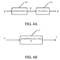
- FIG. 4A shows a sharpening filter and a scaling filter.
- FIG. 4B shows a standalone module with both sharpening and scaling.
- FIG. 5A shows a scaling filter and a sharpening filter.
- FIG. 5B shows a standalone module with both scaling and sharpening.
- FIG. 7 shows a modified 4-tap finite impulse response (FIR) filter circuit for both sharpening and scaling.
- FIG. 8 shows an integrated circuit for calculating the values for the 4 ⁇ 4 matrix of equation Eq. (17).
- FIGS. 9A and 9B show an integrated circuit for calculating equation Eq. (17).
- FIG. 10 shows a block diagram for processing a video signal with a standalone sharpening-scaling filter module.
- FIG. 1 shows a conventional unsharp masking technology 10 .
- contour enhancement of an output video signal y is achieved by adding, via adder 14 , a high-passed (HP) filtered signal from a linear HP filter 12 to the original video signal x.
- HP high-passed
- the equivalent unsharp masking sharpening filter coefficients ⁇ h j , ⁇ n ⁇ j ⁇ n ⁇ are shown in equation Eq. (1) as
- ⁇ g j , ⁇ n ⁇ j ⁇ n ⁇ denote the coefficients of the linear HP filter 12 .
- FIG. 2 shows a conventional sharpening filter 20 .
- the sharpening output y is the convolution between the original video signal x and the sharpening filter 20 , defined by equation Eq. (2)
- the techniques described herein may be used for wireless communications, computing, personal electronics, etc. with a built-in camera module.
- An exemplary use of the techniques for wireless communication is described below.
- FIG. 3 shows a configuration of a wireless device 100 for use in a wireless communication system.
- the wireless device 100 may be a cellular or camera phone, a terminal, a handset, a personal digital assistant (PDA), or some other device.
- the wireless communication system may be a Code Division Multiple Access (CDMA) system, a Global System for Mobile Communications (GSM) system, or some other system.
- CDMA Code Division Multiple Access
- GSM Global System for Mobile Communications
- the wireless device 100 is capable of providing bi-directional communications via a receive path and a transmit path.
- signals transmitted by base stations are received by an antenna 112 and provided to a receiver (RCVR) 114 .
- the receiver 114 conditions and digitizes the received signal and provides samples to a digital section 120 for further processing.
- a transmitter (TMTR) 116 receives data to be transmitted from the digital section 120 , processes and conditions the data, and generates a modulated signal, which is transmitted via the antenna 112 to the base stations.
- the digital section 120 includes various processing, interface and memory units such as, for example, a modem processor 122 , a video processor 124 , a controller/processor 126 , a display processor (DP) 128 , an ARM/DSP 132 , a graphics processing unit (GPU) 134 , an internal memory 136 , and an external bus interface (EBI) 138 .
- the modem processor 122 performs processing for data transmission and reception (e.g., encoding, modulation, demodulation, and decoding).
- the video processor 124 performs processing on video content (e.g., still images, moving videos, and moving texts) for video applications such as camcorder, video playback, and video conferencing.
- the video processor 124 includes a video front end (VFE) 125 .
- the VFE may be a MSM 8600 VFE.
- the video processor 124 performs processing for a camera module 150 having a lens 152 to create still images and/or moving videos.
- the controller/processor 126 may direct the operation of various processing and interface units within the digital section 120 .
- the display processor 128 performs processing to facilitate the display of videos, graphics, and texts on a display unit 130 .
- the ARM/DSP 132 may perform various types of processing for the wireless device 100 .
- the graphics processing unit 134 performs graphics processing of a graphics pipeline.
- the techniques described herein may be used for any of the processors in the digital section 120 , e.g., the video processor 124 .
- the internal memory 136 stores data and/or instructions for various units within the digital section 120 .
- the EBI 138 facilitates the transfer of data between the digital section 120 (e.g., internal memory 136 ) and a main memory 140 along a bus or data line DL.
- the digital section 120 may be implemented with one or more DSPs, micro-processors, RISCs, etc.
- the digital section 120 may also be fabricated on one or more application specific integrated circuits (ASICs) or some other type of integrated circuits (ICs).
- ASICs application specific integrated circuits
- ICs integrated circuits
- the techniques described herein may be implemented in various hardware units.
- the techniques may be implemented in ASICs, DSPs, RISCs, ARMs, digital signal processing devices (DSPDs), programmable logic devices (PLDs), field programmable gate arrays (FPGAs), processors, controllers, micro-controllers, microprocessors, and other electronic units.
- DSPDs digital signal processing devices
- PLDs programmable logic devices
- FPGAs field programmable gate arrays
- processors controllers, micro-controllers, microprocessors, and other electronic units.
- FIG. 4A shows a sharpening filter module 202 and a scaling filter module 204 .
- FIG. 4B shows a standalone module 210 with both sharpening and scaling. Sharpening may be implemented as a standalone module in the DP 128 . However, to relieve the significant amount of the work (such as design, implementation and testing) brought by a new module, it may be better to combine the sharpening module 202 and the scaling module 204 together and use the existing scaling module to do both scaling and sharpening. There are two possible ways for the combination. The first way is to perform sharpening 202 before the scaling 204 , as best seen in FIG. 4A . The second way is shown in FIGS. 5A-5B . In FIG. 5A scaling 302 is performed before sharpening 304 . FIG. 5B shows a standalone module 310 with both scaling and sharpening.
- x, y and z denote the signals before sharpening, after sharpening and after scaling, respectively, and the relationships between y and x as well as z and y are defined in equations Eqs. (3a) and (3b)
- ⁇ c i , ⁇ 1 ⁇ i ⁇ 2 ⁇ represent 4-tap finite impulse response (FIR) filter coefficients for scaling
- q denotes the coordination index after scaling
- s denotes the scaling ratio
- q/s is the coordination index before scaling. Note that the index of y has been scaled by the scaling ratio s since the scaling changes the coordination grid spacing.
- Equation Eq. (8) shows that the scaled sharpened output z q is obtained by the convolution between the original (pre-sharpened and pre-scaled) signals
- the coefficients of the new sharpening-scaling filter ⁇ d i , ⁇ 1 ⁇ i ⁇ 2 ⁇ are derived from the original scaling filter coefficients ⁇ c i , ⁇ 1 ⁇ i ⁇ 2 ⁇ , sharpening filter coefficients ⁇ h i , ⁇ 1 ⁇ i ⁇ 1 ⁇ , forward prediction coefficients ⁇ a i , 1 ⁇ i ⁇ 4 ⁇ and backward prediction coefficients ⁇ b i , 1 ⁇ i ⁇ 4 ⁇ , as described in equation Eq. (9)
- [ d - 1 d 0 d 1 d 2 ] [ h 0 + h - 1 ⁇ b 1 h - 1 0 h 1 ⁇ a 4 h 1 + h - 1 ⁇ b 2 h 0 h - 1 h 1 ⁇ a 3 h - 1 ⁇ b 3 h 1 h 0 h - 1 + h 1 ⁇ a 2 h - 1 ⁇ b 4 0 h 1 h 0 + h 1 ⁇ a 1 ] ⁇ [ c - 1 c 0 c 1 c 2 ] . ( 9 )
- the new sharpening-scaling equation (i.e. Eq. (8)) has the same format as the original scaling equation, (i.e. Eq. (3)) but with different coefficients. Therefore, both sharpening and scaling can be done in one shot with the use of the 32-phase polyphase 4-tap FIR scaling module.
- [ d - 1 d 0 d 1 d 2 ] [ ⁇ 256 + 1 - ⁇ 256 0 0 - ⁇ 256 2 ⁇ ⁇ 256 + 1 - ⁇ 256 0 0 - ⁇ 256 2 ⁇ ⁇ 256 + 1 - ⁇ 256 0 0 - ⁇ 256 ⁇ 256 + 1 ] ⁇ [ c - 1 c 0 c 1 c 2 ] ( 11 ) where the parameter ⁇ is called sharpening strength.
- One sharpening strength yields one set of coefficients ⁇ d i ⁇ . In this example, a 2 , a 3 and a 4 are zero; b 2 , b 3 and b 4 are set to zero; and b 1 and a 1 are set to 1.
- Arbitrary scaling in the DP 128 is achieved by the use of a polyphase structure with 32 phases, and each phase has its own set of FIR filter coefficients.
- ⁇ c p,i , ⁇ 1 ⁇ i ⁇ 2 ⁇ represent the original scaling filter coefficients for phase p
- the new sharpening-scaling filter coefficients for phase p denoted as ⁇ d p,i , ⁇ 1 ⁇ i ⁇ 2 ⁇ , are defined by equation Eq. (12) as
- [ d p , - 1 d p , 0 d p , 1 d p , 2 ] [ ⁇ 256 + 1 - ⁇ 256 0 0 - ⁇ 256 2 ⁇ ⁇ 256 + 1 - ⁇ 256 0 0 - ⁇ 256 2 ⁇ ⁇ 256 + 1 - ⁇ 256 0 0 - ⁇ 256 ⁇ 256 + 1 ] ⁇ [ c p , - 1 c p , 0 c p , 1 c p , 2 ] . ( 12 )
- the original polyphase FIR filter coefficients (bicubic scaling) and the new ones (sharpening+bicubic scaling with sharpening strength 32 and 64) are listed in Tables 1, 2 and 3, below. All of them are in Q9 format where Q9 format is the actual floating point value and is the value specified in the tables downshifted by 9 bits (i.e., divide by 2 9 or 512).
- x, y and z denote the signals before scaling, after scaling and after sharpening, respectively, and the x-y relationships and y-z relationship are expressed as in equations Eqs. (13) and (14)
- Sharpening strength is determined by a user's preference and coding parameters.
- the user's preference is decided by the user.
- Adjusting sharpening strength adaptively according to coding parameters is a mechanism to prevent the unwanted enhancement on annoying coding artifacts.
- a smaller ⁇ is set for I frames and frames closer to the I frames, while a larger ⁇ is set for frames far away from the I frames.
- the threshold ⁇ is also affected by codec type.
- a larger ⁇ is set for a codec with in-loop deblocker or post deblocker/smoothing filter, while a smaller ⁇ is set for a codec without deblocker or any other modules to remove coding artifacts.
- FIG. 7 shows a modified 4-tap FIR filter circuit 400 for both sharpening and scaling.
- a signed eleven-bit resolution (s11) is sufficient for sharpening strength up to 127.
- s11 or 11s represents a signed 11 bits resolution meaning 1 bit to denote a +/ ⁇ sign and 10 bits for the magnitude.
- unsigned bit resolutions are denoted for example as u8.
- the 8 represents the number of bits for the magnitude with no bits for a sign. This nomenclature applies throughout the disclosure and drawings.
- the W represents the sharpening-scaling filter coefficients.
- the resultant signal is 19 bits (19s).
- the output of the multiplier 402 a is downshifted bitwise by 6 (>>6) at block 404 a .
- the block 404 a divides the input by 2 6 .
- the resultant output signal is 13 bits (13s).
- the output of block 404 a is sent to adder 406 .
- the modified 4-tap FIR filter circuit 400 includes four parallel paths.
- the first path includes the multiplier 402 a and downshifter 404 a .
- the second path includes a multiplier 402 b and downshifter 404 b .
- the third path includes a multiplier 402 c and downshifter 404 c .
- the fourth path includes a multiplier 402 d and downshifter 404 d .
- the first through fourth paths function essentially the same.
- adder 406 receives the output from downshifters 404 a , 404 b , 404 c and 404 d.
- the output of adder 406 is sent to block 408 where downshifting bitwise by 2 (>>2) takes place.
- the output of adder 406 is 15 bits (15s).
- the resultant output is 13 bits (13s).
- the output of downshifter 408 is sent to adder 410 where a 1 bit matrix is added.
- the resultant output is now 14 bits (14s).
- the output of the adder 410 is sent to downshifter block 412 to perform a downshift bitwise by 1 or divide by 2 1 .
- the resultant output is now 13 bits (13s).
- the output of the downshifter block 412 is sent to block 414 where the output is clamped to values between [0, 255].
- the resultant output is an eight bit signal (8u).
- sharpening is not applied on chrominance so the original scaling filter coefficients listed in the Table 1 ⁇ C ⁇ are used for chrominance (i.e., only doing scaling no sharpening).
- the new sharpening-scaling coefficients listed in the Table 2 ⁇ D ⁇ are used for luminance (i.e., doing both sharpening and scaling).
- the value W in FIG. 7 is equal to ⁇ D ⁇ for luminance and ⁇ C ⁇ for chrominance.
- FIG. 8 shows an integrated circuit 500 for calculating the values for the 4 ⁇ 4 matrix of equation Eq. (17).
- the integrated circuit 500 includes an adder 502 which receives the value for the sharpening strength ⁇ and a value 256 denoted by [0 ⁇ 100]. This produces a first resultant output of ⁇ +256.
- the sharpening strength ⁇ in input to the adder 502 , an adder 504 and a negate block 506 . Then each of the adder 502 , adder 504 and negate block 506 produce an output. Thus, there are three outputs.
- the adder 504 receives as input the sharpening strength ⁇ and the output of adder 502 . This produces second resultant output 2 ⁇ +256.
- the sharpening strength at the output of block 506 is ⁇ , the third resultant output.
- the first and second resultant outputs from circuit 500 are 9 bits (9u) while the third resultant output is 8 bits (8s).
- FIGS. 9A and 9B show an integrated circuit for calculating equation Eq. (17).
- the integrated circuit is divided into two sub-circuits 600 and 700 .
- the sub-circuit 600 calculates the product of the 4-tap FIR filter coefficients for scaling denoted as ⁇ c i , ⁇ 1 ⁇ i ⁇ 2 ⁇ and the 4 ⁇ 4 matrix of equation Eq. (17).
- the FIR filter coefficients, C p,-1 , C p,0 , C p,1 and C p,2 are 10 bits (10s).
- Each path has a multiplier 602 , 606 , 610 and 614 .
- the multiplier 602 receives the input coefficient C p,-1 and the first resultant output of integrated circuit 500 , ⁇ +256.
- the multiplier 614 receives the input coefficient C p,2 and the first resultant output of integrated circuit 500 , ⁇ +256.
- the multiplier 606 receives the input coefficient C p,0 and the second resultant output of integrated circuit 500 , 2 ⁇ +256.
- the multiplier 610 receives the input coefficient C p,1 and the second resultant output of integrated circuit 500 , 2 ⁇ +256.
- Each of the four paths for inputting the FIR filter coefficients C p,-1 , C p,0 , C p,1 and C p,2 has a parallel branch path.
- the parallel branch path for C p,-1 has multiplier 604 which multiplies C p,-1 and the third resultant output of the integrated circuit 500 , ⁇ .
- the parallel branch path for C p,0 has multiplier 608 which multiplies C p,0 and the third resultant output of the integrated circuit 500 , ⁇ .
- the parallel branch path for C p,1 has multiplier 612 which multiplies C p,1 and the third resultant output of the integrated circuit 500 , ⁇ .
- the parallel branch path for C p,2 has multiplier 616 which multiplies C p2 and the third resultant output of the integrated circuit 500 , ⁇ .
- the first and second resultant outputs of sub-circuit 600 include ( ⁇ +256)C p,-1 and ⁇ C p,-1 from multipliers 602 and 604 , respectively.
- the third and fourth resultant outputs of multipliers 606 and 608 include (2 ⁇ +256)C p,0 and ⁇ C p,0 , respectively.
- the fifth and sixth resultant outputs of multipliers 610 and 612 include (2 ⁇ +256)C p,2 and ⁇ C p,2 , respectively.
- the seventh and eighth resultant outputs of multipliers 614 and 616 include ( ⁇ +256)C p,2 and ⁇ C p,2 .
- These resultant outputs are inputs to sub-circuit 700 of FIG. 9B .
- the first, third, fifth, and seventh resultant outputs are 19 bits (19s).
- the second, fourth, sixth and eighth resultant outputs are 17 bits (17s).
- the sub-circuit 700 calculates the remaining operation of equation Eq. (17) using the inputs from sub-circuit 600 .
- the sub-circuit 700 includes four adders 702 a , 702 b , 702 c and 702 d .
- the adder 702 a adds together the first resultant output ( ⁇ +256)C p,-1 and the fourth resultant output ⁇ C p,0 which produces an output.
- the output of adder 702 a is sent to adder 704 a .
- the adder 704 a adds the output from adder 702 a and a value of 128.
- the output of adder 704 a is sent to a downshifter 706 a where it is downshifted bitwise by 8 (>>8).
- the downshifter 706 a equivalently serves to divide the signal by 2 8 and produces d p,-1 .
- the adder 702 b adds together the second resultant output ⁇ C p,-1 , the third resultant output (2 ⁇ +256)C p,0 and the sixth resultant output ⁇ C p,1 which produces an output.
- the output of adder 702 b is sent to adder 704 b .
- the adder 704 b adds the output from adder 702 b and a value of 128.
- the output of adder 704 b is sent to a downshifter 706 b where it is downshifted bitwise by 8 (>>8).
- the downshifter 706 a equivalently serves to divide the signal by 2 8 and produces d p,0 .
- the adder 702 c adds together the fourth resultant output ⁇ C p,0 , the fifth resultant output (2 ⁇ +256)C p,1 and the eighth resultant output ⁇ C p,2 which produces an output.
- the output of adder 702 c is sent to adder 704 c .
- the adder 704 c adds the output from adder 702 c and a value of 128.
- the output of adder 704 c is sent to a downshifter 706 c where it is downshifted bitwise by 8 (>>8) and produces d p,1 .
- the adder 702 d adds together the sixth resultant output ⁇ C p,1 and the seventh resultant output ( ⁇ +256)C p,2 which produces an output.
- the output of adder 702 d is sent to adder 704 d .
- the adder 704 d adds the output from adder 702 d and a value of 128.
- the output of adder 704 d is sent to a downshifter 706 d where it is downshifted bitwise by 8 (>>8) and produces d p,2 .
- FIG. 10 shows block diagram 800 for processing a video signal with a standalone sharpening-scaling filter module 808 in a DP 128 .
- the block diagram 800 includes a processor circuit 802 which communicates with a coefficient memory 804 .
- the coefficient memory 804 may store the values of the FIR filter coefficients C p,-1 , C p,0 , C p,1 and C p,2 .
- the FIR filter coefficients C p,-1 , C p,0 , C p,1 and C p,2 are read from the coefficient memory 804 and sent to the integrated circuits at block 806 .
- the integrated circuits include circuit 500 and sub-circuits 600 and 700 .
- the output of the integrated circuits at block 806 are the new sharpening-scaling filter coefficients for phase p, denoted as ⁇ d p,i , ⁇ 1 ⁇ i ⁇ 2 ⁇ and are 11 bits.
- the 11-bit new sharpening-scaling filter coefficients ⁇ d p,i , ⁇ 1 ⁇ i ⁇ 2 ⁇ are applied to the sharpening-scaling filter module 808 to generate output Z from the original video signal X.
- the block diagram 800 also shows a sharpening strength adjuster 810 to adaptively adjust the sharpening strength ⁇ to prevent unwanted enhancement on artifacts.
- the adaptive adjustment employs equation Eq. (16) above.
- the equations described herein may be carried out by a processor or a combination of software and hardware.
- the sharpening strength adjuster 810 is shown in a dotted line box to denote that the sharpening strength adjuster 810 may be outside of the DP 128 .
- the sharpening strength adjuster 810 may be in the video processor 124 .
- the coefficient memory 804 is shown in a dotted line box to denote that the coefficient memory 804 may be external to the DP 128 .
- Table 4 illustrates a Hardware interface table with the sharpening strength ⁇ . This can be an input into the integrated circuit 500 of FIG. 8 .
- the overflow problem can be overcome with downshifting the FIR filter coefficients C p,-1 , C p,0 , C p,1 and C p,2 by 1 bit and then compensating back by gamma correction.
- Downshifting coefficients by 1-bit is equivalent to represent a Q8 value (2 8 ) in signed 10 bit resolution. Since the FIR filter coefficients, C p,-1 , C p,0 , C p,1 and C p,2 are divided by two, the new RGB values, after sharpening and scaling, would be only a half of the values it is supposed to be.
- the finite impulse response (FIR) filter taps of the sharpening-scaling filter module may be increased.
- the sharpening-scaling filter module should be ready to adopt changes. Specifically, let m be the number of the taps for the FIR filter (suppose m is an even number), then the equations Eq. (2), (3), and (8) are modified accordingly, as equations Eqs. (18), (19) and (20)
- the functions described may be implemented in hardware, software, firmware, or any combination thereof. If implemented in software, the functions may be stored on or transmitted over as one or more instructions or code on a computer-readable medium.
- Computer-readable media includes both computer storage media and communication media including any medium that facilitates transfer of a computer program from one place to another.
- a storage media may be any available media that can be accessed by a computer.
- such computer-readable media can comprise RAM, ROM, EEPROM, CD-ROM or other optical disk storage, magnetic disk storage or other magnetic storage devices, or any other medium that can be used to carry or store desired program code in the form of instructions or data structures and that can be accessed by a computer.
- any connection is properly termed a computer-readable medium.
- the software is transmitted from a website, server, or other remote source using a coaxial cable, fiber optic cable, twisted pair, digital subscriber line (DSL), or wireless technologies such as infrared, radio, and microwave
- the coaxial cable, fiber optic cable, twisted pair, DSL, or wireless technologies such as infrared, radio, and microwave are included in the definition of medium.
- Disk and disc includes compact disc (CD), laser disc, optical disc, digital versatile disc (DVD), floppy disk and blu-ray disc where disks usually reproduce data magnetically, while discs reproduce data optically with lasers. Combinations of the above should also be included within the scope of computer-readable media.
Abstract
Description
where di are new sharpening-scaling filter coefficients derived from at least sharpening filter coefficients and original scaling filter coefficients of a scaling filter; m denotes an even number of taps; s denotes the scaling ratio; q denotes a coordination index after scaling; and i is an index for a tap of the scaling filter.
where {gj, −n≦j≦n} denote the coefficients of the
where {ci, −1≦i≦2} represent 4-tap finite impulse response (FIR) filter coefficients for scaling; q denotes the coordination index after scaling; s denotes the scaling ratio; and q/s is the coordination index before scaling. Note that the index of y has been scaled by the scaling ratio s since the scaling changes the coordination grid spacing.
To achieve this, linear predictions are used to predict
defined in equations Eq. (6) and Eq. (7)
and a 4-tap sharpening-scaling filter di (−1≦i≦2). The coefficients of the new sharpening-scaling filter {di, −1≦i≦2} are derived from the original scaling filter coefficients {ci, −1≦i≦2}, sharpening filter coefficients {hi, −1≦i≦1}, forward prediction coefficients {ai, 1≦i≦4} and backward prediction coefficients {bi, 1≦i≦4}, as described in equation Eq. (9)
where rk is the autocorrelation value, rk=E(xnxn-k). Similar equation is used for the optimal backward predictor coefficients {{circumflex over (b)}i, 1≦i≦4}.
and
where the parameter α is called sharpening strength. One sharpening strength yields one set of coefficients {di}. In this example, a2, a3 and a4 are zero; b2, b3 and b4 are set to zero; and b1 and a1 are set to 1.
| TABLE 1 |
| Polyphase FIR filter coefficients for bicubic scaling |
| Phase | cp,−1 | cp,0 | cp,1 | cp,2 |
| 0 | 0 | 512 | 0 | 0 |
| 1 | −7 | 510 | 8 | 0 |
| 2 | −14 | 507 | 19 | 0 |
| 3 | −19 | 501 | 32 | −2 |
| 4 | −24 | 493 | 46 | −3 |
| 5 | −28 | 483 | 62 | −5 |
| 6 | −31 | 472 | 78 | −7 |
| 7 | −34 | 458 | 96 | −9 |
| 8 | −36 | 444 | 116 | −12 |
| 9 | −37 | 427 | 135 | −14 |
| 10 | −37 | 410 | 156 | −17 |
| 11 | −37 | 391 | 177 | −19 |
| 12 | −37 | 372 | 199 | −22 |
| 13 | −36 | 352 | 221 | −25 |
| 14 | −35 | 331 | 243 | −27 |
| 15 | −33 | 309 | 265 | −29 |
| 16 | −32 | 288 | 288 | −32 |
| 17 | −29 | 265 | 309 | −33 |
| 18 | −27 | 243 | 331 | −35 |
| 19 | −25 | 221 | 352 | −36 |
| 20 | −22 | 199 | 372 | −37 |
| 21 | −19 | 177 | 391 | −37 |
| 22 | −17 | 156 | 410 | −37 |
| 23 | −14 | 135 | 427 | −37 |
| 24 | −12 | 116 | 444 | −36 |
| 25 | −9 | 96 | 458 | −34 |
| 26 | −7 | 78 | 472 | −31 |
| 27 | −5 | 62 | 483 | −28 |
| 28 | −3 | 46 | 493 | −24 |
| 29 | −2 | 32 | 501 | −19 |
| 30 | 0 | 19 | 507 | −14 |
| 31 | 0 | 8 | 510 | −7 |
| TABLE 2 |
| Polyphase FIR filter coefficients for |
| sharpening + scaling (sharpening strength α = 32) |
| Phase | dp,−1 | dp,0 | dp,1 | dp,2 |
| 0 | −64 | 640 | −64 | 0 |
| 1 | −72 | 638 | −52 | −1 |
| 2 | −79 | 633 | −38 | −3 |
| 3 | −84 | 625 | −21 | −6 |
| 4 | −89 | 614 | −3 | −9 |
| 5 | −92 | 600 | 17 | −13 |
| 6 | −94 | 584 | 40 | −18 |
| 7 | −95 | 565 | 65 | −22 |
| 8 | −96 | 545 | 91 | −28 |
| 9 | −95 | 522 | 118 | −33 |
| 10 | −93 | 498 | 146 | −38 |
| 11 | −91 | 472 | 175 | −44 |
| 12 | −88 | 445 | 205 | −50 |
| 13 | −85 | 417 | 235 | −55 |
| 14 | −81 | 388 | 266 | −61 |
| 15 | −76 | 358 | 297 | −66 |
| 16 | −72 | 328 | 328 | −72 |
| 17 | −66 | 297 | 358 | −76 |
| 18 | −61 | 266 | 388 | −81 |
| 19 | −55 | 235 | 417 | −85 |
| 20 | −50 | 205 | 445 | −88 |
| 21 | −44 | 175 | 472 | −91 |
| 22 | −38 | 146 | 498 | −93 |
| 23 | −33 | 118 | 522 | −95 |
| 24 | −28 | 91 | 545 | −96 |
| 25 | −22 | 65 | 565 | −95 |
| 26 | −18 | 40 | 584 | −94 |
| 27 | −13 | 17 | 600 | −92 |
| 28 | −9 | −3 | 614 | −89 |
| 29 | −6 | −21 | 625 | −84 |
| 30 | −3 | −38 | 633 | −79 |
| 31 | −1 | −52 | 638 | −72 |
| TABLE 3 |
| Polyphase FIR filter coefficients for |
| sharpening + scaling (sharpening strength α = 64). |
| Phase | dp,−1 | dp,0 | dp,1 | dp,2 |
| 0 | −128 | 768 | −128 | 0 |
| 1 | −137 | 765 | −114 | −2 |
| 2 | −144 | 759 | −96 | −6 |
| 3 | −149 | 748 | −76 | −10 |
| 4 | −154 | 734 | −52 | −16 |
| 5 | −156 | 717 | −26 | −22 |
| 6 | −157 | 696 | 2 | −28 |
| 7 | −157 | 672 | 33 | −36 |
| 8 | −156 | 646 | 66 | −44 |
| 9 | −153 | 617 | 100 | −52 |
| 10 | −149 | 585 | 136 | −60 |
| 11 | −145 | 552 | 173 | −69 |
| 12 | −140 | 518 | 211 | −78 |
| 13 | −133 | 482 | 250 | −86 |
| 14 | −127 | 444 | 289 | −95 |
| 15 | −119 | 406 | 328 | −103 |
| 16 | −112 | 368 | 368 | −112 |
| 17 | −103 | 328 | 406 | −119 |
| 18 | −95 | 289 | 444 | −127 |
| 19 | −86 | 250 | 482 | −133 |
| 20 | −78 | 211 | 518 | −140 |
| 21 | −69 | 173 | 552 | −145 |
| 22 | −60 | 136 | 585 | −149 |
| 23 | −52 | 100 | 617 | −153 |
| 24 | −44 | 66 | 646 | −156 |
| 25 | −36 | 33 | 672 | −157 |
| 26 | −28 | 2 | 696 | −157 |
| 27 | −22 | −26 | 717 | −156 |
| 28 | −16 | −52 | 734 | −154 |
| 29 | −10 | −76 | 748 | −149 |
| 30 | −6 | −96 | 759 | −144 |
| 31 | −2 | −114 | 765 | −137 |
Combine Scaling with a Post-Sharpening Filter
where s represents the scaling ratio. Placing Eq. (13) into Eq. (14) achieves equation Eq. (15)
where n is the number of the sharpening filter taps.
α=max(α0 −k(max(0,Qp−τ)),αmin) (16)
where αmin is the minimum sharpening strength; τ is a threshold determined by the distance to the last I frame and codec type; k is a tunable constant; Qp is a quantization step size; and α0 is a default sharpening strength. A smaller τ is set for I frames and frames closer to the I frames, while a larger τ is set for frames far away from the I frames. The threshold τ is also affected by codec type. A larger τ is set for a codec with in-loop deblocker or post deblocker/smoothing filter, while a smaller τ is set for a codec without deblocker or any other modules to remove coding artifacts.
HW Changes and HW Interface for New DPs
where the hardware implementation of above equation is illustrated in
| TABLE 4 |
| Hardware interface |
| Description and Value | Programming | ||
| Name | Bits | range | Frequency |
| sharpening_strength | S8 | Sharpening strength α, | Occasionally |
| [−127, 127] | (change due to | ||
| users' preference | |||
| or QPs) | |||
Sharpening Implementation
| TABLE 5 |
| New LUT to Compensate for overflow |
| Original | New | ||
| Mapped value | mapped | ||
| 0 | gc0 | Max(255, 2 * gc0) |
| 1 | gc1 | Max(255, 2 * gc1) |
| 2 | gc2 | Max(255, 2 * gc2) |
| . . . |
| 255 | gc255 | Max(255, 2 * gc255) |
Extend to m-Tap Filter
and the original scaling filter coefficients
is shown in equation Eq. (21)
Claims (25)
α=max(α0 −k(max(0,Qp−τ)),αmin)
α=max(α0 −k(max(0,Qp−τ)),αmi)
Priority Applications (6)
| Application Number | Priority Date | Filing Date | Title |
|---|---|---|---|
| US11/781,797 US8073282B2 (en) | 2007-07-23 | 2007-07-23 | Scaling filter for video sharpening |
| AT08006402T ATE493722T1 (en) | 2007-07-23 | 2008-03-31 | SCALING FILTER TO IMPROVE VIDEO IMAGE SHARPNESS |
| EP08006402A EP2028618B1 (en) | 2007-07-23 | 2008-03-31 | Scaling filter for video sharpening |
| DE602008004192T DE602008004192D1 (en) | 2007-07-23 | 2008-03-31 | Scaling filter to improve video clarity |
| TW097128009A TW200919374A (en) | 2007-07-23 | 2008-07-23 | Scaling filter for video sharpening |
| PCT/US2008/070907 WO2009015217A2 (en) | 2007-07-23 | 2008-07-23 | Scaling filter for video sharpening |
Applications Claiming Priority (1)
| Application Number | Priority Date | Filing Date | Title |
|---|---|---|---|
| US11/781,797 US8073282B2 (en) | 2007-07-23 | 2007-07-23 | Scaling filter for video sharpening |
Publications (2)
| Publication Number | Publication Date |
|---|---|
| US20090028458A1 US20090028458A1 (en) | 2009-01-29 |
| US8073282B2 true US8073282B2 (en) | 2011-12-06 |
Family
ID=39876735
Family Applications (1)
| Application Number | Title | Priority Date | Filing Date |
|---|---|---|---|
| US11/781,797 Expired - Fee Related US8073282B2 (en) | 2007-07-23 | 2007-07-23 | Scaling filter for video sharpening |
Country Status (6)
| Country | Link |
|---|---|
| US (1) | US8073282B2 (en) |
| EP (1) | EP2028618B1 (en) |
| AT (1) | ATE493722T1 (en) |
| DE (1) | DE602008004192D1 (en) |
| TW (1) | TW200919374A (en) |
| WO (1) | WO2009015217A2 (en) |
Cited By (2)
| Publication number | Priority date | Publication date | Assignee | Title |
|---|---|---|---|---|
| US9712834B2 (en) | 2013-10-01 | 2017-07-18 | Dolby Laboratories Licensing Corporation | Hardware efficient sparse FIR filtering in video codec |
| US11949395B1 (en) * | 2021-05-14 | 2024-04-02 | Xilinx, Inc. | Polyphase filter control scheme for fractional resampler systems |
Families Citing this family (3)
| Publication number | Priority date | Publication date | Assignee | Title |
|---|---|---|---|---|
| US8885967B2 (en) * | 2009-01-19 | 2014-11-11 | Csr Technology Inc. | Method and apparatus for content adaptive sharpness enhancement |
| US8503814B2 (en) * | 2009-01-19 | 2013-08-06 | Csr Technology Inc. | Method and apparatus for spectrum estimation |
| DE102011075261A1 (en) * | 2011-05-04 | 2012-11-08 | Robert Bosch Gmbh | Method for editing video data and an arrangement for carrying out the method |
Citations (9)
| Publication number | Priority date | Publication date | Assignee | Title |
|---|---|---|---|---|
| US5422827A (en) * | 1993-02-12 | 1995-06-06 | Cirrus Logic, Inc. | Integrated video scaling and sharpening filter |
| US6281873B1 (en) * | 1997-10-09 | 2001-08-28 | Fairchild Semiconductor Corporation | Video line rate vertical scaler |
| WO2003036943A1 (en) | 2001-10-26 | 2003-05-01 | Koninklijke Philips Electronics N.V. | Polyphase filter combining vertical peaking and scaling in pixel-processing arrangement |
| US20040086038A1 (en) * | 2002-04-23 | 2004-05-06 | Daniel Kilbank | System and method for using microlets in communications |
| US6738072B1 (en) * | 1998-11-09 | 2004-05-18 | Broadcom Corporation | Graphics display system with anti-flutter filtering and vertical scaling feature |
| US7259796B2 (en) * | 2004-05-07 | 2007-08-21 | Micronas Usa, Inc. | System and method for rapidly scaling and filtering video data |
| US7408590B2 (en) * | 2004-05-07 | 2008-08-05 | Micronas Usa, Inc. | Combined scaling, filtering, and scan conversion |
| US7411628B2 (en) * | 2004-05-07 | 2008-08-12 | Micronas Usa, Inc. | Method and system for scaling, filtering, scan conversion, panoramic scaling, YC adjustment, and color conversion in a display controller |
| US7782401B1 (en) * | 2006-06-20 | 2010-08-24 | Kolorific, Inc. | Method and system for digital image scaling with sharpness enhancement and transient improvement |
-
2007
- 2007-07-23 US US11/781,797 patent/US8073282B2/en not_active Expired - Fee Related
-
2008
- 2008-03-31 AT AT08006402T patent/ATE493722T1/en not_active IP Right Cessation
- 2008-03-31 EP EP08006402A patent/EP2028618B1/en not_active Not-in-force
- 2008-03-31 DE DE602008004192T patent/DE602008004192D1/en active Active
- 2008-07-23 TW TW097128009A patent/TW200919374A/en unknown
- 2008-07-23 WO PCT/US2008/070907 patent/WO2009015217A2/en active Application Filing
Patent Citations (10)
| Publication number | Priority date | Publication date | Assignee | Title |
|---|---|---|---|---|
| US5422827A (en) * | 1993-02-12 | 1995-06-06 | Cirrus Logic, Inc. | Integrated video scaling and sharpening filter |
| US6281873B1 (en) * | 1997-10-09 | 2001-08-28 | Fairchild Semiconductor Corporation | Video line rate vertical scaler |
| US6738072B1 (en) * | 1998-11-09 | 2004-05-18 | Broadcom Corporation | Graphics display system with anti-flutter filtering and vertical scaling feature |
| WO2003036943A1 (en) | 2001-10-26 | 2003-05-01 | Koninklijke Philips Electronics N.V. | Polyphase filter combining vertical peaking and scaling in pixel-processing arrangement |
| US20030080981A1 (en) * | 2001-10-26 | 2003-05-01 | Koninklijke Philips Electronics N.V. | Polyphase filter combining vertical peaking and scaling in pixel-processing arrangement |
| US20040086038A1 (en) * | 2002-04-23 | 2004-05-06 | Daniel Kilbank | System and method for using microlets in communications |
| US7259796B2 (en) * | 2004-05-07 | 2007-08-21 | Micronas Usa, Inc. | System and method for rapidly scaling and filtering video data |
| US7408590B2 (en) * | 2004-05-07 | 2008-08-05 | Micronas Usa, Inc. | Combined scaling, filtering, and scan conversion |
| US7411628B2 (en) * | 2004-05-07 | 2008-08-12 | Micronas Usa, Inc. | Method and system for scaling, filtering, scan conversion, panoramic scaling, YC adjustment, and color conversion in a display controller |
| US7782401B1 (en) * | 2006-06-20 | 2010-08-24 | Kolorific, Inc. | Method and system for digital image scaling with sharpness enhancement and transient improvement |
Non-Patent Citations (2)
| Title |
|---|
| European Search Report-EP08006402-Search Authority-Munich-May 13, 2009. |
| International Search Report and Written Opinion-PCT/US2008/070907, International Search Authority-European Patent Office-May 20, 2009. |
Cited By (3)
| Publication number | Priority date | Publication date | Assignee | Title |
|---|---|---|---|---|
| US9712834B2 (en) | 2013-10-01 | 2017-07-18 | Dolby Laboratories Licensing Corporation | Hardware efficient sparse FIR filtering in video codec |
| US10182235B2 (en) | 2013-10-01 | 2019-01-15 | Dolby Laboratories Licensing Corporation | Hardware efficient sparse FIR filtering in layered video coding |
| US11949395B1 (en) * | 2021-05-14 | 2024-04-02 | Xilinx, Inc. | Polyphase filter control scheme for fractional resampler systems |
Also Published As
| Publication number | Publication date |
|---|---|
| WO2009015217A3 (en) | 2009-07-02 |
| DE602008004192D1 (en) | 2011-02-10 |
| WO2009015217A2 (en) | 2009-01-29 |
| ATE493722T1 (en) | 2011-01-15 |
| US20090028458A1 (en) | 2009-01-29 |
| EP2028618B1 (en) | 2010-12-29 |
| EP2028618A2 (en) | 2009-02-25 |
| EP2028618A3 (en) | 2009-06-17 |
| TW200919374A (en) | 2009-05-01 |
Similar Documents
| Publication | Publication Date | Title |
|---|---|---|
| JP6039763B2 (en) | Method, apparatus and storage medium for local tone mapping | |
| EP2748792B1 (en) | Image processing for hdr images | |
| US7903898B2 (en) | Visual processing apparatus, visual processing method, program, recording medium, display device, and integrated circuit | |
| US20090232401A1 (en) | Visual processing apparatus, display apparatus, visual processing method, program, and integrated circuit | |
| JP2001275015A (en) | Circuit and method for image processing | |
| JP2008159071A (en) | Visual processing device, visual processing method, program, display device, and integrated circuit | |
| US8073282B2 (en) | Scaling filter for video sharpening | |
| US20120301012A1 (en) | Image signal processing device and image signal processing method | |
| WO2007064341A2 (en) | Combined scaling, filtering, and scan conversion | |
| EP4078526B1 (en) | Noise synthesis for digital images | |
| CN114170341A (en) | Image processing method, device, equipment and medium | |
| EP3556093A1 (en) | Color grading interpolation methods and devices | |
| EP2008241B1 (en) | Image scaling method and apparatus | |
| US20040076334A1 (en) | Method for resizing images using the inverse discrete cosine transform | |
| US20180007239A1 (en) | Signal correction method and apparatus, and terminal | |
| WO2010137387A1 (en) | Image processing device and program | |
| JP3853257B2 (en) | Mosquito distortion reducing apparatus and mosquito distortion reducing method | |
| JPH04333989A (en) | Image enlarging device | |
| JP2024505493A (en) | Image enhancement via global and local reshaping | |
| JP2005354521A (en) | Image processing circuit and image display device |
Legal Events
| Date | Code | Title | Description |
|---|---|---|---|
| AS | Assignment |
Owner name: QUALCOMM INCORPORATED, CALIFORNIA Free format text: ASSIGNMENT OF ASSIGNORS INTEREST;ASSIGNORS:CHEN, CHIA-YUAN;LAI, KING-CHUNG;REEL/FRAME:019601/0244;SIGNING DATES FROM 20070717 TO 20070718 Owner name: QUALCOMM INCORPORATED, CALIFORNIA Free format text: ASSIGNMENT OF ASSIGNORS INTEREST;ASSIGNORS:CHEN, CHIA-YUAN;LAI, KING-CHUNG;SIGNING DATES FROM 20070717 TO 20070718;REEL/FRAME:019601/0244 |
|
| AS | Assignment |
Owner name: QUALCOMM INCORPORATED, CALIFORNIA Free format text: CORRECTIVE ASSIGNMENT TO CORRECT THE FIRST-NAMED INVENTOR'S LAST NAME FROM CHEN TO TENG, PREVIOUSLY RECORDED ON REEL 019601 FRAME 0244;ASSIGNORS:TENG, CHIA YUAN;LAI, KING CHUNG;REEL/FRAME:019721/0670;SIGNING DATES FROM 20070717 TO 20070718 Owner name: QUALCOMM INCORPORATED, CALIFORNIA Free format text: CORRECTIVE ASSIGNMENT TO CORRECT THE FIRST-NAMED INVENTOR'S LAST NAME FROM CHEN TO TENG, PREVIOUSLY RECORDED ON REEL 019601 FRAME 0244. ASSIGNOR(S) HEREBY CONFIRMS THE LAST NAME OF THE FIRST-NAMED INVENTOR SHOULD BE AMENDED FROM CHEN TO TENG;ASSIGNORS:TENG, CHIA YUAN;LAI, KING CHUNG;SIGNING DATES FROM 20070717 TO 20070718;REEL/FRAME:019721/0670 |
|
| STCF | Information on status: patent grant |
Free format text: PATENTED CASE |
|
| FPAY | Fee payment |
Year of fee payment: 4 |
|
| FEPP | Fee payment procedure |
Free format text: MAINTENANCE FEE REMINDER MAILED (ORIGINAL EVENT CODE: REM.); ENTITY STATUS OF PATENT OWNER: LARGE ENTITY |
|
| LAPS | Lapse for failure to pay maintenance fees |
Free format text: PATENT EXPIRED FOR FAILURE TO PAY MAINTENANCE FEES (ORIGINAL EVENT CODE: EXP.); ENTITY STATUS OF PATENT OWNER: LARGE ENTITY |
|
| STCH | Information on status: patent discontinuation |
Free format text: PATENT EXPIRED DUE TO NONPAYMENT OF MAINTENANCE FEES UNDER 37 CFR 1.362 |
|
| FP | Lapsed due to failure to pay maintenance fee |
Effective date: 20191206 |