US8073019B2 - 810 nm ultra-short pulsed fiber laser - Google Patents
810 nm ultra-short pulsed fiber laser Download PDFInfo
- Publication number
- US8073019B2 US8073019B2 US12/715,596 US71559610A US8073019B2 US 8073019 B2 US8073019 B2 US 8073019B2 US 71559610 A US71559610 A US 71559610A US 8073019 B2 US8073019 B2 US 8073019B2
- Authority
- US
- United States
- Prior art keywords
- fiber
- laser
- pulse
- input
- output
- Prior art date
- Legal status (The legal status is an assumption and is not a legal conclusion. Google has not performed a legal analysis and makes no representation as to the accuracy of the status listed.)
- Expired - Fee Related
Links
Images


Classifications
-
- H—ELECTRICITY
- H01—ELECTRIC ELEMENTS
- H01S—DEVICES USING THE PROCESS OF LIGHT AMPLIFICATION BY STIMULATED EMISSION OF RADIATION [LASER] TO AMPLIFY OR GENERATE LIGHT; DEVICES USING STIMULATED EMISSION OF ELECTROMAGNETIC RADIATION IN WAVE RANGES OTHER THAN OPTICAL
- H01S3/00—Lasers, i.e. devices using stimulated emission of electromagnetic radiation in the infrared, visible or ultraviolet wave range
- H01S3/23—Arrangements of two or more lasers not provided for in groups H01S3/02 - H01S3/22, e.g. tandem arrangements of separate active media
- H01S3/2308—Amplifier arrangements, e.g. MOPA
-
- H—ELECTRICITY
- H01—ELECTRIC ELEMENTS
- H01S—DEVICES USING THE PROCESS OF LIGHT AMPLIFICATION BY STIMULATED EMISSION OF RADIATION [LASER] TO AMPLIFY OR GENERATE LIGHT; DEVICES USING STIMULATED EMISSION OF ELECTROMAGNETIC RADIATION IN WAVE RANGES OTHER THAN OPTICAL
- H01S3/00—Lasers, i.e. devices using stimulated emission of electromagnetic radiation in the infrared, visible or ultraviolet wave range
- H01S3/05—Construction or shape of optical resonators; Accommodation of active medium therein; Shape of active medium
- H01S3/06—Construction or shape of active medium
- H01S3/063—Waveguide lasers, i.e. whereby the dimensions of the waveguide are of the order of the light wavelength
- H01S3/067—Fibre lasers
- H01S3/06754—Fibre amplifiers
-
- H—ELECTRICITY
- H01—ELECTRIC ELEMENTS
- H01S—DEVICES USING THE PROCESS OF LIGHT AMPLIFICATION BY STIMULATED EMISSION OF RADIATION [LASER] TO AMPLIFY OR GENERATE LIGHT; DEVICES USING STIMULATED EMISSION OF ELECTROMAGNETIC RADIATION IN WAVE RANGES OTHER THAN OPTICAL
- H01S2302/00—Amplification / lasing wavelength
-
- H—ELECTRICITY
- H01—ELECTRIC ELEMENTS
- H01S—DEVICES USING THE PROCESS OF LIGHT AMPLIFICATION BY STIMULATED EMISSION OF RADIATION [LASER] TO AMPLIFY OR GENERATE LIGHT; DEVICES USING STIMULATED EMISSION OF ELECTROMAGNETIC RADIATION IN WAVE RANGES OTHER THAN OPTICAL
- H01S3/00—Lasers, i.e. devices using stimulated emission of electromagnetic radiation in the infrared, visible or ultraviolet wave range
- H01S3/005—Optical devices external to the laser cavity, specially adapted for lasers, e.g. for homogenisation of the beam or for manipulating laser pulses, e.g. pulse shaping
- H01S3/0057—Temporal shaping, e.g. pulse compression, frequency chirping
-
- H—ELECTRICITY
- H01—ELECTRIC ELEMENTS
- H01S—DEVICES USING THE PROCESS OF LIGHT AMPLIFICATION BY STIMULATED EMISSION OF RADIATION [LASER] TO AMPLIFY OR GENERATE LIGHT; DEVICES USING STIMULATED EMISSION OF ELECTROMAGNETIC RADIATION IN WAVE RANGES OTHER THAN OPTICAL
- H01S3/00—Lasers, i.e. devices using stimulated emission of electromagnetic radiation in the infrared, visible or ultraviolet wave range
- H01S3/005—Optical devices external to the laser cavity, specially adapted for lasers, e.g. for homogenisation of the beam or for manipulating laser pulses, e.g. pulse shaping
- H01S3/0092—Nonlinear frequency conversion, e.g. second harmonic generation [SHG] or sum- or difference-frequency generation outside the laser cavity
-
- H—ELECTRICITY
- H01—ELECTRIC ELEMENTS
- H01S—DEVICES USING THE PROCESS OF LIGHT AMPLIFICATION BY STIMULATED EMISSION OF RADIATION [LASER] TO AMPLIFY OR GENERATE LIGHT; DEVICES USING STIMULATED EMISSION OF ELECTROMAGNETIC RADIATION IN WAVE RANGES OTHER THAN OPTICAL
- H01S3/00—Lasers, i.e. devices using stimulated emission of electromagnetic radiation in the infrared, visible or ultraviolet wave range
- H01S3/09—Processes or apparatus for excitation, e.g. pumping
- H01S3/091—Processes or apparatus for excitation, e.g. pumping using optical pumping
- H01S3/094—Processes or apparatus for excitation, e.g. pumping using optical pumping by coherent light
- H01S3/094092—Upconversion pumping
-
- H—ELECTRICITY
- H01—ELECTRIC ELEMENTS
- H01S—DEVICES USING THE PROCESS OF LIGHT AMPLIFICATION BY STIMULATED EMISSION OF RADIATION [LASER] TO AMPLIFY OR GENERATE LIGHT; DEVICES USING STIMULATED EMISSION OF ELECTROMAGNETIC RADIATION IN WAVE RANGES OTHER THAN OPTICAL
- H01S3/00—Lasers, i.e. devices using stimulated emission of electromagnetic radiation in the infrared, visible or ultraviolet wave range
- H01S3/14—Lasers, i.e. devices using stimulated emission of electromagnetic radiation in the infrared, visible or ultraviolet wave range characterised by the material used as the active medium
- H01S3/16—Solid materials
- H01S3/1601—Solid materials characterised by an active (lasing) ion
- H01S3/1603—Solid materials characterised by an active (lasing) ion rare earth
- H01S3/1616—Solid materials characterised by an active (lasing) ion rare earth thulium
Definitions
- the invention relates generally to the field of ultra-short pulse fiber lasers operating at wavelengths around 810 nm.
- an ultra-short pulse fiber laser comprising: a seed fiber laser; a pulse stretcher comprising an input and an output, wherein the seed fiber laser is coupled to the input of the pulse stretcher; a Tm:ZBLAN fiber comprising an input and an output, wherein the output of the pulse stretcher is coupled to the input of the Tm:ZBLAN fiber; a pump laser coupled to the output of the Tm:ZBLAN fiber; and a compressor comprising an input and an output, wherein the output of the TM:ZBLAN fiber is coupled to the input of the compressor and the output of the compressor is configured to emit a laser pulse.
- an ultra-short pulse fiber laser comprising: a seed fiber laser; a pulse stretcher comprising an input and an output, wherein the seed fiber laser is coupled to the input of the pulse stretcher; a Tm:ZBLAN fiber comprising an input and an output, wherein the output of the pulse stretcher is coupled to the input of the Tm:ZBLAN fiber; a pump laser coupled to the input of the Tm:ZBLAN fiber; and a compressor comprising an input and an output, wherein the output of the TM:ZBLAN fiber is coupled to the input of the compressor and the output of the compressor is configured to emit a laser pulse.
- a method for generating ultra-short fiber laser pulses comprising: generating a signal laser pulse from a seed fiber laser; using a pulse stretcher comprising an input and an output, wherein the signal laser pulse is coupled into the input of the pulse stretcher; using a Tm:ZBLAN fiber comprising an input and an output, wherein the stretched signal laser pulse from the output of the pulse stretcher is coupled into the input of the Tm:ZBLAN fiber; using a pump laser coupled to the output of the Tm:ZBLAN fiber to amplify the stretched signal laser pulse; and using a compressor comprising an input and an output, wherein the output of the Tm:ZBLAN fiber is coupled to the input of the compressor and the output of the compressor emits the amplified signal laser pulse.
- a method for generating ultra-short fiber laser pulses comprising: generating a signal laser pulse from a seed fiber laser; using a pulse stretcher comprising an input and an output, wherein the signal laser pulse is coupled into the input of the pulse stretcher; using a Tm:ZBLAN fiber comprising an input and an output, wherein the stretched signal laser pulse from the output of the pulse stretcher is coupled into the input of the Tm:ZBLAN fiber; using a pump laser coupled to the input of the Tm:ZBLAN fiber to amplify the stretched signal laser pulse; and using a compressor comprising an input and an output, wherein the output of the Tm:ZBLAN fiber is coupled to the input of the compressor and the output of the compressor emits the amplified signal laser pulse.
- FIG. 1 is a block diagram illustrating an ultra-short pulse fiber laser, in accordance with some embodiments.
- FIG. 2 is a partial energy level diagram of Tm:ZBLAN fiber illustrating the upconversion mechanism, in accordance with some embodiments.
- FIG. 3 is a schematic representation of the Tm:ZBLAN fiber upconversion amplifier employing the chirped pulse amplification technique and fiber lasers as seed and pump, in accordance with some embodiments.
- FIG. 4 is a schematic representation of the Tm:ZBLAN fiber upconversion amplifier employing all fiber components, in accordance with some embodiments.
- FIG. 5 is a block diagram illustrating a method for generating an ultra-short fiber laser pulse, in accordance with some embodiments.
- Ti:Sapphire solid state laser One way to produce ultra-short pulses is to use a Ti:Sapphire solid state laser.
- Conventional Ti:Sapphire solid state laser systems are physically bulky and are expensive to purchase and maintain. Fiber lasers on the other hand are more compact and cheaper to purchase and maintain.
- the power and energy levels of typical fiber lasers at 1550 nm and even the second harmonic generation between 750 nm-810 nm is on the order of tens of milliwatts. These power levels are lower than conventional Ti:Sapphire solid state laser power levels and therefore fiber laser power levels need to be raised in order for fiber lasers to replace conventional Ti:Sapphire solid state lasers.
- One such laser, a fiber based, high power, ultrafast fiber laser operating at 750 nm-850 nm is disclosed in this patent.
- FIG. 1 is a block diagram illustrating an ultra-short pulse fiber laser, in accordance with some embodiments.
- a pulsed fiber laser 110 operating at 750 nm-850 nm comprises a seed fiber laser 115 , such as a 1550 nm femtosecond (fs) fiber laser, coupled into a second harmonic generation (SHG) module 120 operating between 10 mW to 200 mW at a wavelength around 810 nm.
- the output from the SHG module 120 is then coupled to a stretcher 125 , such as a fiber stretcher, a grating pair stretcher, or a glass stretcher, to stretch the seed pulse before being coupled to a Tm:ZBLAN fiber 130 .
- a pump laser 135 pumps the Tm:ZBLAN fiber 130 and amplifies the seed pulse by utilizing an upconversion mechanism of the Tm:ZBLAN fiber 130 .
- the pulse is compressed by a grating compressor 140 . What results are high power, femtosecond pulses 145 at 810 nm emitted from the pulsed fiber laser 110 .
- FIG. 2 is a partial energy level diagram of Tm:ZBLAN fiber illustrating the upconversion mechanism, in accordance with some embodiments.
- the upconversion process of Tm:ZBLAN fiber causes an increased excited state absorption (ESA) from state 3 F 4 to state 3 F 2 , 210 .
- ESA excited state absorption
- TM Thulium
- TM Thulium
- This process results in the necessary population inversion from the ground state 3 H 6 to the upper level energy state 3 H 4 .
- This process is similar to that in Er:ZBLAN fiber where the lower level state 4 H 13/2 is depopulated quickly and efficiently by either ESA or energy transfer.
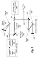
- FIG. 3 is a schematic representation of the Tm:ZBLAN fiber upconversion amplifier employing the chirped pulse amplification technique and fiber lasers as seed and pump, in accordance with some embodiments.
- a Tm:ZBLAN fiber and a pump fiber laser are used for the chirped pulse amplification of ultra-short pulses.
- the seed laser 310 comprises an Er-doped fiber laser system 315 operating at 1550 nm-1620 nm and a second harmonic generator 320 to frequency double.
- the seed fiber laser 310 produces femtosecond pulses at 810 nm.
- the Mercury series from PolarOnyx, Inc. may be used as the seed laser 310 .
- the signal pulse from the seed laser 310 is stretched to longer pulse duration in order to avoid intensity saturation and damage to the amplifier.
- the signal pulse is stretched to 1 ps to 10 ns by a positive group velocity delay using a grating stretcher 325 , such as a four-pass stretcher.
- the grating stretcher 325 has a grating 330 with 2400 lines per mm and is arranged in a folded, double pass geometry with an incident angle near the Littrow angle of 72° in order to achieve better efficiency.
- the stretched pulse is next coupled into the Tm:ZBLAN fiber 335 by a 5 ⁇ microscope objective 340 .
- the Tm:ZBLAN fiber 335 may comprise single mode core or multimode core fiber and may either be single cladding or double cladding fiber.
- the Tm:ZBLAN fiber 335 is pumped by a wavelength in the spectral range of 950 nm-1200 nm.
- One such laser is a CW high power 1064 nm fiber laser 345 coupled with a dichroic mirror 350 arranged either to counter-propagate or co-propagate with the stretched signal.
- the counter-propagation arrangement results in a higher amplification than the co-propagation arrangement.
- the counter-propagation arrangement is illustrated in FIG. 3 .
- the pump laser 345 may be the Mars Series from PolarOnyx, Inc.
- the amplified pulses have pulse widths ranging from 1 ps to 1 ⁇ s and have a pulse repetition rate between 1 Hz to 1 GHz.
- the signal pulse is compressed by a grating compressor 355 comprised of a pair of gratings 360 having 2400 lines per mm.
- the high power, ultra-short laser pulses 365 are output using a high reflectivity mirror 370 .
- the laser pulses 365 are in the wavelength range from 750 nm-850 nm and have pulse energy ranging from 1 nJ to 1 mJ with pulse widths ranging from 10 fs to 100 ps.
- various high reflectivity mirrors 375 and 380 are utilized to direct the laser pulse. In high reflectivity mirrors 370 and 380 , the incoming and outgoing light does not overlap.
- FIG. 4 is a schematic representation of the Tm:ZBLAN fiber upconversion amplifier employing all fiber components, in accordance with some embodiments.
- a Tm:ZBLAN fiber amplifier may use all fiber components for the chirped amplification of ultra-short pulses. Using all fiber components eliminates the complexity of free space components.
- the seed laser 410 comprises an Er-doped fiber laser system 415 operating at 1550 nm-1620 nm and a second harmonic generator 420 to frequency double.
- the seed fiber laser 410 produces femtosecond pulses at 810 nm.
- the Mercury series from PolarOnyx, Inc. may be used as the seed laser 410 .
- the signal pulse from the seed laser 410 is stretched to longer pulse duration in order to avoid intensity saturation and damage to the amplifier.
- the signal pulse is stretched to 1 ps to 10 ns by a positive group velocity delay using a fiber stretcher 425 .
- the stretched pulse is next coupled into the Tm:ZBLAN fiber 430 .
- the Tm:ZBLAN fiber 430 may comprise single mode core or multimode core fiber and may either be single cladding or double cladding fiber.
- the Tm:ZBLAN fiber 430 is pumped by a wavelength in the spectral range of 950 nm-1200 nm.
- One such laser is a CW high power 1064 nm fiber laser 435 coupled using a fiber based pump/signal combiner 440 .
- the pump fiber laser 435 may either be arranged to counter-propagate or co-propagate with the stretched signal.
- the counter-propagation arrangement results in a higher amplification than the co-propagation arrangement.
- the co-propagation arrangement is illustrated in FIG. 4 .
- the pump fiber laser 435 may be the Mars Series from PolarOnyx, Inc.
- the amplified pulses have pulse widths ranging from 1 ps to 1 ⁇ s and have a pulse repetition rate between 1 Hz to 1 GHz.
- the signal pulse is compressed by using a photonic crystal fiber or photonic bandgap fiber (PBF) compressor 445 , such as PBF fiber from Crystal Fibers in Denmark, operating at anomalous dispersion.
- PPF photonic bandgap fiber
- ultra-short laser pulses 450 in the wavelength range from 750 nm-850 nm and having pulse energy ranging from 1 nJ to 1 mJ with pulse widths ranging from 10 fs to 100 ps.
- FIG. 5 is a block diagram illustrating a method for generating an ultra-short fiber laser pulse, in accordance with some embodiments.
- a seed fiber laser is used to generate a signal laser pulse 510 .
- the signal laser pulse is then stretched by a pulse stretcher 520 .
- the stretched signal laser pulse is then coupled into a Tm:ZBLAN fiber where the stretched signal laser pulse is amplified by either a counter-propagating or a co-propagating laser pulse from a pump fiber laser 530 .
- the amplified, stretched signal laser pulse is then compressed to generate an ultra-short fiber laser pulse 540 .
Abstract
Description
Claims (44)
Priority Applications (1)
| Application Number | Priority Date | Filing Date | Title |
|---|---|---|---|
| US12/715,596 US8073019B2 (en) | 2009-03-02 | 2010-03-02 | 810 nm ultra-short pulsed fiber laser |
Applications Claiming Priority (2)
| Application Number | Priority Date | Filing Date | Title |
|---|---|---|---|
| US20893409P | 2009-03-02 | 2009-03-02 | |
| US12/715,596 US8073019B2 (en) | 2009-03-02 | 2010-03-02 | 810 nm ultra-short pulsed fiber laser |
Publications (2)
| Publication Number | Publication Date |
|---|---|
| US20100220752A1 US20100220752A1 (en) | 2010-09-02 |
| US8073019B2 true US8073019B2 (en) | 2011-12-06 |
Family
ID=42667061
Family Applications (1)
| Application Number | Title | Priority Date | Filing Date |
|---|---|---|---|
| US12/715,596 Expired - Fee Related US8073019B2 (en) | 2009-03-02 | 2010-03-02 | 810 nm ultra-short pulsed fiber laser |
Country Status (1)
| Country | Link |
|---|---|
| US (1) | US8073019B2 (en) |
Cited By (5)
| Publication number | Priority date | Publication date | Assignee | Title |
|---|---|---|---|---|
| US20110149384A1 (en) * | 2009-12-22 | 2011-06-23 | Bae Systems Information & Electronic Systems Integration Inc. | Compact photonic crystal fiber source |
| US20160099539A1 (en) * | 2014-10-07 | 2016-04-07 | Bae Systems Information And Electronic Systems Integration Inc. | Phosphate photonic crystal fiber and converter for efficient blue generation |
| US10772683B2 (en) | 2014-05-18 | 2020-09-15 | Eximo Medical Ltd. | System for tissue ablation using pulsed laser |
| US11576724B2 (en) | 2011-02-24 | 2023-02-14 | Eximo Medical Ltd. | Hybrid catheter for vascular intervention |
| US11684420B2 (en) | 2016-05-05 | 2023-06-27 | Eximo Medical Ltd. | Apparatus and methods for resecting and/or ablating an undesired tissue |
Families Citing this family (4)
| Publication number | Priority date | Publication date | Assignee | Title |
|---|---|---|---|---|
| US9878399B2 (en) * | 2013-03-15 | 2018-01-30 | Jian Liu | Method and apparatus for welding dissimilar material with a high energy high power ultrafast laser |
| US20200194959A1 (en) * | 2018-12-18 | 2020-06-18 | Toptica Photonics Ag | Generation of Ultrashort Laser Pulses at Wavelengths |
| CN111082292A (en) * | 2019-12-09 | 2020-04-28 | 中国科学院上海光学精密机械研究所 | Quasi-continuous or continuous chirp pulse amplified fiber laser system |
| US11509109B2 (en) * | 2020-03-09 | 2022-11-22 | Cybel, LLC. | Broadband Tm-doped optical fiber amplifier |
Citations (7)
| Publication number | Priority date | Publication date | Assignee | Title |
|---|---|---|---|---|
| US4967416A (en) * | 1990-02-28 | 1990-10-30 | The United States Of America As Represented By The Secretary Of The Navy | Thulium-doped fluorozirconate fiber laser pumped by a diode laser source |
| US5313477A (en) * | 1992-10-30 | 1994-05-17 | The United States Of America As Represented By The Secretary Of The Navy | Rare earth ion doped CW cascade fiber laser |
| US5541947A (en) * | 1995-05-10 | 1996-07-30 | The Regents Of The University Of Michigan | Selectively triggered, high contrast laser |
| US6014389A (en) * | 1997-03-24 | 2000-01-11 | The United States Of America As Represented By The Secretary Of The Air Force | Fiber-based continuous wave blue laser source |
| US6208458B1 (en) * | 1997-03-21 | 2001-03-27 | Imra America, Inc. | Quasi-phase-matched parametric chirped pulse amplification systems |
| US20090046289A1 (en) * | 2002-08-02 | 2009-02-19 | Ophir Corporation | Optical Air Data Systems And Methods |
| US20090244695A1 (en) * | 2008-03-27 | 2009-10-01 | Andrius Marcinkevicius | Ultra-high power parametric amplifier system at high repetition rates |
Family Cites Families (89)
| Publication number | Priority date | Publication date | Assignee | Title |
|---|---|---|---|---|
| GB1147037A (en) * | 1966-08-06 | 1969-04-02 | Ibm | Connector assembly |
| US3710251A (en) * | 1971-04-07 | 1973-01-09 | Collins Radio Co | Microelectric heat exchanger pedestal |
| US3812311A (en) * | 1972-12-11 | 1974-05-21 | Electronic Memories & Magnetic | Miniature type switch probe for testing integrated circuit assemblies or the like |
| US4027935A (en) * | 1976-06-21 | 1977-06-07 | International Business Machines Corporation | Contact for an electrical contactor assembly |
| US4523144A (en) * | 1980-05-27 | 1985-06-11 | Japan Electronic Materials Corp. | Complex probe card for testing a semiconductor wafer |
| US4525697A (en) * | 1982-12-13 | 1985-06-25 | Eaton Corporation | Thermally responsive controller and switch assembly therefor |
| US4593961A (en) * | 1984-12-20 | 1986-06-10 | Amp Incorporated | Electrical compression connector |
| JPH0646550B2 (en) * | 1985-08-19 | 1994-06-15 | 株式会社東芝 | Electronic beam fixed position irradiation control method and electronic beam fixed position irradiation control device |
| US5829128A (en) * | 1993-11-16 | 1998-11-03 | Formfactor, Inc. | Method of mounting resilient contact structures to semiconductor devices |
| US5917707A (en) * | 1993-11-16 | 1999-06-29 | Formfactor, Inc. | Flexible contact structure with an electrically conductive shell |
| US4747698A (en) * | 1986-04-30 | 1988-05-31 | International Business Machines Corp. | Scanning thermal profiler |
| US4730158A (en) * | 1986-06-06 | 1988-03-08 | Santa Barbara Research Center | Electron-beam probing of photodiodes |
| US4901013A (en) * | 1988-08-19 | 1990-02-13 | American Telephone And Telegraph Company, At&T Bell Laboratories | Apparatus having a buckling beam probe assembly |
| US5205739A (en) * | 1989-11-13 | 1993-04-27 | Augat Inc. | High density parallel interconnect |
| US5399982A (en) * | 1989-11-13 | 1995-03-21 | Mania Gmbh & Co. | Printed circuit board testing device with foil adapter |
| US5015947A (en) * | 1990-03-19 | 1991-05-14 | Tektronix, Inc. | Low capacitance probe tip |
| US5026291A (en) * | 1990-08-10 | 1991-06-25 | E. I. Du Pont De Nemours And Company | Board mounted connector system |
| US5207585A (en) * | 1990-10-31 | 1993-05-04 | International Business Machines Corporation | Thin interface pellicle for dense arrays of electrical interconnects |
| US5371654A (en) * | 1992-10-19 | 1994-12-06 | International Business Machines Corporation | Three dimensional high performance interconnection package |
| US5422574A (en) * | 1993-01-14 | 1995-06-06 | Probe Technology Corporation | Large scale protrusion membrane for semiconductor devices under test with very high pin counts |
| US6246247B1 (en) * | 1994-11-15 | 2001-06-12 | Formfactor, Inc. | Probe card assembly and kit, and methods of using same |
| US6029344A (en) * | 1993-11-16 | 2000-02-29 | Formfactor, Inc. | Composite interconnection element for microelectronic components, and method of making same |
| US5772451A (en) * | 1993-11-16 | 1998-06-30 | Form Factor, Inc. | Sockets for electronic components and methods of connecting to electronic components |
| US5500607A (en) * | 1993-12-22 | 1996-03-19 | International Business Machines Corporation | Probe-oxide-semiconductor method and apparatus for measuring oxide charge on a semiconductor wafer |
| US5632631A (en) * | 1994-06-07 | 1997-05-27 | Tessera, Inc. | Microelectronic contacts with asperities and methods of making same |
| GB9503953D0 (en) * | 1995-02-28 | 1995-04-19 | Plessey Semiconductors Ltd | An mcm-d probe tip |
| US5720098A (en) * | 1995-05-12 | 1998-02-24 | Probe Technology | Method for making a probe preserving a uniform stress distribution under deflection |
| US5742174A (en) * | 1995-11-03 | 1998-04-21 | Probe Technology | Membrane for holding a probe tip in proper location |
| US5892539A (en) * | 1995-11-08 | 1999-04-06 | Alpha Innotech Corporation | Portable emission microscope workstation for failure analysis |
| US5773987A (en) * | 1996-02-26 | 1998-06-30 | Motorola, Inc. | Method for probing a semiconductor wafer using a motor controlled scrub process |
| US6071630A (en) * | 1996-03-04 | 2000-06-06 | Shin-Etsu Chemical Co., Ltd. | Electrostatic chuck |
| US5764409A (en) * | 1996-04-26 | 1998-06-09 | Alpha Innotech Corp | Elimination of vibration by vibration coupling in microscopy applications |
| US5751157A (en) * | 1996-07-22 | 1998-05-12 | Probe Technology | Method and apparatus for aligning probes |
| US5914613A (en) * | 1996-08-08 | 1999-06-22 | Cascade Microtech, Inc. | Membrane probing system with local contact scrub |
| US6247228B1 (en) * | 1996-08-12 | 2001-06-19 | Tessera, Inc. | Electrical connection with inwardly deformable contacts |
| US5764072A (en) * | 1996-12-20 | 1998-06-09 | Probe Technology | Dual contact probe assembly for testing integrated circuits |
| US5884395A (en) * | 1997-04-04 | 1999-03-23 | Probe Technology | Assembly structure for making integrated circuit chip probe cards |
| KR100397227B1 (en) * | 1997-04-04 | 2003-09-13 | 유니버시티 오브 써던 캘리포니아 | Electroplating article, method and apparatus for electrochemical fabrication |
| US6066957A (en) * | 1997-09-11 | 2000-05-23 | Delaware Capital Formation, Inc. | Floating spring probe wireless test fixture |
| US6204674B1 (en) * | 1997-10-31 | 2001-03-20 | Probe Technology, Inc. | Assembly structure for making integrated circuit chip probe cards |
| US6411112B1 (en) * | 1998-02-19 | 2002-06-25 | International Business Machines Corporation | Off-axis contact tip and dense packing design for a fine pitch probe |
| US6246245B1 (en) * | 1998-02-23 | 2001-06-12 | Micron Technology, Inc. | Probe card, test method and test system for semiconductor wafers |
| US6064215A (en) * | 1998-04-08 | 2000-05-16 | Probe Technology, Inc. | High temperature probe card for testing integrated circuits |
| US6031282A (en) * | 1998-08-27 | 2000-02-29 | Advantest Corp. | High performance integrated circuit chip package |
| US6184576B1 (en) * | 1998-09-21 | 2001-02-06 | Advantest Corp. | Packaging and interconnection of contact structure |
| US6215320B1 (en) * | 1998-10-23 | 2001-04-10 | Teradyne, Inc. | High density printed circuit board |
| US6504223B1 (en) * | 1998-11-30 | 2003-01-07 | Advantest Corp. | Contact structure and production method thereof and probe contact assembly using same |
| US6579804B1 (en) * | 1998-11-30 | 2003-06-17 | Advantest, Corp. | Contact structure and production method thereof and probe contact assembly using same |
| US6419500B1 (en) * | 1999-03-08 | 2002-07-16 | Kulicke & Soffa Investment, Inc. | Probe assembly having floatable buckling beam probes and apparatus for abrading the same |
| JP3745184B2 (en) * | 1999-03-25 | 2006-02-15 | 株式会社東京カソード研究所 | Probe for probe card and manufacturing method thereof |
| DE19924527A1 (en) * | 1999-05-28 | 2000-11-30 | Stahlecker Fritz | Appts to condense a drawn sliver for spinning has a friction roller rotated by the final drawing roller to power the clamping roller which drives the transport belt to carry the sliver through the condensing zone |
| JP2001004698A (en) * | 1999-06-18 | 2001-01-12 | Mitsubishi Electric Corp | Socket for test, manufacture of its contact terminal, and electronic apparatus or semiconductor package |
| US6218203B1 (en) * | 1999-06-28 | 2001-04-17 | Advantest Corp. | Method of producing a contact structure |
| US6676438B2 (en) * | 2000-02-14 | 2004-01-13 | Advantest Corp. | Contact structure and production method thereof and probe contact assembly using same |
| US6566898B2 (en) * | 2000-03-06 | 2003-05-20 | Wentworth Laboratories, Inc. | Temperature compensated vertical pin probing device |
| JP2001356134A (en) * | 2000-04-13 | 2001-12-26 | Innotech Corp | Probe card device and probe used therefor |
| US6529021B1 (en) * | 2000-04-25 | 2003-03-04 | International Business Machines Corporation | Self-scrub buckling beam probe |
| JP2001326046A (en) * | 2000-05-17 | 2001-11-22 | Enplas Corp | Contact pin assembly |
| IT1318734B1 (en) * | 2000-08-04 | 2003-09-10 | Technoprobe S R L | VERTICAL PROBE MEASUREMENT HEAD. |
| JP3486841B2 (en) * | 2000-08-09 | 2004-01-13 | 日本電子材料株式会社 | Vertical probe card |
| US6970005B2 (en) * | 2000-08-24 | 2005-11-29 | Texas Instruments Incorporated | Multiple-chip probe and universal tester contact assemblage |
| US6570396B1 (en) * | 2000-11-24 | 2003-05-27 | Kulicke & Soffa Investment, Inc. | Interface structure for contacting probe beams |
| US7064564B2 (en) * | 2001-02-01 | 2006-06-20 | Antares Contech, Inc. | Bundled probe apparatus for multiple terminal contacting |
| JP2002296297A (en) * | 2001-03-29 | 2002-10-09 | Isao Kimoto | Contact assembly |
| US6525552B2 (en) * | 2001-05-11 | 2003-02-25 | Kulicke And Soffa Investments, Inc. | Modular probe apparatus |
| JP4496456B2 (en) * | 2001-09-03 | 2010-07-07 | 軍生 木本 | Prober equipment |
| CN100392408C (en) * | 2001-12-25 | 2008-06-04 | 住友电气工业株式会社 | Contact probe |
| US6727719B2 (en) * | 2002-01-11 | 2004-04-27 | Taiwan Semiconductor Manufacturing Co., Ltd. | Piercer combined prober for CU interconnect water-level preliminary electrical test |
| US7015707B2 (en) * | 2002-03-20 | 2006-03-21 | Gabe Cherian | Micro probe |
| US7265565B2 (en) * | 2003-02-04 | 2007-09-04 | Microfabrica Inc. | Cantilever microprobes for contacting electronic components and methods for making such probes |
| US6965244B2 (en) * | 2002-05-08 | 2005-11-15 | Formfactor, Inc. | High performance probe system |
| US6707311B2 (en) * | 2002-07-09 | 2004-03-16 | Advantest Corp. | Contact structure with flexible cable and probe contact assembly using same |
| US6773938B2 (en) * | 2002-08-29 | 2004-08-10 | Micron Technology, Inc. | Probe card, e.g., for testing microelectronic components, and methods for making same |
| US20040119485A1 (en) * | 2002-12-20 | 2004-06-24 | Koch Daniel J. | Probe finger structure and method for making a probe finger structure |
| US7202682B2 (en) * | 2002-12-20 | 2007-04-10 | Formfactor, Inc. | Composite motion probing |
| US6897666B2 (en) * | 2002-12-31 | 2005-05-24 | Intel Corporation | Embedded voltage regulator and active transient control device in probe head for improved power delivery and method |
| US6965245B2 (en) * | 2003-05-01 | 2005-11-15 | K&S Interconnect, Inc. | Prefabricated and attached interconnect structure |
| US6853205B1 (en) * | 2003-07-17 | 2005-02-08 | Chipmos Technologies (Bermuda) Ltd. | Probe card assembly |
| US6890185B1 (en) * | 2003-11-03 | 2005-05-10 | Kulicke & Soffa Interconnect, Inc. | Multipath interconnect with meandering contact cantilevers |
| US7059865B2 (en) * | 2004-01-16 | 2006-06-13 | K & S Interconnect, Inc. | See-saw interconnect assembly with dielectric carrier grid providing spring suspension |
| US7218127B2 (en) * | 2004-02-18 | 2007-05-15 | Formfactor, Inc. | Method and apparatus for probing an electronic device in which movement of probes and/or the electronic device includes a lateral component |
| JP2005265720A (en) * | 2004-03-19 | 2005-09-29 | Nec Corp | Electric contact structure, and forming method therefor, and element inspection method |
| US7659739B2 (en) * | 2006-09-14 | 2010-02-09 | Micro Porbe, Inc. | Knee probe having reduced thickness section for control of scrub motion |
| US7046021B2 (en) * | 2004-06-30 | 2006-05-16 | Microprobe | Double acting spring probe |
| US7279916B2 (en) * | 2004-10-05 | 2007-10-09 | Nanoconduction, Inc. | Apparatus and test device for the application and measurement of prescribed, predicted and controlled contact pressure on wires |
| US7649367B2 (en) * | 2005-12-07 | 2010-01-19 | Microprobe, Inc. | Low profile probe having improved mechanical scrub and reduced contact inductance |
| US7345492B2 (en) * | 2005-12-14 | 2008-03-18 | Microprobe, Inc. | Probe cards employing probes having retaining portions for potting in a retention arrangement |
| US7514948B2 (en) * | 2007-04-10 | 2009-04-07 | Microprobe, Inc. | Vertical probe array arranged to provide space transformation |
| US7671610B2 (en) * | 2007-10-19 | 2010-03-02 | Microprobe, Inc. | Vertical guided probe array providing sideways scrub motion |
-
2010
- 2010-03-02 US US12/715,596 patent/US8073019B2/en not_active Expired - Fee Related
Patent Citations (7)
| Publication number | Priority date | Publication date | Assignee | Title |
|---|---|---|---|---|
| US4967416A (en) * | 1990-02-28 | 1990-10-30 | The United States Of America As Represented By The Secretary Of The Navy | Thulium-doped fluorozirconate fiber laser pumped by a diode laser source |
| US5313477A (en) * | 1992-10-30 | 1994-05-17 | The United States Of America As Represented By The Secretary Of The Navy | Rare earth ion doped CW cascade fiber laser |
| US5541947A (en) * | 1995-05-10 | 1996-07-30 | The Regents Of The University Of Michigan | Selectively triggered, high contrast laser |
| US6208458B1 (en) * | 1997-03-21 | 2001-03-27 | Imra America, Inc. | Quasi-phase-matched parametric chirped pulse amplification systems |
| US6014389A (en) * | 1997-03-24 | 2000-01-11 | The United States Of America As Represented By The Secretary Of The Air Force | Fiber-based continuous wave blue laser source |
| US20090046289A1 (en) * | 2002-08-02 | 2009-02-19 | Ophir Corporation | Optical Air Data Systems And Methods |
| US20090244695A1 (en) * | 2008-03-27 | 2009-10-01 | Andrius Marcinkevicius | Ultra-high power parametric amplifier system at high repetition rates |
Non-Patent Citations (1)
| Title |
|---|
| L.-M. Yang, T. Sosnowski, M. L. Stock, T. B. Norris, J. Squier, G. Mourou, M. Dennis and I. Durling III, "Chirped-pulse amplification of ultrashort pulses with a multimode Tm:ZBLAN fiber upconversion amplifier," Optics Letters 20, 1044 (1995). |
Cited By (9)
| Publication number | Priority date | Publication date | Assignee | Title |
|---|---|---|---|---|
| US20110149384A1 (en) * | 2009-12-22 | 2011-06-23 | Bae Systems Information & Electronic Systems Integration Inc. | Compact photonic crystal fiber source |
| US8373925B2 (en) * | 2009-12-22 | 2013-02-12 | Bae Systems Information And Electronic Systems Integration Inc. | Compact photonic crystal fiber source |
| US11576724B2 (en) | 2011-02-24 | 2023-02-14 | Eximo Medical Ltd. | Hybrid catheter for vascular intervention |
| US10772683B2 (en) | 2014-05-18 | 2020-09-15 | Eximo Medical Ltd. | System for tissue ablation using pulsed laser |
| US10792103B2 (en) | 2014-05-18 | 2020-10-06 | Eximo Medical Ltd. | System for tissue ablation using pulsed laser |
| US11116573B2 (en) | 2014-05-18 | 2021-09-14 | Eximo Medical Ltd | System for tissue ablation using pulsed laser |
| US20160099539A1 (en) * | 2014-10-07 | 2016-04-07 | Bae Systems Information And Electronic Systems Integration Inc. | Phosphate photonic crystal fiber and converter for efficient blue generation |
| US9667021B2 (en) * | 2014-10-07 | 2017-05-30 | Bae Systems Information And Electronic Systems Integration Inc. | Phosphate photonic crystal fiber and converter for efficient blue generation |
| US11684420B2 (en) | 2016-05-05 | 2023-06-27 | Eximo Medical Ltd. | Apparatus and methods for resecting and/or ablating an undesired tissue |
Also Published As
| Publication number | Publication date |
|---|---|
| US20100220752A1 (en) | 2010-09-02 |
Similar Documents
| Publication | Publication Date | Title |
|---|---|---|
| US8073019B2 (en) | 810 nm ultra-short pulsed fiber laser | |
| US8248688B2 (en) | Tandem photonic amplifier | |
| US9172200B2 (en) | Seeded optical amplifier apparatus for producing Femtosecond pulses | |
| US7245419B2 (en) | Wavelength-stabilized pump diodes for pumping gain media in an ultrashort pulsed laser system | |
| Laroche et al. | Nanosecond pulse generation in a passively Q-switched Yb-doped fiber laser by Cr/sup 4+: YAG saturable absorber | |
| Dickinson et al. | Investigation of a 791-nm pulsed-pumped 2.7-μm Er-doped ZBLAN fibre laser | |
| US20120236881A1 (en) | Pulsed fiber laser | |
| JPH10268369A (en) | Light pulse amplifying device, chirp pulse amplifying device, and parametric chirp pulse amplifying device | |
| JPH07503814A (en) | Optical fiber rare earth element ion excitation conversion laser device | |
| US20110158267A1 (en) | Pulsed laser system with a thulium-doped saturable absorber Q-switch | |
| WO2005081430A2 (en) | Apparatus and method for the delivery of high-energy ultra-short optical pulses from a fibre amplifier | |
| US7974318B2 (en) | Infra-red multi-wavelength laser source | |
| KR20190053863A (en) | Cascaded long pulse and continuous wave Raman laser | |
| Henderson-Sapir et al. | A Higher Power 3.5 μm Fibre Laser | |
| Horiuchi et al. | High-peak-power second-harmonic generation of single-stage Yb-doped fiber amplifiers | |
| Dupriez et al. | 1 W average power at 589 nm from a frequency doubled pulsed Raman fiber MOPA system | |
| US8792158B2 (en) | 2 micron femtosecond fiber laser | |
| US8059334B2 (en) | Optical fiber amplifier system and method | |
| Frith et al. | Frequency doubling of Tm-doped fiber lasers for efficient 950nm generation | |
| Boullet et al. | High average power, high energy fiber laser system: operation at 977 nm and frequency doubling at 488 nm | |
| US10164398B2 (en) | Efficient lasing with excited-state absorption-impaired materials | |
| US10177523B2 (en) | Recovering a rare-earth-doped optical fiber under irradiation | |
| Creeden et al. | Multi-watt mid-IR fiber-pumped OPO | |
| Courjaud et al. | Diode pumped multikilohertz femtosecond amplifier | |
| US20240063598A1 (en) | High power raman fiber laser |
Legal Events
| Date | Code | Title | Description |
|---|---|---|---|
| AS | Assignment |
Owner name: POLARONYX, INC., CALIFORNIA Free format text: ASSIGNMENT OF ASSIGNORS INTEREST;ASSIGNORS:LIU, JIAN, DR.;YANG, LIHMEI, DR.;REEL/FRAME:024012/0634 Effective date: 20100302 |
|
| STCF | Information on status: patent grant |
Free format text: PATENTED CASE |
|
| FPAY | Fee payment |
Year of fee payment: 4 |
|
| FEPP | Fee payment procedure |
Free format text: MAINTENANCE FEE REMINDER MAILED (ORIGINAL EVENT CODE: REM.); ENTITY STATUS OF PATENT OWNER: SMALL ENTITY |
|
| LAPS | Lapse for failure to pay maintenance fees |
Free format text: PATENT EXPIRED FOR FAILURE TO PAY MAINTENANCE FEES (ORIGINAL EVENT CODE: EXP.); ENTITY STATUS OF PATENT OWNER: SMALL ENTITY |
|
| STCH | Information on status: patent discontinuation |
Free format text: PATENT EXPIRED DUE TO NONPAYMENT OF MAINTENANCE FEES UNDER 37 CFR 1.362 |
|
| FP | Lapsed due to failure to pay maintenance fee |
Effective date: 20191206 |