US8072472B2 - System and method for scaling overlay images - Google Patents
System and method for scaling overlay images Download PDFInfo
- Publication number
- US8072472B2 US8072472B2 US11/474,342 US47434206A US8072472B2 US 8072472 B2 US8072472 B2 US 8072472B2 US 47434206 A US47434206 A US 47434206A US 8072472 B2 US8072472 B2 US 8072472B2
- Authority
- US
- United States
- Prior art keywords
- image
- alpha
- binary
- dilated
- representation
- Prior art date
- Legal status (The legal status is an assumption and is not a legal conclusion. Google has not performed a legal analysis and makes no representation as to the accuracy of the status listed.)
- Active
Links
Images


Classifications
-
- G—PHYSICS
- G06—COMPUTING; CALCULATING OR COUNTING
- G06T—IMAGE DATA PROCESSING OR GENERATION, IN GENERAL
- G06T5/00—Image enhancement or restoration
- G06T5/20—Image enhancement or restoration by the use of local operators
- G06T5/30—Erosion or dilatation, e.g. thinning
-
- G—PHYSICS
- G06—COMPUTING; CALCULATING OR COUNTING
- G06T—IMAGE DATA PROCESSING OR GENERATION, IN GENERAL
- G06T11/00—2D [Two Dimensional] image generation
- G06T11/60—Editing figures and text; Combining figures or text
-
- G—PHYSICS
- G06—COMPUTING; CALCULATING OR COUNTING
- G06T—IMAGE DATA PROCESSING OR GENERATION, IN GENERAL
- G06T15/00—3D [Three Dimensional] image rendering
- G06T15/50—Lighting effects
- G06T15/503—Blending, e.g. for anti-aliasing
-
- G—PHYSICS
- G06—COMPUTING; CALCULATING OR COUNTING
- G06T—IMAGE DATA PROCESSING OR GENERATION, IN GENERAL
- G06T5/00—Image enhancement or restoration
- G06T5/50—Image enhancement or restoration by the use of more than one image, e.g. averaging, subtraction
Definitions
- the embodiments described herein relate to the processing of electronic images and in particular to an image transformation system and method for scaling images comprising multicolor and multilayer overlay images.
- Modern electronic computing devices are becoming increasingly pervasive. These devices commonly include graphic displays that offer the ability to display images of increasing detail and complexity. Often, the images displayed on the graphic displays are multicolored and multilayered and consist of a background image and one or more overlay images. These combined images have applications in a variety of fields including medical imaging applications, such as in Picture Archive and Communication Systems (PACS), and computer graphics generally.
- PACS Picture Archive and Communication Systems
- Each pixel of an electronic image may be represented as a series of values.
- each pixel of a color electronic image may be represented by the vector (R, G, B, A), where R represents red, G represents green, B represents blue, and A represents the alpha or the opacity.
- R, G, and B may be referred to as color channels.
- A may be referred to as an alpha channel.
- Each of the colors channels can take on a value between a predetermined minimum value and a predetermined maximum value. According to one standard, the minimum value is 0 and the maximum value is 255.
- each channel can take on an integer value between the minimum and maximum value inclusive, allowing for a total of 256 values.
- a color channel with a value of 0 generally denotes the absence of that color in the given pixel and a color channel with a value of 255 represents the pixel being fully saturated with that color.
- the alpha channel (represented as A) may also take on a value between 0 and 255, where 0 represents the pixel being fully transparent and 255 represents the pixel being completely opaque.
- a pixel represented as (0, 0, 255, 255) is a pixel that is fully blue and fully opaque.
- the alpha value is set to 100 then the pixel is represented as (0, 0, 255, 100). Such a pixel is fully blue but is translucent.
- color channel and alpha channel will be associated with normalized values.
- 0 will represent the absence of a particular color, while 1 will represent a fully saturated color.
- 1 will represent full opacity.
- An image having an alpha channel may be overlaid on top of another image. Regardless of whether the underlying image has an alpha channel or not, combining the two images may require the blending of colours.
- each pixel of the overlay image may be represented as (R, G, B, A) and each pixel of the underlying image may be represented as (R, G, B).
- C out C overlay *A overlay +C image *(1 ⁇ A overlay ) (1)
- C out represents the normalized color channels of the resulting image
- C overlay represents the color channels of the overlay image
- C image represents the color channels of the background image
- a overlay represents the alpha value of the overlay image.
- alpha blending alpha blending.
- FIGS. 1A to 1I illustrate why the problem occurs in the prior art.
- the alpha channel effectively serves as a multiplier for the color channels when alpha blending is done.
- FIGS. 1A to 1C illustrate the prior art methods when no scaling is performed.
- FIG. 1A is a diagram illustrating a plot 2 A of color values at various pixels for a single color channel.
- Axis 4 A represents the value of the color channel while axis 6 A represents pixel positions.
- the only values of concern in plot 2 A are those that appear above the gradations along axis 6 A.
- FIG. 1B illustrates a plot 2 B of alpha channel values for the same pixels as in FIG. 1A .
- 1C illustrates the color channel values that result from the first product (C overlay *A overlay ) in Equation (1) at the same pixel positions as in FIGS. 1A and 1B .
- C overlay *A overlay the first product
- FIGS. 1D to 1F illustrate plots similar to FIGS. 1A to 1C except that they are for the case where the image has been scaled up prior to the application of Equation (1).
- distortion occurs at the point designated as 8 F relative to the point marked as 8 D. This occurs because the alpha channel value at 8 E serves as a multiplier for the color channel at point 8 D.
- FIGS. 1G to 1H illustrate similar plots to FIGS. 1A to 1C except that they are for the case where the image has been scaled down prior to the application of Equation (1).
- distortion occurs in plot 2 I relative to plot 2 G at the peak.
- the distortion occurs as a result of the alpha channel value at the peak of plot 2 H serving as a multiplier for the color channel at the pixel corresponding to the peak of plot 2 G.
- a method of scaling a composite overlay image wherein the composite overlay image comprises a plurality of pixels and each pixel comprises at least one color channel and at least one alpha channel, and further wherein at least one pixel of the composite overlay image has an alpha value of zero and a colour value that is not well defined, said method comprising:
- a system for scaling a composite overlay image wherein the composite overlay image comprises a plurality of pixels and each pixel comprises at least one color channel and at least one alpha channel, and further wherein at least one pixel of the composite overlay image has an alpha value of zero and a colour value that is not well defined, said system comprising:
- FIG. 1A is a graph illustrating the color channel values of an image at various pixel positions
- FIG. 1B is a graph illustrating the alpha channel values of the image of FIG. 1A at various pixel positions
- FIG. 1C is a graph illustrating the color channel values of an image that results from the multiplication of color channel values of FIG. 1A by the alpha channel values of FIG. 1B according to prior art methods;
- FIG. 1D is a graph illustrating the color channel values of a scaled up image at various pixel positions
- FIG. 1E is a graph illustrating the alpha channel values of the image of FIG. 1D at various pixel positions
- FIG. 1F is a graph illustrating the color channel values of an image that results from the multiplication of color channel values of FIG. 1D by the alpha channel values of FIG. 1E according to prior art methods;
- FIG. 1G is a graph illustrating the color channel values of a scaled down image at various pixel positions
- FIG. 1H is a graph illustrating the alpha channel values of the image of FIG. 1G at various pixel positions
- FIG. 1I is a graph illustrating the color channel values of an image that results from the multiplication of color channel values of FIG. 1G by the alpha channel values of FIG. 1H according to prior art methods;
- FIG. 2A is a block diagram of the overlay image scaling system
- FIG. 2B is a flowchart diagram that illustrates the operation of the overlay image system of FIG. 1 ;
- FIG. 3 is a flowchart diagram that illustrates the basic steps taken by the overlay image system of FIG. 2A while pre-processing an image;
- FIG. 4 is a flowchart diagram that illustrates the operation of the binary image creation module of FIG. 2A ;
- FIG. 5 is a flowchart diagram that illustrates the operation of the alpha dilation module of FIG. 2A ;
- FIG. 6A is a diagram that illustrates one type of kernel utilized by the alpha dilation module of FIG. 2A ;
- FIG. 6B is a diagram that illustrates a second type of kernel that may be utilized by the alpha dilation module of FIG. 2A ;
- FIG. 7A is a diagram that illustrates a first exemplary binary image, wherein the transparency of a pixel is represented by an number
- FIG. 7B is a diagram that illustrates the image that results from the application of the kernel of FIG. 6A to the image of FIG. 7A by the alpha dilation module of FIG. 2A ;
- FIG. 7C is a diagram that illustrates an exemplary binary image, wherein the transparency of the a pixel is represented by a solid or empty square;
- FIG. 7D is a diagram that illustrates the image that results from the application of the kernel of FIG. 6A to the image of FIG. 7C by the alpha dilation module of FIG. 1 ;
- FIG. 8 is a flowchart diagram that illustrates the steps taken by the color dilation module of FIG. 2A when determining which pixels to dilate;
- FIG. 9A is a diagram that illustrates another exemplary binary image, wherein the transparency of a pixel is represented by an number
- FIG. 9B is a diagram that illustrates the image that results from the application of the kernel of FIG. 6A to the image of FIG. 9A by the alpha dilation module of FIG. 2A ;
- FIG. 9C is a diagram that illustrates the image that results from the subtraction of the image of FIG. 9A from the image of FIG. 9B ;
- FIG. 9D is a diagram that illustrates the binary image of FIG. 9A , wherein the transparency of a pixel is represented by a solid or empty square;
- FIG. 9E is a diagram that illustrates the image that results from the application of the kernel of FIG. 6A to the image of FIG. 9D by the alpha dilation module of FIG. 2A ;
- FIG. 9F is a diagram that illustrates the image that results from the subtraction of the image of FIG. 9D from the image of FIG. 9E ;
- FIG. 10 is a flowchart diagram that illustrates the steps taken by the color dilation module of FIG. 2A when dilating the color channels of an overlay image;
- FIG. 11 is a flowchart diagram that illustrates the steps by which the overlay combining module of FIG. 2A combines multiple overlay images
- FIG. 12A is a diagram that illustrates the color portion of an overlay image
- FIG. 12B is a diagram that illustrates the alpha channel portion of the overlay image of FIG. 12A ;
- FIG. 13A is a diagram that illustrates the color portion of a second overlay image
- FIG. 13B is a diagram that illustrates the alpha channel portion of the overlay image of FIG. 13A ;
- FIG. 14A is a diagram that illustrates the color portion of an image formed by combining the overlay images of FIGS. 12A and 13A ;
- FIG. 14B is a diagram that illustrates the alpha channel portion of an image formed by combining the overlay images of FIGS. 12B and 13B .
- the embodiments of the systems and methods described herein may be implemented in hardware or software, or a combination of both. However, preferably, these embodiments are implemented in computer programs executing on programmable computers each comprising at least one processor, a data storage system (including volatile and non-volatile memory and/or storage elements), at least one input device, and at least one output device.
- the programmable computers may be a personal computer, laptop, personal data assistant, and cellular telephone.
- Program code is applied to input data to perform the functions described herein and generate output information.
- the output information is applied to one or more output devices, in known fashion.
- Each program is preferably implemented in a high level procedural or object oriented programming and/or scripting language to communicate with a computer system.
- the programs can be implemented in assembly or machine language, if desired. In any case, the language may be a compiled or interpreted language.
- Each such computer program is preferably stored on a storage media or a device (e.g. ROM or magnetic diskette) readable by a general or special purpose programmable computer, for configuring and operating the computer when the storage media or device is read by the computer to perform the procedures described herein.
- the inventive system may also be considered to be implemented as a computer-readable storage medium, configured with a computer program, where the storage medium so configured causes a computer to operate in a specific and predefined manner to perform the functions described herein.
- FIG. 2A is a block diagram illustrating an exemplary embodiment of the overlay image scaling system 10 .
- Overlay image scaling system 10 comprises a number of functional elements including a binary image creation module 12 , an alpha dilation module 14 , a color dilation module 16 , a scaling module 18 , a display module 20 , an overlay combining module 22 , a controller module 30 , a first storage module 24 for storing overlay images, and a second storage module 26 for storing background images.
- the controller module 30 controls and coordinates the actions of the other modules.
- a user terminal 32 including a display 34 and input device 36 , is used to interface with overlay image scaling system 10 .
- User terminal 32 can be any number of devices including but not limited to a personal computer, laptop, medical imaging device terminal, cell phone, and personal data assistant (PDA).
- PDA personal data assistant
- Overlay image scaling system 10 is used to scale multicolor and multilayer images comprising a background image and at least one overlay image. More specifically, it can be used to scale images having multiple overlay planes each of which may have separate colors.
- Various embodiments of overlay image scaling system 10 may be applied to a variety of image formats. In particular, it can be applied to any overlay image that has at least one color channel and at least one alpha channel.
- some common formats to which embodiments of the image scaling system 10 may be applied include: the gray scale image format, which utilizes one color channel, the RGB (red, green, blue) image format, which utilizes three color channels, and the CYGM (cyan, yellow, green, magenta) image format, which utilizes four color channels.
- RGB red, green, blue
- CYGM cyan, yellow, green, magenta
- overlay image scaling system 10 combines the overlay images into one composite overlay image. It then dilates the colors of the composite overlay image. It then scales the dilated composite overlay image and background images separately. Finally, it combines the scaled composite overlay image and the scaled background image.
- Overlay image scaling system 10 operates such that the resulting image is free from any obvious artifacts that may occur in the prior art.
- combining the multiple overlays into a single multi-colored overlay prior to scaling allows for the use of a single color buffer and a single alpha buffer during the execution of scaling algorithms.
- FIG. 2B is a flowchart that illustrates the basic steps 200 taken by overlay image scaling system 10 .
- the process begins at step ( 202 ).
- step ( 204 ) it is determined whether the overlay image has been altered. If not, then the step ( 210 ) is executed. If yes, then step ( 206 ) and ( 208 ) are executed prior to step ( 210 ).
- step ( 206 ) the overlay image is pre-processed. As will be explained below, this results in a composite overlay image.
- the scaling module 18 scales the composite overlay image to produce a scaled composite overlay image.
- step ( 210 ) it is determined whether the background image has been altered. If not, then step ( 214 ) is executed.
- step ( 212 ) is executed.
- the background image is scaled.
- step ( 214 ) the scaled composite overlay image and scaled background image are combined. This step is accomplished through known alpha blending techniques.
- step ( 216 ) the display module 20 displays the image on display 34 .
- FIG. 3 is a flowchart that illustrates the steps 300 taken by overlay image scaling system 10 during the pre-processing of the image.
- the steps 300 correspond to step ( 206 ) of FIG. 2B .
- the process begins at step ( 302 ).
- step ( 304 ) it is determined whether there is more than one overlay image. If yes, then step ( 306 ) is executed.
- step ( 306 ) the multiple overlay images are combined in any suitable manner to form a composite overlay image.
- a binary alpha representation of the selected overlay image is created.
- the binary alpha representation is merely a binary representation of the alpha channels of the composite overlay image. It is not a means of storing the actual alpha channels of the composite overlay image.
- the binary alpha representation is a binary image.
- the pixel values of the binary image take on a 0 or 1 value depending on the actual alpha value of the selected overlay image at each pixel.
- the binary image stores a 1 for a pixel with a non-zero alpha channel value and a 0 for a pixel with an alpha channel value of zero.
- the purpose of the creation of this binary image is to keep track of the non-zero alpha channels and thereby determine which pixels should have their color channels dilated. It should be noted however, that in some embodiments the alpha channel will already be binary. In such an embodiment, creating a binary alpha representation will be trivial.
- the alpha channel dilation module 14 dilates the alpha channels of the binary image to form a dilated binary image. In other embodiments, in which a binary image is not used, this step would form a dilated binary alpha representation.
- the set of pixels of the composite overlay image that should be dilated are identified. As will be explained below, this step involves subtracting the original binary image from the dilated binary image.
- the colours are dilated into the pixel locations identified in the previous step. Then the process ends at step ( 316 ).
- the overlay image that results from this process will be referred to as a dilated composite overlay image.
- FIG. 4 is a flowchart that illustrates the steps 400 taken by binary image creation module 12 during the creation of a binary alpha representation.
- the steps 400 correspond to step ( 308 ) of FIG. 3 .
- the binary alpha representation is a binary image.
- the binary image creation module 12 creates a binary image.
- the binary image only contains binary alpha values. The particular value at each pixel of the binary image is dependant on the actual alpha value of the overlay image at the equivalent pixel positions.
- the binary image is later used to determine which pixels of the corresponding overlay image should be dilated.
- the process begins at step ( 402 ).
- step ( 404 ) a blank binary image is created.
- the binary image creation module 12 selects a pixel of the overlay image. The pixel may be selected in any suitable manner. A previously selected pixel is preferably not selected again.
- step ( 408 ) it is determined whether the alpha channel of the overlay image pixel selected at step ( 406 ) is greater than 0. If yes, then step ( 410 ) is executed. At step ( 410 ), the alpha channel of the equivalent binary image pixel is set to 1. A binary image pixel is equivalent to an overlay pixel if it is in the same row and column position. In contrast to the above, if at step ( 408 ) it is determined that the alpha value of the overlay image pixel is equal to 0, then step ( 412 ) is executed. At step ( 412 ), the alpha channel of the equivalent binary image pixel is set equal to 0. Regardless of whether step ( 410 ) or step ( 412 ) is executed, the next step is ( 414 ).
- step ( 414 ) it is determined whether or not the overlay image has a pixel that has not yet been processed. If not, that is if all pixels have been processed, then the process ends at step ( 416 ). If, on the other hand, there are pixels that have not yet been processed, then step ( 406 ) is repeated.
- the binary alpha representation need not be a raster scan.
- the term raster scan is used to refer to a representation in which each element is individually defined.
- each pixel is individually defined as being either a 1 or a 0.
- the binary alpha representation is an array of objects. Instead of specifying the alpha value of each pixel individually, this array comprises objects that define ranges of consecutive appearance of a particular value of alpha. Each of these objects may be referred to as a range object.
- each range object could be the vector (row#, start_column, end_column), where row# defines the row number of the image, start_column defines the column at which the particular value of alpha begins, end_column defines the column at which it ends.
- row# defines the row number of the image
- start_column defines the column at which the particular value of alpha begins
- end_column defines the column at which it ends.
- both alpha channel and position information are preferably stored.
- the position information is present in that the binary values are stored in pixel position that correspond to the pixel positions of the alpha channels that they represent.
- FIG. 5 is a flowchart that illustrates the steps 500 taken by the alpha dilation module 14 . These steps are used to create a dilated binary alpha representation from the binary alpha representation created above according steps 400 .
- the dilated binary alpha representation is a dilated binary image. As explained above, with respect to the creation of the binary image, it is not necessary that an actual image be used. Any suitable representation may be used, such as one of the arrays described above.
- the process begins at step ( 502 ).
- a blank binary image is created.
- the alpha dilation module 14 selects a pixel of the binary image.
- the pixel may be selected in any suitable manner. Preferably, a previously selected pixel is not selected again.
- a kernel which can also be referred to as a structuring element, is applied to the binary image. The kernel is applied by placing its origin over a pixel of the image. Examples of two possible kernels are illustrated in FIGS. 6A and 6B .
- step ( 510 ) it is determined whether or not any of the 1's within the kernel intersect with any of the pixels in the binary image that have an alpha channel of 1. If yes, then step ( 512 ) is executed. At step ( 512 ), the alpha channel of the corresponding pixel of the dilated binary image is set equal to 1. The corresponding dilated binary image pixel is the pixel at the same column and row position as the binary image pixel to which the kernel is applied. After step ( 512 ), step ( 514 ) is executed. If at step ( 510 ) it is determined that there are no pixels with an alpha value of 1 intersect with the 1's in the kernel, then step ( 512 ) is bypassed and step ( 514 ) is executed. At step ( 514 ), it is determined whether the last pixel of the binary image has been reached. If not, then step ( 506 ) is repeated. If yes, then the process ends at step ( 516 ).
- the kernel may be applied in a different manner.
- a two-dimensional kernel such as the one illustrated in FIG. 6A
- the image may first be dilated along each row and then the resulting image may be dilated along each column.
- this alternative allows for very simple dilation along the row direction. This follows from the fact that the representation already stores the locations at which the alpha channel changes values. The dilation of the columns is performed by the union of regions from the rows above and below a selected row.
- This alternative application may be particularly efficient when the binary alpha transitions are sparse, or in other words when the alpha channel is relatively uniform.
- the steps 500 illustrated in FIG. 5 may be repeated more than once.
- the number of times that steps 500 are performed depends in part on the scaling algorithm used when scaling the overlay image. For example, if bilinear interpolation is utilized, then a single binary dilation is sufficient. A single binary dilation corresponds to a single pass through steps 500 .
- the scaling algorithm utilizes a larger kernel-size, then more than one pass may be required. Generally, the larger the kernel size utilized by the scaling algorithm, the greater the number of binary dilations or repetitions of steps 500 required.
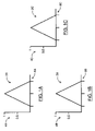
- FIGS. 6A and 6B illustrate two different kernels 610 and 620 , which may also be referred to as structuring elements, that can be utilized by alpha dilation module 14 .
- kernel 610 or 620 can be applied by placing its origin over each pixel of an image.
- the origins of kernels 610 and 620 are indicated as 612 and 622 , respectively.
- kernel 610 When kernel 610 is applied it takes into account pixels that are diagonally adjacent to the pixel at its origin.
- kernel 620 only takes into account the pixels that are horizontally or vertically adjacent to the pixel at its origin.
- FIG. 7A illustrates an exemplary binary image 710 that is 9 pixels wide and 9 pixels tall and contains binary alpha channels.
- Image 710 represents a binary image created by binary image creation module 12 according to steps 400 of FIG. 4 . Every pixel of image 710 having a 0 corresponds to a pixel of an overlay image pixel having a 0 alpha channel. Every pixel of image 710 having a 1 corresponds to a pixel of an overlay image pixel having a nonzero alpha channel.
- FIG. 7B illustrates the image 712 that results from the application of kernel 610 to image 710 of FIG. 7A by alpha dilation module 14 according to steps 500 of FIG. 5 .
- FIGS. 7C and 7D illustrate the same images as FIGS. 7A and 7B , except that each pixel with an alpha value of 1 is represented as a solid square instead of a 1 and each pixel with an alpha value of 0 is represented as an empty square instead of a 0.
- Image 720 of FIG. 7C corresponds to image 710 of FIG. 7A and image 722 of FIG. 7D corresponds to image 712 of FIG. 7B .
- FIG. 8 is a flowchart that illustrates the steps 800 taken by color dilation module 16 when determining which pixels of an overlay image require color dilation.
- the process begins at step ( 802 ).
- the binary alpha representation is subtracted from the dilated binary alpha representation to form a subtracted binary alpha representation.
- the binary image is subtracted from the dilated binary image to form a subtracted binary image. It is important to note that the term subtraction is not used in a strict mathematical sense.
- the binary alpha representation will contain a number of binary values, which may be represented as 0 and 1.
- the dilated binary alpha representation will contain all the 1's that the binary alpha representation contains plus any additional 1's that result from dilation.
- the subtracted binary alpha representation contains only the additional 1's that resulted from the dilation process.
- the original 1's have been removed by the subtraction process.
- subtraction as used herein refers to this removal regardless of how it is achieved. Therefore, even though they are referred to as being subtracted from one another, it is not necessary that the binary alpha representation and the dilated binary alpha representation be actual mathematical objects that are capable of being subtracted from one another.
- a pixel of the subtracted binary image is selected in any suitable manner. Preferably, a previously selected pixel is not selected again.
- step ( 808 ) it is determined whether the alpha channel of the pixel is equal to 1. If yes, then step ( 810 ) is executed. At step ( 810 ), the pixel is identified as a pixel requiring color dilation. If the answer reached at step ( 808 ) is no, then step ( 812 ) is executed in place of step ( 810 ). At step ( 812 ), the pixel is identified as a pixel not requiring dilation. Regardless of whether step ( 810 ) or ( 812 ) is executed, step ( 814 ) is executed next. At step ( 814 ) it is determined whether there are pixels that have not yet been examined. If not, then the process ends at step ( 816 ). If yes, then step ( 806 ) is repeated.
- FIGS. 9A , 9 B and 9 C illustrate three exemplary images 910 , 912 and 914 , respectively.
- Each of the binary images is 9 pixels wide and 11 pixels tall.
- the alpha channel is represented as either a 0 or 1.
- Binary image 910 is an image as created by binary image creation module 12 , according to steps 400 .
- Image 912 is the dilated binary image that results from dilating image 910 according to steps 500 taken by alpha dilation module 14 .
- Image 914 is the subtracted binary image that results from subtracting image 910 from image 912 as is done in step 804 of FIG. 8 .
- FIGS. 9D , 9 E and 9 F illustrate three exemplary images 920 , 922 and 924 , respectively. Each of these images corresponds to an image illustrated in FIG. 9A , 9 B or 9 C.
- Image 920 corresponds to image 910
- image 922 corresponds to image 912
- image 924 corresponds to image 914 .
- a pixel with an alpha channel of 0 is represented as an empty square and a pixel with an alpha channel of 1 is represented as a solid square.
- FIGS. 9D , 9 E and 9 F are included in order to illustrate the effects of dilation and binary subtraction more clearly.
- FIG. 10 is a flowchart that illustrates the steps taken by color dilation module 16 according to one method of dilating the colors of the pixels.
- the process begins at step ( 1002 ).
- a pixel of the overlay image is selected in any suitable manner from the set of pixels that were identified at step ( 810 ) of FIG. 8 or step ( 312 ) of FIG. 3 .
- a previously selected pixel is not selected again.
- all pixels in the neighborhood are examined and their color channels are identified. In one embodiment, pixels with an alpha channel of 0 are ignored.
- the size of the neighborhood is determined in part by the scaling algorithm used by scaling module 18 . For example, if bilinear scaling is used then the neighborhood comprises only the immediate neighbors. However, for other scaling algorithms, such as bicubic scaling, the neighborhood may be larger.
- step ( 1008 ) it is determined whether the color channels of all the pixels in the neighborhood are the same. If yes, then step ( 1010 ) is executed. At step ( 1010 ), the color settings of the pixel are set to be the same as that of its neighbors. However, if the answer reached at step ( 1008 ) is no, then step ( 1012 ) is executed. At step ( 1012 ), the color channels of the neighbors are averaged and the color channels of the selected pixels are set to the average.
- the averaging may be performed by any suitable means. For example, in an embodiment in which the original images already have binary alpha values and where only the 8 neighboring pixels are used, the averaging step can be achieved by a simple average.
- the averaging may be accomplished by a weighted average.
- the weights can be determined by a number of factors including the alpha value at the pixel, the proximity of the pixel, and the position of the pixel. As an example of where the position may be used to affect the weighting, if a 3 ⁇ 3 kernel is used, then the corner pixels may be given less weight than the pixels that are horizontally or vertically adjacent. Similarly, an example of where the proximity may be used to affect the weighting is in a 5 ⁇ 5 kernel the pixels that are immediately horizontally or vertically adjacent may be given greater weight than the pixels that are two pixels away in the horizontal or vertical direction.
- the color of the pixel is calculated according to the following Equation:
- C average is the vector of the color channels of the pixel that was dilated into
- C i and A i are the color and alpha channels of the neighboring pixels
- n is the number of neighboring pixels that are used by the equation.
- the pixels diagonally adjacent may be given less weight than those that are immediately horizontally or vertically adjacent.
- the color of the pixel is calculated according to the following equation:
- C(x,y) average is the output color value at the column and row pixel position (x,y) in the overlay image.
- C(a,b) and A(a,b) are the input overlay color values and alpha values respectively, at overlay pixel (a,b).
- Equation (3) is a vector equation and each color channel is calculated in the same manner.
- K(i,j) are the kernel weights used for averaging the colors.
- the kernel is a 3 ⁇ 3 kernel and therefore the i and j values range from ⁇ 1 to +1.
- the kernel may be of a different size and the i and j values would vary appropriately.
- the above equation is meant to be exemplary only.
- the actual method used to determine the color of the pixel that is dilated into may be determined according to the particular implementation utilized.
- One of the above-described methods may be more efficient than the other in one implementation, but may be less efficient in a second implementation.
- knowledge of the particular implementation is helpful in determining which method to use.
- step ( 1014 ) is executed next.
- step ( 1014 ) it is determined whether there are pixels that have not yet been examined. If not, then the process ends at step ( 1016 ). If yes, then step ( 1004 ) is repeated. It is important to note that color dilation module 16 does not affect the alpha channels of the overlay image; only the color channels of the overlay image are affected by color dilation module 16 during steps 1000 .
- FIG. 11 is a flowchart illustrating the steps 1100 by which overlay combining module 22 of FIG. 2A combines multiple overlays.
- the process beings at step ( 1102 ).
- the bottom two overlays are selected.
- the two selected overlays are combined. For any regions of the overlay images that intersect, the resulting colour and alpha channels of each pixel can be determined according to the following equation:
- pixels with undefined color values may result from this step of combining overlay images. Such pixels are essentially outside the boundaries of the overlay and in the embodiments of system 10 presented herein do not require any separate calculation.
- the color values may be set to a default color such as C lower or black.
- these pixels are not part of the overlay before scaling they affect the image that results from the scaling process. For this reason, if the color values of these pixels were set to default colors in the prior art techniques, then many of the artifacts discussed above could result from the scaling process.
- the steps associated with the dilation of the color channels replace the relevant default colors with dilated colors and thereby prevent the occurrence of the above-mentioned artifacts.
- FIG. 12A illustrates the color channel portion of an overlay image 1200 .
- the color portion of the overlay image 1200 comprises a strip of uniform color 1210 .
- FIG. 12B illustrates the alpha channel portion of the overlay image 1200 of FIG. 12A .
- the alpha channel portion comprises a strip of uniform alpha values 1220 in the same position as the strip of color 1210 .
- strip 1210 represents the color channels of a set of pixels in overlay image 1200
- strip 1220 represents the alpha channels of the same set of pixels.
- FIGS. 13A and 13B are similar to FIGS. 12A and 12B except that they are for a different overlay image.
- FIGS. 14A and 14B respectively illustrate the color channels and the alpha channels of an image 1400 formed by combining overlay images 1200 and 1300 .
- Equation (5) which is given above, could be used to calculate the color values for square 1422 .
- Equation (4) could be used to calculate the alpha values 1424 .
- the alpha channels of the overlay images may be binary, as they are in some medical imaging technology such as IMPAX® and other Picture Archive and Communication Systems (PACS).
- PACS Picture Archive and Communication Systems
- the color channel of the composite is more easily determined, as each pixel of each layer is either fully opaque or fully transparent.
Abstract
Description
C out =C overlay *A overlay +C image*(1−A overlay) (1)
wherein Cout represents the normalized color channels of the resulting image, Coverlay represents the color channels of the overlay image, Cimage represents the color channels of the background image, Aoverlay represents the alpha value of the overlay image. Each of the Cout, Coverlay, and Cimage are in fact vectors containing each of the color channels of the particular pixel. For example, Cout=(Rout, Gout, Bout). The above-described process by which the color channels are combined may be referred to as alpha blending.
-
- (a) identifying a set of pixels of the composite overlay image as pixels to be dilated;
- (b) dilating the color channels of the identified pixels to form a dilated composite overlay image; and
- (c) scaling the dilated composite overlay image.
-
- (a) a memory for storing the pixels associated with the overlay images;
- (b) a processor coupled to the memory for:
- (i) identifying a set of pixels of the composite overlay image as pixels to be dilated;
- (ii) dilating the color channels of the identified pixels to form a dilated composite overlay image; and
- (iii) scaling the dilated composite overlay image.
where Caverage is the vector of the color channels of the pixel that was dilated into, Ci and Ai are the color and alpha channels of the neighboring pixels, and n is the number of neighboring pixels that are used by the equation. In the exemplary embodiment the eight neighboring pixels are used and therefore n=8. As mentioned above, in an alternative embodiment the pixels diagonally adjacent may be given less weight than those that are immediately horizontally or vertically adjacent. In such an embodiment, the color of the pixel is calculated according to the following equation:
where C(x,y)average is the output color value at the column and row pixel position (x,y) in the overlay image. C(a,b) and A(a,b) are the input overlay color values and alpha values respectively, at overlay pixel (a,b). Equation (3) is a vector equation and each color channel is calculated in the same manner.
| ColorTotal = {0,0,0} | ||
| NumAlphas = 0 | ||
| For each n | ||
| { | ||
| if Alphan != 0 | ||
| { | ||
| C_average += Colorn | ||
| NumAlphas += 1 | ||
| } | ||
| } | ||
| C_average = ColorTotal / NumAlphas | ||
wherein Acomposite is the resulting alpha channel, Aupper is the alpha channel of the upper overlay, Alower is the alpha channel of the bottom overlay, Ccomposite is the vector of the resulting color channels, Cupper is the vector of the color channels of the upper overlay, and Clower is the vector of the color channels of the lower overlay. Note that Equation (5) is only valid for non-zero values of Acomposite. If Acomposite is zero then the color values at this pixel are not well defined. Thus, pixels with undefined color values may result from this step of combining overlay images. Such pixels are essentially outside the boundaries of the overlay and in the embodiments of
Claims (23)
Priority Applications (3)
| Application Number | Priority Date | Filing Date | Title |
|---|---|---|---|
| US11/474,342 US8072472B2 (en) | 2006-06-26 | 2006-06-26 | System and method for scaling overlay images |
| PCT/EP2007/056053 WO2008000652A1 (en) | 2006-06-26 | 2007-06-19 | System and method for scaling overlay images |
| EP07765482A EP2041718A1 (en) | 2006-06-26 | 2007-06-19 | System and method for scaling overlay images |
Applications Claiming Priority (1)
| Application Number | Priority Date | Filing Date | Title |
|---|---|---|---|
| US11/474,342 US8072472B2 (en) | 2006-06-26 | 2006-06-26 | System and method for scaling overlay images |
Publications (2)
| Publication Number | Publication Date |
|---|---|
| US20070296736A1 US20070296736A1 (en) | 2007-12-27 |
| US8072472B2 true US8072472B2 (en) | 2011-12-06 |
Family
ID=38421441
Family Applications (1)
| Application Number | Title | Priority Date | Filing Date |
|---|---|---|---|
| US11/474,342 Active US8072472B2 (en) | 2006-06-26 | 2006-06-26 | System and method for scaling overlay images |
Country Status (3)
| Country | Link |
|---|---|
| US (1) | US8072472B2 (en) |
| EP (1) | EP2041718A1 (en) |
| WO (1) | WO2008000652A1 (en) |
Cited By (2)
| Publication number | Priority date | Publication date | Assignee | Title |
|---|---|---|---|---|
| US20110267364A1 (en) * | 2009-08-20 | 2011-11-03 | Clarion Co., Ltd. | In-vehicle device |
| US20120170061A1 (en) * | 2007-10-31 | 2012-07-05 | Canon Kabushiki Kaisha | Image processor and image processing method |
Families Citing this family (6)
| Publication number | Priority date | Publication date | Assignee | Title |
|---|---|---|---|---|
| US20080117333A1 (en) * | 2006-11-17 | 2008-05-22 | Disney Enterprises, Inc. | Method, System And Computer Program Product For Video Insertion |
| US9380300B1 (en) * | 2013-10-31 | 2016-06-28 | Crimson Corporation | Encoding location information in alpha channels for HTML remote control |
| JP6234234B2 (en) * | 2014-01-14 | 2017-11-22 | キヤノン株式会社 | Information processing apparatus, information processing method, and program |
| US10430987B1 (en) * | 2017-06-09 | 2019-10-01 | Snap Inc. | Annotating an image with a texture fill |
| US10855755B2 (en) * | 2018-05-04 | 2020-12-01 | Citrix Systems, Inc. | WebRTC API redirection with fallbacks |
| CN112581588A (en) * | 2020-12-23 | 2021-03-30 | 广东三维家信息科技有限公司 | Wallboard spray painting method and device and computer storage medium |
Citations (21)
| Publication number | Priority date | Publication date | Assignee | Title |
|---|---|---|---|---|
| US4954970A (en) | 1988-04-08 | 1990-09-04 | Walker James T | Video overlay image processing apparatus |
| US5182728A (en) | 1991-06-28 | 1993-01-26 | Acoustic Imaging Technologies Corporation | Ultrasound imaging system and method |
| US5920659A (en) * | 1996-06-24 | 1999-07-06 | Intel Corporation | Method and apparatus for scaling image data having associated transparency data |
| US6128041A (en) * | 1997-07-11 | 2000-10-03 | Daewoo Electronics Co., Ltd. | Method and apparatus for binary shape encoding |
| US6172717B1 (en) * | 1997-07-31 | 2001-01-09 | Sony Corporation | Apparatus and methods for synthesizing foreground and background images |
| US6208351B1 (en) * | 1997-12-22 | 2001-03-27 | Adobe Systems Incorporated | Conversion of alpha-multiplied color data |
| US6304245B1 (en) * | 1997-09-30 | 2001-10-16 | U.S. Philips Corporation | Method for mixing pictures |
| US20030001973A1 (en) * | 2001-06-29 | 2003-01-02 | Roever Jens A. | Color key preservation during sample rate conversion |
| US20030043390A1 (en) * | 2001-08-29 | 2003-03-06 | Fritz Terry M. | Systems and methods for applying 8-bit alpha blending to bitonal images |
| US20030223662A1 (en) * | 2002-05-30 | 2003-12-04 | Chin-Hung Chang | Bearing assembly |
| WO2004039938A2 (en) | 2002-10-31 | 2004-05-13 | Oridis Biomed Forschungs- Und Entwicklungs Gmbh | Method and device for manipulating samples |
| US20040169664A1 (en) | 2001-09-06 | 2004-09-02 | Hoffman Michael T. | Method and apparatus for applying alterations selected from a set of alterations to a background scene |
| US20050068336A1 (en) | 2003-09-26 | 2005-03-31 | Phil Van Dyke | Image overlay apparatus and method for operating the same |
| US20050093890A1 (en) * | 2003-06-12 | 2005-05-05 | Microsoft Corporation | System and method for displaying images utilizing multi-blending |
| US20050117789A1 (en) * | 2003-11-21 | 2005-06-02 | Samsung Electronics Co., Ltd. | Apparatus and method for generating coded block pattern for alpha channel image and alpha channel image encoding/decoding apparatus and method using the same |
| US6903751B2 (en) * | 2002-03-22 | 2005-06-07 | Xerox Corporation | System and method for editing electronic images |
| US20050206652A1 (en) * | 2004-03-17 | 2005-09-22 | Atousa Soroushi | Memory efficient method and apparatus for displaying large overlaid camera images |
| US7050070B2 (en) * | 2002-07-05 | 2006-05-23 | Kabushiki Kaisha Toshiba | Image editing method and image editing apparatus |
| US20060159360A1 (en) * | 2004-12-20 | 2006-07-20 | Michael Vaz | Method and apparatus for efficient computation of morphology operations |
| US20070140559A1 (en) * | 2005-12-15 | 2007-06-21 | Microsoft Corporation | Compressing images in documents |
| US20090028432A1 (en) * | 2005-12-30 | 2009-01-29 | Luca Rossato | Segmentation of Video Sequences |
-
2006
- 2006-06-26 US US11/474,342 patent/US8072472B2/en active Active
-
2007
- 2007-06-19 WO PCT/EP2007/056053 patent/WO2008000652A1/en active Application Filing
- 2007-06-19 EP EP07765482A patent/EP2041718A1/en not_active Withdrawn
Patent Citations (22)
| Publication number | Priority date | Publication date | Assignee | Title |
|---|---|---|---|---|
| US4954970A (en) | 1988-04-08 | 1990-09-04 | Walker James T | Video overlay image processing apparatus |
| US5182728A (en) | 1991-06-28 | 1993-01-26 | Acoustic Imaging Technologies Corporation | Ultrasound imaging system and method |
| US5920659A (en) * | 1996-06-24 | 1999-07-06 | Intel Corporation | Method and apparatus for scaling image data having associated transparency data |
| US6128041A (en) * | 1997-07-11 | 2000-10-03 | Daewoo Electronics Co., Ltd. | Method and apparatus for binary shape encoding |
| US6172717B1 (en) * | 1997-07-31 | 2001-01-09 | Sony Corporation | Apparatus and methods for synthesizing foreground and background images |
| US6304245B1 (en) * | 1997-09-30 | 2001-10-16 | U.S. Philips Corporation | Method for mixing pictures |
| US6208351B1 (en) * | 1997-12-22 | 2001-03-27 | Adobe Systems Incorporated | Conversion of alpha-multiplied color data |
| US20030001973A1 (en) * | 2001-06-29 | 2003-01-02 | Roever Jens A. | Color key preservation during sample rate conversion |
| US20030043390A1 (en) * | 2001-08-29 | 2003-03-06 | Fritz Terry M. | Systems and methods for applying 8-bit alpha blending to bitonal images |
| US20040169664A1 (en) | 2001-09-06 | 2004-09-02 | Hoffman Michael T. | Method and apparatus for applying alterations selected from a set of alterations to a background scene |
| US6903751B2 (en) * | 2002-03-22 | 2005-06-07 | Xerox Corporation | System and method for editing electronic images |
| US20030223662A1 (en) * | 2002-05-30 | 2003-12-04 | Chin-Hung Chang | Bearing assembly |
| US7050070B2 (en) * | 2002-07-05 | 2006-05-23 | Kabushiki Kaisha Toshiba | Image editing method and image editing apparatus |
| US20060176319A1 (en) * | 2002-07-05 | 2006-08-10 | Takashi Ida | Image editing method and image editing apparatus |
| WO2004039938A2 (en) | 2002-10-31 | 2004-05-13 | Oridis Biomed Forschungs- Und Entwicklungs Gmbh | Method and device for manipulating samples |
| US20050093890A1 (en) * | 2003-06-12 | 2005-05-05 | Microsoft Corporation | System and method for displaying images utilizing multi-blending |
| US20050068336A1 (en) | 2003-09-26 | 2005-03-31 | Phil Van Dyke | Image overlay apparatus and method for operating the same |
| US20050117789A1 (en) * | 2003-11-21 | 2005-06-02 | Samsung Electronics Co., Ltd. | Apparatus and method for generating coded block pattern for alpha channel image and alpha channel image encoding/decoding apparatus and method using the same |
| US20050206652A1 (en) * | 2004-03-17 | 2005-09-22 | Atousa Soroushi | Memory efficient method and apparatus for displaying large overlaid camera images |
| US20060159360A1 (en) * | 2004-12-20 | 2006-07-20 | Michael Vaz | Method and apparatus for efficient computation of morphology operations |
| US20070140559A1 (en) * | 2005-12-15 | 2007-06-21 | Microsoft Corporation | Compressing images in documents |
| US20090028432A1 (en) * | 2005-12-30 | 2009-01-29 | Luca Rossato | Segmentation of Video Sequences |
Non-Patent Citations (5)
| Title |
|---|
| Fisher, et al., "Dilation", http://www.cee.hw.ac.uk/hipr/html/dilate.html, Hypermedia Image Processing Reference, Department of Artificial Intelligence, University of Edinburgh, U.K., 1994. |
| Harley R. Maler, Arthur R. Weeks, "The Pocket Handbook of Image Processing Algorithms in C", 1993, Prentice Hall Ptr, Upper Saddle River, New Jersey 07458, pp. 178-179, 252-253, 268-269. |
| Image Processing Fundamentals, "Morphology-Based Operations", http://www.ph.tn.tudelft.nl/Courses/FIP/noframes/fip-Morpholo.html, 2003. |
| Optimizing Image Processing With Image, "What are Morphological Operations?", http://www.gemma.apple.com/documentation/Performance/Conceptual, 2005. |
| PCT International Search Report/ Written Opinion mailed on Sep. 7, 2007. |
Cited By (4)
| Publication number | Priority date | Publication date | Assignee | Title |
|---|---|---|---|---|
| US20120170061A1 (en) * | 2007-10-31 | 2012-07-05 | Canon Kabushiki Kaisha | Image processor and image processing method |
| US8830546B2 (en) * | 2007-10-31 | 2014-09-09 | Canon Kabushiki Kaisha | Apparatus and method determining whether object specified to enable an underlying object to be seen there through is included in data to be printed, and medium having instructions for performing the method |
| US20110267364A1 (en) * | 2009-08-20 | 2011-11-03 | Clarion Co., Ltd. | In-vehicle device |
| US8564610B2 (en) * | 2009-08-20 | 2013-10-22 | Clarion Co., Ltd. | In-vehicle device |
Also Published As
| Publication number | Publication date |
|---|---|
| WO2008000652A1 (en) | 2008-01-03 |
| EP2041718A1 (en) | 2009-04-01 |
| US20070296736A1 (en) | 2007-12-27 |
Similar Documents
| Publication | Publication Date | Title |
|---|---|---|
| US8072472B2 (en) | System and method for scaling overlay images | |
| US7945114B2 (en) | Image transform method for obtaining expanded image data, image processing apparatus and image display device therefore | |
| CN100389597C (en) | Methods and systems for locally adaptive image processing filters | |
| US9832388B2 (en) | Deinterleaving interleaved high dynamic range image by using YUV interpolation | |
| US7613363B2 (en) | Image superresolution through edge extraction and contrast enhancement | |
| US7965305B2 (en) | Color display system with improved apparent resolution | |
| KR101634197B1 (en) | Gamut mapping which takes into account pixels in adjacent areas of a display unit | |
| CN101360250B (en) | Immersion method and system, factor dominating method, content analysis method and parameter prediction method | |
| US8290252B2 (en) | Image-based backgrounds for images | |
| KR100772906B1 (en) | Method and apparatus for displaying image signal | |
| JP2003036048A (en) | Display device, display method, and recording medium in which display control program is recorded | |
| US9449373B2 (en) | Modifying appearance of lines on a display system | |
| CN101248443B (en) | Image processing using saltating samples | |
| US11854157B2 (en) | Edge-aware upscaling for improved screen content quality | |
| JPH06510133A (en) | Display device for anti-aliased images | |
| TWI542189B (en) | Image display apparatus, method of driving image display apparatus, grayscale conversion conputer program product, and grayscale conversion apparatus | |
| EP0855682B1 (en) | Scan line rendering of convolutions | |
| US9928577B2 (en) | Image correction apparatus and image correction method | |
| US9911399B2 (en) | Method of image processing, image processor performing the method and display device having the image processor | |
| US9754162B2 (en) | Image processing method and device for adaptive image enhancement | |
| CN113139921A (en) | Image processing method, display device, electronic apparatus, and storage medium | |
| JP4084105B2 (en) | Character creation method and character creation program | |
| JP4265363B2 (en) | Image processing device | |
| JPH08272351A (en) | Picture processor |
Legal Events
| Date | Code | Title | Description |
|---|---|---|---|
| AS | Assignment |
Owner name: AGFA INC., CANADA Free format text: ASSIGNMENT OF ASSIGNORS INTEREST;ASSIGNOR:HUNT, NEIL EDMUND JAMES;REEL/FRAME:018033/0658 Effective date: 20060622 |
|
| AS | Assignment |
Owner name: AGFA HEALTHCARE INC., CANADA Free format text: ASSIGNMENT OF ASSIGNORS INTEREST;ASSIGNOR:AGFA INC.;REEL/FRAME:022547/0168 Effective date: 20081210 |
|
| FEPP | Fee payment procedure |
Free format text: PAYOR NUMBER ASSIGNED (ORIGINAL EVENT CODE: ASPN); ENTITY STATUS OF PATENT OWNER: LARGE ENTITY |
|
| STCF | Information on status: patent grant |
Free format text: PATENTED CASE |
|
| FPAY | Fee payment |
Year of fee payment: 4 |
|
| MAFP | Maintenance fee payment |
Free format text: PAYMENT OF MAINTENANCE FEE, 8TH YEAR, LARGE ENTITY (ORIGINAL EVENT CODE: M1552); ENTITY STATUS OF PATENT OWNER: LARGE ENTITY Year of fee payment: 8 |
|
| MAFP | Maintenance fee payment |
Free format text: PAYMENT OF MAINTENANCE FEE, 12TH YEAR, LARGE ENTITY (ORIGINAL EVENT CODE: M1553); ENTITY STATUS OF PATENT OWNER: LARGE ENTITY Year of fee payment: 12 |