US8070459B2 - Pressure control method - Google Patents
Pressure control method Download PDFInfo
- Publication number
- US8070459B2 US8070459B2 US10/586,200 US58620005A US8070459B2 US 8070459 B2 US8070459 B2 US 8070459B2 US 58620005 A US58620005 A US 58620005A US 8070459 B2 US8070459 B2 US 8070459B2
- Authority
- US
- United States
- Prior art keywords
- pump
- pressure
- chamber
- flow
- valve
- Prior art date
- Legal status (The legal status is an assumption and is not a legal conclusion. Google has not performed a legal analysis and makes no representation as to the accuracy of the status listed.)
- Expired - Fee Related, expires
Links
Images


Classifications
-
- G—PHYSICS
- G05—CONTROLLING; REGULATING
- G05D—SYSTEMS FOR CONTROLLING OR REGULATING NON-ELECTRIC VARIABLES
- G05D16/00—Control of fluid pressure
- G05D16/20—Control of fluid pressure characterised by the use of electric means
- G05D16/2006—Control of fluid pressure characterised by the use of electric means with direct action of electric energy on controlling means
- G05D16/208—Control of fluid pressure characterised by the use of electric means with direct action of electric energy on controlling means using a combination of controlling means as defined in G05D16/2013 and G05D16/2066
Definitions
- the present invention relates to a pressure control method, particularly, although not exclusively, for a vacuum chamber of a semiconductor or a flat panel display manufacturing assembly.
- FIG. 1 shows a vacuum system having a chamber 12 , with volume V 0 , and a pressure control system 10 for controlling the pressure in the chamber.
- a vacuum pump 14 having a pumping speed S pump is connected to a chamber outlet 16 via a duct 18 for evacuating gas from chamber 12 .
- a valve 20 with variable conductance C valve controls gas flow from chamber 12 to pump 14 .
- Valve 20 is usually a throttle valve, as shown, having a moveable vane for changing C valve .
- a pressure gauge 22 monitors the pressure P in chamber 12 and a pressure control unit 24 controls C valve according to the monitored pressure P.
- the flow of process gas at a mass flow rate Q in into chamber 12 is controlled by mass flow controller 26 .
- Process gas is evacuated from chamber 12 at a mass flow rate Q out , which is determined by the product of the pressure in the chamber and the effective pumping speed S eff .
- the effective pumping speed is:
- pump 14 evacuates chamber 12 to a predetermined low pressure and pressure control system 10 incrementally increases the pressure in chamber 12 to allow each processing step to be performed at its required pressure.
- Pressure change occurs according to:
- the time taken for a pressure increase to occur depends on the time it takes for valve 20 to change to a predetermined conductance; and the rate of pressure increase for a fixed valve position and process gas mass flow rate (i.e. the time taken for the pressure to increase once the valve has been changed to the predetermined conductance).
- the first factor is dependent on the specific design of the valve and is typically very low (less than two seconds).
- the second factor is dependent on the mass flow rate into the system (Q in ), the mass flow rate of the system (Q out ) and the volume of the chamber V 0 .
- the valve is set to a preset position so that C valve is decreased from 850 m 3 /hour to 50 m 3 /hour. Consequently, pressure P increases from 0.1 mbar to 2.5 mbar.
- V 0 is relatively small and Q in is relatively high, and therefore pressure response time is limited by the response time of the valve. Accordingly, the pressure in the chamber reaches the required pressure of 2.5 mbar after 2 seconds i.e. the time taken for the valve 20 to reach its preset position.
- FIG. 3 shows pressure increase for a system where V 0 is 100 litres and Q in is 2 standard litres per minute. It will be seen that valve 20 reaches its preset position after about two seconds, but pressure P does not reach the required pressure until about 35 seconds.
- the present invention provides a method of setting the pressure in a chamber of a vacuum system to a required pressure, the system comprising a pressure control system including a pump for evacuating gas from the chamber and a flow controller for allowing the flow of gas into the chamber, the method comprising setting an initial flow out of the chamber for achieving a pressure above the required pressure so as to increase the rate of pressure increase, the initial flow occurring over a transient period which does not allow the pressure to exceed the required pressure, and setting a preset flow out of the chamber after the transient period has elapsed for achieving and maintaining the required pressure.
- FIG. 1 shows a typical vacuum system
- FIG. 2 is a graph showing chamber pressure and C valve , against time, for a prior art pressure control method
- FIG. 3 is another graph showing chamber pressure and C valve , against time, for a prior art pressure control method
- FIG. 4 is a graph showing chamber pressure and C valve , against time, for a pressure control method according to a first embodiment of the present invention
- FIG. 5 is a graph showing chamber pressure and C valve , against time, for a pressure control method according to a variation of the first embodiment
- FIGS. 6 and 7 show two variations of the vacuum system shown in FIG. 1 ;
- FIG. 8 shows a vacuum system for use with a method according to a second embodiment of the present invention
- FIG. 9 is a graph showing chamber pressure and gas flow into the chamber, against time, for a pressure control method according to the second embodiment of the present invention.
- FIG. 10 shows a variation of the method shown in FIG. 9 ;
- FIG. 11 shows a vacuum system for use with a method according to a third embodiment of the present invention.
- FIGS. 12 to 15 show variations of vacuum systems for use with the methods of the first to third embodiments
- FIG. 16 shows a vacuum system for use with a method according to a fourth embodiment of the present invention.
- FIGS. 17 and 18 show variations of the vacuum system shown in FIG. 16 .
- the rate of pressure increase in a chamber of a vacuum system is:
- V 0 is constant for any given vacuum system and the difference between the flow of gas into and out of the chamber controls the build up of gas in the chamber and hence the rate of pressure increase.
- the flow of gas out of the chamber (Q out ) is controlled by changing the valve conductance.
- the valve conductance When an increase in pressure is required the valve conductance is set to the predetermined conductance and the pressure is allowed to increase gradually and to stabilise at the required pressure (see FIG. 3 ).
- an initial flow into (Q in ) and/or out (Q out ) of the chamber 12 is set to achieve a pressure above the required pressure so as to increase the rate of pressure increase. The initial flow occurs over a transient period and is selected so that the pressure does not exceed the required pressure.
- the initial flow is reduced to the predetermined flow when the required pressure is attained, to stabilise the chamber at the required pressure.
- the initial flow can be reduced to the predetermined flow before the required pressure is attained, and although the pressure increase would not be as quick as the preferred method, it would still be faster than the prior art method.
- the valve is set to a preset conductance of 50 m 3 /hour.
- a valve conductance gradually increases the pressure in the prior art to a required pressure of 2.5 mbar after about 35 seconds, as shown by the prior art response curve superimposed on the graph.
- C valve is reduced to an initial conductance which is well below the preset conductance for controlling the required pressure. Accordingly, the flow out (Q out ) is set below the predetermined flow out for the required pressure for a transient period of approximately six and a half seconds. Accordingly, the pressure increases to 2.5 mbar after only about 8 seconds.
- the length of the transient period is calculated according to the difference between the required pressure and the current pressure, the rate of pressure increase achieved by the initial valve conductance, and the speed of the valve.
- the pressure control unit controls C valve to compensate for fluctuations in pressure and to maintain the chamber at the required pressure.
- the embodiment provides an improvement of about 27 seconds.
- C valve is reduced to an initial conductance of 10 m 3 /hour for a fixed time.
- the fixed time is slightly shorter than the transient period because the valve takes a finite time to move between positions i.e. from a conductance of 50 m 3 /hour to 10 m 3 /hour and back to 50 m 3 /hour.
- FIG. 5 which illustrates a variation of the embodiment.
- the preset C valve is 57 m 3 /hour for achieving a required pressure of 7.5 mbar.
- C valve is reduced below 57 m 3 /hour to 0 m 3 /hour and immediately increased to 57 m 3 /hour.
- FIG. 5 shows C valve being reduced to a conductance of 0 m 3 /hour (valve fully closed) for increasing the rate of pressure increase.
- a reduction to 0 m 3 /hour decreases Q out to zero and therefore the rate of pressure increase is the maximum for this method and becomes:
- valve 20 is positioned down-stream of pump 14 and is operable for controlling the effective pumping speed and hence the pressure in chamber 12 .
- the pump is shown having a high vacuum pump 15 and a backing pump 17 , and the valve 20 is positioned between the two pumps and is operable for controlling the effective pumping speed.
- FIGS. 8 to 10 A second embodiment will now be described with reference to FIGS. 8 to 10 .
- FIG. 8 shows a vacuum system of a similar arrangement to that shown in FIG. 1 .
- FIG. 8 shows a connection 28 between pressure control unit 24 and mass flow controller 26 .
- An increased rate of pressure increase is achieved by an increase in the mass flow of process gas (Q in ) into the chamber 12 for a transient period over and above the mass flow of process gas required for processing.
- the increase in Q in increases the differential flow (Q in ⁇ Q out ) above the predetermined differential flow for the required pressure.
- valve 20 is set to the predetermined position for a required pressure of 3.5 mbar.
- the process gas mass flow rate (Q in ) required for processing is two standard litres per minute (slpm).
- Q in is increased above two slpm for a transient period of about 5 seconds to increase the rate at which pressure increases over the rate at which pressure increases in the prior art as shown by the line superimposed in FIG. 9 .
- the length of the transient period is calculated according to the difference between the required pressure and the current pressure, the rate of pressure increase achieved by the initial flow, and the speed of the mass flow controller.
- Q in is reduced to two slpm to coincide with the pressure in chamber 12 reaching the required pressure.
- Q in is increased to 20 slpm where it is maintained for a period just shorter than the transient period to allow a finite time for the mass flow rate to increase from and decrease to two slpm.
- Q in is increased to a mass flow rate of 100 slpm and then immediately reduced to 2 slpm. It should be noted however that it is advantageous to maintain Q in at a steady state for a fixed time to ensure better control.
- FIG. 11 A third embodiment is shown in FIG. 11 , which differs from the arrangement in FIG. 1 in that a connection 30 connects pressure control unit 24 to purge mass flow controller 32 .
- An increased rate of pressure increase is achieved by supplying purge gas (Q in 2 ) into duct 18 upstream of valve 20 so that the purge gas increases the pressure in chamber 12 .
- Purge gas is supplied for a transient period thereby increasing the differential flow rate ((Q in +Q in 2 ) ⁇ Q out ) above the predetermined differential flow rate for maintaining the required pressure for processing.
- the supply of purge gas achieves similar results to those described with reference to FIGS. 9 and 10 .
- FIGS. 12 to 15 show a very quick increase in pressure is required or if chamber 12 is very large or the mass flow rate for processing is very small.
- FIGS. 12 to 15 Four examples showing vacuum systems are shown in FIGS. 12 to 15 .
- FIG. 12 differs from FIG. 11 in that valve 20 is downstream of pump 14 .
- purge gas flow controller 32 is arranged to introduce gas directly into the pump 14 .
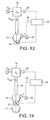
- FIG. 14 shows an arrangement similar to FIG. 7 showing two pumps 15 , 17 .
- the purge gas flow controller 32 is arranged to introduce gas directly into the pump 15 , and valve 20 is positioned between the two pumps.
- purge gas flow controller 32 is arranged to introduce gas upstream of high vacuum pump 15 .
- FIG. 16 A fourth embodiment is shown in FIG. 16 , which differs from the arrangement shown in FIG. 1 in that a connection 34 is made between pressure control unit 24 and a pump inverter 36 .
- Connection 34 enables the pressure control unit 24 to control the rotational speed of the pump 14 and hence the pumping speed (S pump ).
- Valve 20 is omitted from the arrangement.
- a decrease in S pump decreases the effective pumping speed and therefore increases the rate of pressure increase.
- decreasing the rotational speed of the pump 14 increases the mass flow rate of gas leaked upstream across the pump (Q leak ). Accordingly, the differential flow rate ((Q in +Q leak ) ⁇ Q out ) is further increased.
- the embodiment shown in FIG. 16 therefore, constitutes a combination of the valve conductance embodiment and the variable inlet gas flow embodiments.
- the pumping speed S pump is decreased for a transient period below a predetermined pumping speed for achieving and maintaining a required chamber pressure.
- S pump can be decreased below the predetermined pumping speed to an initial preset where it is maintained for a period and then increased to the predetermined pumping speed.
- S pump can be decreased to a pumping speed and then immediately increased to the predetermined pumping speed. It should be noted however that it is advantageous to maintain pumping speed at a steady state for a fixed time to ensure better control.
- S pump is increased to the predetermined pumping speed before, or to coincide with, chamber pressure reaching the required pressure. Once the required chamber pressure has been achieved, pressure control unit 24 monitors chamber pressure P and adjusts pumping speed to compensate for pressure fluctuations.
- the fourth embodiment can be used in combination with either or both of the embodiments described with reference to FIGS. 9 and 10 , or the embodiment described with reference to FIGS. 4 and 5 .
- FIGS. 17 and 18 Variations of the fourth embodiment are shown in FIGS. 17 and 18 .
- two inverters are operable for controlling two pumps 15 and 17 .
- a single inverter is operable for controlling the downstream pump 17 only.
- a method for setting the pressure in a chamber of a vacuum system to a required pressure, the system comprising a pressure control system including a pump for evacuating gas from the chamber and a flow controller for allowing the flow of gas into the chamber.
- the method comprises setting an initial flow into and/or out of the chamber for achieving a pressure above the required pressure so as to increase the rate of pressure increase, the initial flow occurring over a transient period which does not allow the pressure to exceed the required pressure, and setting a preset flow into and/or out of the chamber after the transient period has elapsed for achieving and maintaining the required pressure.
Abstract
Description
where Csystem is the conductance of the vacuum system upstream of the valve.
Claims (21)
Applications Claiming Priority (3)
| Application Number | Priority Date | Filing Date | Title |
|---|---|---|---|
| GB0401396.7 | 2004-01-22 | ||
| GBGB0401396.7A GB0401396D0 (en) | 2004-01-22 | 2004-01-22 | Pressure control method |
| PCT/GB2005/000124 WO2005071509A1 (en) | 2004-01-22 | 2005-01-14 | Pressure control method |
Publications (2)
| Publication Number | Publication Date |
|---|---|
| US20070163330A1 US20070163330A1 (en) | 2007-07-19 |
| US8070459B2 true US8070459B2 (en) | 2011-12-06 |
Family
ID=31971282
Family Applications (1)
| Application Number | Title | Priority Date | Filing Date |
|---|---|---|---|
| US10/586,200 Expired - Fee Related US8070459B2 (en) | 2004-01-22 | 2005-01-14 | Pressure control method |
Country Status (8)
| Country | Link |
|---|---|
| US (1) | US8070459B2 (en) |
| EP (1) | EP1706803B1 (en) |
| JP (1) | JP2007519112A (en) |
| AT (1) | ATE419573T1 (en) |
| DE (1) | DE602005012050D1 (en) |
| GB (1) | GB0401396D0 (en) |
| TW (1) | TWI358620B (en) |
| WO (1) | WO2005071509A1 (en) |
Cited By (5)
| Publication number | Priority date | Publication date | Assignee | Title |
|---|---|---|---|---|
| US20100076658A1 (en) * | 2008-09-23 | 2010-03-25 | Shih-Chieh Liao | Method for controlling constant-pressure fluid |
| US20120063917A1 (en) * | 2009-04-17 | 2012-03-15 | Oerlikon Leybold Vacuum Gmbh | Roughing pump method for a positive displacement pump |
| US9267605B2 (en) | 2011-11-07 | 2016-02-23 | Lam Research Corporation | Pressure control valve assembly of plasma processing chamber and rapid alternating process |
| US10496112B2 (en) | 2016-12-26 | 2019-12-03 | Shimadzu Corporation | Valve device |
| US10677393B2 (en) * | 2007-06-04 | 2020-06-09 | Jeffrey A. Matos | Frozen/chilled fluid for pipelines and for storage facilities |
Families Citing this family (1)
| Publication number | Priority date | Publication date | Assignee | Title |
|---|---|---|---|---|
| FR2993614B1 (en) * | 2012-07-19 | 2018-06-15 | Pfeiffer Vacuum | METHOD AND APPARATUS FOR PUMPING A CHAMBER OF PROCESSES |
Citations (25)
| Publication number | Priority date | Publication date | Assignee | Title |
|---|---|---|---|---|
| US4850806A (en) * | 1988-05-24 | 1989-07-25 | The Boc Group, Inc. | Controlled by-pass for a booster pump |
| US5039280A (en) * | 1988-12-16 | 1991-08-13 | Alcatel Cit | Pump assembly for obtaining a high vacuum |
| US5150734A (en) * | 1989-04-13 | 1992-09-29 | Fujitsu Limited | Processing apparatus at reduced pressure and valve used therefor |
| US5259735A (en) * | 1991-04-25 | 1993-11-09 | Hitachi, Ltd. | Evacuation system and method therefor |
| JPH06259144A (en) | 1993-03-05 | 1994-09-16 | Kokusai Electric Co Ltd | High-speed pressure control method |
| US5746581A (en) * | 1994-06-28 | 1998-05-05 | Ebara Corporation | Method and apparatus for evacuating vacuum system |
| US5758680A (en) | 1996-03-29 | 1998-06-02 | Lam Research Corporation | Method and apparatus for pressure control in vacuum processors |
| US5803107A (en) | 1996-03-29 | 1998-09-08 | Lam Research Corporation | Method and apparatus for pressure control in vacuum processors |
| US5944049A (en) * | 1997-07-15 | 1999-08-31 | Applied Materials, Inc. | Apparatus and method for regulating a pressure in a chamber |
| US6004109A (en) * | 1995-07-06 | 1999-12-21 | Balzers Und Leybold Deutschland Holding Ag | Apparatus for the rapid evacuation of a vacuum chamber |
| US6030181A (en) * | 1997-02-05 | 2000-02-29 | Pfeiffer Vacuum Gmbh | Vacuum apparatus and a method of controlling a suction speed thereof |
| JP2000200780A (en) | 1998-06-01 | 2000-07-18 | Tadahiro Omi | Manufacturing equipment of semiconductor or liquid crystal, and method for vaporizing liquid material gas |
| US6142163A (en) * | 1996-03-29 | 2000-11-07 | Lam Research Corporation | Method and apparatus for pressure control in vacuum processors |
| JP2001051723A (en) | 1999-08-11 | 2001-02-23 | Matsushita Electronics Industry Corp | Flow rate controller and flow rate controlling method |
| US6200107B1 (en) * | 1997-08-15 | 2001-03-13 | The Boc Group Plc | Vacuum pumping systems |
| US6419455B1 (en) * | 1999-04-07 | 2002-07-16 | Alcatel | System for regulating pressure in a vacuum chamber, vacuum pumping unit equipped with same |
| US20020094306A1 (en) | 1998-02-25 | 2002-07-18 | Shinichi Hara | Processing apparatus, measuring apparatus, and device manufacturing method |
| US20020098708A1 (en) * | 1991-04-04 | 2002-07-25 | Hitachi, Ltd. | Method and apparatus for dry etching |
| US6474949B1 (en) * | 1998-05-20 | 2002-11-05 | Ebara Corporation | Evacuating unit with reduced diameter exhaust duct |
| WO2004001230A1 (en) | 2002-06-20 | 2003-12-31 | The Boc Group Plc | Apparatus for controlling the pressure in a process chamber and method of operating same |
| US6782907B2 (en) * | 2001-03-22 | 2004-08-31 | Ebara Corporation | Gas recirculation flow control method and apparatus for use in vacuum system |
| US6966967B2 (en) * | 2002-05-22 | 2005-11-22 | Applied Materials, Inc. | Variable speed pump control |
| US7077159B1 (en) * | 1998-12-23 | 2006-07-18 | Applied Materials, Inc. | Processing apparatus having integrated pumping system |
| US7101155B2 (en) * | 2002-05-31 | 2006-09-05 | The Boc Group Plc | Vacuum pumping system and method of controlling the same |
| US7472581B2 (en) * | 2005-03-16 | 2009-01-06 | Tokyo Electron Limited | Vacuum apparatus |
Family Cites Families (2)
| Publication number | Priority date | Publication date | Assignee | Title |
|---|---|---|---|---|
| JP2000020138A (en) * | 1998-07-07 | 2000-01-21 | Ckd Corp | Vacuum pressure control system |
| JP2002091573A (en) * | 2000-09-19 | 2002-03-29 | Toshiba Corp | Pressure control method, processor and processing method |
-
2004
- 2004-01-22 GB GBGB0401396.7A patent/GB0401396D0/en not_active Ceased
-
2005
- 2005-01-14 JP JP2006550270A patent/JP2007519112A/en active Pending
- 2005-01-14 WO PCT/GB2005/000124 patent/WO2005071509A1/en active Application Filing
- 2005-01-14 US US10/586,200 patent/US8070459B2/en not_active Expired - Fee Related
- 2005-01-14 EP EP05701892A patent/EP1706803B1/en not_active Not-in-force
- 2005-01-14 AT AT05701892T patent/ATE419573T1/en not_active IP Right Cessation
- 2005-01-14 DE DE602005012050T patent/DE602005012050D1/en active Active
- 2005-01-21 TW TW094101854A patent/TWI358620B/en not_active IP Right Cessation
Patent Citations (25)
| Publication number | Priority date | Publication date | Assignee | Title |
|---|---|---|---|---|
| US4850806A (en) * | 1988-05-24 | 1989-07-25 | The Boc Group, Inc. | Controlled by-pass for a booster pump |
| US5039280A (en) * | 1988-12-16 | 1991-08-13 | Alcatel Cit | Pump assembly for obtaining a high vacuum |
| US5150734A (en) * | 1989-04-13 | 1992-09-29 | Fujitsu Limited | Processing apparatus at reduced pressure and valve used therefor |
| US20020098708A1 (en) * | 1991-04-04 | 2002-07-25 | Hitachi, Ltd. | Method and apparatus for dry etching |
| US5259735A (en) * | 1991-04-25 | 1993-11-09 | Hitachi, Ltd. | Evacuation system and method therefor |
| JPH06259144A (en) | 1993-03-05 | 1994-09-16 | Kokusai Electric Co Ltd | High-speed pressure control method |
| US5746581A (en) * | 1994-06-28 | 1998-05-05 | Ebara Corporation | Method and apparatus for evacuating vacuum system |
| US6004109A (en) * | 1995-07-06 | 1999-12-21 | Balzers Und Leybold Deutschland Holding Ag | Apparatus for the rapid evacuation of a vacuum chamber |
| US6142163A (en) * | 1996-03-29 | 2000-11-07 | Lam Research Corporation | Method and apparatus for pressure control in vacuum processors |
| US5803107A (en) | 1996-03-29 | 1998-09-08 | Lam Research Corporation | Method and apparatus for pressure control in vacuum processors |
| US5758680A (en) | 1996-03-29 | 1998-06-02 | Lam Research Corporation | Method and apparatus for pressure control in vacuum processors |
| US6030181A (en) * | 1997-02-05 | 2000-02-29 | Pfeiffer Vacuum Gmbh | Vacuum apparatus and a method of controlling a suction speed thereof |
| US5944049A (en) * | 1997-07-15 | 1999-08-31 | Applied Materials, Inc. | Apparatus and method for regulating a pressure in a chamber |
| US6200107B1 (en) * | 1997-08-15 | 2001-03-13 | The Boc Group Plc | Vacuum pumping systems |
| US20020094306A1 (en) | 1998-02-25 | 2002-07-18 | Shinichi Hara | Processing apparatus, measuring apparatus, and device manufacturing method |
| US6474949B1 (en) * | 1998-05-20 | 2002-11-05 | Ebara Corporation | Evacuating unit with reduced diameter exhaust duct |
| JP2000200780A (en) | 1998-06-01 | 2000-07-18 | Tadahiro Omi | Manufacturing equipment of semiconductor or liquid crystal, and method for vaporizing liquid material gas |
| US7077159B1 (en) * | 1998-12-23 | 2006-07-18 | Applied Materials, Inc. | Processing apparatus having integrated pumping system |
| US6419455B1 (en) * | 1999-04-07 | 2002-07-16 | Alcatel | System for regulating pressure in a vacuum chamber, vacuum pumping unit equipped with same |
| JP2001051723A (en) | 1999-08-11 | 2001-02-23 | Matsushita Electronics Industry Corp | Flow rate controller and flow rate controlling method |
| US6782907B2 (en) * | 2001-03-22 | 2004-08-31 | Ebara Corporation | Gas recirculation flow control method and apparatus for use in vacuum system |
| US6966967B2 (en) * | 2002-05-22 | 2005-11-22 | Applied Materials, Inc. | Variable speed pump control |
| US7101155B2 (en) * | 2002-05-31 | 2006-09-05 | The Boc Group Plc | Vacuum pumping system and method of controlling the same |
| WO2004001230A1 (en) | 2002-06-20 | 2003-12-31 | The Boc Group Plc | Apparatus for controlling the pressure in a process chamber and method of operating same |
| US7472581B2 (en) * | 2005-03-16 | 2009-01-06 | Tokyo Electron Limited | Vacuum apparatus |
Non-Patent Citations (7)
| Title |
|---|
| Imaoka Tetsuo, Miyata Takeshi; Abstract of JP 2001051723 A, "Flow Rate Controller and Flow Rate Controlling Method," Feb. 23, 2001; Matsushita Electronics Corp. |
| Nitta Takehisa, Omi Tadahiro; Abstract of JP 200200780 A, "Manufacturing Equipment of Semiconductor or Liquid Crystal, and Method for Vaporizing Liquid Material Gas," Jul. 18, 2000; Omi Tadahiro; Ultra Clean Technology Kaihatsu Kenkyusho:KK. |
| PCT International Search Report of International Application No. PCT/GB2005/000124; Date of mailing of the International Search Report: Apr. 21, 2005. |
| PCT Notification of Transmittal of the International Search Report and the Written Opinion of the International Searching Authority, or the Declaration Of International Application No. PCT/GB2005/000124; Date of mailing: Apr. 21, 2005. |
| PCT Written Opinion of the International Searching Authority of International Application No. PCT/GB2005/000124; Date of mailing: Apr. 21, 2005. |
| Suzuki Sadayuki; Abstract of JP 6259144 A, "High-Speed Pressure Control Method," Sep. 16, 1994; Kokusai Electric Co Ltd. |
| United Kingdom Search Report of Application No. GB 0401396.7; Date of search: May 25, 2004. |
Cited By (7)
| Publication number | Priority date | Publication date | Assignee | Title |
|---|---|---|---|---|
| US10677393B2 (en) * | 2007-06-04 | 2020-06-09 | Jeffrey A. Matos | Frozen/chilled fluid for pipelines and for storage facilities |
| US20100076658A1 (en) * | 2008-09-23 | 2010-03-25 | Shih-Chieh Liao | Method for controlling constant-pressure fluid |
| US8135529B2 (en) * | 2008-09-23 | 2012-03-13 | Delta Electronics, Inc. | Method for controlling constant-pressure fluid |
| US20120063917A1 (en) * | 2009-04-17 | 2012-03-15 | Oerlikon Leybold Vacuum Gmbh | Roughing pump method for a positive displacement pump |
| US9017040B2 (en) * | 2009-04-17 | 2015-04-28 | Oerlikon Leybold Vacuum Gmbh | Roughing pump method for a positive displacement pump |
| US9267605B2 (en) | 2011-11-07 | 2016-02-23 | Lam Research Corporation | Pressure control valve assembly of plasma processing chamber and rapid alternating process |
| US10496112B2 (en) | 2016-12-26 | 2019-12-03 | Shimadzu Corporation | Valve device |
Also Published As
| Publication number | Publication date |
|---|---|
| JP2007519112A (en) | 2007-07-12 |
| ATE419573T1 (en) | 2009-01-15 |
| EP1706803B1 (en) | 2008-12-31 |
| DE602005012050D1 (en) | 2009-02-12 |
| WO2005071509A1 (en) | 2005-08-04 |
| GB0401396D0 (en) | 2004-02-25 |
| TWI358620B (en) | 2012-02-21 |
| TW200532411A (en) | 2005-10-01 |
| EP1706803A1 (en) | 2006-10-04 |
| US20070163330A1 (en) | 2007-07-19 |
Similar Documents
| Publication | Publication Date | Title |
|---|---|---|
| US8070459B2 (en) | Pressure control method | |
| JP6216389B2 (en) | Pressure flow control device | |
| US6419455B1 (en) | System for regulating pressure in a vacuum chamber, vacuum pumping unit equipped with same | |
| EP1407148B1 (en) | Apparatus for controlling the pressure in a process chamber and method of operating same | |
| US5746581A (en) | Method and apparatus for evacuating vacuum system | |
| JP3615517B2 (en) | Non-pressure sensitive gas control system | |
| GB2500610A (en) | Apparatus to supply purge gas to a multistage vacuum pump | |
| JP5134841B2 (en) | Gas supply unit | |
| JPH11223538A (en) | Mass flow controller flow rate testing system | |
| JP4516352B2 (en) | Pressure control in the process chamber by changing pump speed and regulating valve and injecting inert gas | |
| JP2010024845A (en) | Compressed-air generator | |
| JPH04314995A (en) | Unlubricated type liquid pouring type screw compressor | |
| JP2007016614A (en) | Screw compressor | |
| JP4047980B2 (en) | Operation method of pumps connected in parallel | |
| JP3384894B2 (en) | Turbo compressor capacity control method | |
| JP2000020135A (en) | Flow rate controller | |
| WO2017159279A1 (en) | Compressor | |
| KR102474752B1 (en) | Inlet guide vane control device, system and method for controlling compressor | |
| JP2781527B2 (en) | Pump control method for pressure tank type water supply device | |
| JP2000243705A (en) | Vapor growth method | |
| JPH0666159A (en) | Fuel gas feeding device for gas turbine | |
| JP2004068685A (en) | Control method and control system for primary and secondary valves | |
| CN114294434A (en) | Pressure regulating vacuum valve | |
| JP2002363755A (en) | Plasma treating apparatus and pressure control method of plasma treating apparatus | |
| JP3191502B2 (en) | Semiconductor manufacturing method and manufacturing apparatus |
Legal Events
| Date | Code | Title | Description |
|---|---|---|---|
| AS | Assignment |
Owner name: BOC GROUP PLC, THE, UNITED KINGDOM Free format text: ASSIGNMENT OF ASSIGNORS INTEREST;ASSIGNOR:TOLLNER, MARTIN ERNST;REEL/FRAME:018122/0971 Effective date: 20060530 |
|
| AS | Assignment |
Owner name: EDWARDS LIMITED, UNITED KINGDOM Free format text: ASSIGNMENT OF ASSIGNORS INTEREST;ASSIGNORS:THE BOC GROUP PLC;BOC LIMITED;REEL/FRAME:020083/0897 Effective date: 20070531 Owner name: EDWARDS LIMITED,UNITED KINGDOM Free format text: ASSIGNMENT OF ASSIGNORS INTEREST;ASSIGNORS:THE BOC GROUP PLC;BOC LIMITED;REEL/FRAME:020083/0897 Effective date: 20070531 |
|
| STCF | Information on status: patent grant |
Free format text: PATENTED CASE |
|
| FPAY | Fee payment |
Year of fee payment: 4 |
|
| FEPP | Fee payment procedure |
Free format text: MAINTENANCE FEE REMINDER MAILED (ORIGINAL EVENT CODE: REM.); ENTITY STATUS OF PATENT OWNER: LARGE ENTITY |
|
| LAPS | Lapse for failure to pay maintenance fees |
Free format text: PATENT EXPIRED FOR FAILURE TO PAY MAINTENANCE FEES (ORIGINAL EVENT CODE: EXP.); ENTITY STATUS OF PATENT OWNER: LARGE ENTITY |
|
| STCH | Information on status: patent discontinuation |
Free format text: PATENT EXPIRED DUE TO NONPAYMENT OF MAINTENANCE FEES UNDER 37 CFR 1.362 |
|
| FP | Lapsed due to failure to pay maintenance fee |
Effective date: 20191206 |