US8069250B2 - One-way proxy system - Google Patents
One-way proxy system Download PDFInfo
- Publication number
- US8069250B2 US8069250B2 US11/117,756 US11775605A US8069250B2 US 8069250 B2 US8069250 B2 US 8069250B2 US 11775605 A US11775605 A US 11775605A US 8069250 B2 US8069250 B2 US 8069250B2
- Authority
- US
- United States
- Prior art keywords
- tcp
- data traffic
- received
- endpoint
- network appliance
- Prior art date
- Legal status (The legal status is an assumption and is not a legal conclusion. Google has not performed a legal analysis and makes no representation as to the accuracy of the status listed.)
- Active, expires
Links
- 238000012545 processing Methods 0.000 claims abstract description 56
- 238000000034 method Methods 0.000 claims description 44
- 230000008569 process Effects 0.000 claims description 19
- 230000004044 response Effects 0.000 claims description 13
- 239000012634 fragment Substances 0.000 claims description 9
- 230000000717 retained effect Effects 0.000 claims description 9
- 230000008859 change Effects 0.000 claims description 5
- 230000002265 prevention Effects 0.000 claims description 2
- 238000012544 monitoring process Methods 0.000 claims 1
- 241000700605 Viruses Species 0.000 abstract description 10
- 230000006870 function Effects 0.000 description 16
- 230000004048 modification Effects 0.000 description 13
- 238000012986 modification Methods 0.000 description 13
- 230000007704 transition Effects 0.000 description 13
- 230000005540 biological transmission Effects 0.000 description 10
- 238000010586 diagram Methods 0.000 description 9
- 238000013459 approach Methods 0.000 description 5
- 230000006399 behavior Effects 0.000 description 5
- 238000003780 insertion Methods 0.000 description 4
- 230000037431 insertion Effects 0.000 description 4
- 230000008520 organization Effects 0.000 description 4
- 241000761456 Nops Species 0.000 description 2
- 230000008901 benefit Effects 0.000 description 2
- 230000000694 effects Effects 0.000 description 2
- 238000001914 filtration Methods 0.000 description 2
- 108010020615 nociceptin receptor Proteins 0.000 description 2
- 230000002829 reductive effect Effects 0.000 description 2
- 230000004083 survival effect Effects 0.000 description 2
- 230000002411 adverse Effects 0.000 description 1
- 230000002708 enhancing effect Effects 0.000 description 1
- 239000000284 extract Substances 0.000 description 1
- 230000002147 killing effect Effects 0.000 description 1
- 238000007726 management method Methods 0.000 description 1
- 230000007246 mechanism Effects 0.000 description 1
- 238000004321 preservation Methods 0.000 description 1
- 230000008707 rearrangement Effects 0.000 description 1
- 230000002441 reversible effect Effects 0.000 description 1
- 230000001360 synchronised effect Effects 0.000 description 1
- 238000010200 validation analysis Methods 0.000 description 1
Images


Classifications
-
- H—ELECTRICITY
- H04—ELECTRIC COMMUNICATION TECHNIQUE
- H04L—TRANSMISSION OF DIGITAL INFORMATION, e.g. TELEGRAPHIC COMMUNICATION
- H04L69/00—Network arrangements, protocols or services independent of the application payload and not provided for in the other groups of this subclass
- H04L69/16—Implementation or adaptation of Internet protocol [IP], of transmission control protocol [TCP] or of user datagram protocol [UDP]
-
- H—ELECTRICITY
- H04—ELECTRIC COMMUNICATION TECHNIQUE
- H04L—TRANSMISSION OF DIGITAL INFORMATION, e.g. TELEGRAPHIC COMMUNICATION
- H04L47/00—Traffic control in data switching networks
- H04L47/10—Flow control; Congestion control
-
- H—ELECTRICITY
- H04—ELECTRIC COMMUNICATION TECHNIQUE
- H04L—TRANSMISSION OF DIGITAL INFORMATION, e.g. TELEGRAPHIC COMMUNICATION
- H04L47/00—Traffic control in data switching networks
- H04L47/10—Flow control; Congestion control
- H04L47/19—Flow control; Congestion control at layers above the network layer
- H04L47/193—Flow control; Congestion control at layers above the network layer at the transport layer, e.g. TCP related
-
- H—ELECTRICITY
- H04—ELECTRIC COMMUNICATION TECHNIQUE
- H04L—TRANSMISSION OF DIGITAL INFORMATION, e.g. TELEGRAPHIC COMMUNICATION
- H04L47/00—Traffic control in data switching networks
- H04L47/10—Flow control; Congestion control
- H04L47/26—Flow control; Congestion control using explicit feedback to the source, e.g. choke packets
- H04L47/263—Rate modification at the source after receiving feedback
-
- H—ELECTRICITY
- H04—ELECTRIC COMMUNICATION TECHNIQUE
- H04L—TRANSMISSION OF DIGITAL INFORMATION, e.g. TELEGRAPHIC COMMUNICATION
- H04L47/00—Traffic control in data switching networks
- H04L47/10—Flow control; Congestion control
- H04L47/27—Evaluation or update of window size, e.g. using information derived from acknowledged [ACK] packets
-
- H—ELECTRICITY
- H04—ELECTRIC COMMUNICATION TECHNIQUE
- H04L—TRANSMISSION OF DIGITAL INFORMATION, e.g. TELEGRAPHIC COMMUNICATION
- H04L69/00—Network arrangements, protocols or services independent of the application payload and not provided for in the other groups of this subclass
- H04L69/16—Implementation or adaptation of Internet protocol [IP], of transmission control protocol [TCP] or of user datagram protocol [UDP]
- H04L69/163—In-band adaptation of TCP data exchange; In-band control procedures
-
- H—ELECTRICITY
- H04—ELECTRIC COMMUNICATION TECHNIQUE
- H04L—TRANSMISSION OF DIGITAL INFORMATION, e.g. TELEGRAPHIC COMMUNICATION
- H04L43/00—Arrangements for monitoring or testing data switching networks
-
- H—ELECTRICITY
- H04—ELECTRIC COMMUNICATION TECHNIQUE
- H04L—TRANSMISSION OF DIGITAL INFORMATION, e.g. TELEGRAPHIC COMMUNICATION
- H04L43/00—Arrangements for monitoring or testing data switching networks
- H04L43/18—Protocol analysers
-
- H—ELECTRICITY
- H04—ELECTRIC COMMUNICATION TECHNIQUE
- H04L—TRANSMISSION OF DIGITAL INFORMATION, e.g. TELEGRAPHIC COMMUNICATION
- H04L67/00—Network arrangements or protocols for supporting network services or applications
- H04L67/50—Network services
- H04L67/56—Provisioning of proxy services
-
- H—ELECTRICITY
- H04—ELECTRIC COMMUNICATION TECHNIQUE
- H04L—TRANSMISSION OF DIGITAL INFORMATION, e.g. TELEGRAPHIC COMMUNICATION
- H04L67/00—Network arrangements or protocols for supporting network services or applications
- H04L67/50—Network services
- H04L67/56—Provisioning of proxy services
- H04L67/564—Enhancement of application control based on intercepted application data
Definitions
- This invention relates to proxy systems, and more particularly, to one-way proxy systems that allow an analyzer application to perform operations on data traffic flowing in one direction between transport control protocol endpoints in a network.
- Transport control protocol is a protocol used to support data communications.
- TCP supports two unidirectional data traffic streams.
- a TCP session involves transmission and reception of data traffic between two respective TCP endpoints.
- an application is run on top of the TCP session.
- These applications provide TCP data to be sent and consume TCP data that is received.
- the TCP protocol is a reliable connection-oriented transport protocol that supports features such as in-order delivery of bytes and flow control. Each TCP endpoint in a session provides these properties.
- a proxy server solution is used in these situations.
- a network element is placed in the path of the TCP session (e.g., at the edge of the organization's network).
- the network element is used to implement a proxy server system that has two proxy points.
- the virus scanner or other software is run as an application between the two proxy points.
- a first TCP session runs between the first original TCP endpoint and the first proxy point.
- a second TCP session runs between the second proxy point and the second original TCP endpoint.
- a one-way proxy system that supports one-way analysis of a transport control protocol (TCP) data stream.
- TCP transport control protocol
- the one-way proxy system is used to intercept a TCP data stream between two respective TCP endpoints.
- An analyzer such as a one-way content filter, virus scanner, or firewall may be used to analyze data that is flowing in one direction in the intercepted TCP data stream.
- the one-way proxy system can be implemented on a network appliance with or without a hardware bypass switch. If the system is implemented with a hardware bypass switch and a failure is detected, the hardware bypass switch is activated to divert data traffic through a bypass path. In the transition to bypass mode, the existing TCP session survives, providing reliable operation.
- the one-way proxy system propagates TCP options and TCP properties through the network appliance unchanged. For example, the time stamp values associated with incoming TCP packets are used on the outgoing packets, so that the TCP session between the TCP endpoints will survive, even if the network appliance enters hardware bypass mode.
- the analyzer may add, delete, and modify packets. These data stream modifications are accommodated by modifying the TCP headers of packets flowing through the one-way proxy system.
- TCP header information that may be modified includes acknowledgements (ACKs), selective acknowledgements (SACKs), window size parameters, and checksum values.
- the window size parameter may be controlled to automatically create backpressure to relieve congestion when an outgoing data queue becomes too full.
- the one-way proxy does not need to support two independent TCP sessions to intercept data flowing between the TCP endpoints, the one-way proxy has low overhead relative to conventional two-way proxy architectures. Moreover, because the one-way proxy system allows TCP sessions to survive even in the event of a hardware bypass, the one-way proxy system is more reliable than two-way proxy architectures.
- FIG. 1 is a diagram showing a conventional transport control protocol (TCP) link between two TCP endpoints.
- TCP transport control protocol
- FIG. 2 is a diagram of a conventional two-way proxy system that is being used to intercept a TCP data stream flowing between two TCP endpoints.
- FIG. 3 is a diagram of a one-way proxy system implemented on an inline network appliance that is intercepting a single session of TCP data flowing between two TCP endpoints in accordance with the present invention.
- FIG. 4 is a diagram showing how a proxy system may use a hardware bypass switch in accordance with the present invention.
- FIG. 5 is a table showing how conventional two-way proxy systems operate when data traffic is interrupted by a hardware bypass event.
- FIG. 6 is a table showing how a one-way proxy system operates when data traffic is interrupted by a hardware bypass event in accordance with the present invention.
- FIG. 7 is a table showing how the one-way proxy system may provide outgoing data packets that have been processed together with the same time stamp value in accordance with the present invention.
- FIG. 8 is a table showing how conventional two-way proxy systems handle time stamps when inserting packets in an intercepted TCP data stream.
- FIG. 9 is a table showing how a one-way proxy system can use time stamp values for outgoing packets that are equal to the most recent time stamp values of corresponding incoming packets to allow for data insertion in an intercepted TCP data stream in accordance with the present invention.
- FIG. 10 is a flow chart of illustrative steps involved in adjusting time stamp values in a one-way proxy system to accommodate packet insertion operations in accordance with the present invention.
- FIG. 11 is a diagram showing how TCP sequence numbers evolve during a TCP session in accordance with the present invention.
- FIG. 12 is a table showing how conventional two-way proxy systems operate when data traffic is interrupted by a hardware bypass.
- FIG. 13 is a table showing how a one-way proxy system in which sequence numbers are generated based on a retained initial sequence number value allows a TCP session to survive when the system enters hardware bypass mode in accordance with the present invention.
- FIG. 14 is a table showing how the one-way proxy system handles sequence numbers in a scenario in which the analyzer adds data to the data stream in accordance with the present invention.
- FIG. 15 is a flow chart of a conventional TCP session closing operation.
- FIG. 16 is a flow chart of illustrative steps involved in closing a TCP session between TCP endpoints when session termination operations are initiated by the TCP endpoint whose transmissions are being intercepted and analyzed by an analyzer associated with a one-way proxy system in accordance with the present invention.
- FIG. 17 is a flow chart of illustrative steps involved in closing a TCP session between TCP endpoints when session termination operations are initiated by the TCP endpoint whose transmissions are flowing through a one-way proxy system without being analyzed by an analyzer in accordance with the present invention.
- FIG. 18 is a diagram showing how intercepted TCP data is modified by an analyzer associated with a one-way proxy system in accordance with the present invention.
- FIG. 19 is a flow chart of steps involved in modifying TCP header information with a TCP adapter in a one-way proxy system without performing operations such as queuing, fragment reassembly, or reordering of out-of-order packets in accordance with the present invention.
- FIG. 20 is a flow chart of illustrative steps involved in using a TCP adapter in a one-way proxy system to modify an ACK in a TCP packet in accordance with the present invention.
- FIG. 21 is a flow chart of illustrative steps involved in using a TCP adapter in a one-way proxy system to modify a SACK in a TCP packet in accordance with the present invention.
- FIG. 22 is a diagram showing how a one-way proxy system may have an outgoing data queue that is monitored to determine whether the one-way proxy system should automatically create backpressure on an incoming data stream to relieve congestion in accordance with the present invention.
- FIG. 23 is a flow chart of illustrative steps involved in using a TCP adapter in a one-way proxy system to modify a window size parameter in a TCP packet in accordance with the present invention.
- FIG. 24 is a flow chart of illustrative steps involved in using a TCP adapter in a one-way proxy system to modify a checksum value to reflect new ACK, SACK, and window size values in a TCP packet in accordance with the present invention.
- FIG. 25 is a state diagram showing how a conventional TCP session is established and terminated.
- FIGS. 26 , 27 , and 28 contain a state diagram showing how a TCP session is established and terminated using a one-way proxy system in accordance with the present invention.
- the present invention relates to methods and apparatus for enhancing performance and reliability when processing transport control protocol (TCP) traffic.
- TCP transport control protocol
- a client application e.g., a user's web browsing client
- a server application e.g., a web server
- TCP endpoints The network elements at either end of a TCP session are called TCP endpoints.
- a typical arrangement is shown in FIG. 1 .
- the illustrative system 10 of FIG. 1 includes two TCP endpoints 12 that communicate over a communications path 14 .
- Communications path 14 may be a network path such as an internet path.
- Applications 16 interface with respective TCP endpoints and create and consume data.
- application A may create data to be transmitted to application B.
- the data is passed to TCP endpoint A, which transmits the data to TCP endpoint B over communications path 14 using TCP.
- TCP endpoint B the transmitted data is received and passed to application B, which uses the received data.
- Application B can transmit data to application A using the same arrangement in reverse.
- TCP endpoint A and TCP endpoint B are referred to as TCP endpoint A and TCP endpoint B.
- TCP endpoints may be implemented using any suitable hardware and/or software scheme.
- TCP endpoints may be implemented using personal computers, handheld computing devices, mainframe computers, computer clusters, etc.
- TCP traffic flowing between two TCP endpoints may want to intercept incoming data traffic to scan for viruses.
- Organizations may also want to perform content filtering or firewall operations on the traffic entering or leaving the organization's computer system.
- a network appliance is a type of network element (e.g., a computer) that has been optimized to handle communications functions.
- a typical network appliance may have a hardware bypass switch, high-speed communications ports, and processing circuitry including memory and storage circuitry.
- the processing circuitry is used to implement an analyzer application.
- the analyzer may be a firewall, content filter, virus scanner, etc.
- the network appliance is configured to function as a two-way proxy server.
- An illustrative system environment in which a conventional two-way proxy server is used is shown in FIG. 2 .
- network appliance 20 has been inserted in the communications path between TCP endpoints 22 and their respective applications 24 , creating two communications paths 26 and 28 .
- Path 26 is used to support communications between TCP endpoint A and network appliance 20 .
- Path 28 is used to support communications between network appliance 20 and TCP endpoint B.
- the network appliance 20 is used to implement two proxy points 30 .
- the proxy points 30 intercept the traffic flowing in both directions between TCP endpoint A and B and provide this traffic to analyzer 36 for processing.
- Each proxy point 30 has its own receiver 32 and transmitter 34 .
- the proxy point adjacent to TCP endpoint A in FIG. 2 handles communications with TCP endpoint A and is referred to as proxy B′.
- the proxy point adjacent to TCP endpoint B in FIG. 2 handles communications with TCP endpoint B and is referred to as proxy A′.
- proxy B′ serves as a surrogate TCP endpoint similar to TCP endpoint B when interacting with TCP endpoint A
- proxy A′ performs functions similar to those of TCP endpoint A when communicating with TCP endpoint B.
- Data that is transmitted from A to B over path 26 is received by the receiver 32 of proxy B′ and is passed to analyzer 36 for processing. Following processing, the data is passed to proxy A′, which uses its transmitter 34 to transmit the processed data to TCP endpoint B over path 28 . Similarly, data that is transmitted from B to A over path 28 is received by proxy A′ using its receiver 32 . A′ passes the received data to analyzer 36 . Analyzer 36 processes the received data and passes the processed data to proxy B′. Proxy B′ uses its transmitter 34 to transmit the processed data to TCP endpoint A over path 26 .
- the conventional two-way proxy arrangement of FIG. 2 allows analyzer 36 to process TCP traffic flowing in both directions between TCP endpoint A and TCP endpoint B.
- this type of approach requires complete TCP processing by each of the proxy points 30 and results in two independent TCP sessions.
- One TCP session is used to support communications between TCP endpoint A and proxy B′.
- a separate TCP session is used to support communications between proxy A′ and TCP endpoint B.
- the conventional two-way proxy architecture of FIG. 2 may be satisfactory in some circumstances, but its performance is hindered by the need to administer two complete TCP sessions even when it is only desired to analyze traffic in one direction.
- the conventional two-way proxy architecture is also not capable of retaining a TCP session between endpoints A and B in the event of a hardware bypass event, which tends to reduce the reliability of systems implemented using the two-way architecture.
- the present invention uses a one-way proxy architecture to provide efficient and reliable interception and processing of TCP traffic.
- a system 38 in accordance with the present invention is shown in FIG. 3 .
- System 38 has an inline network appliance 40 that is used to implement a one-way proxy system that intercepts TCP traffic flowing between TCP endpoints 42 .
- the network appliance 40 is said to be an “inline” appliance because all data traffic flowing between TCP endpoints 42 passes through the appliance.
- the network appliance and other components of system 38 run software which configures the system so that the system performs the methods of the present invention.
- Rep side A refers to receiver B′ in the context of TCP interceptor 50 and includes the portion of the TCP adapter 56 that is transmitting to TCP endpoint A.
- the side of the one-way proxy system that is adjacent to TCP endpoint B in FIG. 3 is sometimes referred to as “rep side B” and handles communications with TCP endpoint B.
- rep side B refers to transmitter A′ and includes the portion of the adapter transmitting to B.
- Analyzer 44 is used to process the intercepted traffic.
- Analyzer 44 may be a firewall package, a content filter, a virus scanner, a network patching program that patches network traffic to fix security vulnerabilities, or any other suitable processing software and/or hardware arrangement that is used to process the intercepted TCP traffic.
- Analyzer 44 only processes the TCP traffic flowing in one direction over communications path 48 .
- the TCP traffic that is processed by analyzer 44 is the traffic flowing from TCP endpoint A to TCP endpoint B.
- the TCP traffic flowing from TCP endpoint B to TCP endpoint A (in this example) is not processed by analyzer 44 . Because analyzer 44 only processes TCP traffic flowing in one direction, analyzer 44 is sometimes referred to as a one-way analyzer.
- Each TCP endpoint 42 interfaces with local applications 46 .
- Applications 46 may be any suitable software applications (e.g., email software, web browsing software, etc.).
- An application that desires to send data passes the data to be sent to its associated TCP endpoint 42 .
- the TCP endpoint accepts the data and, using TCP, transmits the data to the other TCP endpoint 42 .
- system 40 either intercepts and processes the data using analyzer 44 or passes the transmitted data through without analyzer processing.
- the transmitted data is received and provided to the associated application 46 .
- the one-way proxy system 40 has a TCP interceptor 50 that intercepts TCP traffic flowing from TCP endpoint A to TCP endpoint B.
- TCP interceptor 50 uses receiver 52 and transmitter 54 to receive and send data.
- the receiver 52 is labeled B′ in FIG. 3 , because receiver 52 performs all TCP receive functions on communications transmitted from TCP endpoint A, as would a TCP endpoint such as endpoint B in FIG. 1 .
- the transmitter 54 is labeled A′ in FIG. 3 because transmitter 54 serves as a TCP transmitter for communications destined to TCP endpoint B, just as TCP endpoint A of FIG. 1 serves as a TCP transmitter.
- TCP traffic flowing from TCP endpoint B to TCP endpoint A is handled by TCP adapter 56 . Relatively minimal processing is performed on the TCP traffic flowing through the TCP adapter 56 relative to what would be performed with proxies A′ and B′ of FIG. 2 , which helps to reduce overhead.
- the one-way proxy system of FIG. 3 maintains a single end-to-end TCP session between TCP endpoints A and B.
- the two-way proxy system of FIG. 2 maintains two independent TCP sessions—one between A and B′ and one between A′ and B.
- receiver 52 In performing its receiver functions for TCP interceptor 50 , receiver 52 functions as a TCP receiver and handles all tasks normally associated with a TCP receiver such as TCP header validation, reordering of out-of-order packets, acknowledging data received, creating selective acknowledgements if needed, and creating duplicate acknowledgement numbers if needed.
- transmitter 54 serves as a TCP transmitter and handles all tasks normally associated with a TCP transmitter such as TCP header creation, queuing TCP packets for possible retransmissions, and congestion control.
- the TCP adapter 56 receives data from TCP endpoint B and, following modification to TCP packet headers in the data, transmits this data to TCP endpoint A.
- Network appliance 40 may be provided with hardware bypass capabilities.
- An illustrative network appliance 40 with a hardware bypass circuit 60 is shown in FIG. 4 .
- circuit 60 has two bypass switches 62 .
- Switches 62 are controlled by proxy system main unit 58 through control signal paths 64 .
- Path 66 communicates with TCP endpoint A over the portion of path 48 shown on the left-hand side of FIG. 3 .
- Path 68 communicates with TCP endpoint B over the portion of path 48 shown on the right-hand side of FIG. 3 .
- each switch 62 can be controlled by control signals on a respective path 64 so that its switch element 70 is connected to its terminal 72 or to its terminal 74 .
- elements 70 are connected to terminals 72 and data traffic flows through the proxy system main unit 58 .
- the main unit 58 can place the appliance 40 in hardware bypass mode. In this mode, the switch elements 70 are connected to terminals 74 and signals flow past main unit 58 through bypass path 76 .
- the TCP interceptor 50 and the TCP adapter 56 process the TCP packets flowing between endpoints A and B in a way that allows the TCP session between endpoints A and B to be maintained in the event that network appliance 40 automatically detects a system failure and switches into hardware bypass mode.
- TCP packets contain time stamps.
- the time stamps on the TCP packets flowing between TCP endpoint A and proxy B′ are completely independent from the time stamps of the TCP packets flowing between proxy A′ and TCP endpoint B. This situation is illustrated in the table of FIG. 5 .
- TCP packets (labeled P 1 -P 5 ) are being transmitted from endpoint A to endpoint B in the conventional two-way proxy system of FIG. 2 .
- the TCP endpoint A time stamps each packet with a time stamp before that packet is transmitted to proxy B′.
- the time stamps that are given to the TCP packets by TCP endpoint A and that are received at proxy B′ are shown in the second column of the table of FIG. 5 .
- proxy A′ creates its own time stamps for packets P 1 -P 5 (following processing of the packets by analyzer 36 ) because the A′/B TCP session is independent from the A/B′ TCP session.
- the time stamps of the TCP packets P 1 -P 5 as provided by proxy A′ and received at TCP endpoint B are shown in the third column of the table of FIG. 5 .
- Dotted line 78 represents a system failure.
- the time stamp values in the portion of the table above dotted line 78 are associated with the packets P 1 -P 4 before the system is switched into hardware bypass mode.
- the time stamps in the portion of the table below dotted line 78 represent the time stamps associated with packet P 5 after the system has switched into hardware bypass mode.
- TCP endpoint A labeled the packets P 1 , P 2 , P 3 , P 4 , and P 5 with respective sequential time stamps 11, 12, 13, 14, and 15. These time stamps were received at proxy B′, as indicated by the second column of the table of FIG. 5 .
- the proxy A′ independently generated new time stamps.
- the packets P 1 , P 2 , P 3 , and P 4 are provided with respective sequential time stamps of 101, 102, 103, and 104 by proxy A′ (in this example).
- the hardware bypass occurs at the time indicated by line 78 , the TCP traffic originating at TCP endpoint A is directed through a path that bypasses both proxy B′ and proxy A′.
- proxy A′ Because proxy A′ has been bypassed, proxy A′ is no longer able to create new time stamps for the packets. As a result, the time stamp for packet P 5 that was created for packet P 5 at TCP endpoint A is passed to TCP endpoint B unchanged. This will lead to loss of the TCP session(s) between TCP endpoints A and B, because the packets will appear to be out of order to TCP endpoint B.
- the time stamp value that TCP endpoint A attaches to packet P 5 is 15. This time stamp value bears no relation to the time stamp value of 104 for the previous packet received at TCP endpoint B (i.e., packet P 4 ).
- TCP endpoint B performs a prevention against wrapped sequence (PAWS) check to determine whether received packets are in order.
- PAWS wrapped sequence
- the one-way proxy system of FIG. 3 creates a virtual time stamp that ensures that the existing TCP session will not fail, even in the event of a hardware bypass.
- TCP interceptor 50 places time stamps on outgoing packets using the most recently received time stamp value from the incoming stream. If packets are inserted by one-way analyzer 44 , multiple packets are transmitted with the same time stamp value. If no packets are inserted, the time stamp values for the packets transmitted by transmitter A′ of TCP interceptor 50 are unchanged from the time stamp values for the packets transmitted by TCP endpoint A, as shown in the table of FIG. 6 .
- one-way proxy system 40 operates normally (not in bypass mode) for packets P 1 -P 4 .
- one-way proxy system 40 detects a system problem that causes one-way proxy system to use its switch 60 ( FIG. 4 ) to bypass the TCP interceptor 50 and the TCP adapter 56 . Because the time stamp values attached to the packets such as P 1 -P 4 that are transmitted by transmitter A′ are the same as those originally attached by TCP endpoint A, the packets received at TCP endpoint B after the hardware bypass event such as packet P 5 will have time stamp values that are in the proper sequence relative to the most recently received packets from transmitter A′ (e.g., packet P 4 ).
- the TCP endpoint B receives packet P 5 having a time stamp value of 15 from TCP endpoint A through the bypass path after receiving packet P 4 with a time stamp value of 14 from TCP interceptor 50 . Because 15 is greater than 14, the PAWS check performed by TCP endpoint B will not fail and the TCP session between TCP endpoints A and B will be preserved, even though the system entered the hardware bypass mode and began directing packets such as packet P 5 past the TCP interceptor 50 and directly from TCP endpoint A to TCP endpoint B at time 78 .
- the TCP interceptor 50 holds and processes multiple packets together. In this case, all packets are sent from the TCP interceptor 50 to TCP endpoint B with an identical time stamp value.
- the time stamp that is used has a time stamp value equal to the most recently received time stamp from TCP endpoint A.
- FIG. 7 This type of behavior is illustrated in FIG. 7 .
- TCP endpoint A may issue successive packets P 1 , P 2 , P 3 , and P 4 , with respective time stamps 11, 12, 13, and 14 and may transmit these packets to TCP interceptor 50 .
- TCP interceptor 50 uses receiver B′ to receive the transmitted packets.
- the time stamp values received at receiver B′ are shown in the second column of the table of FIG. 7 .
- TCP interceptor 50 assigns packets P 2 and P 3 the most recent time stamp value received from TCP endpoint A ( 13 in this example), before sending packets P 2 and P 3 to TCP endpoint B.
- the result of these time stamp operations are shown in the last column of the table of FIG. 7 .
- the time stamp in the last column of the table of FIG. 7 do not continually increment, none of the packets received at TCP endpoint B has a time stamp value that is less than that of the preceding packet.
- the PAWS check performed at TCP endpoint B will not fail and the TCP session between TCP endpoint A and B will be preserved.
- Both the TCP adapter 56 and the TCP interceptor 50 perform the virtual time stamp function described in connection with FIGS. 5 and 6 , so TCP traffic in both directions between TCP endpoints A and B is not disturbed in the event of a hardware bypass.
- the time stamp holding function described in connection with FIG. 7 need not be used by the TCP adapter 56 .
- a virus scanner may desire to place a wrapper around a suspected virus.
- the wrapper contains additional data and requires the insertion of additional packets not present in the original data being transmitted from TCP endpoint A to TCP endpoint B.
- proxy A′ is able to create intermediate time stamp values to accommodate packet insertion.
- TCP endpoint A transmits packets P 1 , P 2 , P 3 , and P 4 with respective successive time stamp values of 11, 12, 13, and 14.
- Proxy B′ receives these packets and provides the data in the received packets to analyzer 36 for processing. Following processing, these packets and the additional inserted packet P 31 are transmitted from proxy A′ to TCP endpoint B.
- Proxy A′ uses time stamps that bear no relation to the time stamps used by TCP endpoint A.
- the time stamps for P 1 , P 2 , P 3 , and P 4 may be 101, 102, 103, and 104, respectively.
- proxy A′ is responsible for generating the time stamps for all packets transmitted to TCP endpoint B
- proxy A′ can generate an appropriate time stamp value for inserted packet P 31 .
- proxy A′ can select a value for P 31 's time stamp that lies between the timestamp for P 3 and P 4 .
- the proxy A′ has selected the intermediate timestamp value of 103.5 for packet P 31 . Because this value is greater than 103 and less than 104, the time stamps received at TCP endpoint B will be in order and the PAWS check performed at TCP endpoint B will not fail.
- the TCP interceptor 50 does not have prior knowledge of which time stamp value will be associated with the next incoming packet from TCP endpoint A.
- the timestamp values of the examples are successive integers, but in practice the time stamp values need not be so evenly assigned. Because TCP interceptor 50 is not provided with advanced knowledge of the time stamp information from TCP endpoint A, TCP interceptor 50 does not attempt to create intermediate time stamp values of the type described in connection with FIG. 8 . Rather, TCP interceptor 50 assigns time stamp values to inserted packets using the value of the most recently received packet from TCP endpoint A.
- the incoming packets P 1 , P 2 , P 2 , and P 4 have respective time stamps of 11, 12, 13, and 14 that were assigned by TCP endpoint A.
- the TCP interceptor 50 provides these packets to analyzer 44 for processing.
- Analyzer 44 decides to insert a new packet P 31 between packets P 3 and P 4 .
- TCP interceptor 50 receives the packets P 1 , P 2 , P 3 , P 31 , and P 4 from analyzer 44 and assigns these packets new time stamp values. As shown in FIG.
- interceptor 50 assigns packets P 1 , P 2 , P 3 , and P 4 the same time stamp values these packets had when received by receiver B′. Inserted packet P 31 is assigned the most recently received time stamp value ( 13 in this example) before transmission to TCP endpoint B. When the packets are received at endpoint B, the time stamps satisfy the PAWS check, as shown in the last column of the table of FIG. 9 .
- FIG. 10 Illustrative steps involved in processing TCP packets using the one-way proxy system of FIG. 3 are shown in FIG. 10 .
- the one-way proxy system 40 receives incoming packets transmitted from a TCP endpoint.
- step 82 packets flowing in the direction from TCP endpoint A to TCP endpoint B are provided to one-way analyzer 44 for processing.
- the analyzer 44 processes the packets and inserts new packets (if desired) or modifies the received packets (if desired).
- the one-way proxy system transmits the packets to the appropriate TCP endpoint.
- the one-way proxy system assigns the outgoing TCP packets time stamp values that are equal to the most recently received time stamp values of the incoming TCP packets, as described in connection with FIGS. 5-9 .
- sequence numbers are treated by the one-way proxy system, in conjunction with the time stamp behavior described above, allows the existing TCP session between TCP endpoints A and B to survive in the event of a hardware bypass.
- TCP data packet transmissions start with a SYN packet 87 , as shown in FIG. 11 .
- the TCP packet 87 is identified as a SYN packet by setting a SYN flag appropriately in the TCP header of the packet.
- the sequence number of the SYN packet is set to an initial sequence number value (called ISN in this example).
- ISN initial sequence number value
- TCP data packets each contain a TCP header and a TCP payload portion.
- the TCP header of each packet contains the sequence number for that packet.
- the TCP payload portion is used to carry data.
- the value of the sequence number is incremented in accordance with the sizes of the payloads being transmitted.
- Each data byte (“DB”) in the TCP payload is reflected by incrementing the sequence number by one.
- data packet 89 contains 10 data bytes (labeled DB 1 , DB 2 , . . . DB 10 ) and data packet 91 contains 24 data bytes (labeled DB 11 , . . . ).
- the sequence number in the TCP header of data packet 89 is set to ISN+1, because there are no data bytes in the TCP payload portion of SYN packet 87 .
- There are 10 data bytes in the illustrative packet 89 so the sequence number in the TCP header of data packet 91 is incremented by 10 relative to the sequence number in packet 89 (i.e., the sequence number in the header of data packet 91 is ISN+11).
- the table of FIG. 12 shows how conventional two-way proxy systems handle sequence numbers.
- the SYN packet received at B′ has an associated sequence number (11 in this example) that is unrelated to the sequence number that the two-way proxy system uses for sending packets to B (101 in this example).
- endpoint A and proxy A′ each increment the sequence number in accordance with the approach described in connection with FIG. 11 .
- the numbers in the second column of FIG. 12 indicate how the sequence number increments from 11 to 12 and so one until eventually reaching 62 (in this example).
- a failure is detected that forces the two-way proxy system into hardware bypass mode.
- TCP endpoint A is unaffected, so TCP endpoint A generates sequence number 62 as expected. Due to the hardware bypass, proxy A′ is unable to continue generating sequence numbers for the data being transmitted to TCP endpoint B by the two-way proxy system. Accordingly, even though proxy A′ has been generating sequence numbers 101, 102, . . . , following the hardware bypass event 93 , proxy A′ ceases generating sequence numbers. The sequence numbers in the packets that pass through the bypass switch and are received at TCP endpoint B after the bypass event 93 takes place have the sequence numbers that were assigned by TCP endpoint A. In the example of FIG.
- TCP endpoint B Because TCP endpoint B was expecting to receive a TCP packet with a sequence number of 152 at this time, TCP endpoint B will not be able to properly handle the received data and the TCP session will not survive.
- the operation of the one-way proxy system of the present invention under similar circumstances is shown in the table of FIG. 13 .
- the first column of the table of FIG. 13 shows what is being transmitted from TCP endpoint A (i.e., a SYN packet or a data byte in a TCP data packet).
- the second column of the table of FIG. 13 indicates the associated sequence number that has been assigned by the transmitting TCP endpoint A and that is received at B′.
- the third column shows the sequence numbers received at TCP endpoint B. Because the sequence numbers from A are passed through to TCP endpoint B without modification by the one-way proxy system, the sequence numbers received at B are the same as those sent by A.
- the one-way proxy system enters hardware bypass mode at the point in time indicated by line 95 .
- the TCP packets at this point are diverted through the bypass switch.
- this diversion of the TCP packets does not affect the existing TCP session.
- the existing TCP session survives, because, as shown in FIG. 13 , the sequence numbers of the packets received at TCP endpoint B after the hardware bypass event are in order as expected. TCP endpoint B is therefore able to continue processing the data received after the hardware bypass event without interruption.
- Analyzer 36 can add, delete, and modify data in the stream received from TCP endpoint A, before sending the data to TCP endpoint B.
- the sequence number is incremented by one for each byte of data (DB) as described above. For example, consider a scenario in which 30 bytes of data has been added by analyzer 36 after the first 10 bytes. Assume the value of ISN is 11. Then, as illustrated in the table of FIG. 14 , for the first 10 bytes the sequence numbers at B′ will be same as that at B (12 . . . 21). At this point analyzer 36 adds 30 bytes of data. The next 30 sequence numbers (22 . . . 51) are used to accommodate the added 30 bytes of data.
- TCP endpoint B will receive data corresponding to sequence numbers 22 . . . 51, even though this data was never sent by TCP endpoint A.
- sequence number 22.
- sequence number 52. If the analyzer does not make any other change to the stream for this TCP session, then every byte that follows will have its sequence number incremented by 30 by the TCP interceptor 50 .
- Operation of a functioning TCP link involves the opening and closing of TCP sessions between the link endpoints.
- the steps involved in closing a conventional TCP session in a conventional system of the type shown in FIG. 1 are shown in FIG. 15 .
- a TCP endpoint that desires to initiate session closing operations sends a FIN command to the other endpoint.
- a FIN is represented by a TCP header flag.
- TCP endpoint A starts to close the session by sending a FIN to B.
- B receives A's FIN.
- B sends an acknowledgement signal (ACK) to A.
- ACK acknowledgement signal
- the B to A direction is closed in a symmetrical fashion, thereby completing the process of closing the TCP session between TCP endpoints A and B.
- TCP endpoint A sends a FIN to B′, which sends an ACK to A and informs the analyzer that an A-B′ close request has been received.
- the analyzer (if desired) can ask B′ to send a FIN to A, which A acknowledges by sending an ACK to B′.
- A′ sends a FIN to B, which B acknowledges with an ACK.
- Endpoint B sends a FIN to proxy A′, which A′ acknowledges by sending an ACK to endpoint B.
- closure procedures involved in closing the A to B direction differ from the closure procedures involved in closing the B to A direction. Illustrative steps involved in closing the A to B direction in system 38 of FIG. 3 are shown in FIG. 16 .
- TCP endpoint A sends a FIN to receiver B′ in TCP interceptor 50 .
- the FIN from TCP endpoint A is received at B′.
- the FIN is not immediately forwarded to TCP endpoint B, because it is not immediately clear whether analyzer 44 is finished processing data.
- TCP interceptor 50 informs the one-way analyzer 44 that the FIN has been received (step 96 ).
- the one-way proxy system 40 sends an ACK to TCP endpoint A to acknowledge the receipt of the FIN (step 98 ).
- analyzer 44 When the analyzer 44 is finished data processing operations, analyzer 44 sends a CLOSE signal to TCP interceptor 50 by placing a CLOSE call on a TCP stack associated with one-way proxy system 40 (step 100 ).
- transmitter A′ sends a FIN (i.e., A′ forwards A's original FIN) to TCP endpoint B (step 102 ).
- the FIN is represented by a flag in the TCP header of the transmitted TCP packet.
- TCP endpoint B receives the FIN and sends a corresponding ACK to the one-way proxy system 40 to acknowledge closing of the A to B direction.
- acknowledgements contain sequence numbers that are incremented relative to the sequence numbers of the packets they are acknowledging. Accordingly, acknowledgements carry information related to the packets that are being acknowledged.
- the ACK received by the one-way proxy from B reflects the stream that has been received at TCP endpoint B from the TCP interceptor 50 , so one-way proxy system 40 modifies the ACK received from endpoint B before forwarding it to endpoint A. In this way, the ACK sent to A reflects the properties of the stream that was originally sent to one-way proxy system 40 by TCP endpoint A.
- Steps involved in the closure of the B to A direction of the link between TCP endpoint A and TCP endpoint B in the system of FIG. 3 are shown in FIG. 17 .
- TCP endpoint B sends a FIN to one-way proxy system 40 .
- TCP adapter 56 receives the FIN from B.
- one-way proxy system 40 does not use the analyzer to process the data flowing from TCP endpoint B to TCP endpoint A, whenever the TCP adapter 56 receives a FIN from B, TCP adapter 56 automatically passes the FIN to A (step 110 ). TCP adapter 56 does not send an ACK to TCP endpoint B in response to receiving the FIN, because this would lead TCP endpoint B to conclude that B's transmission had been successfully received at TCP endpoint A.
- TCP endpoint A Only after TCP endpoint A receives the FIN from B (step 112 ) and TCP endpoint A responds by sending an ACK to one-way proxy system 40 (step 114 ), is the ACK passed through to TCP endpoint B (step 116 ) to acknowledge successful receipt of B's FIN by TCP endpoint A.
- no ACK is generated by one-way proxy system 40 in response to receipt of the FIN by B. Suppressing generation of an ACK in this way prevents false indications of successful closure of the B to A direction. Rather than relying on one-way proxy system 40 to generate the ACK, responsibility for generating the ACK rests with TCP endpoint A. TCP interceptor 50 passes this ACK through to TCP endpoint B unaltered, which allows A to acknowledge B's closure of the B to A direction directly. This behavior applies in general to all of the packets passing from TCP endpoint B to TCP endpoint A. The ACKs for data from TCP endpoint B are not generated by the one-way proxy system.
- the ACKs that have been generated by TCP endpoint A in response to data from TCP endpoint B are passed through to TCP endpoint B.
- the system only acknowledges data received from TCP endpoint B by passing acknowledgements to TCP endpoint B that have been received from TCP endpoint A.
- the analyzer 44 modifies data received from TCP endpoint A before that data is transmitted to TCP endpoint B
- the TCP packets received at TCP endpoint B contain information generated by one-way proxy system 40 , rather than containing only information generated by the original TCP endpoint A.
- TCP adapter 56 it is sometimes necessary for one-way proxy system 40 (using TCP adapter 56 ) to modify the TCP headers of the TCP packets flowing from TCP endpoint B to TCP endpoint A.
- A sends a FIN to B.
- the FIN contains TCP packet sequence number information.
- a proper ACK to this FIN must be based on the FIN's original sequence number, not the sequence number of modified data transmitted by A′ to B.
- the TCP adapter 56 therefore alters the TCP header of the ACK from B, so that when A receives the ACK, the sequence number in the ACK will correspond to the sequence number of the FIN originally send by A.
- the TCP adapter 56 also preferably modifies other TCP header information such as selective acknowledgement (SACK) information, widow size information, and checksum information.
- SACK selective acknowledgement
- TCP endpoint A sends unmodified data to one-way proxy system 40 .
- the unmodified data is sent in the form of TCP packets.
- Each packet contains a TCP header containing information such as sequence number, time stamp information, etc.
- the unmodified data is received by receiver B′.
- Receiver B′ passes the unmodified data to analyzer 44 .
- Analyzer 44 performs processing on the data. Depending on the outcome of the processing operations, analyzer 44 may need to alter, delete, or insert TCP packets into the data stream.
- the modified data is provided to transmitter A′. As shown in FIG. 18 , the modified data is transmitted by A′ and is received by TCP endpoint B.
- TCP endpoint B is not aware of the original unmodified data stream transmitted from A to B′. TCP endpoint B is only aware of the modified data stream received from A′. As a result, the TCP packets that B sends to one-way proxy system 40 are responsive to the modified data packets received from A′, not the unmodified data packets originally transmitted by A. To ensure proper operation, one-way proxy system 40 uses TCP adapter 56 to alter the TCP headers of the packets received from B before these packets are forwarded to A. The TCP header information is modified so that the packets that A receives include parameters related to the original unmodified data sent from A to B′, not parameters related to the modified data sent from A′ to B.
- FIG. 19 Illustrative steps involved in using one-way proxy system 40 to modify TCP header information are shown in FIG. 19 .
- one-way proxy system 40 receives unmodified data from TCP endpoint A and retains information on the received packets (e.g., sequence number information, etc.). This information will be used in constructing appropriate packets to send from the one-way proxy to TCP endpoint A.
- information on the received packets e.g., sequence number information, etc.
- the one-way proxy system receives TCP packets from TCP endpoint B.
- the TCP packets from B contain TCP header information that is responsive to the modified data stream transmitted from A′ to B, as described in connection with FIG. 18 .
- the TCP adapter uses the retained information from step 118 (e.g., retained sequence number information) to modify the TCP headers of the TCP packets received from TCP endpoint B.
- the TCP header parameters that are modified by the TCP adapter 56 include ACK, SACK, window size and checksum. These TCP header modifications are made by the TCP adapter 56 without performing queuing operations, fragment reassembly operations, or operations to reorder out of order packets. The TCP adapter 56 is therefore able to process the TCP packets without adding significant overhead.
- the modified packets are sent to TCP endpoint A. Because of the modifications performed to their TCP headers, the modified packets received at TCP endpoint A correctly correspond to the packets originally transmitted by TCP endpoint A.
- FIG. 20 Illustrative steps involved in using TCP adapter 56 to make ACK modifications to the TCP header are shown in FIG. 20 .
- the one-way proxy system 40 of FIG. 3 uses receiver B′ of TCP interceptor 50 to receive data transmitted over link 48 from TCP endpoint A.
- the one-way proxy system retains information on the TCP packets that are received such as sequence number information from the TCP headers of the received packets.
- B decides to issue an acknowledgement signal.
- the ACK from B is received by the one-way proxy system.
- the ACK is responsive to the modified data transmitted from A′ to B and therefore needs to be modified to correspond to the unmodified data originally transmitted by A.
- a proper ACK to a packet containing a sequence number of 1220 is a packet containing an incremented sequence number (i.e., 1221).
- TCP adapter 56 uses the sequence number information that was retained at step 124 to create an appropriate ACK value for the modified TCP header at step 128 .
- the modified TCP acknowledgement number corresponds to the sequence number of the original packet transmitted from A, not the sequence number of the packet received at B from A′.
- the packet with the modified TCP header is transmitted from the one-way proxy system 40 to TCP endpoint A (step 130 ). In this way, the ACK received at A will be appropriately configured and will serve as a proper ACK.
- a SACK (selective acknowledgement) signal is an acknowledgement signal indicating that a particular portion of data has been successfully received. Unlike an ACK, which indicates that data reception has been completely successful, a SACK indicates that a portion of data has not been successfully received and should therefore be retransmitted. The SACK contains information identifying the portion of data to be retransmitted.
- FIG. 21 Illustrative steps involved in modifying the TCP header in the data stream transmitted from B to A to accommodate selective acknowledgement signals (SACKs) are shown in FIG. 21 .
- SACKs selective acknowledgement signals
- TCP adapter 56 of FIG. 3 receives a SACK from B.
- the SACK from B is in response to the modified data sent from A′ to B ( FIG. 18 ) and indicates that some data has been lost in the path between A′ and B.
- the one-way proxy 40 responds to the SACK by retransmitting the missing data to TCP endpoint B.
- the TCP adapter 56 replaces the SACK from B in the TCP header with a NOP (no operation) option.
- NOP no operation
- the TCP packets in which the SACKs have been replaced with NOPs are transmitted from TCP adapter 56 to TCP endpoint A.
- TCP endpoint A receives the transmitted packets and ignores the NOPs.
- analyzer 44 creates data more quickly than TCP endpoint B consumes data. This can create congestion between transmitter A′ and TCP endpoint B. As shown in FIG. 22 , transmitter A′ has an outgoing queue 140 . Queue 140 will become overly full in the presence of congestion. To relieve this congestion one-way proxy system 40 automatically creates backpressure to slow the transmission of data from TCP endpoint A. Slowing the data from endpoint A will allow queue 140 to empty and will relieve congestion between transmitter A′ and TCP endpoint B. With the one-way proxy system 40 , backpressure is created by exploiting TCP's window size parameter and does not require any modification to the analyzer 44 .
- FIG. 23 Illustrative steps involved in using the window size parameter to create backpressure in the one-way proxy system of FIG. 3 are shown in FIG. 23 .
- the one-way proxy system 40 monitors the status of outgoing data queue 140 in TCP interceptor 50 while using transmitter A′ to transmit data from analyzer 44 to TCP endpoint B.
- step 142 processing continues at step 142 , as indicated schematically by line 144 .
- one-way proxy system 40 automatically creates backpressure by reducing the window size parameter in the packets being transmitted to TCP endpoint A (step 146 ).
- the TCP adapter 56 modifies the TCP headers of the packets being transmitted from one-way proxy system 40 to TCP endpoint A so that their associated window size parameters are reduced.
- TCP packets with the reduced window size are received by TCP endpoint A at step 148 , so that TCP endpoint A can adjust the transmission rate of data being sent from TCP endpoint A to one-way proxy system 40 accordingly.
- the value of the window size parameter that is advertised to TCP endpoint A by one-way proxy system 40 controls the amount of data that TCP endpoint A transmits to one-way proxy system 40 .
- TCP endpoint A can conclude that one-way proxy system 40 has the capacity to receive 200 bytes of data.
- one-way proxy 40 can instruct TCP endpoint A to send less data.
- the one-way proxy system 40 can adjust the widow size upwards to increase the flow of data.
- the value of the window size parameter that is transmitted to TCP endpoint A is based on factors such as local buffer availability to support the TCP session and system memory availability. If buffer space or system memory becomes constrained, the window size parameter can be adjusted downwards.
- TCP links use checksums as a form of error checking. If a checksum indicates that transmitted data has been corrupted, the affected data can be retransmitted. Illustrative steps involved in using TCP adapter 56 to modify the checksum values of the TCP packets flowing from B to A to reflect the TCP adapter's modifications to the packets (e.g., changes to window size, ACK, SACK, and time stamp) are shown in FIG. 24 .
- the TCP adapter 56 receives a TCP packet from B.
- the TCP adapter 56 extracts the TCP header from the packet at step 152 .
- the TCP adapter 56 modifies the TCP header of the packet as needed to create appropriate new ACK, SACK, window size and timestamp values.
- the TCP adapter 56 identifies the change between the original packet and the new packet and at step 158 , the TCP adapter 56 calculates a new checksum based on the old checksum value and the identified header change.
- the TCP adapter 56 replaces the old checksum value with the newly calculated checksum value.
- the TCP adapter 56 transmits the packet with the modified TCP header and correct new checksum value to TCP endpoint A.
- the system of FIG. 3 allows TCP options (time stamp, windows killing, SACK, MSS) and TCP properties (sequence number, ACK, window size, and checksum) to propagate through the one-way proxy 40 from A to B and from B to A.
- TCP options time stamp, windows killing, SACK, MSS
- TCP properties sequence number, ACK, window size, and checksum
- TCP adapter 56 performs its data handling functions without reorganizing packets in sequence number order (no reordering), without queuing, and without handling retransmission of packets lost between TCP adapter 56 and TCP endpoint A, which is B's responsibility. Avoiding these tasks helps one-way proxy reduce overhead.
- TCP interceptor 50 performs standard TCP functions at B′ including fragment reassembly, generation of ACKs and SACKs in response to data received from TCP endpoint A, out-of-order packet rearrangement, overlay data handling, and flow control using the window size parameter. These functions are performed to support the TCP data stream from TCP endpoint A to receiver B′.
- the data stream is provided to analyzer 44 for processing. Following processing by analyzer 44 , the data stream is provided back to TCP interceptor 50 and transmitter A′ for transmission to TCP endpoint B.
- the functions performed at A′ include data queuing using data queue 140 ( FIG. 22 ) and sequence number modification/generation.
- sequence number modification/generation the sequence number of the packets is incremented by 1/byte as with regular TCP processing, but the initial sequence number is maintained the same as that for the packet received from TCP endpoint A, to ensure survival of the TCP session in case of a hardware bypass event.
- Other functions performed at A′ include flow control (TCP interface 50 passes ACK, SACK, window size, and timestamp values copied from B′ to A′), data retransmission, and congestion control.
- TCP sessions are created and terminated in a one-way proxy environment of the type shown in FIG. 3 differs considerably from the way in which TCP session are created and terminated in a conventional TCP environment.
- FIG. 25 A state machine illustrating conventional TCP session creation and termination operations is shown in FIG. 25 .
- the operations in the top portion of FIG. 25 are related to session creation.
- State 164 indicates a TCP session has been established.
- the operations in the bottom portion of FIG. 25 relate to session termination.
- State 166 indicates that the session has been terminated.
- the conventional state machine of FIG. 25 is used for both the A/B′ and A′/B TCP sessions in the conventional two-way proxy architecture of FIG. 2 .
- two sessions are created in succession. For example, consider the situation where A initiates a connection with B. Initially, a TCP session is established between A and proxy B′. Only after this first connection has been successfully established is an attempt made to establish a second TCP session between proxy A′ and B. If the second connection succeeds, communications between A and B are established. If, however, the second TCP session is not successfully established, the TCP connection between A and proxy B′ must be abruptly terminated, demonstrating that the original indications of successful link creation (due to the creation of the A to B′ connection) were false.
- session creation is handled in a synchronized fashion in three steps—1) SYN, 2) SYN-ACK, and 3) ACK.
- SYN (sequence number) operations between A and B′ are followed by SYN operations between A′ and B.
- SYN-ACK operations are performed between B and A′.
- SYN-ACK operations are performed between B′ and A.
- ACK operations are completed between A and B′ and between A′ and B.
- SYN, SYN-ACK, and ACK operations are initially performed between A and proxy B′, without involving A′ and B, which can lead to a false indication of success at TCP endpoint A. False indications of success can have undesirable consequences in the operation of application software using the associated TCP communications path and consume resources. Session termination operations are also performed differently in the one-way proxy environment.
- the one-way proxy system state machine exhibits different behaviors than the conventional TCP state machines. For example, when proxy A′ receives a FIN from B in the conventional two-way proxy arrangement of FIG. 2 , proxy A′ sends a corresponding ACK. In the one-way proxy situation, the TCP adapter suppresses ACK generation and forwards the FIN to A without sending an ACK to B.
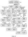
- FIGS. 26 , 27 , and 28 The unified one-way proxy state machine involved in operating the one-way proxy system of FIG. 3 is shown in FIGS. 26 , 27 , and 28 .
- the rectangular boxes and embedded ovals contains information on the states of the system.
- oval 170 indicates that the portion of one-way proxy system 40 that is shown as being adjacent to TCP endpoint A in FIG. 3 (called “rep side A”) is in a “close” state.
- oval 172 indicates that the portion of one-way proxy system 40 that is shown as being adjacent to TCP endpoint B in FIG. 3 (called “rep side B”) is in a “close” state.
- state 168 is an initial system state in which no session has been established and in which there is no system activity.
- the lines between the boxes in the FIGS. indicate transitions between states.
- the annotations on the lines indicate the system activities that take place that cause these transitions.
- line 174 in FIG. 26 indicates that TCP endpoint A is starting a TCP session.
- the annotations on line 174 indicate that this transition occurs when receiver B′ of one-way proxy system 40 receives a SYN from TCP endpoint A and sends the SYN from A′ to TCP endpoint B.
- the sequence number (SYN) that is received from TCP endpoint A is retained by the one-way proxy system. The same sequence number is transmitted to TCP endpoint B.
- step 176 the TCP session creation process has been initiated.
- B has sent an ACK in response to the SYN from A′ and has sent its own SYN to A′.
- SYN-ACK in the FIGS. refers to the situation in which both a SYN and ACK have been sent.
- Line 178 indicates how the adapter 56 passes through a SYN and an ACK to TCP endpoint A.
- the sequence number and acknowledgement number have the same values as the corresponding sequence number and acknowledgement number received from TCP endpoint B.
- This (along with the time stamp functions described in connection with FIGS. 6 , 7 , 9 , and 10 ) provides fail close support for the one-way proxy system. In the event the system enters hardware bypass mode, the use of unmodified initial sequence numbers and appropriate time stamp values allows the TCP session to survive.
- the TCP session is established when the interceptor receives an ACK from A and passes it to B. This ACK was sent in response to the SYN received from B in connection with transition 178 .
- line 184 indicates the path taken when B initiates the TCP session.
- the TCP interceptor 50 receives a SYN-ACK from A and passes it to TCP endpoint B.
- the initial sequence numbers are retained as described in connection with transitions 174 and 178 .
- Line 188 shows how the final step in creating the B-initiated TCP session involves using TCP adapter 56 to receive an ACK from B and pass it to A.
- the TCP session has been established.
- the preservation of the SYN (sequence number) through the one-way proxy system 40 by passing the SYN through the one-way proxy system 40 unchanged during transitions 178 and 186 supports so-called “fail close” behavior in which the TCP session survives even in the event of a hardware bypass.
- FIGS. 27 and 28 are state machine representations of the process of terminating the TCP session between TCP endpoints A and B using the one-way proxy system 40 .
- FIG. 27 shows termination operations when termination is initiated by starting to close the B to A data stream.
- FIG. 28 shows termination operations when termination is initiated by starting to close the A to B stream.
- state 190 represents the state of the FIG. 3 system when the B to A stream has been partly closed.
- the adapter passes the same FIN to A that was received from B. no ACK is sent to B by the proxy system 40 .
- State 192 represents the state when the B to A stream has been completely closed. In the transition between states 190 and 192 , the ACK is only sent to B after it has been received from A. In a conventional two-way proxy arrangement, proxy A′ would have sent an ACK in direct response to a FIN from B. In the one-way proxy system, in contrast, the one-way proxy system 40 waits for the ACK from TCP endpoint A.
- state 198 the B to A stream and the A to B′ stream are completely closed and the A′ to B stream has been partly closed.
- the analyzer 44 presents a CLOSE signal to indicate that data processing operations by the analyzer 44 are finished.
- state 200 the B to A stream has been partly closed.
- the A to B′ stream has been closed and the A′ to B stream has been partly closed.
- FIG. 28 shows how the TCP session is terminated when termination is initiated by closing the A to B direction.
- a FIN has been received from A which has been passed to the analyzer.
- An ACK has been sent to A in response to the received FIN.
- the one-way proxy system of the present invention passes many TCP options and properties through system 40 either unchanged or modified in a way that makes the one-way proxy transparent.
- the present invention therefore eliminates much of the overhead associated with conventional systems to improve system efficiency, while improving reliability by providing fail close support.
Abstract
Description
Claims (20)
Priority Applications (2)
| Application Number | Priority Date | Filing Date | Title |
|---|---|---|---|
| US11/117,756 US8069250B2 (en) | 2005-04-28 | 2005-04-28 | One-way proxy system |
| PCT/US2006/013772 WO2006115798A2 (en) | 2005-04-28 | 2006-04-12 | One-way proxy system |
Applications Claiming Priority (1)
| Application Number | Priority Date | Filing Date | Title |
|---|---|---|---|
| US11/117,756 US8069250B2 (en) | 2005-04-28 | 2005-04-28 | One-way proxy system |
Publications (2)
| Publication Number | Publication Date |
|---|---|
| US20060248582A1 US20060248582A1 (en) | 2006-11-02 |
| US8069250B2 true US8069250B2 (en) | 2011-11-29 |
Family
ID=37215211
Family Applications (1)
| Application Number | Title | Priority Date | Filing Date |
|---|---|---|---|
| US11/117,756 Active 2029-10-20 US8069250B2 (en) | 2005-04-28 | 2005-04-28 | One-way proxy system |
Country Status (2)
| Country | Link |
|---|---|
| US (1) | US8069250B2 (en) |
| WO (1) | WO2006115798A2 (en) |
Cited By (3)
| Publication number | Priority date | Publication date | Assignee | Title |
|---|---|---|---|---|
| US20110225295A1 (en) * | 2007-12-26 | 2011-09-15 | Underwood Gerald E | Method and system for monitoring and analyzing of ip networks elements |
| US20140283000A1 (en) * | 2013-03-14 | 2014-09-18 | Cisco Technology, Inc. | Proxy that Switches from Light-Weight Monitor Mode to Full Proxy |
| US10574706B2 (en) * | 2016-05-29 | 2020-02-25 | Flash Networks, Ltd | Method and system for upload optimization |
Families Citing this family (165)
| Publication number | Priority date | Publication date | Assignee | Title |
|---|---|---|---|---|
| US7620990B2 (en) * | 2004-01-30 | 2009-11-17 | Microsoft Corporation | System and method for unpacking packed executables for malware evaluation |
| US7730530B2 (en) * | 2004-01-30 | 2010-06-01 | Microsoft Corporation | System and method for gathering exhibited behaviors on a .NET executable module in a secure manner |
| US7913305B2 (en) * | 2004-01-30 | 2011-03-22 | Microsoft Corporation | System and method for detecting malware in an executable code module according to the code module's exhibited behavior |
| US8566946B1 (en) | 2006-04-20 | 2013-10-22 | Fireeye, Inc. | Malware containment on connection |
| US8584239B2 (en) | 2004-04-01 | 2013-11-12 | Fireeye, Inc. | Virtual machine with dynamic data flow analysis |
| US7587537B1 (en) | 2007-11-30 | 2009-09-08 | Altera Corporation | Serializer-deserializer circuits formed from input-output circuit registers |
| US8549638B2 (en) | 2004-06-14 | 2013-10-01 | Fireeye, Inc. | System and method of containing computer worms |
| US8881282B1 (en) | 2004-04-01 | 2014-11-04 | Fireeye, Inc. | Systems and methods for malware attack detection and identification |
| US8898788B1 (en) | 2004-04-01 | 2014-11-25 | Fireeye, Inc. | Systems and methods for malware attack prevention |
| US8171553B2 (en) | 2004-04-01 | 2012-05-01 | Fireeye, Inc. | Heuristic based capture with replay to virtual machine |
| US9106694B2 (en) | 2004-04-01 | 2015-08-11 | Fireeye, Inc. | Electronic message analysis for malware detection |
| US8793787B2 (en) | 2004-04-01 | 2014-07-29 | Fireeye, Inc. | Detecting malicious network content using virtual environment components |
| US8528086B1 (en) | 2004-04-01 | 2013-09-03 | Fireeye, Inc. | System and method of detecting computer worms |
| US8085669B2 (en) * | 2005-11-07 | 2011-12-27 | Nec Corporation | Session relay device and session relay method |
| US8041946B2 (en) * | 2006-02-28 | 2011-10-18 | The Boeing Company | Data transfer between networks operating at different security levels |
| US9762536B2 (en) * | 2006-06-27 | 2017-09-12 | Waterfall Security Solutions Ltd. | One way secure link |
| IL177756A (en) * | 2006-08-29 | 2014-11-30 | Lior Frenkel | Encryption-based attack prevention |
| US8155002B2 (en) * | 2006-09-21 | 2012-04-10 | Arris Group, Inc. | Method for automatically inflating the receive window size in TCP connections |
| US9258230B2 (en) * | 2006-10-17 | 2016-02-09 | Hewlett Packard Enterprise Development Lp | In flight TCP window adjustment to improve network performance |
| IL180020A (en) | 2006-12-12 | 2013-03-24 | Waterfall Security Solutions Ltd | Encryption -and decryption-enabled interfaces |
| US8223205B2 (en) * | 2007-10-24 | 2012-07-17 | Waterfall Solutions Ltd. | Secure implementation of network-based sensors |
| US8588064B2 (en) * | 2008-01-17 | 2013-11-19 | Qualcomm Incorporated | Transport layer that warns application of potential bottleneck and methods thereof |
| US8438303B2 (en) * | 2008-07-15 | 2013-05-07 | International Business Machines Corporation | Audit logging and role based security using one way proxy architecture |
| US8850571B2 (en) | 2008-11-03 | 2014-09-30 | Fireeye, Inc. | Systems and methods for detecting malicious network content |
| US8997219B2 (en) | 2008-11-03 | 2015-03-31 | Fireeye, Inc. | Systems and methods for detecting malicious PDF network content |
| US8619792B1 (en) * | 2009-01-13 | 2013-12-31 | Coherent Technical Services, Inc. | Selective multi-modal transmission alteration |
| US8832829B2 (en) | 2009-09-30 | 2014-09-09 | Fireeye, Inc. | Network-based binary file extraction and analysis for malware detection |
| US9712374B1 (en) * | 2010-08-18 | 2017-07-18 | Juniper Networks, Inc. | Network services resource management |
| US9519782B2 (en) | 2012-02-24 | 2016-12-13 | Fireeye, Inc. | Detecting malicious network content |
| US9635037B2 (en) | 2012-09-06 | 2017-04-25 | Waterfall Security Solutions Ltd. | Remote control of secure installations |
| US10572665B2 (en) | 2012-12-28 | 2020-02-25 | Fireeye, Inc. | System and method to create a number of breakpoints in a virtual machine via virtual machine trapping events |
| US8990944B1 (en) | 2013-02-23 | 2015-03-24 | Fireeye, Inc. | Systems and methods for automatically detecting backdoors |
| US9176843B1 (en) | 2013-02-23 | 2015-11-03 | Fireeye, Inc. | Framework for efficient security coverage of mobile software applications |
| US9009823B1 (en) | 2013-02-23 | 2015-04-14 | Fireeye, Inc. | Framework for efficient security coverage of mobile software applications installed on mobile devices |
| US9367681B1 (en) | 2013-02-23 | 2016-06-14 | Fireeye, Inc. | Framework for efficient security coverage of mobile software applications using symbolic execution to reach regions of interest within an application |
| US9195829B1 (en) | 2013-02-23 | 2015-11-24 | Fireeye, Inc. | User interface with real-time visual playback along with synchronous textual analysis log display and event/time index for anomalous behavior detection in applications |
| US9626509B1 (en) | 2013-03-13 | 2017-04-18 | Fireeye, Inc. | Malicious content analysis with multi-version application support within single operating environment |
| US9104867B1 (en) | 2013-03-13 | 2015-08-11 | Fireeye, Inc. | Malicious content analysis using simulated user interaction without user involvement |
| US9355247B1 (en) | 2013-03-13 | 2016-05-31 | Fireeye, Inc. | File extraction from memory dump for malicious content analysis |
| US9311479B1 (en) | 2013-03-14 | 2016-04-12 | Fireeye, Inc. | Correlation and consolidation of analytic data for holistic view of a malware attack |
| US9430646B1 (en) | 2013-03-14 | 2016-08-30 | Fireeye, Inc. | Distributed systems and methods for automatically detecting unknown bots and botnets |
| US10713358B2 (en) | 2013-03-15 | 2020-07-14 | Fireeye, Inc. | System and method to extract and utilize disassembly features to classify software intent |
| WO2014145805A1 (en) | 2013-03-15 | 2014-09-18 | Mandiant, Llc | System and method employing structured intelligence to verify and contain threats at endpoints |
| US9419975B2 (en) | 2013-04-22 | 2016-08-16 | Waterfall Security Solutions Ltd. | Bi-directional communication over a one-way link |
| US9495180B2 (en) | 2013-05-10 | 2016-11-15 | Fireeye, Inc. | Optimized resource allocation for virtual machines within a malware content detection system |
| US9635039B1 (en) | 2013-05-13 | 2017-04-25 | Fireeye, Inc. | Classifying sets of malicious indicators for detecting command and control communications associated with malware |
| US10133863B2 (en) | 2013-06-24 | 2018-11-20 | Fireeye, Inc. | Zero-day discovery system |
| US9300686B2 (en) | 2013-06-28 | 2016-03-29 | Fireeye, Inc. | System and method for detecting malicious links in electronic messages |
| US10515214B1 (en) | 2013-09-30 | 2019-12-24 | Fireeye, Inc. | System and method for classifying malware within content created during analysis of a specimen |
| US9628507B2 (en) | 2013-09-30 | 2017-04-18 | Fireeye, Inc. | Advanced persistent threat (APT) detection center |
| US9690936B1 (en) | 2013-09-30 | 2017-06-27 | Fireeye, Inc. | Multistage system and method for analyzing obfuscated content for malware |
| US9171160B2 (en) | 2013-09-30 | 2015-10-27 | Fireeye, Inc. | Dynamically adaptive framework and method for classifying malware using intelligent static, emulation, and dynamic analyses |
| US9294501B2 (en) | 2013-09-30 | 2016-03-22 | Fireeye, Inc. | Fuzzy hash of behavioral results |
| US9736179B2 (en) | 2013-09-30 | 2017-08-15 | Fireeye, Inc. | System, apparatus and method for using malware analysis results to drive adaptive instrumentation of virtual machines to improve exploit detection |
| US9921978B1 (en) | 2013-11-08 | 2018-03-20 | Fireeye, Inc. | System and method for enhanced security of storage devices |
| US9747446B1 (en) | 2013-12-26 | 2017-08-29 | Fireeye, Inc. | System and method for run-time object classification |
| US9756074B2 (en) | 2013-12-26 | 2017-09-05 | Fireeye, Inc. | System and method for IPS and VM-based detection of suspicious objects |
| US20150188949A1 (en) * | 2013-12-31 | 2015-07-02 | Lookout, Inc. | Cloud-based network security |
| US9740857B2 (en) | 2014-01-16 | 2017-08-22 | Fireeye, Inc. | Threat-aware microvisor |
| US9262635B2 (en) | 2014-02-05 | 2016-02-16 | Fireeye, Inc. | Detection efficacy of virtual machine-based analysis with application specific events |
| US9241010B1 (en) | 2014-03-20 | 2016-01-19 | Fireeye, Inc. | System and method for network behavior detection |
| US10242185B1 (en) | 2014-03-21 | 2019-03-26 | Fireeye, Inc. | Dynamic guest image creation and rollback |
| US9591015B1 (en) | 2014-03-28 | 2017-03-07 | Fireeye, Inc. | System and method for offloading packet processing and static analysis operations |
| US9223972B1 (en) | 2014-03-31 | 2015-12-29 | Fireeye, Inc. | Dynamically remote tuning of a malware content detection system |
| US9432389B1 (en) | 2014-03-31 | 2016-08-30 | Fireeye, Inc. | System, apparatus and method for detecting a malicious attack based on static analysis of a multi-flow object |
| US9973531B1 (en) | 2014-06-06 | 2018-05-15 | Fireeye, Inc. | Shellcode detection |
| US9594912B1 (en) | 2014-06-06 | 2017-03-14 | Fireeye, Inc. | Return-oriented programming detection |
| US9438623B1 (en) | 2014-06-06 | 2016-09-06 | Fireeye, Inc. | Computer exploit detection using heap spray pattern matching |
| US9397939B2 (en) * | 2014-06-24 | 2016-07-19 | International Business Machines Corporation | Hybrid approach for performance enhancing proxies |
| US10084813B2 (en) | 2014-06-24 | 2018-09-25 | Fireeye, Inc. | Intrusion prevention and remedy system |
| US10805340B1 (en) | 2014-06-26 | 2020-10-13 | Fireeye, Inc. | Infection vector and malware tracking with an interactive user display |
| US9398028B1 (en) | 2014-06-26 | 2016-07-19 | Fireeye, Inc. | System, device and method for detecting a malicious attack based on communcations between remotely hosted virtual machines and malicious web servers |
| US10002252B2 (en) | 2014-07-01 | 2018-06-19 | Fireeye, Inc. | Verification of trusted threat-aware microvisor |
| US9363280B1 (en) | 2014-08-22 | 2016-06-07 | Fireeye, Inc. | System and method of detecting delivery of malware using cross-customer data |
| US10671726B1 (en) | 2014-09-22 | 2020-06-02 | Fireeye Inc. | System and method for malware analysis using thread-level event monitoring |
| US9773112B1 (en) | 2014-09-29 | 2017-09-26 | Fireeye, Inc. | Exploit detection of malware and malware families |
| US10027689B1 (en) | 2014-09-29 | 2018-07-17 | Fireeye, Inc. | Interactive infection visualization for improved exploit detection and signature generation for malware and malware families |
| IL235175A (en) | 2014-10-19 | 2017-08-31 | Frenkel Lior | Secure remote desktop |
| US9515777B2 (en) * | 2014-10-23 | 2016-12-06 | International Business Machines Corporation | Snoop virtual receiver time |
| US9690933B1 (en) | 2014-12-22 | 2017-06-27 | Fireeye, Inc. | Framework for classifying an object as malicious with machine learning for deploying updated predictive models |
| US10075455B2 (en) | 2014-12-26 | 2018-09-11 | Fireeye, Inc. | Zero-day rotating guest image profile |
| US9934376B1 (en) | 2014-12-29 | 2018-04-03 | Fireeye, Inc. | Malware detection appliance architecture |
| US9838417B1 (en) | 2014-12-30 | 2017-12-05 | Fireeye, Inc. | Intelligent context aware user interaction for malware detection |
| US10148693B2 (en) | 2015-03-25 | 2018-12-04 | Fireeye, Inc. | Exploit detection system |
| US9690606B1 (en) | 2015-03-25 | 2017-06-27 | Fireeye, Inc. | Selective system call monitoring |
| US9438613B1 (en) | 2015-03-30 | 2016-09-06 | Fireeye, Inc. | Dynamic content activation for automated analysis of embedded objects |
| US9483644B1 (en) | 2015-03-31 | 2016-11-01 | Fireeye, Inc. | Methods for detecting file altering malware in VM based analysis |
| US10474813B1 (en) | 2015-03-31 | 2019-11-12 | Fireeye, Inc. | Code injection technique for remediation at an endpoint of a network |
| US10417031B2 (en) | 2015-03-31 | 2019-09-17 | Fireeye, Inc. | Selective virtualization for security threat detection |
| US9654485B1 (en) | 2015-04-13 | 2017-05-16 | Fireeye, Inc. | Analytics-based security monitoring system and method |
| US9594904B1 (en) | 2015-04-23 | 2017-03-14 | Fireeye, Inc. | Detecting malware based on reflection |
| US10642753B1 (en) | 2015-06-30 | 2020-05-05 | Fireeye, Inc. | System and method for protecting a software component running in virtual machine using a virtualization layer |
| US10726127B1 (en) | 2015-06-30 | 2020-07-28 | Fireeye, Inc. | System and method for protecting a software component running in a virtual machine through virtual interrupts by the virtualization layer |
| US10454950B1 (en) | 2015-06-30 | 2019-10-22 | Fireeye, Inc. | Centralized aggregation technique for detecting lateral movement of stealthy cyber-attacks |
| US11113086B1 (en) | 2015-06-30 | 2021-09-07 | Fireeye, Inc. | Virtual system and method for securing external network connectivity |
| US10715542B1 (en) | 2015-08-14 | 2020-07-14 | Fireeye, Inc. | Mobile application risk analysis |
| US10176321B2 (en) | 2015-09-22 | 2019-01-08 | Fireeye, Inc. | Leveraging behavior-based rules for malware family classification |
| US10785150B2 (en) * | 2015-09-25 | 2020-09-22 | Intel Corporation | CRC update mechanism |
| US10033747B1 (en) | 2015-09-29 | 2018-07-24 | Fireeye, Inc. | System and method for detecting interpreter-based exploit attacks |
| US10210329B1 (en) | 2015-09-30 | 2019-02-19 | Fireeye, Inc. | Method to detect application execution hijacking using memory protection |
| US9825989B1 (en) | 2015-09-30 | 2017-11-21 | Fireeye, Inc. | Cyber attack early warning system |
| US9825976B1 (en) | 2015-09-30 | 2017-11-21 | Fireeye, Inc. | Detection and classification of exploit kits |
| US10706149B1 (en) | 2015-09-30 | 2020-07-07 | Fireeye, Inc. | Detecting delayed activation malware using a primary controller and plural time controllers |
| US10817606B1 (en) | 2015-09-30 | 2020-10-27 | Fireeye, Inc. | Detecting delayed activation malware using a run-time monitoring agent and time-dilation logic |
| US10601865B1 (en) | 2015-09-30 | 2020-03-24 | Fireeye, Inc. | Detection of credential spearphishing attacks using email analysis |
| US10284575B2 (en) | 2015-11-10 | 2019-05-07 | Fireeye, Inc. | Launcher for setting analysis environment variations for malware detection |
| US10447728B1 (en) | 2015-12-10 | 2019-10-15 | Fireeye, Inc. | Technique for protecting guest processes using a layered virtualization architecture |
| US10846117B1 (en) | 2015-12-10 | 2020-11-24 | Fireeye, Inc. | Technique for establishing secure communication between host and guest processes of a virtualization architecture |
| US10108446B1 (en) | 2015-12-11 | 2018-10-23 | Fireeye, Inc. | Late load technique for deploying a virtualization layer underneath a running operating system |
| US10050998B1 (en) | 2015-12-30 | 2018-08-14 | Fireeye, Inc. | Malicious message analysis system |
| US10565378B1 (en) | 2015-12-30 | 2020-02-18 | Fireeye, Inc. | Exploit of privilege detection framework |
| US10133866B1 (en) | 2015-12-30 | 2018-11-20 | Fireeye, Inc. | System and method for triggering analysis of an object for malware in response to modification of that object |
| US10621338B1 (en) | 2015-12-30 | 2020-04-14 | Fireeye, Inc. | Method to detect forgery and exploits using last branch recording registers |
| US11552986B1 (en) | 2015-12-31 | 2023-01-10 | Fireeye Security Holdings Us Llc | Cyber-security framework for application of virtual features |
| US9824216B1 (en) | 2015-12-31 | 2017-11-21 | Fireeye, Inc. | Susceptible environment detection system |
| US10581874B1 (en) | 2015-12-31 | 2020-03-03 | Fireeye, Inc. | Malware detection system with contextual analysis |
| IL250010B (en) | 2016-02-14 | 2020-04-30 | Waterfall Security Solutions Ltd | Secure connection with protected facilities |
| US10785255B1 (en) | 2016-03-25 | 2020-09-22 | Fireeye, Inc. | Cluster configuration within a scalable malware detection system |
| US10601863B1 (en) | 2016-03-25 | 2020-03-24 | Fireeye, Inc. | System and method for managing sensor enrollment |
| US10476906B1 (en) | 2016-03-25 | 2019-11-12 | Fireeye, Inc. | System and method for managing formation and modification of a cluster within a malware detection system |
| US10671721B1 (en) | 2016-03-25 | 2020-06-02 | Fireeye, Inc. | Timeout management services |
| US10893059B1 (en) | 2016-03-31 | 2021-01-12 | Fireeye, Inc. | Verification and enhancement using detection systems located at the network periphery and endpoint devices |
| US10169585B1 (en) | 2016-06-22 | 2019-01-01 | Fireeye, Inc. | System and methods for advanced malware detection through placement of transition events |
| US10462173B1 (en) | 2016-06-30 | 2019-10-29 | Fireeye, Inc. | Malware detection verification and enhancement by coordinating endpoint and malware detection systems |
| US10592678B1 (en) | 2016-09-09 | 2020-03-17 | Fireeye, Inc. | Secure communications between peers using a verified virtual trusted platform module |
| US10491627B1 (en) | 2016-09-29 | 2019-11-26 | Fireeye, Inc. | Advanced malware detection using similarity analysis |
| US10795991B1 (en) | 2016-11-08 | 2020-10-06 | Fireeye, Inc. | Enterprise search |
| US10587647B1 (en) | 2016-11-22 | 2020-03-10 | Fireeye, Inc. | Technique for malware detection capability comparison of network security devices |
| US10552610B1 (en) | 2016-12-22 | 2020-02-04 | Fireeye, Inc. | Adaptive virtual machine snapshot update framework for malware behavioral analysis |
| US10581879B1 (en) | 2016-12-22 | 2020-03-03 | Fireeye, Inc. | Enhanced malware detection for generated objects |
| US10523609B1 (en) | 2016-12-27 | 2019-12-31 | Fireeye, Inc. | Multi-vector malware detection and analysis |
| US10320634B2 (en) * | 2016-12-30 | 2019-06-11 | Logmein, Inc. | Data communications employing packet report messages |
| US10904286B1 (en) | 2017-03-24 | 2021-01-26 | Fireeye, Inc. | Detection of phishing attacks using similarity analysis |
| US10554507B1 (en) | 2017-03-30 | 2020-02-04 | Fireeye, Inc. | Multi-level control for enhanced resource and object evaluation management of malware detection system |
| US10902119B1 (en) | 2017-03-30 | 2021-01-26 | Fireeye, Inc. | Data extraction system for malware analysis |
| US10798112B2 (en) | 2017-03-30 | 2020-10-06 | Fireeye, Inc. | Attribute-controlled malware detection |
| US10791138B1 (en) | 2017-03-30 | 2020-09-29 | Fireeye, Inc. | Subscription-based malware detection |
| US10503904B1 (en) | 2017-06-29 | 2019-12-10 | Fireeye, Inc. | Ransomware detection and mitigation |
| US10601848B1 (en) | 2017-06-29 | 2020-03-24 | Fireeye, Inc. | Cyber-security system and method for weak indicator detection and correlation to generate strong indicators |
| US10855700B1 (en) | 2017-06-29 | 2020-12-01 | Fireeye, Inc. | Post-intrusion detection of cyber-attacks during lateral movement within networks |
| US10893068B1 (en) | 2017-06-30 | 2021-01-12 | Fireeye, Inc. | Ransomware file modification prevention technique |
| US10747872B1 (en) | 2017-09-27 | 2020-08-18 | Fireeye, Inc. | System and method for preventing malware evasion |
| US10805346B2 (en) | 2017-10-01 | 2020-10-13 | Fireeye, Inc. | Phishing attack detection |
| US11108809B2 (en) | 2017-10-27 | 2021-08-31 | Fireeye, Inc. | System and method for analyzing binary code for malware classification using artificial neural network techniques |
| US11271955B2 (en) | 2017-12-28 | 2022-03-08 | Fireeye Security Holdings Us Llc | Platform and method for retroactive reclassification employing a cybersecurity-based global data store |
| US11240275B1 (en) | 2017-12-28 | 2022-02-01 | Fireeye Security Holdings Us Llc | Platform and method for performing cybersecurity analyses employing an intelligence hub with a modular architecture |
| US11005860B1 (en) | 2017-12-28 | 2021-05-11 | Fireeye, Inc. | Method and system for efficient cybersecurity analysis of endpoint events |
| US10826931B1 (en) | 2018-03-29 | 2020-11-03 | Fireeye, Inc. | System and method for predicting and mitigating cybersecurity system misconfigurations |
| US10956477B1 (en) | 2018-03-30 | 2021-03-23 | Fireeye, Inc. | System and method for detecting malicious scripts through natural language processing modeling |
| US11003773B1 (en) | 2018-03-30 | 2021-05-11 | Fireeye, Inc. | System and method for automatically generating malware detection rule recommendations |
| US11558401B1 (en) | 2018-03-30 | 2023-01-17 | Fireeye Security Holdings Us Llc | Multi-vector malware detection data sharing system for improved detection |
| US11075930B1 (en) | 2018-06-27 | 2021-07-27 | Fireeye, Inc. | System and method for detecting repetitive cybersecurity attacks constituting an email campaign |
| US11314859B1 (en) | 2018-06-27 | 2022-04-26 | FireEye Security Holdings, Inc. | Cyber-security system and method for detecting escalation of privileges within an access token |
| US11228491B1 (en) | 2018-06-28 | 2022-01-18 | Fireeye Security Holdings Us Llc | System and method for distributed cluster configuration monitoring and management |
| US11316900B1 (en) | 2018-06-29 | 2022-04-26 | FireEye Security Holdings Inc. | System and method for automatically prioritizing rules for cyber-threat detection and mitigation |
| US11182473B1 (en) | 2018-09-13 | 2021-11-23 | Fireeye Security Holdings Us Llc | System and method for mitigating cyberattacks against processor operability by a guest process |
| US11763004B1 (en) | 2018-09-27 | 2023-09-19 | Fireeye Security Holdings Us Llc | System and method for bootkit detection |
| US11368475B1 (en) | 2018-12-21 | 2022-06-21 | Fireeye Security Holdings Us Llc | System and method for scanning remote services to locate stored objects with malware |
| CN109587163B (en) * | 2018-12-27 | 2022-08-16 | 网宿科技股份有限公司 | Protection method and device in DR mode |
| US11019044B2 (en) * | 2019-03-08 | 2021-05-25 | Gigamon Inc. | Correlating network flows through a proxy device |
| US11258806B1 (en) | 2019-06-24 | 2022-02-22 | Mandiant, Inc. | System and method for automatically associating cybersecurity intelligence to cyberthreat actors |
| US11556640B1 (en) | 2019-06-27 | 2023-01-17 | Mandiant, Inc. | Systems and methods for automated cybersecurity analysis of extracted binary string sets |
| US11392700B1 (en) | 2019-06-28 | 2022-07-19 | Fireeye Security Holdings Us Llc | System and method for supporting cross-platform data verification |
| US11886585B1 (en) | 2019-09-27 | 2024-01-30 | Musarubra Us Llc | System and method for identifying and mitigating cyberattacks through malicious position-independent code execution |
| US11637862B1 (en) | 2019-09-30 | 2023-04-25 | Mandiant, Inc. | System and method for surfacing cyber-security threats with a self-learning recommendation engine |
Citations (12)
| Publication number | Priority date | Publication date | Assignee | Title |
|---|---|---|---|---|
| US5941988A (en) | 1997-01-27 | 1999-08-24 | International Business Machines Corporation | Session and transport layer proxies via TCP glue |
| US5961605A (en) | 1997-02-06 | 1999-10-05 | Gte Laboratories Incorporated | Method and apparatus for acknowledging TCP data packets |
| US20020016851A1 (en) * | 2000-07-21 | 2002-02-07 | John Border | Method and system for providing buffer management in a perormance enhancing proxy architecture |
| US6473406B1 (en) * | 1997-07-31 | 2002-10-29 | Cisco Technology, Inc. | Method and apparatus for transparently proxying a connection |
| US20030043788A1 (en) * | 2001-09-06 | 2003-03-06 | Kddi Corporation | Packet repeater in asymmetrical transmissions |
| US20040034826A1 (en) * | 2000-09-13 | 2004-02-19 | Johan Johansson | Transport protocol checksum recalculation |
| US6822955B1 (en) | 1998-01-22 | 2004-11-23 | Nortel Networks Limited | Proxy server for TCP/IP network address portability |
| US6823372B1 (en) | 2002-09-13 | 2004-11-23 | Bellsouth Intellectual Property Corporation | System and method for reverse proxy service |
| US20040260801A1 (en) * | 2003-02-12 | 2004-12-23 | Actiontec Electronics, Inc. | Apparatus and methods for monitoring and controlling network activity using mobile communications devices |
| US6853617B2 (en) | 2001-05-09 | 2005-02-08 | Chiaro Networks, Ltd. | System and method for TCP connection protection switching |
| US20050063303A1 (en) * | 2003-07-29 | 2005-03-24 | Samuels Allen R. | TCP selective acknowledgements for communicating delivered and missed data packets |
| US7296073B1 (en) * | 2000-09-13 | 2007-11-13 | Network Appliance, Inc. | Mechanism to survive server failures when using the CIFS protocol |
Family Cites Families (1)
| Publication number | Priority date | Publication date | Assignee | Title |
|---|---|---|---|---|
| US7467720B2 (en) * | 2003-07-07 | 2008-12-23 | Wisconsin Label Corporation | Product display hanger strip |
-
2005
- 2005-04-28 US US11/117,756 patent/US8069250B2/en active Active
-
2006
- 2006-04-12 WO PCT/US2006/013772 patent/WO2006115798A2/en active Application Filing
Patent Citations (12)
| Publication number | Priority date | Publication date | Assignee | Title |
|---|---|---|---|---|
| US5941988A (en) | 1997-01-27 | 1999-08-24 | International Business Machines Corporation | Session and transport layer proxies via TCP glue |
| US5961605A (en) | 1997-02-06 | 1999-10-05 | Gte Laboratories Incorporated | Method and apparatus for acknowledging TCP data packets |
| US6473406B1 (en) * | 1997-07-31 | 2002-10-29 | Cisco Technology, Inc. | Method and apparatus for transparently proxying a connection |
| US6822955B1 (en) | 1998-01-22 | 2004-11-23 | Nortel Networks Limited | Proxy server for TCP/IP network address portability |
| US20020016851A1 (en) * | 2000-07-21 | 2002-02-07 | John Border | Method and system for providing buffer management in a perormance enhancing proxy architecture |
| US20040034826A1 (en) * | 2000-09-13 | 2004-02-19 | Johan Johansson | Transport protocol checksum recalculation |
| US7296073B1 (en) * | 2000-09-13 | 2007-11-13 | Network Appliance, Inc. | Mechanism to survive server failures when using the CIFS protocol |
| US6853617B2 (en) | 2001-05-09 | 2005-02-08 | Chiaro Networks, Ltd. | System and method for TCP connection protection switching |
| US20030043788A1 (en) * | 2001-09-06 | 2003-03-06 | Kddi Corporation | Packet repeater in asymmetrical transmissions |
| US6823372B1 (en) | 2002-09-13 | 2004-11-23 | Bellsouth Intellectual Property Corporation | System and method for reverse proxy service |
| US20040260801A1 (en) * | 2003-02-12 | 2004-12-23 | Actiontec Electronics, Inc. | Apparatus and methods for monitoring and controlling network activity using mobile communications devices |
| US20050063303A1 (en) * | 2003-07-29 | 2005-03-24 | Samuels Allen R. | TCP selective acknowledgements for communicating delivered and missed data packets |
Non-Patent Citations (2)
| Title |
|---|
| Jacobson et al., TCP Extensions for High Performance, Request for Comments (RFC) 1323, Network Working Group, May 1992. * |
| M. Chatel, "Classical versus Transparent IP Proxies," Request for Comments: 1919, Nework Working Group, pp. 1-35 (Mar. 1996). |
Cited By (5)
| Publication number | Priority date | Publication date | Assignee | Title |
|---|---|---|---|---|
| US20110225295A1 (en) * | 2007-12-26 | 2011-09-15 | Underwood Gerald E | Method and system for monitoring and analyzing of ip networks elements |
| US9088441B2 (en) * | 2007-12-26 | 2015-07-21 | Verizon Patent And Licensing Inc. | Method and system for monitoring and analyzing of IP networks elements |
| US20140283000A1 (en) * | 2013-03-14 | 2014-09-18 | Cisco Technology, Inc. | Proxy that Switches from Light-Weight Monitor Mode to Full Proxy |
| US9197650B2 (en) * | 2013-03-14 | 2015-11-24 | Cisco Technology, Inc. | Proxy that switches from light-weight monitor mode to full proxy |
| US10574706B2 (en) * | 2016-05-29 | 2020-02-25 | Flash Networks, Ltd | Method and system for upload optimization |
Also Published As
| Publication number | Publication date |
|---|---|
| WO2006115798A3 (en) | 2007-11-29 |
| WO2006115798A2 (en) | 2006-11-02 |
| US20060248582A1 (en) | 2006-11-02 |
Similar Documents
| Publication | Publication Date | Title |
|---|---|---|
| US8069250B2 (en) | One-way proxy system | |
| US7593331B2 (en) | Enhancing transmission reliability of monitored data | |
| US7006480B2 (en) | Method and system for using a backbone protocol to improve network performance | |
| US7962825B2 (en) | System and methods for high rate hardware-accelerated network protocol processing | |
| US8190960B1 (en) | Guaranteed inter-process communication | |
| EP1690391B1 (en) | Transparent optimization for transmission control protocol initial session establishment | |
| US7869355B2 (en) | Network receive interface for high bandwidth hardware-accelerated packet processing | |
| JP4274195B2 (en) | Method for transmitting multimedia data associated with a multimedia application, method for transmitting data, system for transmitting multimedia data in a distributed network, and communication protocol for enabling multimedia communication between computers | |
| US6393023B1 (en) | System and method for acknowledging receipt of messages within a packet based communication network | |
| KR100255501B1 (en) | Improving session and transport layer proxies via tcp glue | |
| KR101104046B1 (en) | Congestion reducing reliable transport packet retry engine | |
| US6321269B1 (en) | Optimized performance for transaction-oriented communications using stream-based network protocols | |
| JP5661868B2 (en) | Method and device for submitting at least one TCP data segment stream to inline content analysis, computer readable medium carrying one or more instruction sequences for performing the method, and computer program product | |
| US20070110046A1 (en) | Internet protocol optimizer | |
| US8611222B1 (en) | Selectively enabling packet concatenation based on a transaction boundary | |
| WO2015198201A1 (en) | Hybrid approach for performance enhancing proxies | |
| US7697441B2 (en) | Computer system with black hole management | |
| Eddy | Rfc 9293: Transmission control protocol (tcp) | |
| O'Malley et al. | TCP extensions considered harmful | |
| US8170057B2 (en) | Communication-processing apparatus and its method | |
| JP6268027B2 (en) | COMMUNICATION SYSTEM, TRANSMISSION DEVICE, AND COMMUNICATION METHOD | |
| KR20050059799A (en) | Apparatus and method to minimizing packet loss | |
| Fang | y-of Gradůate Studies | |
| KR20020038376A (en) | A method to improve Forwarding speed of a sliding window method | |
| O'Malley et al. | RFC1263: TCP Extensions Considered Harmful |
Legal Events
| Date | Code | Title | Description |
|---|---|---|---|
| AS | Assignment |
Owner name: BLUE LANE TECHNOLOGIES INC., CALIFORNIA Free format text: ASSIGNMENT OF ASSIGNORS INTEREST;ASSIGNORS:PANJWANI, DILEEP KUMAR;TOSHNIWAL, ROHIT K.;REEL/FRAME:016530/0500 Effective date: 20050427 |
|
| AS | Assignment |
Owner name: VMWARE, INC., CALIFORNIA Free format text: MERGER;ASSIGNOR:BLUE LANE TECHNOLOGIES INC.;REEL/FRAME:021691/0744 Effective date: 20081008 Owner name: VMWARE, INC.,CALIFORNIA Free format text: MERGER;ASSIGNOR:BLUE LANE TECHNOLOGIES INC.;REEL/FRAME:021691/0744 Effective date: 20081008 |
|
| STCF | Information on status: patent grant |
Free format text: PATENTED CASE |
|
| FPAY | Fee payment |
Year of fee payment: 4 |
|
| MAFP | Maintenance fee payment |
Free format text: PAYMENT OF MAINTENANCE FEE, 8TH YEAR, LARGE ENTITY (ORIGINAL EVENT CODE: M1552); ENTITY STATUS OF PATENT OWNER: LARGE ENTITY Year of fee payment: 8 |
|
| MAFP | Maintenance fee payment |
Free format text: PAYMENT OF MAINTENANCE FEE, 12TH YEAR, LARGE ENTITY (ORIGINAL EVENT CODE: M1553); ENTITY STATUS OF PATENT OWNER: LARGE ENTITY Year of fee payment: 12 |