US8067111B2 - Battery module having battery cell assembly with heat exchanger - Google Patents
Battery module having battery cell assembly with heat exchanger Download PDFInfo
- Publication number
- US8067111B2 US8067111B2 US12/164,780 US16478008A US8067111B2 US 8067111 B2 US8067111 B2 US 8067111B2 US 16478008 A US16478008 A US 16478008A US 8067111 B2 US8067111 B2 US 8067111B2
- Authority
- US
- United States
- Prior art keywords
- battery cell
- shaped frame
- frame member
- rectangular ring
- heat exchanger
- Prior art date
- Legal status (The legal status is an assumption and is not a legal conclusion. Google has not performed a legal analysis and makes no representation as to the accuracy of the status listed.)
- Active, expires
Links
Images


Classifications
-
- H—ELECTRICITY
- H01—ELECTRIC ELEMENTS
- H01M—PROCESSES OR MEANS, e.g. BATTERIES, FOR THE DIRECT CONVERSION OF CHEMICAL ENERGY INTO ELECTRICAL ENERGY
- H01M50/00—Constructional details or processes of manufacture of the non-active parts of electrochemical cells other than fuel cells, e.g. hybrid cells
- H01M50/20—Mountings; Secondary casings or frames; Racks, modules or packs; Suspension devices; Shock absorbers; Transport or carrying devices; Holders
-
- H—ELECTRICITY
- H01—ELECTRIC ELEMENTS
- H01M—PROCESSES OR MEANS, e.g. BATTERIES, FOR THE DIRECT CONVERSION OF CHEMICAL ENERGY INTO ELECTRICAL ENERGY
- H01M10/00—Secondary cells; Manufacture thereof
- H01M10/05—Accumulators with non-aqueous electrolyte
- H01M10/052—Li-accumulators
-
- H—ELECTRICITY
- H01—ELECTRIC ELEMENTS
- H01M—PROCESSES OR MEANS, e.g. BATTERIES, FOR THE DIRECT CONVERSION OF CHEMICAL ENERGY INTO ELECTRICAL ENERGY
- H01M10/00—Secondary cells; Manufacture thereof
- H01M10/05—Accumulators with non-aqueous electrolyte
- H01M10/058—Construction or manufacture
-
- H—ELECTRICITY
- H01—ELECTRIC ELEMENTS
- H01M—PROCESSES OR MEANS, e.g. BATTERIES, FOR THE DIRECT CONVERSION OF CHEMICAL ENERGY INTO ELECTRICAL ENERGY
- H01M10/00—Secondary cells; Manufacture thereof
- H01M10/60—Heating or cooling; Temperature control
- H01M10/61—Types of temperature control
- H01M10/613—Cooling or keeping cold
-
- H—ELECTRICITY
- H01—ELECTRIC ELEMENTS
- H01M—PROCESSES OR MEANS, e.g. BATTERIES, FOR THE DIRECT CONVERSION OF CHEMICAL ENERGY INTO ELECTRICAL ENERGY
- H01M10/00—Secondary cells; Manufacture thereof
- H01M10/60—Heating or cooling; Temperature control
- H01M10/64—Heating or cooling; Temperature control characterised by the shape of the cells
- H01M10/647—Prismatic or flat cells, e.g. pouch cells
-
- H—ELECTRICITY
- H01—ELECTRIC ELEMENTS
- H01M—PROCESSES OR MEANS, e.g. BATTERIES, FOR THE DIRECT CONVERSION OF CHEMICAL ENERGY INTO ELECTRICAL ENERGY
- H01M10/00—Secondary cells; Manufacture thereof
- H01M10/60—Heating or cooling; Temperature control
- H01M10/65—Means for temperature control structurally associated with the cells
- H01M10/655—Solid structures for heat exchange or heat conduction
- H01M10/6556—Solid parts with flow channel passages or pipes for heat exchange
- H01M10/6557—Solid parts with flow channel passages or pipes for heat exchange arranged between the cells
-
- H—ELECTRICITY
- H01—ELECTRIC ELEMENTS
- H01M—PROCESSES OR MEANS, e.g. BATTERIES, FOR THE DIRECT CONVERSION OF CHEMICAL ENERGY INTO ELECTRICAL ENERGY
- H01M10/00—Secondary cells; Manufacture thereof
- H01M10/60—Heating or cooling; Temperature control
- H01M10/65—Means for temperature control structurally associated with the cells
- H01M10/656—Means for temperature control structurally associated with the cells characterised by the type of heat-exchange fluid
- H01M10/6561—Gases
- H01M10/6566—Means within the gas flow to guide the flow around one or more cells, e.g. manifolds, baffles or other barriers
-
- H—ELECTRICITY
- H01—ELECTRIC ELEMENTS
- H01M—PROCESSES OR MEANS, e.g. BATTERIES, FOR THE DIRECT CONVERSION OF CHEMICAL ENERGY INTO ELECTRICAL ENERGY
- H01M10/00—Secondary cells; Manufacture thereof
- H01M10/60—Heating or cooling; Temperature control
- H01M10/65—Means for temperature control structurally associated with the cells
- H01M10/656—Means for temperature control structurally associated with the cells characterised by the type of heat-exchange fluid
- H01M10/6567—Liquids
-
- Y—GENERAL TAGGING OF NEW TECHNOLOGICAL DEVELOPMENTS; GENERAL TAGGING OF CROSS-SECTIONAL TECHNOLOGIES SPANNING OVER SEVERAL SECTIONS OF THE IPC; TECHNICAL SUBJECTS COVERED BY FORMER USPC CROSS-REFERENCE ART COLLECTIONS [XRACs] AND DIGESTS
- Y02—TECHNOLOGIES OR APPLICATIONS FOR MITIGATION OR ADAPTATION AGAINST CLIMATE CHANGE
- Y02E—REDUCTION OF GREENHOUSE GAS [GHG] EMISSIONS, RELATED TO ENERGY GENERATION, TRANSMISSION OR DISTRIBUTION
- Y02E60/00—Enabling technologies; Technologies with a potential or indirect contribution to GHG emissions mitigation
- Y02E60/10—Energy storage using batteries
-
- Y—GENERAL TAGGING OF NEW TECHNOLOGICAL DEVELOPMENTS; GENERAL TAGGING OF CROSS-SECTIONAL TECHNOLOGIES SPANNING OVER SEVERAL SECTIONS OF THE IPC; TECHNICAL SUBJECTS COVERED BY FORMER USPC CROSS-REFERENCE ART COLLECTIONS [XRACs] AND DIGESTS
- Y02—TECHNOLOGIES OR APPLICATIONS FOR MITIGATION OR ADAPTATION AGAINST CLIMATE CHANGE
- Y02P—CLIMATE CHANGE MITIGATION TECHNOLOGIES IN THE PRODUCTION OR PROCESSING OF GOODS
- Y02P70/00—Climate change mitigation technologies in the production process for final industrial or consumer products
- Y02P70/50—Manufacturing or production processes characterised by the final manufactured product
Definitions
- This application relates generally to a battery module having a battery cell assembly with a heat exchanger.
- Battery packs generate heat during usage. To prevent degradation of the battery packs, the battery packs should be cooled. However, another cooling system may not uniformly cool battery cells in a battery pack. The inventors herein have recognized that if battery cells in a battery pack are not uniformly cooled, the battery cells can undesirably have differing operational characteristics including differing output voltages.
- the inventors herein have recognized a need for an improved battery module that minimizes and/or eliminates the above-mentioned deficiency.
- the battery cell assembly includes a first battery cell having a first side and a second side.
- the battery cell assembly further includes a second battery cell having a first side and a second side.
- the first side of the second battery cell contacts the second side of the first battery cell.
- the battery cell assembly further includes a heat exchanger having a first side and a second side.
- the first side of the heat exchanger contacts the second side of the second battery cell.
- the battery cell assembly further includes a third battery cell having a first side and a second side.
- the first side of the third battery cell contacts the second side of the heat exchanger.
- the heat exchanger is configured to remove heat energy from the first, second, and third battery cells to maintain the first, second, and third battery cells at substantially a desired temperature.
- the battery module includes a first battery cell assembly having a first battery cell with a first side and a second side.
- the first battery cell assembly further includes a second battery cell with a first side and a second side.
- the first side of the second battery cell contacts the second side of the first battery cell.
- the first battery cell assembly further includes a first heat exchanger with a first side and a second side.
- the first side of the first heat exchanger contacts the second side of the second battery cell.
- the first battery cell assembly further includes a third battery cell with a first side and a second side. The first side of the third battery cell contacts the second side of the first heat exchanger.
- the first heat exchanger is configured to remove heat energy from the first, second, and third battery cells to maintain the first, second, and third battery cells at substantially a desired temperature.
- the battery module further includes a second battery cell assembly having a fourth battery cell with a first side and a second side. The first side of the fourth battery cell contacts the second side of the third battery cell of the first battery cell assembly.
- the second battery cell assembly further includes a second heat exchanger with a first side and a second side. The first side of the second heat exchanger contacts the second side of the fourth battery cell.
- the second battery cell assembly further includes a fifth battery cell with a first side and a second side. The first side of the fifth battery cell contacts the second side of the second heat exchanger.
- the second battery cell assembly further includes a sixth battery cell with a first side and a second side.
- the first side of the sixth battery cell contacts the second side of the fifth battery cell.
- the second heat exchanger is configured to remove heat energy from the fourth, fifth and sixth battery cells to maintain the fourth, fifth and sixth battery cells at substantially the desired temperature.
- FIG. 1 is a schematic of a battery module in accordance with an exemplary embodiment
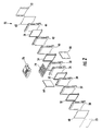
- FIG. 2 is an exploded schematic of a portion of the battery module of FIG. 1 ;
- FIG. 3 is an exploded schematic of a battery cell assembly in accordance with another exemplary embodiment, utilized in the battery module of FIG. 2 ;
- FIG. 4 is another schematic of the battery cell assembly of FIG. 3 ;
- FIG. 5 is another schematic of the battery cell assembly of FIG. 3 ;
- FIG. 6 is a cross-sectional schematic of a top portion of the battery cell assembly of FIG. 3 ;
- FIG. 7 is a cross-sectional schematic of a bottom portion of the battery cell assembly of FIG. 3 ;
- FIG. 8 is a schematic of a first side of a first rectangular ring-shaped frame member utilized in the battery cell assembly of FIG. 3 ;
- FIG. 9 is a schematic of a bottom portion of the first side of the first rectangular ring-shaped frame member of FIG. 8 ;
- FIG. 10 is a schematic of a top portion of the first side of the first rectangular ring-shaped frame member of FIG. 8 ;
- FIG. 11 is a schematic of a second side of the first rectangular ring-shaped frame member of FIG. 8 ;
- FIG. 12 is a schematic of a bottom portion of the second side of the first rectangular ring-shaped frame member of FIG. 11 ;
- FIG. 13 is a schematic of a top portion of the second side of the first rectangular ring-shaped frame member of FIG. 11 ;
- FIG. 14 is a schematic of a first side of a first battery cell utilized in the battery cell assembly of FIG. 3 ;
- FIG. 15 is a schematic of a second side of the first battery cell of FIG. 14 ;
- FIG. 16 is a schematic of a first side of a first securement ring-shaped member utilized in the battery cell assembly of FIG. 3 ;
- FIG. 17 is a schematic of a second side of the first securement ring-shaped member of FIG. 16 ;
- FIG. 18 is a schematic of a first side of a second rectangular ring-shaped frame member utilized in the battery cell assembly of FIG. 3 ;
- FIG. 19 is a schematic of a bottom portion of the first side of the second rectangular ring-shaped frame member of FIG. 18 ;
- FIG. 20 is a schematic of a top portion of the first side of the second rectangular ring-shaped frame member of FIG. 18 ;
- FIG. 21 is a schematic of a second side of the second rectangular ring-shaped frame member of FIG. 18 ;
- FIG. 22 is a schematic of a bottom portion of the second side of the second rectangular ring-shaped frame member of FIG. 21 ;
- FIG. 23 is a schematic of a top portion of the second side of the second rectangular ring-shaped frame member of FIG. 21 ;
- FIG. 24 is a schematic of a first side of a heat exchanger utilized in the battery cell assembly of FIG. 3 ;
- FIG. 25 is a schematic of a second side of the heat exchanger of FIG. 24 ;
- FIG. 26 is a cross-sectional schematic of the heat exchanger of FIG. 24 ;
- FIG. 27 is a schematic of a first side of a second securement ring-shaped member utilized in the battery cell assembly of FIG. 3 ;
- FIG. 28 is a schematic of a second side of the second securement ring-shaped member of FIG. 27 ;
- FIG. 29 is a schematic of a first side of a third rectangular ring-shaped frame member utilized in the battery cell assembly of FIG. 3 ;
- FIG. 30 is a schematic of a bottom portion of the first side of the third rectangular ring-shaped frame member of FIG. 29 ;
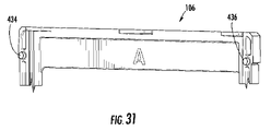
- FIG. 31 is a schematic of a top portion of the first side of the third rectangular ring-shaped frame member of FIG. 29 ;
- FIG. 32 is a schematic of a second side of the third rectangular ring-shaped frame member of FIG. 29 ;
- FIG. 33 is a schematic of a bottom portion of the second side of the third rectangular ring-shaped frame member of FIG. 32 ;
- FIG. 34 is a schematic of a top portion of the second side of the third rectangular ring-shaped frame member of FIG. 21 ;
- FIG. 35 is a schematic of another battery cell assembly utilized in the battery module of FIG. 2 ;
- FIG. 36 is a schematic of a cooling manifold utilized in the battery module of FIG. 1 .
- the battery module 20 includes battery cell assemblies 30 , 32 , 34 , 36 , 38 , 40 , 42 , 44 , heat exchangers 50 , 52 , 54 , 56 , side plates 60 , 62 , 64 , 66 , coupling plates 70 , 72 , an interconnect assembly 74 , a cover 76 , and cooling manifolds 78 , 80 .
- a battery cell assembly is defined as a housing having a battery cell therein.
- a battery module is defined as at least two battery cell assemblies coupled together.
- the battery cell assemblies 30 , 32 , 34 , 36 , 38 , 40 , 42 , 44 are electrically coupled together utilizing the interconnect assembly 74 .
- the interconnect assembly 74 electrically couples together electrical terminals from the battery cell assemblies in a desired configuration to provide an electrical current and voltage therefrom.
- the heat exchangers 50 , 52 , 54 , 56 receive a fluid from the cooling manifold 78 to cool the battery cell assemblies.
- the heated fluid from the heat exchangers 50 , 52 , 54 , 56 is received by the cooling manifold 80 .
- the side plates 60 , 62 , 64 , 66 are coupled to the battery cell assemblies to provide additional support for the battery cell assemblies.
- the coupling plates 70 , 72 are provided to engage the side plates 64 , 66 to provide additional support for the battery cell assemblies.
- the cover plate 76 is provided to cover the interconnect assembly 74 .
- the battery cell assembly 32 includes a rectangular ring-shaped frame member 90 , a battery cell 92 , a securement ring-shaped member 94 , a battery cell 96 , a rectangular ring-shaped frame member 98 , a heat exchanger 100 , a securement ring-shaped member 102 , a battery cell 104 , and a rectangular ring-shaped frame member 106 .
- An advantage of the battery cell assembly 32 is that the assembly 32 is packaged such that a single heat exchanger 100 can cool the battery cells 92 , 96 , 104 to maintain the battery cells at a desired temperature. Further, the rectangular ring-shaped frame members 90 , 98 , 106 have alignment-coupling features for easily coupling the frame members 90 , 98 , 106 together while preventing incorrect alignment and placement of the frame members 90 , 98 , 106 relative to one another.
- the rectangular ring-shaped frame member 90 is configured to be coupled to the rectangular ring-shaped frame member 98 for holding the battery cell 92 , the securement ring-shaped member 94 , and the battery cell 96 therebetween.
- the rectangular ring-shaped frame member 90 includes a side 110 and an opposite side 112 .
- the frame member 90 includes side walls 114 , 116 , a lower wall 118 , and an upper wall 120 .
- the side walls 114 , 116 are disposed apart from one another and are substantially parallel to one another.
- the lower wall 118 extends between the side walls 114 , 116 .
- the upper wall 120 extends between the side walls 114 , 116 .
- the side walls 114 , 116 , the lower wall 118 , and the upper wall 120 define an open region 122 therebetween.
- the lower wall 118 includes alignment-coupling features 130 , 132 disposed on opposite ends of the lower wall 118 .
- the upper wall 120 includes alignment-coupling features 134 , 136 disposed on opposite ends of the upper wall 120 .
- the alignment-coupling features 130 , 132 , 134 , 136 are configured to couple and align with specific alignment-coupling features on the battery cell assembly 30 shown in FIG. 2 .
- the side walls 114 , 116 , the lower wall 118 , and the upper wall 120 define a ledge portion 139 .
- the side walls 114 , 116 have horizontal grooves 137 , 138 for receiving a portion of an inlet port and an outlet port, respectively, of the heat exchanger 50 thereon shown in FIG. 2 .
- the lower wall 118 includes alignment-coupling features 140 , 142 disposed on opposite ends of the lower wall 118 .
- the upper wall 120 includes alignment-coupling features 144 , 146 disposed on opposite ends of the upper wall 120 .
- the alignment-coupling features 140 , 142 , 144 , 146 are configured to couple and align with alignment-coupling features 232 , 230 , 236 , 234 , respectively, on the battery cell assembly 98 shown in FIG. 18 .
- the side 112 of the frame member 98 includes a side coupling identifier “B” which indicates the side 112 is to be coupled to the side 200 of the frame member 98 having the side coupling identifier “B.”
- the battery cell 92 is provided to output an operational voltage between the electrical terminals 164 , 166 .
- the battery cell 92 includes a body portion 160 and a peripheral lip portion 162 extending around the body portion 160 , and electrical terminals 164 , 166 extending from the body portion 160 .
- the battery cell 92 is generally rectangular-shaped and includes a side 156 and a side 158 opposite the side 156 .
- the battery cell 92 is a lithium battery cell.
- the battery cell 92 can comprise other types of battery cells known to those skilled in the art.
- the size of the peripheral lip portion 162 is smaller than a size of the rectangular ring-shaped frame member 90 such that the frame member 90 covers the peripheral lip portion 162 of the battery cell 92 .
- the battery cell 92 is disposed between the frame member 90 and a portion of the securement ring-shaped member 94 and the battery cell 96 .
- the securement ring-shaped member 94 is provided to further secure the battery cells 92 , 96 between the rectangular ring-shaped members 90 , 98 .
- the securement ring-shaped member 94 includes a side 180 and an opposite side 182 . Further, the securement ring-shaped member 94 includes side walls 186 , 188 disposed away from one another and substantially parallel to one another. Further, the securement ring-shaped member 94 includes an upper wall 190 and a lower wall 192 extending between the side walls 186 , 188 .
- the side walls 186 , 188 , the upper wall 190 and the lower wall 192 define an open region 193 therebetween.
- An outer peripheral size of the securement ring-shaped member 94 is smaller than an outer peripheral size of the rectangular ring-shaped frame member 90 and smaller than an outer peripheral size of the rectangular ring-shaped frame member 98 .
- the securement ring-shaped member 94 is disposed between the peripheral lip portions of the battery cells 92 , 96 to further support the battery cells 92 , 96 .
- the battery cell 96 is disposed between the rectangular ring-shaped frame member 98 and both a portion of the battery cell 92 and the securement ring-shaped member 94 .
- the structure of the battery cell 96 is substantially similar to the battery cell 92 .
- the rectangular ring-shaped frame member 98 is configured to be coupled to the rectangular ring-shaped frame member 90 for holding the battery cell 92 , the securement ring-shaped member 94 , and the battery cell 96 therebetween. Further, the rectangular ring-shaped frame member 98 is provided to couple to the rectangular ring-shaped frame member 106 for holding the heat exchanger 100 , the securement ring-shaped member 102 , and the battery cell 104 therebetween.
- the rectangular ring-shaped frame member 98 includes a side 200 and an opposite side 202 .
- the frame member 98 includes side walls 214 , 216 , a lower wall 218 , and an upper wall 220 .
- the side walls 214 , 216 are disposed apart from one another and are substantially parallel to one another.
- the lower wall 218 extends between the side walls 214 , 216 .
- the upper wall 220 extends between the side walls 214 , 216 .
- the side walls 214 , 216 , the lower wall 218 , and the upper wall 220 define an open region 222 therebetween.
- the lower wall 218 includes alignment-coupling features 230 , 232 disposed on opposite ends of the lower wall 218 .
- the upper wall 220 includes alignment-coupling features 234 , 236 disposed on opposite ends of the upper wall 220 .
- the alignment-coupling features 230 , 232 , 234 , 236 are configured to couple and align with alignment-coupling features 142 , 140 , 146 , 144 , respectively, on the side 112 of the rectangular ring-shaped frame member 90 shown in FIG. 11 .
- the side 200 of the frame member 98 includes a side coupling identifier “B” which indicates the side 200 is to be coupled to the side 112 of the frame member 90 having the side coupling identifier “B.”
- the lower wall 218 includes alignment-coupling features 240 , 242 disposed on opposite ends of the lower wall 218 .
- the upper wall 220 includes alignment-coupling features 244 , 246 disposed on opposite ends of the upper wall 220 .
- the alignment-coupling features 240 , 242 , 244 , 246 are configured to couple and align with alignment-coupling features 432 , 430 , 436 , 434 , respectively, on the battery cell assembly 106 shown in FIG. 29 .
- the side walls 214 , 216 , the lower wall 218 , and the upper wall 220 define a ledge portion 250 for receiving a portion of the heat exchanger 100 thereon.
- the side walls 114 , 116 have horizontal grooves 247 , 248 , respectively, for receiving a portion of an outlet port and an inlet port, respectively, of the heat exchanger 100 thereon.
- the side 202 of the frame member 98 includes a side coupling identifier “A” that indicates the side 202 is to be coupled to the side 400 of the frame member 106 having the side coupling identifier “A.”
- the heat exchanger 100 is configured to cool the battery cells 92 , 96 and 104 to maintain the battery cells at a desired temperature.
- the heat exchanger 100 is disposed between (i) a portion of the battery cell 96 and the rectangular ring-shaped frame member 98 , and (ii) a portion of the battery cell 104 and the securement ring-shaped member 102 .
- the heat exchanger 100 includes a side 256 and an opposite side 258 .
- the heat exchanger 100 further includes a housing 260 , an inlet port 262 , and an outlet port 264 .
- the housing 260 defines a flow path 266 that extends from the inlet port 262 to the outlet port 264 .
- fluid from the cooling manifold 78 flows through the inlet port 262 into the heat exchanger 100 . Thereafter, the fluid flows through the flow path 266 to the outlet port 264 . While flowing through the flow path 266 , the fluid extracts heat energy from the battery cells 92 , 96 , 104 to cool the battery cells. From the outlet port 264 , the heated fluid flows to the cooling manifold 80 .
- the securement ring-shaped member 102 is provided to further secure the heat exchanger 100 and the battery cell 104 between the rectangular ring-shaped members 90 , 106 .
- the securement ring-shaped member 102 includes a side 280 and an opposite side 282 .
- the securement ring-shaped member 102 includes side walls 286 , 288 disposed away from one another and substantially parallel to one another.
- the securement ring-shaped member 102 includes an upper wall 290 and a lower wall 292 extending between the side walls 286 , 288 .
- the side walls 286 , 288 , the upper wall 290 and the lower wall 292 define an open region 293 therebetween.
- the side walls 286 , 288 on the side 280 include grooves 300 , 302 , respectively, for receiving the inlet port 262 and the outlet port 264 , respectively of the heat exchanger 100 thereon.
- An outer peripheral size of the securement ring-shaped member 102 is smaller than an outer peripheral size of the rectangular ring-shaped frame member 98 and smaller than an outer peripheral size of the rectangular ring-shaped frame member 106 . Referring to FIGS. 6 and 7 , the securement ring-shaped member 102 is disposed between the rectangular ring-shaped frame member 98 and a peripheral lip portion of the battery cell 104 .
- the battery cell 104 is disposed between the rectangular ring-shaped frame member 106 and both a portion of the heat exchanger 100 and the securement ring-shaped member 102 .
- the structure of the battery cell 104 is substantially similar to the battery cell 92 .
- the rectangular ring-shaped frame member 106 is configured to be coupled to the rectangular ring-shaped frame member 98 for holding the heat exchanger 100 , the securement ring-shaped member 102 , and the battery cell 104 therebetween. Further, the rectangular ring-shaped frame member 106 is provided to couple to the battery cell assembly 34 shown in FIG. 35 as will be explained in greater detail below.
- the rectangular ring-shaped frame member 106 includes a side 400 and an opposite side 402 . Further, in an exemplary embodiment, the frame member 106 includes side walls 414 , 416 , a lower wall 418 , and an upper wall 420 .
- the side walls 414 , 416 are disposed apart from one another and are substantially parallel to one another.
- the lower wall 418 extends between the side walls 414 , 416 .
- the upper wall 420 extends between the side walls 414 , 416 .
- the side walls 414 , 416 , the lower wall 418 , and the upper wall 420 define an open region 422 therebetween.
- the side walls 414 , 416 , the lower wall 418 , and the upper wall 420 define a ledge portion 238 .
- the lower wall 418 includes alignment-coupling features 430 , 432 disposed on opposite ends of the lower wall 418 .
- the upper wall 420 includes alignment-coupling features 434 , 436 disposed on opposite ends of the upper wall 420 .
- the alignment-coupling features 430 , 432 , 434 , 436 are configured to couple and align with alignment-coupling features 242 , 240 , 246 , 244 , respectively, on the side 202 of the rectangular ring-shaped frame member 98 shown in FIG. 21 .
- the side 400 of the frame member 106 includes a side coupling identifier “A” that indicates the side 400 is to be coupled to the side 202 of the frame member 98 having the side coupling identifier “A.”
- the lower wall 418 includes alignment-coupling features 440 , 442 disposed on opposite ends of the lower wall 418 .
- the upper wall 420 includes alignment-coupling features 444 , 446 disposed on opposite ends of the upper wall 420 .
- the alignment-coupling features 440 , 442 , 444 , 446 are configured to couple and align with alignment-coupling features 532 , 530 , 536 , 534 , respectively, on the battery cell assembly 34 shown in FIG. 34 .
- the side 402 of the frame member 106 includes a side coupling identifier “C” which indicates the side 402 is to be coupled to a side of the frame member 450 having the side coupling identifier “C.”
- each of the rectangular ring-shaped frame members 90 , 98 , 106 have a different configuration from one another such that only a specific side of each of the rectangular ring-shaped members 90 , 98 , 106 can align and couple with another specific side of one of the other rectangular ring-shaped frame members 90 , 98 , 106 .
- the battery cell assembly 34 is configured to be coupled to the battery cell assembly 32 in the battery module 20 .
- the battery cell assembly 34 includes rectangular ring-shaped frame members 450 , 452 , 454 . Further, the battery cell assembly 34 includes two battery cells, two securement frame members and an heat exchanger contained within the frame members 450 , 452 , 454 .
- the rectangular ring-shaped frame member 450 includes side walls 514 , 516 , a lower wall 518 , and an upper wall 520 .
- the side walls 514 , 516 are disposed apart from one another and are substantially parallel to one another.
- the lower wall 518 extends between the side walls 514 , 516 .
- the upper wall 520 extends between the side walls 514 , 516 .
- the side walls 514 , 516 , the lower wall 518 , and the upper wall 520 define an open region therebetween.
- the lower wall 518 includes alignment-coupling features 530 , 532 disposed on opposite ends of the lower wall 518 .
- the upper wall 520 includes alignment-coupling features 534 , 536 disposed on opposite ends of the upper wall 520 .
- the alignment-coupling features 530 , 532 , 534 , 536 are configured to couple and align with alignment-coupling features 442 , 440 , 446 , 444 , respectively, on the side 402 of the rectangular ring-shaped frame member 106 shown in FIG. 32 .
- the cooling manifold 78 is configured to route a fluid to inlet ports on the heat exchangers 50 , 52 , 54 , 56 and to the heat exchangers in the battery cell assemblies 30 , 32 , 34 , 36 , 40 , 42 , 44 .
- the cooling manifold 78 includes a tubular member 600 , an inlet port 602 , and outlet ports 604 , 606 , 608 , 610 , 612 , 614 , 616 , 618 , 620 , 622 , 624 , 626 , 628 , 630 , 632 .
- the inlet port 602 is provided to receive fluid from a fluid reservoir into the tubular member 600 .
- the tubular member 600 routes the fluid through the outlet ports 604 , 606 , 608 , 610 , 612 , 614 , 616 , 618 , 620 , 622 , 624 , 626 , 628 , 630 , 632 to the respective inlet ports of the heat exchangers in the battery module 20 .
- the cooling manifold 78 can be constructed from rubber or a rubber compound. Of course, in an alternative embodiment, the cooling manifold 78 can be constructed from other materials such as plastics, metals, or ceramics.
- the cooling manifold 80 has a substantially similar construction as the cooling manifold 78 .
- the cooling manifold 80 is configured to receive heated fluid from outlet ports of the heat exchangers in the battery module 20 and to route the heated fluid to a fluid reservoir.
- the battery module 20 has a battery cell assembly that provides a substantial advantage over other batteries.
- the battery cell assembly provides a technical effect of cooling battery cells disposed on two sides of a heat exchanger to maintain the battery cells at a desired temperature.
Abstract
Description
Claims (11)
Priority Applications (6)
| Application Number | Priority Date | Filing Date | Title |
|---|---|---|---|
| US12/164,780 US8067111B2 (en) | 2008-06-30 | 2008-06-30 | Battery module having battery cell assembly with heat exchanger |
| KR1020080073272A KR101145732B1 (en) | 2008-06-30 | 2008-07-26 | Battery Module Having Battery Cell Assembly with Heat Exchanger |
| PCT/KR2009/003430 WO2010002139A2 (en) | 2008-06-30 | 2009-06-25 | Battery module comprising battery cell assembly with heat exchanger |
| EP09773675.5A EP2293377B1 (en) | 2008-06-30 | 2009-06-25 | Battery module comprising battery cell assembly with heat exchanger |
| CN2009801221263A CN102067374B (en) | 2008-06-30 | 2009-06-25 | Battery module comprising battery cell assembly with heat exchanger |
| JP2011516131A JP5456774B2 (en) | 2008-06-30 | 2009-06-25 | Battery module having a battery cell assembly including a heat exchanger |
Applications Claiming Priority (1)
| Application Number | Priority Date | Filing Date | Title |
|---|---|---|---|
| US12/164,780 US8067111B2 (en) | 2008-06-30 | 2008-06-30 | Battery module having battery cell assembly with heat exchanger |
Publications (2)
| Publication Number | Publication Date |
|---|---|
| US20090325053A1 US20090325053A1 (en) | 2009-12-31 |
| US8067111B2 true US8067111B2 (en) | 2011-11-29 |
Family
ID=41447858
Family Applications (1)
| Application Number | Title | Priority Date | Filing Date |
|---|---|---|---|
| US12/164,780 Active 2030-02-14 US8067111B2 (en) | 2008-06-30 | 2008-06-30 | Battery module having battery cell assembly with heat exchanger |
Country Status (6)
| Country | Link |
|---|---|
| US (1) | US8067111B2 (en) |
| EP (1) | EP2293377B1 (en) |
| JP (1) | JP5456774B2 (en) |
| KR (1) | KR101145732B1 (en) |
| CN (1) | CN102067374B (en) |
| WO (1) | WO2010002139A2 (en) |
Cited By (31)
| Publication number | Priority date | Publication date | Assignee | Title |
|---|---|---|---|---|
| US20110256446A1 (en) * | 2010-04-17 | 2011-10-20 | Lg Chem, Ltd. | Battery cell assemblies |
| US20120188714A1 (en) * | 2009-04-24 | 2012-07-26 | Von Borck Felix | Battery management system |
| US8399119B2 (en) | 2009-08-28 | 2013-03-19 | Lg Chem, Ltd. | Battery module and method for cooling the battery module |
| US8399118B2 (en) | 2009-07-29 | 2013-03-19 | Lg Chem, Ltd. | Battery module and method for cooling the battery module |
| US8403030B2 (en) | 2009-04-30 | 2013-03-26 | Lg Chem, Ltd. | Cooling manifold |
| US8486552B2 (en) | 2008-06-30 | 2013-07-16 | Lg Chem, Ltd. | Battery module having cooling manifold with ported screws and method for cooling the battery module |
| US8663829B2 (en) | 2009-04-30 | 2014-03-04 | Lg Chem, Ltd. | Battery systems, battery modules, and method for cooling a battery module |
| US8662153B2 (en) | 2010-10-04 | 2014-03-04 | Lg Chem, Ltd. | Battery cell assembly, heat exchanger, and method for manufacturing the heat exchanger |
| US20140113169A1 (en) * | 2010-07-12 | 2014-04-24 | GM Global Technology Operations LLC | Support feature for joining of battery cell tabs |
| US8852783B2 (en) | 2013-02-13 | 2014-10-07 | Lg Chem, Ltd. | Battery cell assembly and method for manufacturing the battery cell assembly |
| US8852781B2 (en) | 2012-05-19 | 2014-10-07 | Lg Chem, Ltd. | Battery cell assembly and method for manufacturing a cooling fin for the battery cell assembly |
| US9083066B2 (en) | 2012-11-27 | 2015-07-14 | Lg Chem, Ltd. | Battery system and method for cooling a battery cell assembly |
| US9105950B2 (en) | 2012-03-29 | 2015-08-11 | Lg Chem, Ltd. | Battery system having an evaporative cooling member with a plate portion and a method for cooling the battery system |
| US9184424B2 (en) | 2013-07-08 | 2015-11-10 | Lg Chem, Ltd. | Battery assembly |
| US9257732B2 (en) | 2013-10-22 | 2016-02-09 | Lg Chem, Ltd. | Battery cell assembly |
| US9306199B2 (en) | 2012-08-16 | 2016-04-05 | Lg Chem, Ltd. | Battery module and method for assembling the battery module |
| US9337456B2 (en) | 2009-04-20 | 2016-05-10 | Lg Chem, Ltd. | Frame member, frame assembly and battery cell assembly made therefrom and methods of making the same |
| US9379420B2 (en) | 2012-03-29 | 2016-06-28 | Lg Chem, Ltd. | Battery system and method for cooling the battery system |
| US9412980B2 (en) | 2014-10-17 | 2016-08-09 | Lg Chem, Ltd. | Battery cell assembly |
| US9444124B2 (en) | 2014-01-23 | 2016-09-13 | Lg Chem, Ltd. | Battery cell assembly and method for coupling a cooling fin to first and second cooling manifolds |
| US9484559B2 (en) | 2014-10-10 | 2016-11-01 | Lg Chem, Ltd. | Battery cell assembly |
| US9605914B2 (en) | 2012-03-29 | 2017-03-28 | Lg Chem, Ltd. | Battery system and method of assembling the battery system |
| US9608245B2 (en) | 2014-09-30 | 2017-03-28 | Johnson Controls Technology Company | System for providing structural integrity of a battery module |
| US9627724B2 (en) | 2014-12-04 | 2017-04-18 | Lg Chem, Ltd. | Battery pack having a cooling plate assembly |
| US9647292B2 (en) | 2013-04-12 | 2017-05-09 | Lg Chem, Ltd. | Battery cell assembly and method for manufacturing a cooling fin for the battery cell assembly |
| US9759495B2 (en) | 2008-06-30 | 2017-09-12 | Lg Chem, Ltd. | Battery cell assembly having heat exchanger with serpentine flow path |
| US9786894B2 (en) | 2014-11-03 | 2017-10-10 | Lg Chem, Ltd. | Battery pack |
| US10084218B2 (en) | 2014-05-09 | 2018-09-25 | Lg Chem, Ltd. | Battery pack and method of assembling the battery pack |
| US10770762B2 (en) | 2014-05-09 | 2020-09-08 | Lg Chem, Ltd. | Battery module and method of assembling the battery module |
| US11121426B2 (en) | 2017-11-30 | 2021-09-14 | William Koetting | Battery module including nodal cell compression and heat rejection |
| US11211649B2 (en) | 2017-03-30 | 2021-12-28 | Samsung Sdi Co., Ltd. | Battery module |
Families Citing this family (29)
| Publication number | Priority date | Publication date | Assignee | Title |
|---|---|---|---|---|
| KR100880388B1 (en) * | 2005-04-20 | 2009-01-23 | 주식회사 엘지화학 | Housing Member For Battery Module |
| KR101029021B1 (en) * | 2005-12-02 | 2011-04-14 | 주식회사 엘지화학 | Battery Module of High Cooling Efficiency |
| US8628872B2 (en) * | 2008-01-18 | 2014-01-14 | Lg Chem, Ltd. | Battery cell assembly and method for assembling the battery cell assembly |
| US9140501B2 (en) * | 2008-06-30 | 2015-09-22 | Lg Chem, Ltd. | Battery module having a rubber cooling manifold |
| US8663828B2 (en) | 2009-04-30 | 2014-03-04 | Lg Chem, Ltd. | Battery systems, battery module, and method for cooling the battery module |
| US8852778B2 (en) | 2009-04-30 | 2014-10-07 | Lg Chem, Ltd. | Battery systems, battery modules, and method for cooling a battery module |
| US8268472B2 (en) * | 2009-09-30 | 2012-09-18 | Bright Automotive, Inc. | Battery cooling apparatus for electric vehicle |
| KR101247909B1 (en) * | 2010-02-17 | 2013-03-26 | 가부시키가이샤 히타치세이사쿠쇼 | Battery pack system |
| US8383260B2 (en) * | 2010-02-26 | 2013-02-26 | GM Global Technology Operations LLC | U-formed cooling plate with solid fins for lithium pouch cells |
| US8469404B2 (en) | 2010-08-23 | 2013-06-25 | Lg Chem, Ltd. | Connecting assembly |
| US8353315B2 (en) | 2010-08-23 | 2013-01-15 | Lg Chem, Ltd. | End cap |
| US8920956B2 (en) | 2010-08-23 | 2014-12-30 | Lg Chem, Ltd. | Battery system and manifold assembly having a manifold member and a connecting fitting |
| US8758922B2 (en) | 2010-08-23 | 2014-06-24 | Lg Chem, Ltd. | Battery system and manifold assembly with two manifold members removably coupled together |
| US9005799B2 (en) | 2010-08-25 | 2015-04-14 | Lg Chem, Ltd. | Battery module and methods for bonding cell terminals of battery cells together |
| JP6004402B2 (en) * | 2011-03-18 | 2016-10-05 | デーナ、カナダ、コーパレイシャン | Battery cell cooler, apparatus, and method |
| US8288031B1 (en) | 2011-03-28 | 2012-10-16 | Lg Chem, Ltd. | Battery disconnect unit and method of assembling the battery disconnect unit |
| US9178192B2 (en) | 2011-05-13 | 2015-11-03 | Lg Chem, Ltd. | Battery module and method for manufacturing the battery module |
| US9496544B2 (en) | 2011-07-28 | 2016-11-15 | Lg Chem. Ltd. | Battery modules having interconnect members with vibration dampening portions |
| US9050898B2 (en) * | 2011-10-19 | 2015-06-09 | GM Global Technology Operations LLC | Wave fin battery module |
| JP5917899B2 (en) * | 2011-11-29 | 2016-05-18 | 日産自動車株式会社 | Thin battery and method of manufacturing thin battery |
| US8977510B2 (en) * | 2011-12-15 | 2015-03-10 | Lg Chem, Ltd. | System and method for determining charging and discharging power levels for a battery pack |
| US8974934B2 (en) * | 2012-08-16 | 2015-03-10 | Lg Chem, Ltd. | Battery module |
| KR102021150B1 (en) | 2012-12-26 | 2019-09-11 | 현대모비스 주식회사 | Battery cell module assembly for vehicle |
| US9387773B2 (en) | 2012-12-30 | 2016-07-12 | Lg Chem, Ltd. | System and method for derating a power limit associated with a battery pack |
| JP5610007B2 (en) * | 2013-02-15 | 2014-10-22 | 株式会社豊田自動織機 | Battery module |
| US9972869B2 (en) * | 2014-01-31 | 2018-05-15 | Lg Chem, Ltd. | Battery cell assembly having improved thermal sensing capability |
| KR101769577B1 (en) * | 2014-05-07 | 2017-08-18 | 주식회사 엘지화학 | Battery Pack Having Hold Down Bracket |
| KR102321512B1 (en) * | 2014-09-11 | 2021-11-04 | 현대모비스 주식회사 | Water-cooled battery cooling apparatus using water-cooled battery module |
| MX2022000389A (en) * | 2019-07-09 | 2023-02-07 | Otsuka Medical Devices Co Ltd | Drug-eluting stent. |
Citations (80)
| Publication number | Priority date | Publication date | Assignee | Title |
|---|---|---|---|---|
| US4390841A (en) | 1980-10-14 | 1983-06-28 | Purdue Research Foundation | Monitoring apparatus and method for battery power supply |
| US4396689A (en) | 1981-06-01 | 1983-08-02 | Exxon Research And Engineering Co. | Separator-spacer for electrochemical systems |
| US5322745A (en) * | 1992-11-10 | 1994-06-21 | Matsushita Electric Industrial Co., Ltd. | Storage battery system |
| US5356735A (en) * | 1993-05-10 | 1994-10-18 | General Motors Corporation | Heated/cooled battery |
| US5364711A (en) | 1992-04-01 | 1994-11-15 | Kabushiki Kaisha Toshiba | Fuel cell |
| US5487955A (en) | 1994-03-15 | 1996-01-30 | Electric Fuel (E.F.L.) Ltd. | Cooled zinc-oxygen battery |
| US5606242A (en) | 1994-10-04 | 1997-02-25 | Duracell, Inc. | Smart battery algorithm for reporting battery parameters to an external device |
| US5652502A (en) | 1994-11-10 | 1997-07-29 | Duracell, Inc. | Battery pack having a processor controlled battery operating system |
| US5658682A (en) | 1992-12-11 | 1997-08-19 | Honda Giken Kogyo Kabushiki Kaisha | Process for detecting remaining capacity of battery |
| US5825155A (en) | 1993-08-09 | 1998-10-20 | Kabushiki Kaisha Toshiba | Battery set structure and charge/ discharge control apparatus for lithium-ion battery |
| US5982403A (en) | 1992-11-30 | 1999-11-09 | Ricoh Company, Ltd. | Potential estimating apparatus using a plurality of neural networks for carrying out an electrographic process |
| US6016047A (en) | 1996-11-21 | 2000-01-18 | U.S. Philips Corporation | Battery management system and battery simulator |
| US6353815B1 (en) | 1998-11-04 | 2002-03-05 | The United States Of America As Represented By The United States Department Of Energy | Statistically qualified neuro-analytic failure detection method and system |
| US6362598B2 (en) | 2000-04-29 | 2002-03-26 | Vb Autobatterie Gmbh | Method for determining the state of charge and loading capacity of an electrical storage battery |
| US6441586B1 (en) | 2001-03-23 | 2002-08-27 | General Motors Corporation | State of charge prediction method and apparatus for a battery |
| JP2002319383A (en) | 2001-04-23 | 2002-10-31 | Toyota Motor Corp | Battery module |
| US6515454B2 (en) | 2001-02-13 | 2003-02-04 | Robert Bosch Gmbh | Method and system for determining the capacity of a battery |
| US6534954B1 (en) | 2002-01-10 | 2003-03-18 | Compact Power Inc. | Method and apparatus for a battery state of charge estimator |
| US6563318B2 (en) | 2000-05-23 | 2003-05-13 | Canon Kabushiki Kaisha | Detecting method for detecting internal state of a rechargeable battery, detecting device for practicing said detecting method, and instrument provided with said detecting device |
| US20030184307A1 (en) | 2002-02-19 | 2003-10-02 | Kozlowski James D. | Model-based predictive diagnostic tool for primary and secondary batteries |
| US6724172B2 (en) | 2002-06-26 | 2004-04-20 | Hyundai Motor Company | Method for determining a maximum charge current and a maximum discharge current of a battery |
| US6821671B2 (en) | 2002-03-01 | 2004-11-23 | Lg Chem, Ltd. | Method and apparatus for cooling and positioning prismatic battery cells |
| US6829562B2 (en) | 2001-02-13 | 2004-12-07 | Robert Bosch Gmbh | Method and device for state sensing of technical systems such as energy stores |
| US6832171B2 (en) | 2002-12-29 | 2004-12-14 | Texas Instruments Incorporated | Circuit and method for determining battery impedance increase with aging |
| US6876175B2 (en) | 2001-06-29 | 2005-04-05 | Robert Bosch Gmbh | Methods for determining the charge state and/or the power capacity of charge store |
| US6892148B2 (en) | 2002-12-29 | 2005-05-10 | Texas Instruments Incorporated | Circuit and method for measurement of battery capacity fade |
| US20050100786A1 (en) | 2003-09-19 | 2005-05-12 | Ryu Duk H. | Nonaqueous lithium secondary battery with cyclability and/or high temperature safety improved |
| US20050127874A1 (en) | 2003-12-12 | 2005-06-16 | Myoungho Lim | Method and apparatus for multiple battery cell management |
| US6927554B2 (en) | 2003-08-28 | 2005-08-09 | General Motors Corporation | Simple optimal estimator for PbA state of charge |
| US20050194936A1 (en) | 2003-12-18 | 2005-09-08 | Il Cho | Apparatus and method for estimating state of charge of battery using neural network |
| US6943528B2 (en) | 2000-11-17 | 2005-09-13 | Robert Bosch Gmbh | Method and arrangement for determination of the state of charge of a battery |
| US6967466B2 (en) | 2002-08-31 | 2005-11-22 | Vb Autobatterie Gmbh | Method for determining the amount of charge which can be drawn on a storage battery, and monitoring device for a storage battery |
| US7012434B2 (en) | 2002-07-13 | 2006-03-14 | Vb Autobatterie Gmbh | Method for determining the amount of charge which can be drawn from a storage battery and monitoring device |
| US7039534B1 (en) | 2003-11-03 | 2006-05-02 | Ryno Ronald A | Charging monitoring systems |
| US20060097698A1 (en) | 2004-11-11 | 2006-05-11 | Plett Gregory L | Method and system for cell equalization using state of charge |
| US20060100833A1 (en) | 2004-11-11 | 2006-05-11 | Plett Gregory L | State and parameter estimation for an electrochemical cell |
| US20060111854A1 (en) | 2004-11-23 | 2006-05-25 | Plett Gregory L | Method and system for battery parameter estimation |
| US20060111870A1 (en) | 2004-11-23 | 2006-05-25 | Plett Gregory L | Method and system for joint battery state and parameter estimation |
| US7061246B2 (en) | 2001-12-06 | 2006-06-13 | Johnson Controls Technology Company | Battery monitoring system and method |
| US7072871B1 (en) | 2001-08-22 | 2006-07-04 | Cadex Electronics Inc. | Fuzzy logic method and apparatus for battery state of health determination |
| US7074517B2 (en) | 2002-07-30 | 2006-07-11 | Nissan Motor Co., Ltd. | Battery module |
| US7098665B2 (en) | 2002-11-13 | 2006-08-29 | Vb Autobatterie Gmbh | Method for prediction of the internal resistance of an energy storage battery, and a monitoring device for energy storage batteries |
| US7109685B2 (en) | 2003-09-17 | 2006-09-19 | General Motors Corporation | Method for estimating states and parameters of an electrochemical cell |
| WO2006101343A1 (en) * | 2005-03-23 | 2006-09-28 | Sk Energy Co., Ltd. | Structure of layering unit cells for high power lithium polymer battery |
| US20060214633A1 (en) | 2005-03-25 | 2006-09-28 | Kyu-Woong Cho | Rechargeable battery module |
| US20060234119A1 (en) * | 2005-04-14 | 2006-10-19 | Kruger Duane D | Apparatus and method for securing battery cell packs |
| US7126312B2 (en) | 2004-07-28 | 2006-10-24 | Enerdel, Inc. | Method and apparatus for balancing multi-cell lithium battery systems |
| US20060286450A1 (en) * | 2005-06-03 | 2006-12-21 | Junill Yoon | Secondary battery of novel structure and battery pack having the same |
| US20070035307A1 (en) | 2003-01-25 | 2007-02-15 | Eberhard Schoch | State variable and parameter estimator comprising several partial models for an electrical energy storage device |
| US20070037051A1 (en) | 2005-08-10 | 2007-02-15 | Kim Tae-Yong | Battery module with improved cell barrier between unit cells |
| US20070046292A1 (en) | 2005-08-23 | 2007-03-01 | Plett Gregory L | System and method for estimating a state vector associated with a battery |
| US7197487B2 (en) | 2005-03-16 | 2007-03-27 | Lg Chem, Ltd. | Apparatus and method for estimating battery state of charge |
| US20070072066A1 (en) * | 2004-12-24 | 2007-03-29 | Junill Yoon | Battery cartridge for novel structure and open type battery module containing the same |
| US7199557B2 (en) | 2003-07-01 | 2007-04-03 | Eaton Power Quality Company | Apparatus, methods and computer program products for estimation of battery reserve life using adaptively modified state of health indicator-based reserve life models |
| US20070103120A1 (en) | 2005-11-10 | 2007-05-10 | Plett Gregory L | System, method, and article of manufacture for determining an estimated battery state vector |
| US20070120533A1 (en) | 2005-11-30 | 2007-05-31 | Plett Gregory L | System, method, and article of manufacture for determining an estimated battery parameter vector |
| US7250741B2 (en) | 2003-08-13 | 2007-07-31 | Hyundai Motor Company | Method and system for calculating available power of a battery |
| US7253587B2 (en) | 2003-08-06 | 2007-08-07 | Vb Autobatterie Gmbh | Method for prediction of electrical characteristics of an electrochemical storage battery |
| US20070188143A1 (en) | 2006-02-09 | 2007-08-16 | Plett Gregory L | System, method, and article of manufacture for determining an estimated combined battery state-parameter vector |
| KR100765659B1 (en) | 2005-08-09 | 2007-10-10 | 현대자동차주식회사 | Fuel cell-stack structure for automobile |
| US20070236182A1 (en) | 2006-03-02 | 2007-10-11 | Plett Gregory L | System and method for determining both an estimated battery state vector and an estimated battery parameter vector |
| US7321220B2 (en) | 2003-11-20 | 2008-01-22 | Lg Chem, Ltd. | Method for calculating power capability of battery packs using advanced cell model predictive techniques |
| US7327147B2 (en) | 2004-02-04 | 2008-02-05 | Vb Autobatterie Gmbh & Co. Kgaa | Device and method for determining characteristic variables for batteries |
| US20080057392A1 (en) | 2006-08-31 | 2008-03-06 | Nissan Motor Co., Ltd. | Battery module |
| KR20080047641A (en) | 2006-11-27 | 2008-05-30 | 주식회사 엘지화학 | Power supply system having heat radiation-preventing structure |
| KR100889241B1 (en) | 2006-10-23 | 2009-03-17 | 주식회사 엘지화학 | Member of Connecting Electrode in Battery Module |
| KR100921346B1 (en) | 2006-09-25 | 2009-10-13 | 주식회사 엘지화학 | Mid-Large Battery Module and Battery Module Assembly |
| US20100086842A1 (en) | 2008-10-06 | 2010-04-08 | Lg Chem, Ltd. | Battery cell assembly and method for assembling the battery cell assembly |
| US20100209760A1 (en) * | 2007-05-10 | 2010-08-19 | Calsonic Kansei Corporation | Battery-cell module structure of battery |
| US7794868B2 (en) | 2005-12-02 | 2010-09-14 | Lg Chem, Ltd. | Battery module of high cooling efficiency |
| US20100266883A1 (en) | 2009-04-20 | 2010-10-21 | Lg Chem, Ltd. | Frame member, frame assembly and battery cell assembly made therefrom and methods of making the same |
| US20100279154A1 (en) | 2009-04-30 | 2010-11-04 | Lg Chem, Ltd. | Battery systems, battery modules, and method for cooling a battery module |
| US20100279153A1 (en) | 2009-04-30 | 2010-11-04 | Lg Chem, Ltd. | Battery systems, battery module, and method for cooling the battery module |
| US20100279152A1 (en) | 2009-04-30 | 2010-11-04 | Lg Chem, Ltd. | Battery systems, battery modules, and method for cooling a battery module |
| US20100275619A1 (en) | 2009-04-30 | 2010-11-04 | Lg Chem, Ltd. | Cooling system for a battery system and a method for cooling the battery system |
| US20100276132A1 (en) | 2009-04-30 | 2010-11-04 | Lg Chem, Ltd. | Cooling manifold and method for manufacturing the cooling manifold |
| US20110027640A1 (en) | 2009-07-29 | 2011-02-03 | Lg Chem, Ltd. | Battery module and method for cooling the battery module |
| US20110027625A1 (en) | 2009-07-29 | 2011-02-03 | Lg Chem, Ltd. | Battery module and method for cooling the battery module |
| US7883793B2 (en) * | 2008-06-30 | 2011-02-08 | Lg Chem, Ltd. | Battery module having battery cell assemblies with alignment-coupling features |
| US20110052959A1 (en) | 2009-08-28 | 2011-03-03 | Lg Chem, Ltd. | Battery module and method for cooling the battery module |
Family Cites Families (15)
| Publication number | Priority date | Publication date | Assignee | Title |
|---|---|---|---|---|
| JPH08111244A (en) * | 1994-10-12 | 1996-04-30 | Nissan Motor Co Ltd | Layer-built battery device |
| JP3451142B2 (en) * | 1994-11-18 | 2003-09-29 | 本田技研工業株式会社 | Battery assembly with temperature control mechanism |
| JPH08321329A (en) * | 1995-05-26 | 1996-12-03 | Sanyo Electric Co Ltd | Battery |
| JPH09199186A (en) * | 1996-01-22 | 1997-07-31 | Toyota Autom Loom Works Ltd | Storage battery cooling structure, storage battery module using storage battery cooling structure and storage battery cooling method |
| JP4534268B2 (en) * | 1999-02-05 | 2010-09-01 | トヨタ自動車株式会社 | Battery cooling plate and battery system |
| JP2001243993A (en) * | 2000-03-01 | 2001-09-07 | Hitachi Ltd | Secondary battery and its manufacturing method |
| JP4510467B2 (en) * | 2002-02-19 | 2010-07-21 | スリーエム イノベイティブ プロパティズ カンパニー | Temperature control apparatus and method for high energy electrochemical cells |
| JP4127060B2 (en) * | 2003-01-20 | 2008-07-30 | トヨタ自動車株式会社 | Lithium ion batteries for vehicles |
| JP2005349955A (en) * | 2004-06-10 | 2005-12-22 | Toyota Motor Corp | Cooling structure for power storage mechanism |
| KR100658715B1 (en) * | 2004-10-28 | 2006-12-15 | 삼성에스디아이 주식회사 | Secondary battery module |
| JP2006236826A (en) * | 2005-02-25 | 2006-09-07 | Toyota Motor Corp | Battery pack |
| JP4457931B2 (en) * | 2005-03-17 | 2010-04-28 | トヨタ自動車株式会社 | Battery module |
| KR100696669B1 (en) * | 2005-08-10 | 2007-03-19 | 삼성에스디아이 주식회사 | Secondary battery module |
| JP2007257843A (en) * | 2006-03-20 | 2007-10-04 | Autech Japan Inc | Vehicle battery pack |
| CN200976387Y (en) * | 2006-12-07 | 2007-11-14 | 比亚迪股份有限公司 | Batteries bag refrigerating mechanism |
-
2008
- 2008-06-30 US US12/164,780 patent/US8067111B2/en active Active
- 2008-07-26 KR KR1020080073272A patent/KR101145732B1/en active IP Right Grant
-
2009
- 2009-06-25 JP JP2011516131A patent/JP5456774B2/en active Active
- 2009-06-25 CN CN2009801221263A patent/CN102067374B/en active Active
- 2009-06-25 WO PCT/KR2009/003430 patent/WO2010002139A2/en active Application Filing
- 2009-06-25 EP EP09773675.5A patent/EP2293377B1/en active Active
Patent Citations (85)
| Publication number | Priority date | Publication date | Assignee | Title |
|---|---|---|---|---|
| US4390841A (en) | 1980-10-14 | 1983-06-28 | Purdue Research Foundation | Monitoring apparatus and method for battery power supply |
| US4396689A (en) | 1981-06-01 | 1983-08-02 | Exxon Research And Engineering Co. | Separator-spacer for electrochemical systems |
| US5364711A (en) | 1992-04-01 | 1994-11-15 | Kabushiki Kaisha Toshiba | Fuel cell |
| US5322745A (en) * | 1992-11-10 | 1994-06-21 | Matsushita Electric Industrial Co., Ltd. | Storage battery system |
| US5982403A (en) | 1992-11-30 | 1999-11-09 | Ricoh Company, Ltd. | Potential estimating apparatus using a plurality of neural networks for carrying out an electrographic process |
| US5658682A (en) | 1992-12-11 | 1997-08-19 | Honda Giken Kogyo Kabushiki Kaisha | Process for detecting remaining capacity of battery |
| US5356735A (en) * | 1993-05-10 | 1994-10-18 | General Motors Corporation | Heated/cooled battery |
| US5825155A (en) | 1993-08-09 | 1998-10-20 | Kabushiki Kaisha Toshiba | Battery set structure and charge/ discharge control apparatus for lithium-ion battery |
| US5487955A (en) | 1994-03-15 | 1996-01-30 | Electric Fuel (E.F.L.) Ltd. | Cooled zinc-oxygen battery |
| US5606242A (en) | 1994-10-04 | 1997-02-25 | Duracell, Inc. | Smart battery algorithm for reporting battery parameters to an external device |
| US5796239A (en) | 1994-11-10 | 1998-08-18 | Van Phuoc; Duong | Battery pack having a processor controlled battery operating system |
| US5652502A (en) | 1994-11-10 | 1997-07-29 | Duracell, Inc. | Battery pack having a processor controlled battery operating system |
| US6016047A (en) | 1996-11-21 | 2000-01-18 | U.S. Philips Corporation | Battery management system and battery simulator |
| US6353815B1 (en) | 1998-11-04 | 2002-03-05 | The United States Of America As Represented By The United States Department Of Energy | Statistically qualified neuro-analytic failure detection method and system |
| US6362598B2 (en) | 2000-04-29 | 2002-03-26 | Vb Autobatterie Gmbh | Method for determining the state of charge and loading capacity of an electrical storage battery |
| US6563318B2 (en) | 2000-05-23 | 2003-05-13 | Canon Kabushiki Kaisha | Detecting method for detecting internal state of a rechargeable battery, detecting device for practicing said detecting method, and instrument provided with said detecting device |
| US6943528B2 (en) | 2000-11-17 | 2005-09-13 | Robert Bosch Gmbh | Method and arrangement for determination of the state of charge of a battery |
| US6829562B2 (en) | 2001-02-13 | 2004-12-07 | Robert Bosch Gmbh | Method and device for state sensing of technical systems such as energy stores |
| US6515454B2 (en) | 2001-02-13 | 2003-02-04 | Robert Bosch Gmbh | Method and system for determining the capacity of a battery |
| US6441586B1 (en) | 2001-03-23 | 2002-08-27 | General Motors Corporation | State of charge prediction method and apparatus for a battery |
| JP2002319383A (en) | 2001-04-23 | 2002-10-31 | Toyota Motor Corp | Battery module |
| US6876175B2 (en) | 2001-06-29 | 2005-04-05 | Robert Bosch Gmbh | Methods for determining the charge state and/or the power capacity of charge store |
| US7072871B1 (en) | 2001-08-22 | 2006-07-04 | Cadex Electronics Inc. | Fuzzy logic method and apparatus for battery state of health determination |
| US7061246B2 (en) | 2001-12-06 | 2006-06-13 | Johnson Controls Technology Company | Battery monitoring system and method |
| US6534954B1 (en) | 2002-01-10 | 2003-03-18 | Compact Power Inc. | Method and apparatus for a battery state of charge estimator |
| US20030184307A1 (en) | 2002-02-19 | 2003-10-02 | Kozlowski James D. | Model-based predictive diagnostic tool for primary and secondary batteries |
| US6821671B2 (en) | 2002-03-01 | 2004-11-23 | Lg Chem, Ltd. | Method and apparatus for cooling and positioning prismatic battery cells |
| US6724172B2 (en) | 2002-06-26 | 2004-04-20 | Hyundai Motor Company | Method for determining a maximum charge current and a maximum discharge current of a battery |
| US7012434B2 (en) | 2002-07-13 | 2006-03-14 | Vb Autobatterie Gmbh | Method for determining the amount of charge which can be drawn from a storage battery and monitoring device |
| US7074517B2 (en) | 2002-07-30 | 2006-07-11 | Nissan Motor Co., Ltd. | Battery module |
| US6967466B2 (en) | 2002-08-31 | 2005-11-22 | Vb Autobatterie Gmbh | Method for determining the amount of charge which can be drawn on a storage battery, and monitoring device for a storage battery |
| US7098665B2 (en) | 2002-11-13 | 2006-08-29 | Vb Autobatterie Gmbh | Method for prediction of the internal resistance of an energy storage battery, and a monitoring device for energy storage batteries |
| US6892148B2 (en) | 2002-12-29 | 2005-05-10 | Texas Instruments Incorporated | Circuit and method for measurement of battery capacity fade |
| US6832171B2 (en) | 2002-12-29 | 2004-12-14 | Texas Instruments Incorporated | Circuit and method for determining battery impedance increase with aging |
| US20070035307A1 (en) | 2003-01-25 | 2007-02-15 | Eberhard Schoch | State variable and parameter estimator comprising several partial models for an electrical energy storage device |
| US7199557B2 (en) | 2003-07-01 | 2007-04-03 | Eaton Power Quality Company | Apparatus, methods and computer program products for estimation of battery reserve life using adaptively modified state of health indicator-based reserve life models |
| US7253587B2 (en) | 2003-08-06 | 2007-08-07 | Vb Autobatterie Gmbh | Method for prediction of electrical characteristics of an electrochemical storage battery |
| US7250741B2 (en) | 2003-08-13 | 2007-07-31 | Hyundai Motor Company | Method and system for calculating available power of a battery |
| US6927554B2 (en) | 2003-08-28 | 2005-08-09 | General Motors Corporation | Simple optimal estimator for PbA state of charge |
| US7109685B2 (en) | 2003-09-17 | 2006-09-19 | General Motors Corporation | Method for estimating states and parameters of an electrochemical cell |
| US20050100786A1 (en) | 2003-09-19 | 2005-05-12 | Ryu Duk H. | Nonaqueous lithium secondary battery with cyclability and/or high temperature safety improved |
| US7039534B1 (en) | 2003-11-03 | 2006-05-02 | Ryno Ronald A | Charging monitoring systems |
| US7321220B2 (en) | 2003-11-20 | 2008-01-22 | Lg Chem, Ltd. | Method for calculating power capability of battery packs using advanced cell model predictive techniques |
| US7656122B2 (en) | 2003-11-20 | 2010-02-02 | Lg Chem, Ltd. | Method for calculating power capability of battery packs using advanced cell model predictive techniques |
| US20080094035A1 (en) | 2003-11-20 | 2008-04-24 | Lg Chem Ltd. | Method for calculating power capability of battery packs using advanced cell model predictive techniques |
| US20050127874A1 (en) | 2003-12-12 | 2005-06-16 | Myoungho Lim | Method and apparatus for multiple battery cell management |
| US20050194936A1 (en) | 2003-12-18 | 2005-09-08 | Il Cho | Apparatus and method for estimating state of charge of battery using neural network |
| US7327147B2 (en) | 2004-02-04 | 2008-02-05 | Vb Autobatterie Gmbh & Co. Kgaa | Device and method for determining characteristic variables for batteries |
| US7126312B2 (en) | 2004-07-28 | 2006-10-24 | Enerdel, Inc. | Method and apparatus for balancing multi-cell lithium battery systems |
| US20060100833A1 (en) | 2004-11-11 | 2006-05-11 | Plett Gregory L | State and parameter estimation for an electrochemical cell |
| US20060097698A1 (en) | 2004-11-11 | 2006-05-11 | Plett Gregory L | Method and system for cell equalization using state of charge |
| US20060111870A1 (en) | 2004-11-23 | 2006-05-25 | Plett Gregory L | Method and system for joint battery state and parameter estimation |
| US7315789B2 (en) | 2004-11-23 | 2008-01-01 | Lg Chem, Ltd. | Method and system for battery parameter estimation |
| US20060111854A1 (en) | 2004-11-23 | 2006-05-25 | Plett Gregory L | Method and system for battery parameter estimation |
| US20070072066A1 (en) * | 2004-12-24 | 2007-03-29 | Junill Yoon | Battery cartridge for novel structure and open type battery module containing the same |
| US7197487B2 (en) | 2005-03-16 | 2007-03-27 | Lg Chem, Ltd. | Apparatus and method for estimating battery state of charge |
| WO2006101343A1 (en) * | 2005-03-23 | 2006-09-28 | Sk Energy Co., Ltd. | Structure of layering unit cells for high power lithium polymer battery |
| US20060214633A1 (en) | 2005-03-25 | 2006-09-28 | Kyu-Woong Cho | Rechargeable battery module |
| US20060234119A1 (en) * | 2005-04-14 | 2006-10-19 | Kruger Duane D | Apparatus and method for securing battery cell packs |
| US20060286450A1 (en) * | 2005-06-03 | 2006-12-21 | Junill Yoon | Secondary battery of novel structure and battery pack having the same |
| KR100765659B1 (en) | 2005-08-09 | 2007-10-10 | 현대자동차주식회사 | Fuel cell-stack structure for automobile |
| US20070037051A1 (en) | 2005-08-10 | 2007-02-15 | Kim Tae-Yong | Battery module with improved cell barrier between unit cells |
| US20070046292A1 (en) | 2005-08-23 | 2007-03-01 | Plett Gregory L | System and method for estimating a state vector associated with a battery |
| US20070103120A1 (en) | 2005-11-10 | 2007-05-10 | Plett Gregory L | System, method, and article of manufacture for determining an estimated battery state vector |
| US7723957B2 (en) | 2005-11-30 | 2010-05-25 | Lg Chem, Ltd. | System, method, and article of manufacture for determining an estimated battery parameter vector |
| US20070120533A1 (en) | 2005-11-30 | 2007-05-31 | Plett Gregory L | System, method, and article of manufacture for determining an estimated battery parameter vector |
| US7794868B2 (en) | 2005-12-02 | 2010-09-14 | Lg Chem, Ltd. | Battery module of high cooling efficiency |
| US20070188143A1 (en) | 2006-02-09 | 2007-08-16 | Plett Gregory L | System, method, and article of manufacture for determining an estimated combined battery state-parameter vector |
| US20070236182A1 (en) | 2006-03-02 | 2007-10-11 | Plett Gregory L | System and method for determining both an estimated battery state vector and an estimated battery parameter vector |
| US20080057392A1 (en) | 2006-08-31 | 2008-03-06 | Nissan Motor Co., Ltd. | Battery module |
| KR100921346B1 (en) | 2006-09-25 | 2009-10-13 | 주식회사 엘지화학 | Mid-Large Battery Module and Battery Module Assembly |
| KR100889241B1 (en) | 2006-10-23 | 2009-03-17 | 주식회사 엘지화학 | Member of Connecting Electrode in Battery Module |
| KR20080047641A (en) | 2006-11-27 | 2008-05-30 | 주식회사 엘지화학 | Power supply system having heat radiation-preventing structure |
| US20100209760A1 (en) * | 2007-05-10 | 2010-08-19 | Calsonic Kansei Corporation | Battery-cell module structure of battery |
| US7883793B2 (en) * | 2008-06-30 | 2011-02-08 | Lg Chem, Ltd. | Battery module having battery cell assemblies with alignment-coupling features |
| US20100086842A1 (en) | 2008-10-06 | 2010-04-08 | Lg Chem, Ltd. | Battery cell assembly and method for assembling the battery cell assembly |
| US20100266883A1 (en) | 2009-04-20 | 2010-10-21 | Lg Chem, Ltd. | Frame member, frame assembly and battery cell assembly made therefrom and methods of making the same |
| US20100279154A1 (en) | 2009-04-30 | 2010-11-04 | Lg Chem, Ltd. | Battery systems, battery modules, and method for cooling a battery module |
| US20100279153A1 (en) | 2009-04-30 | 2010-11-04 | Lg Chem, Ltd. | Battery systems, battery module, and method for cooling the battery module |
| US20100279152A1 (en) | 2009-04-30 | 2010-11-04 | Lg Chem, Ltd. | Battery systems, battery modules, and method for cooling a battery module |
| US20100275619A1 (en) | 2009-04-30 | 2010-11-04 | Lg Chem, Ltd. | Cooling system for a battery system and a method for cooling the battery system |
| US20100276132A1 (en) | 2009-04-30 | 2010-11-04 | Lg Chem, Ltd. | Cooling manifold and method for manufacturing the cooling manifold |
| US20110027640A1 (en) | 2009-07-29 | 2011-02-03 | Lg Chem, Ltd. | Battery module and method for cooling the battery module |
| US20110027625A1 (en) | 2009-07-29 | 2011-02-03 | Lg Chem, Ltd. | Battery module and method for cooling the battery module |
| US20110052959A1 (en) | 2009-08-28 | 2011-03-03 | Lg Chem, Ltd. | Battery module and method for cooling the battery module |
Non-Patent Citations (19)
| Title |
|---|
| International Search Report for International application No. PCT/KR2005/003755 dated Mar. 2, 2006. |
| International Search Report for International application No. PCT/KR2009/000258 dated Aug. 28, 2009. |
| International Search Report for International application No. PCT/KR2009/003430 dated Feb. 3, 2010. |
| International Search report for International application No. PCT/KR2009/003434 dated Jan. 18, 2010. |
| U.S. Appl. No. 11/828,927, filed Jul. 26, 2007 entitled Battery Cell Carrier Assembly Having a Battery Cell Carrier for Holding a Battery Cell Therein. |
| U.S. Appl. No. 12/016,630, filed Jan. 18, 2008 entitled Battery Cell Assembly and Method for Assembling the Battery Cell Assembly. |
| U.S. Appl. No. 12/164,445, filed Jun. 30, 2008 entitled Battery Module Having a Rubber Cooling Manifold. |
| U.S. Appl. No. 12/164,627, filed Jun. 30, 2008 entitled Battery Module Having Cooling Manifold and Method for Cooling Battery Module. |
| U.S. Appl. No. 12/164,741, filed Jun. 30, 2008 entitled Battery Module Having Battery Cell Assemblies with Alignment-Coupling Features. |
| U.S. Appl. No. 12/165,100, filed Jun. 30, 2008 entitled Battery Cell Assembly Having Heat Exchanger with Serpentine Flow Path. |
| U.S. Appl. No. 12/794,949, filed on Jun. 7, 2010 entitled Battery Module and Methods for Bonding a Cell Terminal of a Battery to an Interconnect Member. |
| U.S. Appl. No. 12/857,908, filed on Aug. 17, 2010 entitled Battery Cell Assemblies. |
| U.S. Appl. No. 12/861,364, filed on Aug. 23, 2010 entitled Connecting Assembly. |
| U.S. Appl. No. 12/861,375, filed on Aug. 23, 2010 entitled attery System and Manifold Assembly Having a Manifold Member and a Connecting Fitting. |
| U.S. Appl. No. 12/861,381, filed on Aug. 23, 2010 entitled End Cap. |
| U.S. Appl. No. 12/861,394, filed on Aug. 23, 2010 entitled Battery System and Manifold Assembly With Two Manifold Members Removably Coupled Together. |
| U.S. Appl. No. 12/868,111, filed on Aug. 25, 2010 entitled Battery Module and Methods for Bonding Cell Terminals of Battery Cells Together. |
| U.S. Appl. No. 13/073,000, filed on Mar. 28, 2011 entitled Battery Disconnect Unit and Method of Assembling the Battery Disconnect Unit. |
| U.S. Appl. No. 13/076,774, filed on Mar. 31, 2011 entitled Battery Pack Having Liquid Leak Detection System. |
Cited By (37)
| Publication number | Priority date | Publication date | Assignee | Title |
|---|---|---|---|---|
| US8486552B2 (en) | 2008-06-30 | 2013-07-16 | Lg Chem, Ltd. | Battery module having cooling manifold with ported screws and method for cooling the battery module |
| US9759495B2 (en) | 2008-06-30 | 2017-09-12 | Lg Chem, Ltd. | Battery cell assembly having heat exchanger with serpentine flow path |
| US9337456B2 (en) | 2009-04-20 | 2016-05-10 | Lg Chem, Ltd. | Frame member, frame assembly and battery cell assembly made therefrom and methods of making the same |
| US20120188714A1 (en) * | 2009-04-24 | 2012-07-26 | Von Borck Felix | Battery management system |
| US8830676B2 (en) * | 2009-04-24 | 2014-09-09 | Akasol Gmbh | Battery management system |
| US8403030B2 (en) | 2009-04-30 | 2013-03-26 | Lg Chem, Ltd. | Cooling manifold |
| US8663829B2 (en) | 2009-04-30 | 2014-03-04 | Lg Chem, Ltd. | Battery systems, battery modules, and method for cooling a battery module |
| US8399118B2 (en) | 2009-07-29 | 2013-03-19 | Lg Chem, Ltd. | Battery module and method for cooling the battery module |
| US8399119B2 (en) | 2009-08-28 | 2013-03-19 | Lg Chem, Ltd. | Battery module and method for cooling the battery module |
| US9147916B2 (en) * | 2010-04-17 | 2015-09-29 | Lg Chem, Ltd. | Battery cell assemblies |
| US20110256446A1 (en) * | 2010-04-17 | 2011-10-20 | Lg Chem, Ltd. | Battery cell assemblies |
| US9203125B2 (en) | 2010-04-17 | 2015-12-01 | Lg Chem, Ltd. | Battery cell assemblies |
| US20140113169A1 (en) * | 2010-07-12 | 2014-04-24 | GM Global Technology Operations LLC | Support feature for joining of battery cell tabs |
| US9406918B2 (en) * | 2010-07-12 | 2016-08-02 | GM Global Technology Operations LLC | Support feature for joining of battery cell tabs |
| US8662153B2 (en) | 2010-10-04 | 2014-03-04 | Lg Chem, Ltd. | Battery cell assembly, heat exchanger, and method for manufacturing the heat exchanger |
| US9105950B2 (en) | 2012-03-29 | 2015-08-11 | Lg Chem, Ltd. | Battery system having an evaporative cooling member with a plate portion and a method for cooling the battery system |
| US9605914B2 (en) | 2012-03-29 | 2017-03-28 | Lg Chem, Ltd. | Battery system and method of assembling the battery system |
| US9379420B2 (en) | 2012-03-29 | 2016-06-28 | Lg Chem, Ltd. | Battery system and method for cooling the battery system |
| US8852781B2 (en) | 2012-05-19 | 2014-10-07 | Lg Chem, Ltd. | Battery cell assembly and method for manufacturing a cooling fin for the battery cell assembly |
| US9306199B2 (en) | 2012-08-16 | 2016-04-05 | Lg Chem, Ltd. | Battery module and method for assembling the battery module |
| US9083066B2 (en) | 2012-11-27 | 2015-07-14 | Lg Chem, Ltd. | Battery system and method for cooling a battery cell assembly |
| US8852783B2 (en) | 2013-02-13 | 2014-10-07 | Lg Chem, Ltd. | Battery cell assembly and method for manufacturing the battery cell assembly |
| US9647292B2 (en) | 2013-04-12 | 2017-05-09 | Lg Chem, Ltd. | Battery cell assembly and method for manufacturing a cooling fin for the battery cell assembly |
| US9184424B2 (en) | 2013-07-08 | 2015-11-10 | Lg Chem, Ltd. | Battery assembly |
| US9257732B2 (en) | 2013-10-22 | 2016-02-09 | Lg Chem, Ltd. | Battery cell assembly |
| US9444124B2 (en) | 2014-01-23 | 2016-09-13 | Lg Chem, Ltd. | Battery cell assembly and method for coupling a cooling fin to first and second cooling manifolds |
| US10770762B2 (en) | 2014-05-09 | 2020-09-08 | Lg Chem, Ltd. | Battery module and method of assembling the battery module |
| US10084218B2 (en) | 2014-05-09 | 2018-09-25 | Lg Chem, Ltd. | Battery pack and method of assembling the battery pack |
| US10361411B2 (en) | 2014-09-30 | 2019-07-23 | Cps Technology Holdings Llc | System for providing structural integrity of a battery module |
| US9608245B2 (en) | 2014-09-30 | 2017-03-28 | Johnson Controls Technology Company | System for providing structural integrity of a battery module |
| US9484559B2 (en) | 2014-10-10 | 2016-11-01 | Lg Chem, Ltd. | Battery cell assembly |
| US9412980B2 (en) | 2014-10-17 | 2016-08-09 | Lg Chem, Ltd. | Battery cell assembly |
| US9786894B2 (en) | 2014-11-03 | 2017-10-10 | Lg Chem, Ltd. | Battery pack |
| US9627724B2 (en) | 2014-12-04 | 2017-04-18 | Lg Chem, Ltd. | Battery pack having a cooling plate assembly |
| US11211649B2 (en) | 2017-03-30 | 2021-12-28 | Samsung Sdi Co., Ltd. | Battery module |
| US11121426B2 (en) | 2017-11-30 | 2021-09-14 | William Koetting | Battery module including nodal cell compression and heat rejection |
| US11942590B2 (en) | 2017-11-30 | 2024-03-26 | Prime Energy Contract Services Llc | Battery module including nodal cell compression and heat rejection |
Also Published As
| Publication number | Publication date |
|---|---|
| WO2010002139A2 (en) | 2010-01-07 |
| CN102067374B (en) | 2013-09-11 |
| WO2010002139A9 (en) | 2010-05-14 |
| WO2010002139A3 (en) | 2010-03-25 |
| CN102067374A (en) | 2011-05-18 |
| EP2293377A4 (en) | 2013-10-30 |
| JP5456774B2 (en) | 2014-04-02 |
| EP2293377A2 (en) | 2011-03-09 |
| KR101145732B1 (en) | 2012-05-16 |
| US20090325053A1 (en) | 2009-12-31 |
| JP2011526727A (en) | 2011-10-13 |
| EP2293377B1 (en) | 2017-06-07 |
| KR20100003137A (en) | 2010-01-07 |
Similar Documents
| Publication | Publication Date | Title |
|---|---|---|
| US8067111B2 (en) | Battery module having battery cell assembly with heat exchanger | |
| US7883793B2 (en) | Battery module having battery cell assemblies with alignment-coupling features | |
| US9759495B2 (en) | Battery cell assembly having heat exchanger with serpentine flow path | |
| US9140501B2 (en) | Battery module having a rubber cooling manifold | |
| US10361469B2 (en) | Battery module having water-cooled type cooling structure | |
| KR101205181B1 (en) | Cooling Member of Novel Structure and Battery Module Employed with the Same | |
| KR101987778B1 (en) | Secondary battery module having through type cool channel | |
| KR101218751B1 (en) | Middle or Large-sized Battery Pack of Improved Cooling Efficiency | |
| US20120263991A1 (en) | Battery pack | |
| KR20110126764A (en) | Cooling member of compact structure and excellent stability and battery module employed with the same | |
| KR20120016590A (en) | Battery module with compact structure and excellent heat radiation characteristics and middle or large-sized battery pack employed with the same | |
| KR20130091040A (en) | Battery pack of novel air cooling structure | |
| KR20110089661A (en) | Battery pack | |
| US20130244067A1 (en) | Battery pack | |
| KR101908441B1 (en) | Secondary battery module | |
| KR20120006136A (en) | Cooling member having improved reliability to cooling design and battery module employed with the same | |
| US20210376410A1 (en) | Battery Module and Battery Pack Including the Same | |
| CN217788597U (en) | Battery pack and vehicle with same | |
| CN116848707A (en) | Battery pack and device comprising same |
Legal Events
| Date | Code | Title | Description |
|---|---|---|---|
| AS | Assignment |
Owner name: LG CHEM, LTD., KOREA, DEMOCRATIC PEOPLE'S REPUBLIC Free format text: ASSIGNMENT OF ASSIGNORS INTEREST;ASSIGNORS:KOETTING, WILLIAM;PATIL, PRABHAKER;ALAMGIR, MOHAMED;AND OTHERS;REEL/FRAME:021171/0933;SIGNING DATES FROM 20080627 TO 20080630 Owner name: LG CHEM, LTD., KOREA, DEMOCRATIC PEOPLE'S REPUBLIC Free format text: ASSIGNMENT OF ASSIGNORS INTEREST;ASSIGNORS:KOETTING, WILLIAM;PATIL, PRABHAKER;ALAMGIR, MOHAMED;AND OTHERS;SIGNING DATES FROM 20080627 TO 20080630;REEL/FRAME:021171/0933 |
|
| STCF | Information on status: patent grant |
Free format text: PATENTED CASE |
|
| FEPP | Fee payment procedure |
Free format text: PAYOR NUMBER ASSIGNED (ORIGINAL EVENT CODE: ASPN); ENTITY STATUS OF PATENT OWNER: LARGE ENTITY |
|
| FPAY | Fee payment |
Year of fee payment: 4 |
|
| MAFP | Maintenance fee payment |
Free format text: PAYMENT OF MAINTENANCE FEE, 8TH YEAR, LARGE ENTITY (ORIGINAL EVENT CODE: M1552); ENTITY STATUS OF PATENT OWNER: LARGE ENTITY Year of fee payment: 8 |
|
| AS | Assignment |
Owner name: LG ENERGY SOLUTION, LTD., KOREA, REPUBLIC OF Free format text: ASSIGNMENT OF ASSIGNORS INTEREST;ASSIGNOR:LG CHEM, LTD.;REEL/FRAME:058295/0068 Effective date: 20211027 |
|
| MAFP | Maintenance fee payment |
Free format text: PAYMENT OF MAINTENANCE FEE, 12TH YEAR, LARGE ENTITY (ORIGINAL EVENT CODE: M1553); ENTITY STATUS OF PATENT OWNER: LARGE ENTITY Year of fee payment: 12 |