US8066957B2 - Easy strip access primary container and methods of manufacturing and utilization thereof - Google Patents

Easy strip access primary container and methods of manufacturing and utilization thereof Download PDF

Info

Publication number
US8066957B2
US8066957B2 US12/646,167 US64616709A US8066957B2 US 8066957 B2 US8066957 B2 US 8066957B2 US 64616709 A US64616709 A US 64616709A US 8066957 B2 US8066957 B2 US 8066957B2
Authority
US
United States
Prior art keywords
test strips
lower housing
test
test strip
retaining member
Prior art date
Legal status (The legal status is an assumption and is not a legal conclusion. Google has not performed a legal analysis and makes no representation as to the accuracy of the status listed.)
Expired - Fee Related
Application number
US12/646,167
Other versions
US20110147244A1 (en
Inventor
Frank A. Chan
Chris Wiegel
Current Assignee (The listed assignees may be inaccurate. Google has not performed a legal analysis and makes no representation or warranty as to the accuracy of the list.)
Roche Diabetes Care Inc
Original Assignee
Roche Diagnostics Operations Inc
Priority date (The priority date is an assumption and is not a legal conclusion. Google has not performed a legal analysis and makes no representation as to the accuracy of the date listed.)
Filing date
Publication date
Application filed by Roche Diagnostics Operations Inc filed Critical Roche Diagnostics Operations Inc
Priority to US12/646,167 priority Critical patent/US8066957B2/en
Assigned to ROCHE DIAGNOSTICS OPERATIONS, INC. reassignment ROCHE DIAGNOSTICS OPERATIONS, INC. ASSIGNMENT OF ASSIGNORS INTEREST (SEE DOCUMENT FOR DETAILS). Assignors: CHAN, FRANK A., WIEGEL, CHRIS
Priority to PCT/EP2010/007695 priority patent/WO2011076362A1/en
Publication of US20110147244A1 publication Critical patent/US20110147244A1/en
Priority to US13/278,896 priority patent/US8158078B2/en
Application granted granted Critical
Publication of US8066957B2 publication Critical patent/US8066957B2/en
Assigned to ROCHE DIABETES CARE, INC. reassignment ROCHE DIABETES CARE, INC. ASSIGNMENT OF ASSIGNORS INTEREST (SEE DOCUMENT FOR DETAILS). Assignors: ROCHE DIAGNOSTICS OPERATIONS, INC.
Expired - Fee Related legal-status Critical Current
Anticipated expiration legal-status Critical

Links

Images

Classifications

    • GPHYSICS
    • G01MEASURING; TESTING
    • G01NINVESTIGATING OR ANALYSING MATERIALS BY DETERMINING THEIR CHEMICAL OR PHYSICAL PROPERTIES
    • G01N33/00Investigating or analysing materials by specific methods not covered by groups G01N1/00 - G01N31/00
    • G01N33/48Biological material, e.g. blood, urine; Haemocytometers
    • G01N33/483Physical analysis of biological material
    • G01N33/487Physical analysis of biological material of liquid biological material
    • G01N33/4875Details of handling test elements, e.g. dispensing or storage, not specific to a particular test method
    • G01N33/48778Containers specially adapted therefor, e.g. for dry storage
    • YGENERAL TAGGING OF NEW TECHNOLOGICAL DEVELOPMENTS; GENERAL TAGGING OF CROSS-SECTIONAL TECHNOLOGIES SPANNING OVER SEVERAL SECTIONS OF THE IPC; TECHNICAL SUBJECTS COVERED BY FORMER USPC CROSS-REFERENCE ART COLLECTIONS [XRACs] AND DIGESTS
    • Y10TECHNICAL SUBJECTS COVERED BY FORMER USPC
    • Y10TTECHNICAL SUBJECTS COVERED BY FORMER US CLASSIFICATION
    • Y10T29/00Metal working
    • Y10T29/49Method of mechanical manufacture
    • Y10T29/49826Assembling or joining

Definitions

  • Embodiments of the present invention relate generally to test strip containers, and particularly to a primary container providing easy access to therein contained test strips and methods of manufacturing and utilization thereof.
  • test strips in the determination of biological analyte concentration is of widespread importance, particularly to persons afflicted with type one diabetes.
  • diabetic patients may be required to perform an average of five to ten blood glucose tests per day via a process of self-monitoring to determine their blood glucose level.
  • diabetic patients expend a significant amount of time throughout their daily lives testing their blood glucose levels.
  • the process of self-monitoring typically involves diabetic patients obtaining a test strip, applying a sample of blood thereto, and obtaining results. Because the first step in the testing process is obtaining a test strip, the ability of diabetic person to easily obtain a test strip is of paramount importance.
  • test strip containers commonly take the form of conventional vials.
  • test strips recess below the vial opening and must be manually removed.
  • This configuration intuitively leads test strip users to dump the vial or turn the vial upside down to retrieve a single test strip.
  • This process causes the test strips to spill onto the work surface or floor, and may result not only in contamination of the test strips but also in an extension of the period of time required for testing through the pick-up process.
  • An alternative option to dumping the vial to attain a single test strip would be for test strip users to insert a finger into the vial to grasp a strip. This option is also imperfect in that this contact may result in either damage or contamination to the test strips remaining in the vial, leading to inaccurate blood glucose level results.
  • test strips are commonly only several millimeters in width and in length.
  • test strip containers have been designed to ease test strip users in the process of selecting a single test strip from amongst a plurality of test strips, see for example, U.S. Pat. No. 5,378,630, U.S. Pub. Nos. 2007/0264166 A1, 2007/0196240 A1, and 2003/0185708 A1.
  • these containers also carry with them a variety of disadvantages.
  • the designs of the containers are more complex and not user friendly, diminishing the ease with which diabetic patients may operate the test strip containers.
  • Embodiments of the present invention relate to a test strip container which provides easy access to test strips.
  • the test strip container includes a lower housing, an upper housing, and a retaining member configured to releasably retain the test strips in a nested configuration.
  • the nested configuration of the test strip container provides easy access to test strips by arranging the test strips so that they extend radially outward from the retaining member. The radial arrangement of the test strips operates to separate the test strips so that test strip users may easily select a single test strip from a plurality of test strips.
  • the test strip container includes a lower housing, an upper housing, and a retaining member configured to releasably retain the test strips in a longitudinal configuration.
  • a test strip container for providing ease of access to test strips provided therein.
  • the test strip container comprises a lower housing, an upper housing, and a retaining member.
  • the retaining member is connected to the lower housing and is configured to releasably retain the test strips in a nested configuration wherein each of the test strips extends radially outward from the retaining member.
  • the retaining member is configured to releasably retain the test strips in a longitudinal configuration wherein each of the test strips extends substantially normal to the retaining member.
  • the test strip container has an open configuration and a closed configuration, wherein the uppermost test strips in the nested configuration are accessible in the open configuration, and wherein the test strips are concealed in the closed configuration.
  • a test strip container for providing ease of access to test strips comprising a lower housing, an upper housing, and a retaining member.
  • the retaining member is configured to releasably retain the test strips in a nested configuration such that the test strips extend radially outward from the retaining member.
  • the retaining member comprises a radial paddle structure having a plurality of members which extend radially outward from the center axle, and wherein the spaces between the plurality of members form a plurality of compartments such that the test strips may be placed within the plurality of compartments.
  • the retaining member is connected to the lower housing and comprises a center axle substantially normal to the lower housing, wherein rotation of the center axle may result in rotation of the test strips.
  • the test strip container comprises an open configuration and a closed configuration wherein the upper test strips of the test strips are accessible in the open configuration and the test strips are concealed in the closed configuration.
  • a test strip container for providing ease of access to test strips comprising a lower housing, an upper housing, and a retaining member.
  • the retaining member is configured to releasably retain the test strips in a nested configuration such that the test strips extend radially outward from the retaining member.
  • the retaining member comprises a test strip carrier structure comprising a disc and a center axle.
  • the retaining member is connected to the lower housing and comprises a center axle substantially normal to the lower housing, wherein rotation of the center axle may result in rotation of the test strips.
  • the test strip container comprises an open configuration and a closed configuration wherein the upper test strips of the test strips are accessible in the open configuration and the test strips are concealed in the closed configuration.
  • a method of manufacturing a test strip container for providing ease of access to test strips comprises providing a lower housing having surfaces which define a cavity for containing the test strips, providing an upper housing having surfaces which abut with the surfaces of the lower housing for enclosing the cavity, and providing a retaining member connected to the lower housing within the cavity and configured to releasably retain the test strips in a nested configuration wherein such of the test strips extends radially outward from the retaining member.
  • a method of providing easy access to test strips which comprises utilizing a test strip container according to the present invention is also disclosed.
  • FIG. 1 is an upper perspective view of a container according to an embodiment of the present invention shown with upper and lower housings in an open configuration thereby providing easy access to test strips releasably held therein in a nested configuration according to the present invention;
  • FIG. 1A is an upper perspective view of a container according to an embodiment of the present invention shown with upper and lower housings in an open configuration thereby providing easy access to test strips releasably held therein in a nested configuration according to the present invention;
  • FIG. 1B is an upper perspective view of a container according to an embodiment of the present invention shown with upper and lower housing in an open configuration thereby providing easy access to test strips releasably held therein in a longitudinal configuration according to the present invention;
  • FIG. 2 is an upper perspective view of the container of FIG. 1 shown with the upper and lower housings in a closed configuration thereby concealing securely the test strips therein;
  • FIG. 2A is an upper perspective view of the container according of FIG. 1B shown with the upper and lower housings in a closed configuration thereby concealing securely the test strips therein;
  • FIG. 3 is a section view taken along section line 3 - 3 depicted in FIG. 2 according to an embodiment of the present invention
  • FIG. 3A is a section view taken along section line 3 - 3 depicted in FIG. 2 according to another embodiment of the present invention.
  • FIG. 3B is a section view taken along section line 3 - 3 depicted in FIG. 2 according to another embodiment of the present invention.
  • FIG. 4 is an upper side perspective view of a container according to another embodiment of the present invention shown with upper and lower housings in an open configuration thereby providing easy access to test strips provided in an upright file manner and releasably attached at an end about a rotatable central axle according to the present invention;
  • FIG. 5 is an upper side perspective view of the container of FIG. 5 shown with the upper and lower housings in a closed configuration thereby concealing securely the test strips therein;
  • FIG. 6 is a section view taken along section line 6 - 6 depicted in FIG. 5 ;
  • FIG. 6A is a section view taken along section line 6 A- 6 A depicted in FIG. 5 shown with the test strips held within the retaining member via an adhesive film;
  • FIG. 6B is a section view taken along section line 6 B- 6 B depicted in FIG. 5 shown with a unidirectional advancement mechanism;
  • FIG. 7 is a front view of a radial paddle structure over molded with TPE according to an embodiment of the present invention.
  • FIG. 8 is an upper side perspective view of a container according to still another embodiment of the present invention shown with upper and lower housings in an open configuration thereby providing easy access to test strips provided in an upright fan manner and releasably attached at an end about a rotatable central axle [[axel]] according to the present invention;
  • FIG. 9 is an upper side perspective view of the container of FIG. 7 shown with the upper and lower housings in a closed configuration thereby concealing securely the test strips therein;
  • FIG. 10 is a section view taken along section line 10 - 10 depicted in FIG. 9 ;
  • FIG. 10A is a section view taken along section line 10 A- 10 A depicted in FIG. 10 shown with a retaining clip;
  • FIG. 11 is a front view of the test strips attached to an adhesive disc in a nested configuration according to an embodiment of the present invention.
  • FIG. 12 is an exploded view of the container according to an embodiment of the present invention shown with upper and lower housings in an open configuration thereby providing easy access to test strips provided in an upright fan manner wherein a multiplicity of test strip carrier structures may be stacked within the cavity in the lower housing.
  • Embodiments of the present invention comprise a test strip container which provides easy access to a plurality of test strips held releasably therein.
  • Each of the test strip container embodiments releasably retain the test strips generally enabling test strip users to easily select a single test strip from a plurality of test strips.
  • FIG. 1 is an upper perspective view of a test strip container according to an embodiment of the present invention.
  • the test strip container 10 comprises an upper housing 20 , a lower housing 30 , and a retaining member 50 .
  • the upper and lower housings 20 , 30 are shown in an open configuration thereby providing easy access to test strips 34 shown provided therein.
  • the retaining member 50 is configured to releasably retain the test strips 34 such that the test strips 34 may be released from the container 10 when a test strip user applies pressure to the test strips 34 .
  • the test strips 34 are releasably retained by the retaining member 50 in a nested configuration such that a plurality of test strips extend radially outward from the retaining member 50 .
  • the term “nested configuration” refers to a configuration of the test strips wherein one portion of the test strips adhered to or accommodated by the retaining member overlap such that the test strips may extend outward from the retaining member.
  • the nested configuration as depicted in FIG. 1 comprises an arrangement of test strips 34 wherein a portion of each test strip 34 may overlap with a portion of an adjacent test strip 34 .
  • the overlapping portions of adjacent test strips 34 may be releasably retained by the retaining member 50 via a biasing force applied by the retaining member 50 which releasably clamps, squeezes or holds the overlapping portions together.
  • the overlapping portions of the test strips 34 may be releasably attached to a surface of the retaining member 50 by an adhesive.
  • the nested configuration allows the test strips 34 to extend radially outward from the retaining member 50 such that they are not retained in a parallel configuration. Additionally, in these embodiments the nested configuration operates to separate the radially extending portions of the test strips 34 so that they may be easily accessed by test strip users.
  • the test strips 34 are releasably retained by the retaining member 50 in a nested configuration wherein the planar side of the test strips 34 rests substantially parallel to the lower housing 30 .
  • the retaining member 50 connects to the lower housing 30 within the cavity 33 such that the test strips 34 are retained within the lower housing 30 .
  • the lower housing 30 has surfaces 25 which define a cavity 33 for containing test strips 34 .
  • the upper housing 20 has surfaces 27 which may abut with the surfaces 25 of the lower housing 30 for enclosing the cavity 33 .
  • the surfaces 25 , 27 may mate to provide a releasable seal to form a protective environment for the test strips 34 provided in the container 10 .
  • the test strip container 10 comprises both an open configuration, as shown in FIGS. 1 , 1 A, and 1 B, and a closed configuration, as shown in FIGS. 2 and 2A .
  • the open configuration comprises the upper housing 20 being separated from the lower housing 30 wherein the uppermost test strips 34 are exposed.
  • the exposed test strips 34 are accessible in the cavity 33 of the lower housing 30 to test strip users.
  • the upper housing 20 may be hingedly attached to the lower housing 30 with a hinging mechanism 76 .
  • the hinging mechanism 76 in one embodiment may comprise a molded living hinge, such as depicted by FIGS. 1 and 1A . In this way, the upper housing 20 will not be wholly separated from the lower housing 30 in the open configuration. Rather, the upper housing 20 may pivot about the hinging mechanism 76 such that the uppermost test strips 34 are exposed within the cavity 33 of the lower housing 30 .
  • the hinging mechanism 76 may comprise a pin 57 in a hole 58 arrangement, such as depicted by FIG. 12 .
  • the closed configuration as shown in FIGS. 2 and 2A , comprises the surfaces 25 , 27 of the housings 20 , 30 abutting to conceal the test strips 34 within the test strip container 10 .
  • test strips users may not access the test strips 34 within the test strip container 10 .
  • the closed configuration may be exploited to protect the test strips 34 within the test strip container 10 from moisture and other contaminants when the test strips 34 are not required for testing.
  • the test strip container 10 may optionally comprise a fastening mechanism 19 such that the test strip container 10 may be releasably fixed in the closed configuration.
  • the fastening mechanism 19 in the embodiment illustrated by FIG. 1A is a latching mechanism comprising upper and lower releasably mating parts 29 a , 29 b , either mechanically or magnetically based, but in other embodiments, may include but is not limited thereto, a clamping mechanism or a snap-fit mechanism.
  • the test strip container 10 may comprise a clamshell configuration.
  • the upper housing 20 has surfaces including a side wall 21 and a top wall 22 .
  • the lower housing 30 also has surfaces including a side wall 35 , an inner surface 31 , and a bottom wall 32 .
  • the side wall 21 of the upper housing 20 and the side wall 35 of the lower housing 30 are substantially oblong and the top wall 22 of the upper housing 20 and the bottom wall 32 of the lower housing 30 are substantially flat.
  • the test strip container 10 is substantially oblong with a substantially flat top wall 22 and bottom wall 32 .
  • the retaining member 50 is substantially rectangular. The retaining member 50 retains releasably retains the test strips in a longitudinal configuration such that they extend substantially normal to the retaining member 50 .
  • the side wall 21 of the upper housing 20 and the side wall 35 of the lower housing 30 are substantially circular and the top wall 22 of the upper housing 20 and the bottom wall 32 of the lower housing 30 are substantially flat.
  • the retaining member 50 is substantially conical.
  • the test strip container 10 is substantially circular with a substantially flat top wall 22 and bottom wall 32 .
  • the upper housing 20 may have a diameter slightly larger than the diameter of the lower housing 30 such that the side wall 21 of the upper housing 20 may overlap the side wall 35 of the lower housing 30 when in the closed configuration, creating an interference fit.
  • test strip users must apply slight pressure to attain the open configuration.
  • test strip users must apply a twisting force to the upper housing 20 such that it twists away from the lower housing 30 to attain the open configuration.
  • the upper and lower housings 20 , 30 may form together a moisture seal to protect the test strips from moisture and airborne debris.
  • the clamshell configuration also comprises the lower housing 30 having a concave interior.
  • the inner surface 31 of the lower housing 30 extends from the center of the bottom wall 32 of the lower housing 30 to the top of the side wall 35 of the lower housing 30 . In this way, the inner surface 31 of the lower housing 30 will form an acute angle with the bottom wall 32 of the lower housing 30 such that the cavity 33 defined by the inner surface 31 of the lower housing 30 is concave.
  • test strips 34 contained within the lower housing 30 will rest at an angle substantially congruent to or slightly greater than the concave interior of the lower housing 30 .
  • the angular arrangement of the test strips 34 provides test strip users with easy access to the test strips 34 , as the test strips 34 may be slightly elevated from the concave interior of the test strip container 10 .
  • the retaining member 50 which releasably retains the test strips 34 is substantially conical.
  • the conical retaining member 50 forms an angle with the bottom wall 32 of the lower housing 30 that is substantially congruent to the concave interior of the inner surface 31 of the lower housing 30 .
  • the retaining member 50 fits complementarily within the concave interior of the lower housing 30 .
  • the retaining member 50 releasably retains test strips 34 in a nested configuration wherein the application of light pressure by the test strip user to the test strips 34 causes the retaining member 50 to release the test strips 34 .
  • the retaining member 50 may be attached to the lower housing 30 or may be accommodated by the lower housing 30 .
  • the retaining member 50 is a static retainer. As depicted in FIG. 3A , in this particular embodiment, the retaining member 50 is attached to a locking peg 70 .
  • the test strips 34 are attached to an adhesive disc 71 in a nested configuration, as depicted in FIG. 11 .
  • the test strips 34 are attached to the adhesive disc 71 such that one end of the test strips 34 are adhered to the adhesive disc 71 .
  • the retaining member 50 serves to anchor the adhesive disc 71 within the lower housing 30 .
  • the locking peg 70 is arranged substantially within the center of the bottom wall 32 of the lower housing 30 . In this embodiment, the retaining member 50 snaps onto the locking peg 70 .
  • the locking peg 70 may be integral with the bottom wall 32 of the lower housing 30 as a molded portion thereof or overmolded thereby.
  • the lower housing 30 has a plurality of ridges 72 , as depicted in FIG. 1A .
  • the plurality of ridges 72 are arranged in a nested configuration or a longitudinal configuration such that the test strips 34 may be loaded directly into the lower housing 30 between the plurality of ridges 72 .
  • the plurality of ridges 72 are arranged such that the gap distance between each ridge is approximately equal to the width of the test strips 34 .
  • the retaining member 50 is a static retainer that is substantially conical.
  • the retaining member 50 is substantially rectangular.
  • the retaining member 50 may be over molded.
  • a multiplicity of test strips 34 may be loaded directly into the lower housing 30 between the plurality of ridges 72 wherein a multiplicity of test strips 34 are placed on top of one another.
  • the retaining member 50 fits complementarily within a compliant washer 73 .
  • the compliant washer 73 comprises a compressible material.
  • the compressible material may include but should not be limited to foam, rubber, and other elastomers.
  • the compliant washer 73 snaps onto a locking peg 70 arranged within the lower housing 30 such that it is arranged substantially within the center of the bottom wall 32 .
  • the compliant washer 73 serves to compress the test strips 34 against the bottom wall 32 of the lower housing 30 , providing sufficient friction to anchor the test strips 34 within the lower housing 30 .
  • the lower housing 30 possesses a detent 74 which extends around the circumference of the lower housing 30 .
  • the detent 74 as depicted in FIG. 1A , allows for easy access to the test strips 34 .
  • the retaining member 50 is a dynamic retainer that is substantially conical. In another embodiment, the retaining member 50 is substantially rectangular. As depicted in FIG. 3 , the retaining member 50 is spring-biased towards the inner surface 31 of the lower housing 30 in this particular embodiment. In this particular embodiment, a spring 63 has one end attached to the retaining member 50 and an opposing end attached to a compliant washer 73 . The compliant washer 73 snaps onto a locking peg 70 arranged within the lower housing 30 such that it is arranged substantially within the center of the bottom wall 32 .
  • a multiplicity of test strips 34 may be stacked on top of one another. Removal of the test strips 34 on the top of the multiplicity of test strips 34 results in the spring 63 pulling under retraction. When the spring 63 pulls under retraction, the retaining member 50 translates downwardly toward the compliant washer 73 and the locking peg 70 . The translation of the retaining member 50 results in the test strips 34 previously residing underneath the test strips 34 that were on the top layer of the stack to pivot vertically away from the concave surface of the cavity 33 due to the cone shape of the retaining member 50 moving downwardly centrally about the retained ends of the remaining test strips 34 .
  • Such a configuration thus allows test strip users to acquire a test strip easily from the multiplicity of layers of test strips contained within the test strip container 10 via the rising feature of each test strip.
  • the test strip container 10 may comprise a configuration wherein the test strips 34 are releasably stacked on top of one another. In this way, the test strips 34 releasably retained by the retaining member 50 in a nested configuration and extending radially outward from the retaining member 50 are arranged such that a multiplicity of test strips 34 are placed on top of one another.
  • test strip containers 10 may contain a multiplicity of layers of test strips 34 contained within one test strip container 10 .
  • test strip users may obtain a test strip 34 from the multiplicity of test strips which are releasably retained on the top layer of the stack.
  • the retaining member 50 may be spring-biased as previously discussed above and as shown in FIG. 3 .
  • the test strip container 10 may comprise a rolodex-type configuration, as shown in FIG. 4 .
  • the lower housing 30 of the test strip container 10 has an outer surface 36 and an inner surface 37 which define a cavity 33 for containing the test strips 34 .
  • the lower housing 30 of the rolodex-type configuration comprises an aperture 41 defined by the lower housing 30 through which the plurality of test strips 34 may extend.
  • the upper housing 20 has an outer surface 23 and an inner surface 24 such that the outer surface 23 and the inner surface 24 of the upper housing 20 abut with the outer surface 36 and the inner surface 37 of the lower housing 30 enclosing the cavity 33 .
  • the upper and lower housings 20 , 30 may comprise an open configuration thereby providing easy access to the test strips 34 provided in an upright file manner and releasably attached at an end about a rotatable center axial member.
  • the lower housing 30 is substantially circular with an angled aperture 41 defined by the lower housing 30
  • the upper housing 20 is substantially semi-circular, such that the upper housing 20 coordinates with the angled aperture 41 defined by the lower housing 30 to form a substantially circular test strip container 10 in the closed configuration shown in FIG. 5 .
  • the retaining member 50 of the rolodex-type configuration is housed within the lower housing 30 .
  • the retaining member 50 is configured to releasably retain the test strips 34 in a nested configuration.
  • the retaining member 50 is a radial paddle structure 55 having a plurality of paddle members 51 , as depicted in FIG. 6 .
  • the retaining member 50 comprises a center axle 52 which is substantially normal to the lower housing 30 and which extends through the retaining member 50 in the lower housing 30 .
  • the retaining member 50 is connected to the lower housing 30 within the cavity 33 and is configured to releasably retain the test strips 34 .
  • the plurality of paddle members 51 of the radial paddle structure 55 extend radially outward from the center axle 52 .
  • the radial paddle structure 55 is connected to the lower housing 30 within the cavity 33 and is configured to releasably retain the test strips 34 in a nested configuration wherein such of the test strips 34 extends radially outward from the retaining member 50 .
  • the radial paddle structure 55 snaps onto the center axle 52 in the lower housing 30 .
  • the plurality of paddle members 51 of the radial paddle structure 55 extend radially outward.
  • the spaces in between the plurality of members 51 form a plurality of compartments 53 such that the test strips 34 may be placed within the plurality of compartments 53 .
  • the plurality of paddle members 51 of the radial paddle structure 55 extend slightly above the angled aperture 41 defined by the lower housing 30 such that the length of the plurality of paddle members 51 is less than the length of the test strips 34 along their longitudinal axis. In this way, a test strip user may grasp one of the plurality of paddle members 51 through the angled aperture 41 defined by the lower housing 30 and manually rotate the radial paddle structure 55 to the next of the plurality of compartments 53 .
  • the nested configuration comprises an arrangement of test strips 34 wherein a portion of each test strip 34 may overlap with a portion of another test strip 34 .
  • the overlapping portions are accommodated by the radial paddle structure 55 in the rolodex-type configuration.
  • the nested configuration allows the test strips 34 to extend radially outward from the retaining member 50 such that they are not retained in a parallel configuration.
  • a leaf spring 56 is added to each of the plurality of compartments 53 such that the test strips 34 may be retained within the radial paddle structure 55 .
  • the test strips 34 are releasably retained by the radial paddle structure 55 in a nested configuration wherein the planar side of the test strips 34 rests substantially parallel to the plurality of members 51 .
  • test strips 34 are retained within the radial paddle structure 55 with a retention feature such as a foam or an adhesive film.
  • a retention feature such as a foam or an adhesive film.
  • An adhesive retainer 64 is depicted in FIG. 6A .
  • the test strips 34 are accommodated by the radial paddle structure 55 by placing the test strips loosely within the plurality of compartments 53 .
  • Rotation of the center axle 52 by the test strip user may result in rotation of the retaining member 50 such that the test strips 34 releasably retained by the radial paddle structure 55 may be rotated and accessed through the aperture 41 defined by the lower housing 30 .
  • access to test strips 34 through the aperture 41 defined by the lower housing 30 may optionally be improved by angling the aperture 41 defined by the lower housing 30 such that test strips 34 may extend through a larger area.
  • An optional feature of the rolodex-type configuration is a unidirectional advancement mechanism 60 wherein rotation of the center axle 52 is restricted to one direction.
  • the plurality of compartments 53 in the radial paddle structure 55 may be sealed by adding a sealing material to the inner surface 37 of the lower housing 30 which the plurality of members 51 contact.
  • an alternative embodiment comprises sealing the plurality of compartments 53 by over molding. Sealing the plurality of compartments 53 by over molding may comprise the use of but should not be limited to thermoplastic elastomers (i.e. TPE), rubber, or flexible polymers.
  • the plurality of compartments 53 are sealed by over molding with TPE 75 , as depicted in FIG. 7 .
  • the over-mold is applied on the contact edge of the radial paddle structure 55 wherein contacting the inner surface 37 of the lower housing 30 and permitting rotation of the radial paddle structure 55 .
  • the over-mold applied on the contact edge of the radial paddle structure 55 may comprise a lip seal, i.e. a wiper blade type seal.
  • the over-mold serves as a gasket between the radial paddle structure 55 and the inner surface 37 of the lower housing 30 such that the plurality of compartments 53 are secured from any contaminants that may be encountered while the test strip container 10 is in the open configuration. More particularly, any contaminants encountered while the test strip container 10 is in the open configuration will be confined to the plurality of compartments 53 exposed in the open configuration.
  • the unidirectional advancement mechanism is a pawl 61 and ratchet 62 as shown in FIG. 6B .
  • the ratchet 62 is affixed to the radial paddle structure 55 such that it rotates with the radial paddle structure 55 . In this way, the pawl 61 may engage the ratchet 62 , therein restricting the rotation of the radial paddle structure 55 to one direction.
  • the test strip container 10 may comprise a pinwheel configuration as depicted in FIG. 8 .
  • the lower housing 30 of the test strip container 10 has an outer surface 36 and an inner surface 37 which define a cavity 33 for containing the test strips 34 .
  • the lower housing 30 of the pinwheel configuration comprises an aperture 41 defined by the lower housing 30 through which the plurality of test strips 34 may extend.
  • the upper housing 20 has an outer surface 23 and an inner surface 24 such that the outer surface 23 and the inner surface 24 of the upper housing 20 abut with the outer surface 36 and the inner surface 37 of the lower housing 30 for enclosing the cavity 33 .
  • the upper and lower housings 20 , 30 may comprise an open configuration thereby providing easy access to the test strips 34 provided in an upright fan manner and releasably attached at an end about a rotatable center axle 52 .
  • the lower housing 30 is substantially circular with an angled aperture 41 defined by the lower housing 30 , as depicted in FIG. 8 .
  • the upper housing 20 is substantially semi-circular, such that the upper housing 20 coordinates with the angled aperture 41 defined by the lower housing 30 to form a substantially circular test strip container 10 in the closed configuration as shown in FIG. 9 .
  • the retaining member 50 of the pinwheel configuration is housed within the lower housing 30 .
  • the retaining member 50 is configured to releasably retain the test strips 34 in a nested configuration.
  • the retaining member 50 is a test strip carrier structure comprising a center axle 52 and a disc 54 .
  • the center axle 52 is substantially normal to the lower housing 30 and extends through the retaining member 50 in the lower housing 30 .
  • the retaining member 50 is connected to the lower housing 30 within the cavity 33 and is configured to releasably retain the test strips 34 .
  • the disc 54 of the pinwheel configuration is substantially planar having a diameter smaller than the length of the test strips 34 , see FIG. 10 .
  • the disc 54 is arranged within the cavity 33 of the lower housing 30 such that the planar side of the disc 54 is substantially parallel to the inner surface 37 of the lower housing 30 wherein the test strips 34 may be adhered.
  • the test strips may be adhered to the disc 54 with a retaining clip 59 which is spring-biased, as shown in FIG. 10A .
  • a spring 63 is connected to the retaining clip 59 such that the retaining clip 59 retains the test strips 34 .
  • the spring 63 pulls the retaining clip 59 under retraction such that the retaining clip 59 translates toward the spring 63 in a direction parallel to the center axle 52 .
  • the spring 63 pushes the retaining clip 59 under expansion such that the retaining clip 59 translates toward the spring 63 in a direction parallel to the center axle 52 .
  • the test strips may be adhered to the disc 54 with a light adhesive or with clips.
  • the disc 54 may be an adhesive disc 71 , wherein the test strips 34 are adhered.
  • the test strips 34 are adhered to the disc 54 in a nested configuration wherein the planar side of the test strips 34 rests substantially parallel to the planar side of the disc 54 .
  • a multiplicity of test strip carrier structures may be stacked within the cavity 33 in the lower housing 30 . In this stacked configuration, for example as depicted by FIG.
  • a plurality of discs 54 may be arranged within the lower housing 30 such that the center axle 52 extends through the plurality of discs 54 .
  • Rotation of the center axle 52 by the test strip user may result in rotation of the disc 54 such that the test strips 34 adhered to the disc 54 may also be rotated and accessed through the aperture 41 defined by the lower housing 30 .
  • access to test strips 34 through the aperture 41 may optionally be improved by angling the aperture 41 such that test strips 34 may extend through a larger area.
  • a method of manufacturing a test strip container 10 for providing ease of access to test strips 34 comprises providing a lower housing 30 having surfaces which define a cavity 33 for containing the test strips 34 , providing an upper housing 20 having surfaces which abut with the surfaces of the lower housing 30 for enclosing the cavity 33 , and providing a retaining member 50 connected to the lower housing 30 within the cavity 33 and configured to releasably retain the test strips 34 in a nested configuration wherein such of the test strips 34 extends radially outward from the retaining member 50 .
  • a method of providing easy access to test strips 34 which comprises utilizing a test strip container 10 according to the present invention is also disclosed.

Abstract

Embodiments of the present invention relate to a test strip container which provides easy access to test strips. The test strip container includes a lower housing, an upper housing, and a retaining member configured to releasably retain the test strips in a nested configuration. The nested configuration of the test strip container provides easy access to test strips by arranging the test strips so that they extend radially outward from the retaining member. The radial arrangement of the test strips operates to separate the test strips so that test strip users may easily select a single test strip from a plurality of test strips. Alternatively, the test strip container includes a lower housing, an upper housing, and a retaining member configured to releasably retain the test strips in a longitudinal configuration.

Description

TECHNICAL FIELD
Embodiments of the present invention relate generally to test strip containers, and particularly to a primary container providing easy access to therein contained test strips and methods of manufacturing and utilization thereof.
BACKGROUND
The use of test strips in the determination of biological analyte concentration is of widespread importance, particularly to persons afflicted with type one diabetes. In regulating their disease, such diabetic patients may be required to perform an average of five to ten blood glucose tests per day via a process of self-monitoring to determine their blood glucose level. As a result, diabetic patients expend a significant amount of time throughout their daily lives testing their blood glucose levels.
As the number of patients suffering from diabetes increases, the practice of self-monitoring blood glucose levels has become routine. The process of self-monitoring typically involves diabetic patients obtaining a test strip, applying a sample of blood thereto, and obtaining results. Because the first step in the testing process is obtaining a test strip, the ability of diabetic person to easily obtain a test strip is of paramount importance.
Many difficulties associated with attaining a single test strip have been addressed at length in the prior art. For example, U.S. Pat. No. 7,172,728 mentions that the difficulties surrounding test strip retrieval stem from both the design of test strip storage containers and the physical capabilities of diabetic individuals. The configuration of many test strip containers is problematic in that they are commonly designed to store a plurality of test strips while protecting the test strips from contaminants. As a result, test strip containers commonly take the form of conventional vials.
In a conventional vial, test strips recess below the vial opening and must be manually removed. This configuration intuitively leads test strip users to dump the vial or turn the vial upside down to retrieve a single test strip. This process causes the test strips to spill onto the work surface or floor, and may result not only in contamination of the test strips but also in an extension of the period of time required for testing through the pick-up process. An alternative option to dumping the vial to attain a single test strip would be for test strip users to insert a finger into the vial to grasp a strip. This option is also imperfect in that this contact may result in either damage or contamination to the test strips remaining in the vial, leading to inaccurate blood glucose level results.
Another hindrance common to diabetic patients is limited physical dexterity. Persons with diabetes typically suffer from diminished hand-eye coordination, diminished finger sensation, or a combination of the two. As a result, the ability of persons afflicted with diabetes to pick up a single test strip from a plurality of test strips is limited. This problem is further enhanced by the fact that test strips are commonly only several millimeters in width and in length.
Some test strip containers have been designed to ease test strip users in the process of selecting a single test strip from amongst a plurality of test strips, see for example, U.S. Pat. No. 5,378,630, U.S. Pub. Nos. 2007/0264166 A1, 2007/0196240 A1, and 2003/0185708 A1. However these containers also carry with them a variety of disadvantages. Generally, the designs of the containers are more complex and not user friendly, diminishing the ease with which diabetic patients may operate the test strip containers.
SUMMARY
Embodiments of the present invention relate to a test strip container which provides easy access to test strips. The test strip container includes a lower housing, an upper housing, and a retaining member configured to releasably retain the test strips in a nested configuration. The nested configuration of the test strip container provides easy access to test strips by arranging the test strips so that they extend radially outward from the retaining member. The radial arrangement of the test strips operates to separate the test strips so that test strip users may easily select a single test strip from a plurality of test strips. Alternatively, the test strip container includes a lower housing, an upper housing, and a retaining member configured to releasably retain the test strips in a longitudinal configuration.
In one embodiment, a test strip container for providing ease of access to test strips provided therein is disclosed. The test strip container comprises a lower housing, an upper housing, and a retaining member. The retaining member is connected to the lower housing and is configured to releasably retain the test strips in a nested configuration wherein each of the test strips extends radially outward from the retaining member. Alternatively, the retaining member is configured to releasably retain the test strips in a longitudinal configuration wherein each of the test strips extends substantially normal to the retaining member. The test strip container has an open configuration and a closed configuration, wherein the uppermost test strips in the nested configuration are accessible in the open configuration, and wherein the test strips are concealed in the closed configuration.
In another embodiment, a test strip container for providing ease of access to test strips comprising a lower housing, an upper housing, and a retaining member is disclosed. The retaining member is configured to releasably retain the test strips in a nested configuration such that the test strips extend radially outward from the retaining member. The retaining member comprises a radial paddle structure having a plurality of members which extend radially outward from the center axle, and wherein the spaces between the plurality of members form a plurality of compartments such that the test strips may be placed within the plurality of compartments. The retaining member is connected to the lower housing and comprises a center axle substantially normal to the lower housing, wherein rotation of the center axle may result in rotation of the test strips. Additionally, the test strip container comprises an open configuration and a closed configuration wherein the upper test strips of the test strips are accessible in the open configuration and the test strips are concealed in the closed configuration.
In still another embodiment, a test strip container for providing ease of access to test strips comprising a lower housing, an upper housing, and a retaining member is disclosed. The retaining member is configured to releasably retain the test strips in a nested configuration such that the test strips extend radially outward from the retaining member. The retaining member comprises a test strip carrier structure comprising a disc and a center axle. The retaining member is connected to the lower housing and comprises a center axle substantially normal to the lower housing, wherein rotation of the center axle may result in rotation of the test strips. Additionally, the test strip container comprises an open configuration and a closed configuration wherein the upper test strips of the test strips are accessible in the open configuration and the test strips are concealed in the closed configuration.
In yet another embodiment, a method of manufacturing a test strip container for providing ease of access to test strips is disclosed. The method comprises providing a lower housing having surfaces which define a cavity for containing the test strips, providing an upper housing having surfaces which abut with the surfaces of the lower housing for enclosing the cavity, and providing a retaining member connected to the lower housing within the cavity and configured to releasably retain the test strips in a nested configuration wherein such of the test strips extends radially outward from the retaining member.
In still yet another embodiment, a method of providing easy access to test strips which comprises utilizing a test strip container according to the present invention is also disclosed.
These and other features and advantageous of these and other various embodiments according to the present invention will become more apparent in view of the drawings, detailed description, and claims provided that follow hereafter.
BRIEF DESCRIPTION OF THE DRAWINGS
The following detailed description of the embodiments of the present invention can be best understood when read in conjunction with the following drawings, where like structure is indicated with like reference numerals, and in which:
FIG. 1 is an upper perspective view of a container according to an embodiment of the present invention shown with upper and lower housings in an open configuration thereby providing easy access to test strips releasably held therein in a nested configuration according to the present invention;
FIG. 1A is an upper perspective view of a container according to an embodiment of the present invention shown with upper and lower housings in an open configuration thereby providing easy access to test strips releasably held therein in a nested configuration according to the present invention;
FIG. 1B is an upper perspective view of a container according to an embodiment of the present invention shown with upper and lower housing in an open configuration thereby providing easy access to test strips releasably held therein in a longitudinal configuration according to the present invention;
FIG. 2 is an upper perspective view of the container of FIG. 1 shown with the upper and lower housings in a closed configuration thereby concealing securely the test strips therein;
FIG. 2A is an upper perspective view of the container according of FIG. 1B shown with the upper and lower housings in a closed configuration thereby concealing securely the test strips therein;
FIG. 3 is a section view taken along section line 3-3 depicted in FIG. 2 according to an embodiment of the present invention;
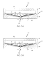
FIG. 3A is a section view taken along section line 3-3 depicted in FIG. 2 according to another embodiment of the present invention;
FIG. 3B is a section view taken along section line 3-3 depicted in FIG. 2 according to another embodiment of the present invention;
FIG. 4 is an upper side perspective view of a container according to another embodiment of the present invention shown with upper and lower housings in an open configuration thereby providing easy access to test strips provided in an upright file manner and releasably attached at an end about a rotatable central axle according to the present invention;
FIG. 5 is an upper side perspective view of the container of FIG. 5 shown with the upper and lower housings in a closed configuration thereby concealing securely the test strips therein;
FIG. 6 is a section view taken along section line 6-6 depicted in FIG. 5;
FIG. 6A is a section view taken along section line 6A-6A depicted in FIG. 5 shown with the test strips held within the retaining member via an adhesive film;
FIG. 6B is a section view taken along section line 6B-6B depicted in FIG. 5 shown with a unidirectional advancement mechanism;
FIG. 7 is a front view of a radial paddle structure over molded with TPE according to an embodiment of the present invention;
FIG. 8 is an upper side perspective view of a container according to still another embodiment of the present invention shown with upper and lower housings in an open configuration thereby providing easy access to test strips provided in an upright fan manner and releasably attached at an end about a rotatable central axle [[axel]] according to the present invention;
FIG. 9 is an upper side perspective view of the container of FIG. 7 shown with the upper and lower housings in a closed configuration thereby concealing securely the test strips therein;
FIG. 10 is a section view taken along section line 10-10 depicted in FIG. 9;
FIG. 10A is a section view taken along section line 10A-10A depicted in FIG. 10 shown with a retaining clip;
FIG. 11 is a front view of the test strips attached to an adhesive disc in a nested configuration according to an embodiment of the present invention; and
FIG. 12 is an exploded view of the container according to an embodiment of the present invention shown with upper and lower housings in an open configuration thereby providing easy access to test strips provided in an upright fan manner wherein a multiplicity of test strip carrier structures may be stacked within the cavity in the lower housing.
Skilled artisans appreciate that elements in the figures are illustrated for simplicity and clarity and have not necessarily been drawn to scale. For example, the dimensions of some of the elements in the figures may be exaggerated relative to other elements, as well as conventional parts removed, to help to improve understanding of the various embodiments of the present invention.
DETAILED DESCRIPTION
Embodiments of the present invention comprise a test strip container which provides easy access to a plurality of test strips held releasably therein. Each of the test strip container embodiments releasably retain the test strips generally enabling test strip users to easily select a single test strip from a plurality of test strips.
FIG. 1 is an upper perspective view of a test strip container according to an embodiment of the present invention. As depicted in FIG. 1, the test strip container 10 comprises an upper housing 20, a lower housing 30, and a retaining member 50. The upper and lower housings 20, 30 are shown in an open configuration thereby providing easy access to test strips 34 shown provided therein. The retaining member 50 is configured to releasably retain the test strips 34 such that the test strips 34 may be released from the container 10 when a test strip user applies pressure to the test strips 34. In FIG. 1, the test strips 34 are releasably retained by the retaining member 50 in a nested configuration such that a plurality of test strips extend radially outward from the retaining member 50. As used herein, the term “nested configuration” refers to a configuration of the test strips wherein one portion of the test strips adhered to or accommodated by the retaining member overlap such that the test strips may extend outward from the retaining member.
For example, the nested configuration as depicted in FIG. 1, comprises an arrangement of test strips 34 wherein a portion of each test strip 34 may overlap with a portion of an adjacent test strip 34. In one embodiment the overlapping portions of adjacent test strips 34 may be releasably retained by the retaining member 50 via a biasing force applied by the retaining member 50 which releasably clamps, squeezes or holds the overlapping portions together. In another embodiment the overlapping portions of the test strips 34 may be releasably attached to a surface of the retaining member 50 by an adhesive.
In the illustrated embodiments depicted by FIGS. 1 and 1A, the nested configuration allows the test strips 34 to extend radially outward from the retaining member 50 such that they are not retained in a parallel configuration. Additionally, in these embodiments the nested configuration operates to separate the radially extending portions of the test strips 34 so that they may be easily accessed by test strip users. In a further embodiment of the nested configuration, the test strips 34 are releasably retained by the retaining member 50 in a nested configuration wherein the planar side of the test strips 34 rests substantially parallel to the lower housing 30. In one embodiment, the retaining member 50 connects to the lower housing 30 within the cavity 33 such that the test strips 34 are retained within the lower housing 30.
As depicted in FIGS. 1, 1A and 1B, the lower housing 30 has surfaces 25 which define a cavity 33 for containing test strips 34. In one embodiment, the upper housing 20 has surfaces 27 which may abut with the surfaces 25 of the lower housing 30 for enclosing the cavity 33. In another embodiment, the surfaces 25, 27 may mate to provide a releasable seal to form a protective environment for the test strips 34 provided in the container 10.
The test strip container 10 comprises both an open configuration, as shown in FIGS. 1, 1A, and 1B, and a closed configuration, as shown in FIGS. 2 and 2A. The open configuration comprises the upper housing 20 being separated from the lower housing 30 wherein the uppermost test strips 34 are exposed. The exposed test strips 34 are accessible in the cavity 33 of the lower housing 30 to test strip users.
In one embodiment of the open configuration, the upper housing 20 may be hingedly attached to the lower housing 30 with a hinging mechanism 76. The hinging mechanism 76 in one embodiment may comprise a molded living hinge, such as depicted by FIGS. 1 and 1A. In this way, the upper housing 20 will not be wholly separated from the lower housing 30 in the open configuration. Rather, the upper housing 20 may pivot about the hinging mechanism 76 such that the uppermost test strips 34 are exposed within the cavity 33 of the lower housing 30. In another embodiment, the hinging mechanism 76 may comprise a pin 57 in a hole 58 arrangement, such as depicted by FIG. 12.
The closed configuration, as shown in FIGS. 2 and 2A, comprises the surfaces 25, 27 of the housings 20, 30 abutting to conceal the test strips 34 within the test strip container 10. In the closed configuration, test strips users may not access the test strips 34 within the test strip container 10. In this way, the closed configuration may be exploited to protect the test strips 34 within the test strip container 10 from moisture and other contaminants when the test strips 34 are not required for testing.
In one embodiment of the closed configuration, the test strip container 10 may optionally comprise a fastening mechanism 19 such that the test strip container 10 may be releasably fixed in the closed configuration. The fastening mechanism 19 in the embodiment illustrated by FIG. 1A is a latching mechanism comprising upper and lower releasably mating parts 29 a, 29 b, either mechanically or magnetically based, but in other embodiments, may include but is not limited thereto, a clamping mechanism or a snap-fit mechanism.
In one specific embodiment of the test strip container 10 as depicted in FIGS. 1, 1A, and 1B, the test strip container 10 may comprise a clamshell configuration. In the clamshell configuration, the upper housing 20 has surfaces including a side wall 21 and a top wall 22. The lower housing 30 also has surfaces including a side wall 35, an inner surface 31, and a bottom wall 32.
In one specific embodiment of the clamshell configuration, as depicted in FIG. 1B, the side wall 21 of the upper housing 20 and the side wall 35 of the lower housing 30 are substantially oblong and the top wall 22 of the upper housing 20 and the bottom wall 32 of the lower housing 30 are substantially flat. Thus, when in the closed configuration, as depicted in FIG. 2A, the test strip container 10 is substantially oblong with a substantially flat top wall 22 and bottom wall 32. In this particular embodiment, the retaining member 50 is substantially rectangular. The retaining member 50 retains releasably retains the test strips in a longitudinal configuration such that they extend substantially normal to the retaining member 50.
In an alternative embodiment of the clamshell configuration, as depicted in FIG. 1, the side wall 21 of the upper housing 20 and the side wall 35 of the lower housing 30 are substantially circular and the top wall 22 of the upper housing 20 and the bottom wall 32 of the lower housing 30 are substantially flat. In this particular embodiment, the retaining member 50 is substantially conical. Thus, when in the closed configuration, as depicted in FIG. 2, the test strip container 10 is substantially circular with a substantially flat top wall 22 and bottom wall 32.
In this particular embodiment of the clamshell configuration, the upper housing 20 may have a diameter slightly larger than the diameter of the lower housing 30 such that the side wall 21 of the upper housing 20 may overlap the side wall 35 of the lower housing 30 when in the closed configuration, creating an interference fit. In this way, test strip users must apply slight pressure to attain the open configuration. In an alternative embodiment, test strip users must apply a twisting force to the upper housing 20 such that it twists away from the lower housing 30 to attain the open configuration. In a further embodiment, the upper and lower housings 20, 30 may form together a moisture seal to protect the test strips from moisture and airborne debris.
As shown in FIG. 3, the clamshell configuration also comprises the lower housing 30 having a concave interior. In this particular embodiment, the inner surface 31 of the lower housing 30 extends from the center of the bottom wall 32 of the lower housing 30 to the top of the side wall 35 of the lower housing 30. In this way, the inner surface 31 of the lower housing 30 will form an acute angle with the bottom wall 32 of the lower housing 30 such that the cavity 33 defined by the inner surface 31 of the lower housing 30 is concave.
The test strips 34 contained within the lower housing 30 will rest at an angle substantially congruent to or slightly greater than the concave interior of the lower housing 30. The angular arrangement of the test strips 34 provides test strip users with easy access to the test strips 34, as the test strips 34 may be slightly elevated from the concave interior of the test strip container 10.
In a further embodiment of the clamshell configuration as depicted in FIG. 3, the retaining member 50 which releasably retains the test strips 34 is substantially conical. The conical retaining member 50 forms an angle with the bottom wall 32 of the lower housing 30 that is substantially congruent to the concave interior of the inner surface 31 of the lower housing 30. As a result, the retaining member 50 fits complementarily within the concave interior of the lower housing 30. The retaining member 50 releasably retains test strips 34 in a nested configuration wherein the application of light pressure by the test strip user to the test strips 34 causes the retaining member 50 to release the test strips 34. The retaining member 50 may be attached to the lower housing 30 or may be accommodated by the lower housing 30.
In one specific embodiment of the clamshell configuration, the retaining member 50 is a static retainer. As depicted in FIG. 3A, in this particular embodiment, the retaining member 50 is attached to a locking peg 70. In this specific embodiment, the test strips 34 are attached to an adhesive disc 71 in a nested configuration, as depicted in FIG. 11. The test strips 34 are attached to the adhesive disc 71 such that one end of the test strips 34 are adhered to the adhesive disc 71. The retaining member 50 serves to anchor the adhesive disc 71 within the lower housing 30. The locking peg 70 is arranged substantially within the center of the bottom wall 32 of the lower housing 30. In this embodiment, the retaining member 50 snaps onto the locking peg 70. In an alternative embodiment, the locking peg 70 may be integral with the bottom wall 32 of the lower housing 30 as a molded portion thereof or overmolded thereby.
In an alternative embodiment of the clamshell configuration, the lower housing 30 has a plurality of ridges 72, as depicted in FIG. 1A. The plurality of ridges 72 are arranged in a nested configuration or a longitudinal configuration such that the test strips 34 may be loaded directly into the lower housing 30 between the plurality of ridges 72. The plurality of ridges 72 are arranged such that the gap distance between each ridge is approximately equal to the width of the test strips 34. In accordance with this specific embodiment, as depicted in FIG. 3A, the retaining member 50 is a static retainer that is substantially conical. In an alternative embodiment, the retaining member 50 is substantially rectangular. In one embodiment, the retaining member 50 may be over molded. In a further embodiment, a multiplicity of test strips 34 may be loaded directly into the lower housing 30 between the plurality of ridges 72 wherein a multiplicity of test strips 34 are placed on top of one another.
In an alternative embodiment, as depicted in FIG. 3B, the retaining member 50 fits complementarily within a compliant washer 73. The compliant washer 73 comprises a compressible material. The compressible material may include but should not be limited to foam, rubber, and other elastomers. The compliant washer 73 snaps onto a locking peg 70 arranged within the lower housing 30 such that it is arranged substantially within the center of the bottom wall 32. The compliant washer 73 serves to compress the test strips 34 against the bottom wall 32 of the lower housing 30, providing sufficient friction to anchor the test strips 34 within the lower housing 30. In this specific embodiment, the lower housing 30 possesses a detent 74 which extends around the circumference of the lower housing 30. The detent 74, as depicted in FIG. 1A, allows for easy access to the test strips 34.
In an alternative embodiment of the clamshell configuration, the retaining member 50 is a dynamic retainer that is substantially conical. In another embodiment, the retaining member 50 is substantially rectangular. As depicted in FIG. 3, the retaining member 50 is spring-biased towards the inner surface 31 of the lower housing 30 in this particular embodiment. In this particular embodiment, a spring 63 has one end attached to the retaining member 50 and an opposing end attached to a compliant washer 73. The compliant washer 73 snaps onto a locking peg 70 arranged within the lower housing 30 such that it is arranged substantially within the center of the bottom wall 32.
In this particular embodiment, a multiplicity of test strips 34 may be stacked on top of one another. Removal of the test strips 34 on the top of the multiplicity of test strips 34 results in the spring 63 pulling under retraction. When the spring 63 pulls under retraction, the retaining member 50 translates downwardly toward the compliant washer 73 and the locking peg 70. The translation of the retaining member 50 results in the test strips 34 previously residing underneath the test strips 34 that were on the top layer of the stack to pivot vertically away from the concave surface of the cavity 33 due to the cone shape of the retaining member 50 moving downwardly centrally about the retained ends of the remaining test strips 34. Such a configuration thus allows test strip users to acquire a test strip easily from the multiplicity of layers of test strips contained within the test strip container 10 via the rising feature of each test strip.
In one specific embodiment of the clamshell configuration, the test strip container 10 may comprise a configuration wherein the test strips 34 are releasably stacked on top of one another. In this way, the test strips 34 releasably retained by the retaining member 50 in a nested configuration and extending radially outward from the retaining member 50 are arranged such that a multiplicity of test strips 34 are placed on top of one another.
In this way, a multiplicity of layers of test strips 34 may be contained within one test strip container 10. Where the test strips 34 are stacked, test strip users may obtain a test strip 34 from the multiplicity of test strips which are releasably retained on the top layer of the stack. In a further embodiment of the stacked configuration, the retaining member 50 may be spring-biased as previously discussed above and as shown in FIG. 3.
In an alternative embodiment of the test strip container 10, the test strip container 10 may comprise a rolodex-type configuration, as shown in FIG. 4. In the rolodex-type configuration, the lower housing 30 of the test strip container 10 has an outer surface 36 and an inner surface 37 which define a cavity 33 for containing the test strips 34. The lower housing 30 of the rolodex-type configuration comprises an aperture 41 defined by the lower housing 30 through which the plurality of test strips 34 may extend. The upper housing 20 has an outer surface 23 and an inner surface 24 such that the outer surface 23 and the inner surface 24 of the upper housing 20 abut with the outer surface 36 and the inner surface 37 of the lower housing 30 enclosing the cavity 33.
As shown in FIG. 4, the upper and lower housings 20, 30 may comprise an open configuration thereby providing easy access to the test strips 34 provided in an upright file manner and releasably attached at an end about a rotatable center axial member.
In one particular embodiment of the rolodex-type configuration, the lower housing 30 is substantially circular with an angled aperture 41 defined by the lower housing 30, and the upper housing 20 is substantially semi-circular, such that the upper housing 20 coordinates with the angled aperture 41 defined by the lower housing 30 to form a substantially circular test strip container 10 in the closed configuration shown in FIG. 5.
The retaining member 50 of the rolodex-type configuration is housed within the lower housing 30. The retaining member 50 is configured to releasably retain the test strips 34 in a nested configuration. The retaining member 50 is a radial paddle structure 55 having a plurality of paddle members 51, as depicted in FIG. 6. The retaining member 50 comprises a center axle 52 which is substantially normal to the lower housing 30 and which extends through the retaining member 50 in the lower housing 30. The retaining member 50 is connected to the lower housing 30 within the cavity 33 and is configured to releasably retain the test strips 34.
The plurality of paddle members 51 of the radial paddle structure 55 extend radially outward from the center axle 52. The radial paddle structure 55 is connected to the lower housing 30 within the cavity 33 and is configured to releasably retain the test strips 34 in a nested configuration wherein such of the test strips 34 extends radially outward from the retaining member 50. The radial paddle structure 55 snaps onto the center axle 52 in the lower housing 30. The plurality of paddle members 51 of the radial paddle structure 55 extend radially outward. The spaces in between the plurality of members 51 form a plurality of compartments 53 such that the test strips 34 may be placed within the plurality of compartments 53. The plurality of paddle members 51 of the radial paddle structure 55 extend slightly above the angled aperture 41 defined by the lower housing 30 such that the length of the plurality of paddle members 51 is less than the length of the test strips 34 along their longitudinal axis. In this way, a test strip user may grasp one of the plurality of paddle members 51 through the angled aperture 41 defined by the lower housing 30 and manually rotate the radial paddle structure 55 to the next of the plurality of compartments 53.
The nested configuration, as depicted in FIG. 6, comprises an arrangement of test strips 34 wherein a portion of each test strip 34 may overlap with a portion of another test strip 34. The overlapping portions are accommodated by the radial paddle structure 55 in the rolodex-type configuration. The nested configuration allows the test strips 34 to extend radially outward from the retaining member 50 such that they are not retained in a parallel configuration. In one specific embodiment of the rolodex-type configuration, as depicted in FIG. 6, a leaf spring 56 is added to each of the plurality of compartments 53 such that the test strips 34 may be retained within the radial paddle structure 55. In a further embodiment of the nested configuration, the test strips 34 are releasably retained by the radial paddle structure 55 in a nested configuration wherein the planar side of the test strips 34 rests substantially parallel to the plurality of members 51.
In one embodiment of the rolodex configuration, the test strips 34 are retained within the radial paddle structure 55 with a retention feature such as a foam or an adhesive film. An adhesive retainer 64 is depicted in FIG. 6A. Alternatively, the test strips 34 are accommodated by the radial paddle structure 55 by placing the test strips loosely within the plurality of compartments 53.
Rotation of the center axle 52 by the test strip user may result in rotation of the retaining member 50 such that the test strips 34 releasably retained by the radial paddle structure 55 may be rotated and accessed through the aperture 41 defined by the lower housing 30. In a further embodiment of the rolodex-type configuration, access to test strips 34 through the aperture 41 defined by the lower housing 30 may optionally be improved by angling the aperture 41 defined by the lower housing 30 such that test strips 34 may extend through a larger area. An optional feature of the rolodex-type configuration is a unidirectional advancement mechanism 60 wherein rotation of the center axle 52 is restricted to one direction.
In one specific embodiment of the rolodex-type configuration, the plurality of compartments 53 in the radial paddle structure 55 may be sealed by adding a sealing material to the inner surface 37 of the lower housing 30 which the plurality of members 51 contact. Additionally, an alternative embodiment comprises sealing the plurality of compartments 53 by over molding. Sealing the plurality of compartments 53 by over molding may comprise the use of but should not be limited to thermoplastic elastomers (i.e. TPE), rubber, or flexible polymers.
In one particular embodiment, the plurality of compartments 53 are sealed by over molding with TPE 75, as depicted in FIG. 7. The over-mold is applied on the contact edge of the radial paddle structure 55 wherein contacting the inner surface 37 of the lower housing 30 and permitting rotation of the radial paddle structure 55. The over-mold applied on the contact edge of the radial paddle structure 55 may comprise a lip seal, i.e. a wiper blade type seal. The over-mold serves as a gasket between the radial paddle structure 55 and the inner surface 37 of the lower housing 30 such that the plurality of compartments 53 are secured from any contaminants that may be encountered while the test strip container 10 is in the open configuration. More particularly, any contaminants encountered while the test strip container 10 is in the open configuration will be confined to the plurality of compartments 53 exposed in the open configuration.
Another optional feature of the rolodex-type configuration is a unidirectional advancement mechanism 60 which would operate to restrict rotation of the center axle 52 to one direction. In one specific embodiment, the unidirectional advancement mechanism is a pawl 61 and ratchet 62 as shown in FIG. 6B. In this particular embodiment, the ratchet 62 is affixed to the radial paddle structure 55 such that it rotates with the radial paddle structure 55. In this way, the pawl 61 may engage the ratchet 62, therein restricting the rotation of the radial paddle structure 55 to one direction.
In an alternative embodiment of the test strip container 10, the test strip container 10 may comprise a pinwheel configuration as depicted in FIG. 8. In the pinwheel configuration, the lower housing 30 of the test strip container 10 has an outer surface 36 and an inner surface 37 which define a cavity 33 for containing the test strips 34. The lower housing 30 of the pinwheel configuration comprises an aperture 41 defined by the lower housing 30 through which the plurality of test strips 34 may extend. The upper housing 20 has an outer surface 23 and an inner surface 24 such that the outer surface 23 and the inner surface 24 of the upper housing 20 abut with the outer surface 36 and the inner surface 37 of the lower housing 30 for enclosing the cavity 33.
As shown in FIG. 8, the upper and lower housings 20, 30 may comprise an open configuration thereby providing easy access to the test strips 34 provided in an upright fan manner and releasably attached at an end about a rotatable center axle 52.
In one particular embodiment of the pinwheel configuration, the lower housing 30 is substantially circular with an angled aperture 41 defined by the lower housing 30, as depicted in FIG. 8. The upper housing 20 is substantially semi-circular, such that the upper housing 20 coordinates with the angled aperture 41 defined by the lower housing 30 to form a substantially circular test strip container 10 in the closed configuration as shown in FIG. 9.
As shown by FIG. 10, the retaining member 50 of the pinwheel configuration is housed within the lower housing 30. The retaining member 50 is configured to releasably retain the test strips 34 in a nested configuration. The retaining member 50 is a test strip carrier structure comprising a center axle 52 and a disc 54. The center axle 52 is substantially normal to the lower housing 30 and extends through the retaining member 50 in the lower housing 30. The retaining member 50 is connected to the lower housing 30 within the cavity 33 and is configured to releasably retain the test strips 34.
The disc 54 of the pinwheel configuration is substantially planar having a diameter smaller than the length of the test strips 34, see FIG. 10. The disc 54 is arranged within the cavity 33 of the lower housing 30 such that the planar side of the disc 54 is substantially parallel to the inner surface 37 of the lower housing 30 wherein the test strips 34 may be adhered.
In an alternative embodiment of the pinwheel configuration, the test strips may be adhered to the disc 54 with a retaining clip 59 which is spring-biased, as shown in FIG. 10A. In a further embodiment, a spring 63 is connected to the retaining clip 59 such that the retaining clip 59 retains the test strips 34. In one particular embodiment, the spring 63 pulls the retaining clip 59 under retraction such that the retaining clip 59 translates toward the spring 63 in a direction parallel to the center axle 52. In an alternative embodiment, the spring 63 pushes the retaining clip 59 under expansion such that the retaining clip 59 translates toward the spring 63 in a direction parallel to the center axle 52.
In still another embodiment, the test strips may be adhered to the disc 54 with a light adhesive or with clips. In one specific embodiment, as depicted in FIG. 11, the disc 54 may be an adhesive disc 71, wherein the test strips 34 are adhered. In a further embodiment of the pinwheel configuration, the test strips 34 are adhered to the disc 54 in a nested configuration wherein the planar side of the test strips 34 rests substantially parallel to the planar side of the disc 54. In one particular embodiment of the pinwheel configuration, a multiplicity of test strip carrier structures may be stacked within the cavity 33 in the lower housing 30. In this stacked configuration, for example as depicted by FIG. 12, a plurality of discs 54 may be arranged within the lower housing 30 such that the center axle 52 extends through the plurality of discs 54. Rotation of the center axle 52 by the test strip user may result in rotation of the disc 54 such that the test strips 34 adhered to the disc 54 may also be rotated and accessed through the aperture 41 defined by the lower housing 30. In a further embodiment of the pinwheel configuration, access to test strips 34 through the aperture 41 may optionally be improved by angling the aperture 41 such that test strips 34 may extend through a larger area.
In yet another embodiment, a method of manufacturing a test strip container 10 for providing ease of access to test strips 34 is disclosed. The method comprises providing a lower housing 30 having surfaces which define a cavity 33 for containing the test strips 34, providing an upper housing 20 having surfaces which abut with the surfaces of the lower housing 30 for enclosing the cavity 33, and providing a retaining member 50 connected to the lower housing 30 within the cavity 33 and configured to releasably retain the test strips 34 in a nested configuration wherein such of the test strips 34 extends radially outward from the retaining member 50.
In still yet another embodiment, a method of providing easy access to test strips 34 which comprises utilizing a test strip container 10 according to the present invention is also disclosed.
The above description and drawings are only to be considered illustrative of exemplary embodiments, which achieve the features and advantages of the present invention. Modification and substitutions the features and steps described can be made without departing from the intent and scope of the present invention. Accordingly, the invention is not to be considered as being limited by the foregoing description and drawings, but is only limited by the scope of the appended claims.

Claims (12)

1. A test strip container for providing ease of access to test strips comprising:
a lower housing having surfaces which define a cavity for containing the test strips;
an upper housing having surfaces which abut with the surfaces of the lower housing for enclosing the cavity; and
a retaining member connected to the lower housing within the cavity and configured to releasably retain the test strips wherein each of the test strips extends outwardly from the retaining member, wherein the test strips are radially overlapping and in contact with adjacent ones thereof, and wherein the test strip container has an open configuration and a closed configuration, in which:
the open configuration comprises the upper housing being separated from the lower housing wherein the test strips are accessible in the cavity of the lower housing, and
the closed configuration comprises the surfaces of the upper housing and the lower housing abutting to conceal the test strips within the test strip container.
2. The test strip container of claim 1, wherein the upper housing and the lower housing are substantially circular.
3. The test strip container of claim 2, wherein the test strips are retained in a nested configuration wherein each of the test strips extends radially outward from the retaining member.
4. The test strip container of claim 3, wherein the cavity of the lower housing is a concave interior.
5. The test strip container of claim 4, wherein the test strips rest at an angle substantially congruent to the concave interior of the lower housing.
6. The test strip container of claim 5, wherein the retaining member is substantially conical having an angle substantially congruent to the concave interior of the lower housing.
7. The test strip container of claim 6, wherein the test strips are arranged such that a multiplicity of test strips are placed on top of one another.
8. The test strip container of claim 1, wherein the upper housing and the lower housing are substantially oblong.
9. The test strip container of claim 8, wherein the retaining member is substantially rectangular.
10. The test strip container of claim 9, wherein the test strips are retained in a longitudinal configuration such that they extend substantially normal to the retaining member.
11. A method of manufacturing a test strip container for providing easy access to test strips, comprising:
providing a lower housing having surfaces which define a cavity for containing the test strips;
providing an upper housing having surfaces which abut with the surfaces of the lower housing for enclosing the cavity; and
providing a retaining member connected to the lower housing within the cavity and configured to releasably retain the test strips in a nested configuration wherein such of the test strips extends radially outward from the retaining member and wherein the test strips are radially overlapping and in contact with adjacent ones thereof.
12. A method of providing easy access to test strips which comprises utilizing the test strip container of claim 1.
US12/646,167 2009-12-23 2009-12-23 Easy strip access primary container and methods of manufacturing and utilization thereof Expired - Fee Related US8066957B2 (en)

Priority Applications (3)

Application Number Priority Date Filing Date Title
US12/646,167 US8066957B2 (en) 2009-12-23 2009-12-23 Easy strip access primary container and methods of manufacturing and utilization thereof
PCT/EP2010/007695 WO2011076362A1 (en) 2009-12-23 2010-12-15 Test strip container
US13/278,896 US8158078B2 (en) 2009-12-23 2011-10-21 Easy strip access primary container and methods of manufacturing and utilization thereof

Applications Claiming Priority (1)

Application Number Priority Date Filing Date Title
US12/646,167 US8066957B2 (en) 2009-12-23 2009-12-23 Easy strip access primary container and methods of manufacturing and utilization thereof

Related Child Applications (1)

Application Number Title Priority Date Filing Date
US13/278,896 Division US8158078B2 (en) 2009-12-23 2011-10-21 Easy strip access primary container and methods of manufacturing and utilization thereof

Publications (2)

Publication Number Publication Date
US20110147244A1 US20110147244A1 (en) 2011-06-23
US8066957B2 true US8066957B2 (en) 2011-11-29

Family

ID=43567675

Family Applications (2)

Application Number Title Priority Date Filing Date
US12/646,167 Expired - Fee Related US8066957B2 (en) 2009-12-23 2009-12-23 Easy strip access primary container and methods of manufacturing and utilization thereof
US13/278,896 Active US8158078B2 (en) 2009-12-23 2011-10-21 Easy strip access primary container and methods of manufacturing and utilization thereof

Family Applications After (1)

Application Number Title Priority Date Filing Date
US13/278,896 Active US8158078B2 (en) 2009-12-23 2011-10-21 Easy strip access primary container and methods of manufacturing and utilization thereof

Country Status (2)

Country Link
US (2) US8066957B2 (en)
WO (1) WO2011076362A1 (en)

Cited By (3)

* Cited by examiner, † Cited by third party
Publication number Priority date Publication date Assignee Title
US20110253736A1 (en) * 2010-04-16 2011-10-20 Frank David Fujimoto Analyte test strip vial
US20120080330A1 (en) * 2010-09-30 2012-04-05 Rush Benjamin M Analyte Test Strip Containers and Inserts
USD844969S1 (en) * 2018-01-05 2019-04-09 Chengsong Xiao Earbuds case

Families Citing this family (11)

* Cited by examiner, † Cited by third party
Publication number Priority date Publication date Assignee Title
JP2009225936A (en) * 2008-03-21 2009-10-08 Nitto Denko Corp Bodily fluid collecting circuit board, method of manufacturing the same, method of using the same, and biosensor
TWI522087B (en) * 2010-07-08 2016-02-21 賽諾菲阿凡提斯德意志有限公司 Blood sample collection
KR101340006B1 (en) * 2011-12-01 2013-12-10 주식회사 세라젬메디시스 Cartridge of analysis apparatus
US9417229B2 (en) 2011-12-20 2016-08-16 Ascensia Diabetes Care Holdings Ag Linear, cartridge-based glucose measurement system
US9097700B2 (en) * 2011-12-29 2015-08-04 Bayer Healthcare Llc Glucose measurement system with high-capacity cartridge and capability of more frequent replenishment
CA2873410C (en) 2012-05-31 2017-10-03 Bayer Healthcare Llc Multistrip cartridge
US9383333B2 (en) 2012-05-31 2016-07-05 Ascensia Diabetes Care Holdings Ag Replaceable multistrip cartridge and biosensor meter
WO2014118359A1 (en) * 2013-02-04 2014-08-07 Clariant Production (France) Sas Dispensing device for holding and dispensing strip-like objects
CN105209908B (en) 2013-03-12 2018-01-09 安晟信医疗科技控股公司 With the test-strips gauge for push to test bar against the mechanism of optical reader
US9517467B1 (en) * 2015-12-08 2016-12-13 Paratus Diagnostics, LLC Point-of-care diagnostic cartridge
EP3517957B1 (en) * 2018-01-24 2019-12-18 Midge Medical GmbH Testing assembly and testing device for lateral flow assay

Citations (11)

* Cited by examiner, † Cited by third party
Publication number Priority date Publication date Assignee Title
US3651927A (en) * 1969-10-21 1972-03-28 Cambridge Res & Dev Group Tablet dispenser
US4231624A (en) 1978-11-09 1980-11-04 The Rolodex Corporation Locking rotary file
US4906057A (en) 1983-11-10 1990-03-06 Rolodex Corporation Closed portable card file
US5378630A (en) 1991-11-14 1995-01-03 Hitachi, Ltd. Test strip automatic supply device and analytical instrument using the same
US5505308A (en) 1993-08-27 1996-04-09 Boehringer Mannheim Gmbh System for the storage of test elements
US5720924A (en) * 1993-04-23 1998-02-24 Boehringer Mannheim Gmbh Storage system for test elements
US20030185708A1 (en) 2002-04-02 2003-10-02 Gary Otake Test strip containers and methods of using the same
US20060064035A1 (en) 2004-09-17 2006-03-23 Yi Wang Multiple-biosensor article
EP1855110A2 (en) 2006-05-09 2007-11-14 Becton, Dickinson & Company Method and Apparatus for Dispensing Diagnostic Test Strips
EP2031389A1 (en) 2007-09-03 2009-03-04 Airsec S.A.S. Vial
US7723113B2 (en) * 2001-08-20 2010-05-25 Bayer Healthcare Llc Packaging system for test sensors

Family Cites Families (1)

* Cited by examiner, † Cited by third party
Publication number Priority date Publication date Assignee Title
US20070196240A1 (en) 2006-02-23 2007-08-23 Agamatrix, Inc. Multi-slot Test strip vial

Patent Citations (14)

* Cited by examiner, † Cited by third party
Publication number Priority date Publication date Assignee Title
US3651927A (en) * 1969-10-21 1972-03-28 Cambridge Res & Dev Group Tablet dispenser
US4231624A (en) 1978-11-09 1980-11-04 The Rolodex Corporation Locking rotary file
US4906057A (en) 1983-11-10 1990-03-06 Rolodex Corporation Closed portable card file
US5378630A (en) 1991-11-14 1995-01-03 Hitachi, Ltd. Test strip automatic supply device and analytical instrument using the same
US5863800A (en) 1993-04-23 1999-01-26 Boehringer Mannheim Gmbh Storage system for test elements
US5720924A (en) * 1993-04-23 1998-02-24 Boehringer Mannheim Gmbh Storage system for test elements
US5505308A (en) 1993-08-27 1996-04-09 Boehringer Mannheim Gmbh System for the storage of test elements
US7723113B2 (en) * 2001-08-20 2010-05-25 Bayer Healthcare Llc Packaging system for test sensors
US20030185708A1 (en) 2002-04-02 2003-10-02 Gary Otake Test strip containers and methods of using the same
US7172728B2 (en) 2002-04-02 2007-02-06 Lifescan, Inc. Test strip containers and methods of using the same
US20060064035A1 (en) 2004-09-17 2006-03-23 Yi Wang Multiple-biosensor article
EP1855110A2 (en) 2006-05-09 2007-11-14 Becton, Dickinson & Company Method and Apparatus for Dispensing Diagnostic Test Strips
US20070264166A1 (en) 2006-05-09 2007-11-15 Becton, Dickinson And Company Method and apparatus for dispensing diagnostic test strips
EP2031389A1 (en) 2007-09-03 2009-03-04 Airsec S.A.S. Vial

Cited By (5)

* Cited by examiner, † Cited by third party
Publication number Priority date Publication date Assignee Title
US20110253736A1 (en) * 2010-04-16 2011-10-20 Frank David Fujimoto Analyte test strip vial
US8919607B2 (en) * 2010-04-16 2014-12-30 Abbott Diabetes Care Inc. Analyte test strip vial
US20120080330A1 (en) * 2010-09-30 2012-04-05 Rush Benjamin M Analyte Test Strip Containers and Inserts
US8757386B2 (en) * 2010-09-30 2014-06-24 Abbott Diabetes Care Inc. Analyte test strip containers and inserts
USD844969S1 (en) * 2018-01-05 2019-04-09 Chengsong Xiao Earbuds case

Also Published As

Publication number Publication date
US20120037521A1 (en) 2012-02-16
US20110147244A1 (en) 2011-06-23
US8158078B2 (en) 2012-04-17
WO2011076362A1 (en) 2011-06-30

Similar Documents

Publication Publication Date Title
US8066957B2 (en) Easy strip access primary container and methods of manufacturing and utilization thereof
US20070196240A1 (en) Multi-slot Test strip vial
US8622231B2 (en) Storage containers for test elements
JP4927133B2 (en) Containers for reading and handling diagnostic reagents and methods for using the containers
JP4355052B2 (en) Storage container for analytical devices
AU2011293832B2 (en) Biological fluid sampling and storage apparatus for remote use
WO2007043012A2 (en) Vial for test strips
US7516845B2 (en) Medical device package with deformable projections
US9341613B2 (en) Device for singulating and dispensing rigid and semi-rigid strips
CN1432813A (en) Test chip and strip distributor
US8394343B2 (en) Integrated test strip container with retaining insert
US8757386B2 (en) Analyte test strip containers and inserts
US20100329951A1 (en) Test Sensor Package
US20160001927A1 (en) Containers with inserts
FR2810405A1 (en) Color comparator quantitatively indicating specific substances in body fluids, combines plastic test strip, resembling clock hand, with circular, plastic-covered card printed with indicative colors and corresponding concentrations
WO2011089144A1 (en) Test strip container with strip retainer and methods of manufacturing and utilization thereof
US20110182785A1 (en) Flat Pop-Up Primary Container And Methods of Manufacturing And Utilization Thereof
CN101124482B (en) Test sensor cartridges and sensor-dispensing instruments
EP0349771A1 (en) Passive radiation detector
JP2010509589A (en) Test sensor cartridge
EP4077161B1 (en) Device for storing and dispensing strips
FR3100889A1 (en) Biological fluid sample collection device
JP2021116107A (en) Moisture-proof container
EP0269304A1 (en) Disposable test device
JP2004277040A (en) Adhesive tape storage cutter

Legal Events

Date Code Title Description
AS Assignment

Owner name: ROCHE DIAGNOSTICS OPERATIONS, INC., INDIANA

Free format text: ASSIGNMENT OF ASSIGNORS INTEREST;ASSIGNORS:CHAN, FRANK A.;WIEGEL, CHRIS;SIGNING DATES FROM 20100119 TO 20100120;REEL/FRAME:023908/0840

ZAAA Notice of allowance and fees due

Free format text: ORIGINAL CODE: NOA

ZAAB Notice of allowance mailed

Free format text: ORIGINAL CODE: MN/=.

STCF Information on status: patent grant

Free format text: PATENTED CASE

CC Certificate of correction
FPAY Fee payment

Year of fee payment: 4

AS Assignment

Owner name: ROCHE DIABETES CARE, INC., INDIANA

Free format text: ASSIGNMENT OF ASSIGNORS INTEREST;ASSIGNOR:ROCHE DIAGNOSTICS OPERATIONS, INC.;REEL/FRAME:036008/0670

Effective date: 20150302

MAFP Maintenance fee payment

Free format text: PAYMENT OF MAINTENANCE FEE, 8TH YEAR, LARGE ENTITY (ORIGINAL EVENT CODE: M1552); ENTITY STATUS OF PATENT OWNER: LARGE ENTITY

Year of fee payment: 8

FEPP Fee payment procedure

Free format text: MAINTENANCE FEE REMINDER MAILED (ORIGINAL EVENT CODE: REM.); ENTITY STATUS OF PATENT OWNER: LARGE ENTITY

LAPS Lapse for failure to pay maintenance fees

Free format text: PATENT EXPIRED FOR FAILURE TO PAY MAINTENANCE FEES (ORIGINAL EVENT CODE: EXP.); ENTITY STATUS OF PATENT OWNER: LARGE ENTITY

STCH Information on status: patent discontinuation

Free format text: PATENT EXPIRED DUE TO NONPAYMENT OF MAINTENANCE FEES UNDER 37 CFR 1.362

FP Lapsed due to failure to pay maintenance fee

Effective date: 20231129