US8063381B2 - Achromatic and uncoupled medical gantry - Google Patents
Achromatic and uncoupled medical gantry Download PDFInfo
- Publication number
- US8063381B2 US8063381B2 US12/403,486 US40348609A US8063381B2 US 8063381 B2 US8063381 B2 US 8063381B2 US 40348609 A US40348609 A US 40348609A US 8063381 B2 US8063381 B2 US 8063381B2
- Authority
- US
- United States
- Prior art keywords
- gantry
- dipole
- quadrupoles
- particle beam
- quadrupole
- Prior art date
- Legal status (The legal status is an assumption and is not a legal conclusion. Google has not performed a legal analysis and makes no representation as to the accuracy of the status listed.)
- Active, expires
Links
Images


Classifications
-
- H—ELECTRICITY
- H05—ELECTRIC TECHNIQUES NOT OTHERWISE PROVIDED FOR
- H05H—PLASMA TECHNIQUE; PRODUCTION OF ACCELERATED ELECTRICALLY-CHARGED PARTICLES OR OF NEUTRONS; PRODUCTION OR ACCELERATION OF NEUTRAL MOLECULAR OR ATOMIC BEAMS
- H05H7/00—Details of devices of the types covered by groups H05H9/00, H05H11/00, H05H13/00
- H05H7/04—Magnet systems, e.g. undulators, wigglers; Energisation thereof
-
- A—HUMAN NECESSITIES
- A61—MEDICAL OR VETERINARY SCIENCE; HYGIENE
- A61N—ELECTROTHERAPY; MAGNETOTHERAPY; RADIATION THERAPY; ULTRASOUND THERAPY
- A61N5/00—Radiation therapy
- A61N5/10—X-ray therapy; Gamma-ray therapy; Particle-irradiation therapy
-
- A—HUMAN NECESSITIES
- A61—MEDICAL OR VETERINARY SCIENCE; HYGIENE
- A61N—ELECTROTHERAPY; MAGNETOTHERAPY; RADIATION THERAPY; ULTRASOUND THERAPY
- A61N5/00—Radiation therapy
- A61N5/10—X-ray therapy; Gamma-ray therapy; Particle-irradiation therapy
- A61N5/1077—Beam delivery systems
- A61N5/1081—Rotating beam systems with a specific mechanical construction, e.g. gantries
-
- A—HUMAN NECESSITIES
- A61—MEDICAL OR VETERINARY SCIENCE; HYGIENE
- A61N—ELECTROTHERAPY; MAGNETOTHERAPY; RADIATION THERAPY; ULTRASOUND THERAPY
- A61N5/00—Radiation therapy
- A61N5/10—X-ray therapy; Gamma-ray therapy; Particle-irradiation therapy
- A61N2005/1085—X-ray therapy; Gamma-ray therapy; Particle-irradiation therapy characterised by the type of particles applied to the patient
- A61N2005/1087—Ions; Protons
Definitions
- This invention relates generally to a cancer therapy and, more particularly, to a medical particle delivery system having an achromatic and uncoupled gantry design.
- X-ray beams are typically used to treat cancer.
- X-rays release much of their energy quickly after penetrating the skin, disrupting the molecules of healthy tissue and organs.
- Protons, neutron, ⁇ -ray or other ion rays have excellent physical properties for radiation therapy which permit one to control very precisely the shape of the dose distribution inside the patient's body.
- the dose delivered by such an ion ray beam is well localized in space, not only in the lateral direction, but also very precisely in depth, due to the presence of the characteristic Bragg peak.
- ion ray therapy is effective because of its ability to accurately target and kill tumors, both near the surface and deep seated within the body, while minimizing damage to the surrounding tissues. For this reason, it is favored for treating certain kinds of tumors where conventional X-ray and radiation oncology would damage surrounding tissues to an unacceptable level.
- a particle accelerator such as a synchrotron
- a gantry arrangement to deliver a beam of ion particles from a single source to one of a plurality of patient treatment stations for cancer therapy.
- Such cancer treatment facilities are widely known throughout the world.
- U.S. Pat. No. 4,870,287 to Cole et al. discloses a multi-station proton beam therapy system for selectively generating and transporting proton beams from a single proton source and accelerator to one of a plurality of patient treatment stations each having a rotatable gantry for delivering the proton beams at different angles to the patients.
- the beam delivery portion of the Cole et al. system includes a switchyard and gantry arrangement.
- the switchyard utilizes switching magnets that selectively direct the proton beam to the desired patient treatment station.
- Each patient treatment station includes a gantry having an arrangement of three bending dipole magnets and two focusing quadrupole magnets between each set of bending dipole magnets.
- the gantry is fully rotatable about a given axis so that the proton beam may be delivered at any desired angle to the patient located at the isocenter of the gantry.
- the gantry of typical particle beam cancer therapy systems accepts a particle beam of a required energy from the accelerator and projects it with a high precision toward a cancerous tumor within a patient.
- the beam from the gantry must be angularly adjustable so that the beam can be directed into the patient from above and all sides.
- Benedikt, et al. proposed to use a special matching section, called a “rotator,” which in essence a plurality of quadrupole magnets positioned just in front of the gantry present in addition to the quadrupole magnets within the gantry.
- the rotator allows for the section of the beam line just before the gantry to be synchronously rotated in proportion to the gantry rotation.
- the disadvantage of the Benedikt et al. system is that it occupies about 10 m of extra length of the transfer line and requires an extra equipment for extremely precise mechanical rotation, which is a significant drawback for design of compact medical accelerator complexes appropriate for use in the hospital facilities.
- Dolinskii Yet another approach to overcome beam dependence on the angle of gantry rotation was proposed by Dolinskii and disclosed in the U.S. Pat. No. 6,476,403.
- the gantry design of Dolinskii is based on a plurality of quadrupoles that create a fully achromatic beam transport, which is independent of gantry rotation. Nonetheless, the drawback of such a system is that the beam at the entrance of the gantry must be constrained to have the same angular divergence or size in the horizontal and vertical planes, which requires additional system to control the beam itself.
- the present invention provides for a particle therapy gantry for delivering a particle beam to a patient independent of the gantry rotation by maintaining the particle beam achromatic and linearly uncoupled.
- the medical gantry includes a plurality of dipole magnets that bend the trajectory of the beam path onto a patient, and a plurality of quadrupole magnets that focus the beam and maintain a small, high-precision beam spot at the patient by creating an achromatic and linearly uncoupled conditions at the exit of the gantry independent of its rotation.
- the beam tube of the gantry preferably includes a particle beam entry point, a transition path, a particle beam exit point, a first dipole sector bend of the particle beam path, a second dipole sector bend of the particle beam path, and a third dipole sector bend of the particle beam path.
- the first and the second dipole sector bends of the particle beam path provide a parallel translation of the beam in the plane if the bend are equal but opposite.
- the first and the second dipole sector bend of the particle beam path do not provide a parallel translation of the beam in the plane as exemplified below.
- the third sector bend of the particle beam path directs the particle beam to the isocenter of the gantry, in the direction of a patient.
- the particle beam passing through each sectors may be bend by any desired angle as long as the combinations of three bends redirects the particle beam to the isocenter of the beam path. In one embodiment, the combination of three angles, by which the beam path is bend, is about ninety degrees.
- the beam tube of the gantry preferably includes a plurality of quadrupole magnets to control the beam size and shape at the exit of the gantry to afford the rotation of the gantry independent of the beam.
- the gantry includes six quadrupole magnets positioned between the first and the second dipole sector bends and six quadrupole magnets positioned between the second and the third dipole sector bends arranged in symmetrical pairs about the center between the sector bends to produce achromatic and uncoupled beam transfer.
- the gantry includes in additional to the symmetrically positioned six quadrupole magnets between dipole sector bends, a quadrupole magnet positioned at the line center between the first and the second dipole sector bends and/or between the second and the third dipole sector bends to produce achromatic and uncoupled beam transfer with additional control on the ⁇ functions to reduce the aperture of the second and/or third dipole.
- the gantry includes eight quadrupole magnets, where four are positioned along the axis of rotation before the first dipole sector bend, two are positioned between the first and the second dipole sector bends and two are positioned between the second and the third dipole sector bends arranged to produce achromatic and uncoupled beam transfer.
- the size and shape of the particle beam at the exit of the gantry is independent of the angle of gantry rotation, and wherein the gantry can be rotated by any angle between 0 and 360 with respect to a fixed incoming beam line.
- the strength and the location of the plurality of quadrupoles are maintained to achieve the ⁇ functions of less than about 30 m between a set of dipoles and the ⁇ functions of less than about 5.5 m at the exit of the third dipole.
- the drift between the first and the second dipole magnet is about 5 m.
- the present invention further involves a method for delivering a particle beam to a patient through a gantry.
- the method generally includes the steps of bending the particle beam with a plurality of fixed field dipole magnets sequentially arranged along a beam path of the gantry, and the steps of maintaining achromatic and uncoupled conditions of the beam at the exit of the gantry with a plurality of quadrupole magnets which are arranged symmetrically in pair between the fixed field dipole magnets.
- the method additionally includes the steps of providing ⁇ function control by incorporating an additional quadrupole magnet at the center between the two dipole sector bends.
- the gantry of the present invention may be utilized in a medical particle beam therapy system having a source of particles, a particle accelerator, an injector for transporting particles from the source to the accelerator, one or more patient treatment stations including rotatable gantries of the present invention for delivering a particle beam to a patient and a beam transport system for transporting the accelerated beam from the accelerator to the patient treatment station.
- FIG. 1 is a top plan view of a typical medical particle delivery therapy facility.
- FIG. 2 is a schematic view of a rotating gantry.
- FIG. 3 is a cross-sectional view of the gantry with six (6) quadrupole magnets between each dipole pair to control beam achromaticity and coupling according to the present invention.
- FIG. 4 is a cross-sectional view of the gantry with seven (7) quadrupole magnets between the first and second dipole magnets and six (6) quadrupole magnets between second and third dipole magnets to control beam achromaticity and coupling according to the present invention.
- FIG. 5 is a cross-sectional view of the gantry with six (6) quadrupole magnets between the first and second dipole magnets and seven (7) quadrupole magnets between second and third dipole magnets to control beam achromaticity and coupling according to the present invention.
- FIG. 6 is a cross-sectional view of the gantry with seven (7) quadrupole magnets between each dipole pair to control beam achromaticity and coupling according to the present invention.
- the quadrupole magnets are arranged in groups of seven (7) between each set of dipoles.
- FIG. 7 is a cross-sectional view of an alternative design of a gantry that provides achromatic and uncoupled beam.
- the gantry is sequentially comprised of four (4) quadrupoles, placed along the rotation axis of the gantry, a dipole, two (2) quadrupoles, a dipole, two (2) quadrupoles and a dipole.
- FIG. 8 shows the beta and dispersion ( ⁇ x , ⁇ y and ⁇ x , ⁇ y ) functions plotted along the line as calculated using the computer code MAD in the “coupled” mode with six quadrupoles between a dipole pair as shown in FIGS. 3 , 4 and 5 .
- FIG. 9 shows the beta and dispersion ( ⁇ x , ⁇ y , and ⁇ x , ⁇ y ) functions plotted along the line as calculated using the computer code MAD in the “coupled” mode for a gantry setup with seven quadrupoles between a dipole pair as shown in FIGS. 4 , 5 , and 6 .
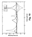
- FIG. 10 shows the beta and dispersion ( ⁇ x , ⁇ y , and ⁇ x , ⁇ y ) functions plotted along the full gantry line as calculated using the computer code MAD in the “coupled” mode for a gantry setup with seven quadrupoles between each dipole pair as shown in FIG. 6 .
- the values of the dispersion functions shown in the Figure are multiplied by a factor of 10.
- FIG. 11 shows the beta and dispersion ( ⁇ x , ⁇ y , and ⁇ x , ⁇ y ) functions plotted along the line as calculated using the computer code MAD in the “coupled” mode for a gantry setup with seven quadrupoles shown in FIG. 7 .
- FIG. 1 shows a typical medical particle delivery therapy facility 1 .
- the facility 1 generally includes an injector 2 , a particle accelerator 3 , and a beam delivery network 4 including a rotatable gantry treatment room 10 for delivering a beam to a patient.
- the beam delivery network 4 may also be designed to divert independent beams to various other applications as desired.
- the beam delivery network 4 may be designed to deliver a beam to a beam research room 5 and a fixed beam treatment room 6 .
- the research room 5 may be provided for research and calibration purposes, with an entrance separate from the patient areas, while the fixed beam treatment room 6 may include separate beam lines for such therapeutic applications, such as eye treatments.
- the beam injector module 2 can be a conventional LINAC or a tandem Van de Graaf injector with an injection kicker, which completes the task of particle injection into the accelerator 3 .
- the injector typically provides proton beam pulses at 30 Hz with a pulse width varying between 25 and 100 nanoseconds at a delivered energy of 7 MeV.
- the particle accelerator 3 can be a synchrotron, cyclotron or some other conventional design known in the prior art.
- the accelerator 3 accelerates particles to a desired energy level for extraction and delivery to the patient treatment rooms 6 and 10 . Variation of the extraction energy is achieved by adjusting, for example, an RF frequency within the accelerator 3 . Again for proton particles, extraction typically occurs when the kinetic energy of the particles is in the range 60 to 250 MeV. For examples, see U.S. Pat. No. 4,870,287 to Cole et al. incorporated herein in its entirety by reference.
- the beam delivery network 4 connects the accelerator 3 to the treatment rooms 6 and 10 and the beam research room 5 .
- the network 4 generally includes an extraction line 7 , a switchyard 8 and a plurality of beam transport lines 9 .
- the switchyard 8 is typically an arrangement of switching magnets for diverting the particle beam to a desired beam line 9 .
- the beam transport lines 9 take the particle beam from the switchyard 8 to the different treatment rooms of the facility 6 and 10 .
- FIG. 2 shows schematic representation of the rotatable gantry treatment room 10 includes a rotating gantry 11 , which is rotatable by plus or minus 200 degrees from the vertical about an axis of rotation 16 to deliver a particle beam to a patient at a gantry isocenter 15 .
- the gantry system accepts particles already accelerated to required energy delivered by the beam delivery network 4 from the particle accelerator 3 .
- the first part 12 of the gantry bends particles by a certain angle normally less than 90°.
- the second part 13 of the gantry bends the particles by same or similar angle of the first part 12 but in the opposite direction.
- the third part 14 of the gantry bends the particle by approximately 90° but may be different as long as the bending of the beam by three dipole magnets 12 , 13 and 14 brings the particles towards the required direction of the isocenter 15 .
- the gantry 11 is constructed as a three-dimensional structure supported by multiple bearings on the treatment room side and, on the beam inlet side.
- the gantry is further preferably balanced around its rotation axis.
- Gantry movement can be realized by a gear motor/gear ring drive that allows high precision positioning.
- Each gantry is preferably controlled by means of an individual independent computer unit that ensures mutual braking of the main drive units, soft start and soft deceleration functions, control of the auxiliary drive units for the treatment room, and supervision of the limit switches.
- the gantry further includes a nozzle for delivering the particle beam to the patient and may further include a plurality of scanning magnets.
- U.S. Pat. No. 4,870,287 to Cole et al. and U.S. Pat. App. No. 2007/0262269 to Trbojevic et al. all incorporated herein in their entirety by reference.
- the beam generated by the particle accelerator normally is non-symmetric and have different emittances in horizontal and vertical planes.
- the non-symmetry of the beam complicates the matching of the transfer line to the rotating gantry.
- the input beam parameters in the horizontal and vertical planes of the gantry become a function of the angle of gantry rotation and are transformed to the beam parameters at the gantry exit.
- the matching of the transfer line to the rotating gantry for the non-symmetrical beam independent of the gantry angle of rotation can be made. This is explained below, by using a beam line which displaces the beam in both the horizontal and vertical planes simultaneously, with the beam line preserving achromatic and linearly uncoupled conditions of beam transfer.
- the beam can be mathematically described by a 6 ⁇ 6 ⁇ -matrix that have form:
- ⁇ - matrix ⁇ 11 ⁇ 12 ⁇ 13 ⁇ 14 ⁇ 15 ⁇ 16 ⁇ 21 ⁇ 22 ⁇ 23 ⁇ 24 ⁇ 25 ⁇ 26 ⁇ 31 ⁇ 32 ⁇ 33 ⁇ 34 ⁇ 35 ⁇ 36 ⁇ 41 ⁇ 42 ⁇ 43 ⁇ 44 ⁇ 45 ⁇ 46 ⁇ 51 ⁇ 52 ⁇ 53 ⁇ 54 ⁇ 55 ⁇ 56 ⁇ 61 ⁇ 62 ⁇ 63 ⁇ 64 ⁇ 65 ⁇ 66 ⁇ ( 1 ) where the matrix describes a beam which is distributed in Gaussian space in any of the six coordinates (x, x′, y, y′, ⁇ 1, ⁇ p/p 0 ).
- the size or the angular divergence of the beam is given by the square root of the diagonal terms of the ⁇ -matrix. If the beam is uncoupled and achromatic, the elements of the ⁇ -matrix coupling in the horizontal and vertical phase vanish and the ⁇ -matrix can be expressed as:
- ⁇ - matrix ⁇ 11 ⁇ 12 0 0 0 0 0 ⁇ 21 ⁇ 22 0 0 0 0 0 0 ⁇ 33 ⁇ 34 0 0 0 0 0 ⁇ 43 ⁇ 44 0 0 0 0 0 0 0 0 ⁇ 55 0 0 0 0 0 0 ⁇ 66 ( 2 )
- ⁇ exit ( ⁇ ) R ( ⁇ ) ⁇ ent ⁇ R ( ⁇ ) T (3)
- R( ⁇ ) T is a transpose matrix of R( ⁇ ), which represents a beam transport system (an arrangement of quadrupole and dipole magnets) that allow to transport the beam ( ⁇ -matrix) from the entrance ( ⁇ entr ) to the exit ( ⁇ exit ) of the gantry at a defined rotation of the gantry ⁇ .
- the rotation matrix R rot ( ⁇ ) describes the rotation of the coordinate system by an angle ⁇ represented by
- R rot ⁇ ( ⁇ ) cos ⁇ ( ⁇ ) 0 sin ⁇ ( ⁇ ) 0 0 cos ⁇ ( ⁇ ) 0 sin ⁇ ( ⁇ ) - sin ⁇ ( ⁇ ) 0 cos ⁇ ( ⁇ ) 0 0 - sin ⁇ ( ⁇ ) 0 cos ⁇ ( ⁇ ) ( 5 ) and the transfer matrix R trans describes quadrupole arrangements within gantry represented by
- R trans R 11 R 12 R 13 R 14 R 15 R 16 R 21 R 22 R 23 R 24 R 25 R 26 R 31 R 32 R 33 R 34 R 35 R 36 R 41 R 42 R 43 R 44 R 45 R 46 R 51 R 52 R 53 R 54 R 55 R 56 R 61 R 62 R 63 R 64 R 65 R 66 ( 6 )
- R trans R 11 R 12 0 0 0 0 R 21 R 22 0 0 0 0 0 R 33 R 34 0 0 0 0 R 43 R 44 0 0 0 0 0 0 0 1 0 0 0 0 0 0 0 1 ( 7 )
- the beam becomes dependent on the angle of gantry rotation.
- the non-zero matrix elements R ij of the R trans matrix must be constant and have a form:
- Dispersion in the particle beam refers to a phenomenon of particle deviation from the original trajectory due the fact that the particle beam comprises an ensemble of many particles with different momenta. Dispersion is created by beam transport elements such as dipole magnets that bend the reference trajectory of the beam, whereas typical dispersion-free elements are drift space and quadrupole magnets. Without special precautions, a beam-transport system containing bending dipole magnets is, in general, chromatic.
- the transport matrix of the first sector dipole (1) may be written in the form of 2 ⁇ 2 blocks as
- angles ⁇ and ⁇ represent the bend angles produced by the first and second dipole magnets (see FIG. 3 ).
- B 2 ( M x 0 - D 0 M y 0 D ⁇ 0 G ) ( 10 ) with only the upper right and lower left 2 ⁇ 2 blocks of opposite sign from B 1 . Both bends have the same diagonal blocks.
- M x N x D In order to cancel the dispersion, M x N x D must equal D, i.e., the second column of D must be an eigenvector of M x N x with eigenvalue of 1. Rearranging the achromatic condition gives the pair of equations:
- N x ( a - ( 1 + a ) ⁇ ⁇ ⁇ ⁇ tan ⁇ ⁇ 2 1 - a ⁇ ⁇ cot ⁇ ⁇ 2 a ) ( 14 ) which has identical values on the diagonal. Given values of ⁇ and ⁇ for the bends are constant, then there is only one degree of freedom left in N x for R( ⁇ ) to be achromatic, with only 2 ⁇ 2 blocks along the diagonal of R( ⁇ ) and blocks of zeros away from the diagonal. Uncoupled Conditions
- FIGS. 3 , 4 , 5 , 6 , and 7 An illustrative gantry setup of the present invention is shown in FIGS. 3 , 4 , 5 , 6 , and 7 .
- the gantry consists of two opposite sector dipoles 2 and 3 bending the beam 1 by angles ⁇ and ⁇ in opposite directions that provide a parallel translation of the beam in a plane 6 .
- the gantry further includes dipole 4 and 5 that provides a redirection of the beam onto the patient/isocenter 5 .
- the gantry consists of a plurality of quadrupoles.
- FIG. 3 shows a gantry setup with six quadrupoles 24 - 29 placed symmetrically between dipoles 2 and 3 and six quadrupoles 30 - 35 placed symmetrically between dipoles 4 and 5 .
- FIG. 3 shows a gantry setup with six quadrupoles 24 - 29 placed symmetrically between dipoles 2 and 3 and six quadrupoles
- FIG. 4 shows a gantry setup with seven quadrupoles 29 - 30 placed symmetrically between dipoles 2 and 3 with quadrupole 30 at the center and six quadrupoles 31 - 36 placed symmetrically between dipoles 4 and 5 .
- FIG. 5 shows a gantry setup with six quadrupoles 24 - 29 placed symmetrically between dipoles 2 and 3 and seven quadrupoles 30 - 36 placed symmetrically between dipoles 4 and 5 with quadrupole 33 at the center.
- FIG. 5 shows a gantry setup with six quadrupoles 24 - 29 placed symmetrically between dipoles 2 and 3 and seven quadrupoles 30 - 36 placed symmetrically between dipoles 4 and 5 with quadrupole 33 at the center.
- FIG. 6 shows a gantry setup with seven quadrupoles 24 - 30 placed symmetrically between dipoles 2 and 3 with quadrupole 30 at the center and seven quadrupoles 31 - 37 placed symmetrically between dipoles 4 and 5 with quadrupole 34 at the center.
- FIG. 6 shows a gantry setup with four quadrupoles 20 - 23 placed along the rotation axis of the gantry 6 before dipole 2 , two quadrupoles 24 and 25 placed symmetrically between dipoles 2 and 3 , and two quadrupoles 26 and 27 placed symmetrically between dipoles 4 and 5 .
- the whole gantry configuration is then rotated by an angle ⁇ about the beam axis 6 .
- the dipoles 3 and 4 are positioned sequentially and may be considered as two separate dipoles or as one single dipole. In one embodiment, for purposes of computer simulations, this dipoles were treated separately.
- the quadrupoles were placed in pairs, e.g., 24 with 29 or 25 with 28 , about the center of the line between the first and second dipole and between the second and the third dipole except for quadrupoles placed along the rotation axis before the first dipole.
- the above matrix analysis was followed by computer simulation disclosed in Examples 1-4.
- the gantry illustrated in FIGS. 3-7 was split into two sections.
- the first section incorporates dipoles 2 and 3 , where dipole 2 bend the beam 1 by ⁇ 20° and dipole 3 bend the beam 1 by +20°.
- the second section incorporates dipoles 4 and 5 , where dipole 4 bends the beam 1 by +45° and dipole 5 bends the beam 11 by another 45°, thus redirecting the beam in the direction of the isocenter 6
- the quadrupoles of each section were placed as exemplified below.
- each section was treated separately and the strength of the quadrupoles of each section was adjusted to provide an R matrix with matrix elements constrained as in Equation (8).
- each section of the gantry is achromatic and uncoupled, therefore the R matrix of both sections combined is achromatic and uncoupled.
- the simulation of the gantry setup used two dipoles, i.e., 2 and 3 , as shown in FIGS. 3 and 5 , each bending the beam by 20° but in opposite directions, and 3 pairs of quadrupoles, i.e., 24 - 29 , symmetrically placed about the center between the dipoles.
- Table 1 The parameters of the magnets and the drift spaces for the first half of the first section of the gantry are summarized in Table 1.
- FIG. 8 shows the beta functions ⁇ x, ⁇ y, and dispersion functions ⁇ x, and ⁇ y functions, plotted along the first section of the gantry, i.e., between dipoles 2 and 3 .
- the matrix elements of the R matrix of the first section of the gantry satisfy the achromaticity and uncoupled conditions and are shown below.
- the elements of the R matrix of the second section of the gantry, i.e., between dipoles 4 and 5 are also constrained to satisfy the achromaticity and uncoupled conditions, therefore the R matrix of the gantry being the product of the R matrices of the two sections of the gantry, is also achromatic and uncoupled.
- an additional quadrupole e.g., quadrupole 30 in FIGS. 4 and 6
- quadrupole 30 in FIGS. 4 and 6 was introduced into the setup presented in Example 1, which was placed at the center of the line to preserve the symmetry.
- the gantry in FIGS. 4 and 6 is also separated in two sections as in Example 1, with the difference from example 1 being that the first section, i.e., between dipoles 2 and 3 , contains 7 quadrupoles.
- the inclusion of the 7th quadrupole ( 30 ) which was placed at the center of the line to preserve symmetry, provides additional control on the beta functions ⁇ x , ⁇ y .
- FIG. 9 shows the beta functions ⁇ x , ⁇ y , and dispersion functions ⁇ x , ⁇ y , plotted along the first section of the gantry.
- the matrix elements of the R matrix of the first section of the gantry satisfy the achromaticity and uncoupled conditions and are shown below.
- the elements of the R matrix of the second section of the gantry are also constrained to satisfy the achromaticity and uncoupled conditions, therefore the R matrix of the gantry being the product of the R matrices of the two sections of the gantry, is also achromatic and uncoupled.
- FIG. 10 shows the beta functions ⁇ x , ⁇ y , and the dispersion functions ⁇ x , ⁇ y , plotted along the line as calculated using the computer code MAD in the “coupled” mode.
- the advantage of applying the achromatic and uncoupled conditions to the gantry as a whole is that it may reduce the number of quadrupoles in the gantry.
- the gantry has fewer quadrupoles but still satisfies the achromatic and uncoupled conditions.
- the gantry is comprised of four quadrupoles 20 - 23 placed along the rotation axis of the gantry before the dipole 2 , two quadrupoles 24 and 25 placed symmetrically between dipoles 2 and 3 , and two quadrupoles 26 and 27 placed symmetrically between dipoles 4 and 5 .
- FIG. 11 shows the ⁇ x , ⁇ y , and ⁇ x , ⁇ y functions, plotted along the line as calculated using the computer code MAD in the “coupled” mode.
Abstract
Description
where the matrix describes a beam which is distributed in Gaussian space in any of the six coordinates (x, x′, y, y′, δ1, δp/p0). The size or the angular divergence of the beam is given by the square root of the diagonal terms of the σ-matrix. If the beam is uncoupled and achromatic, the elements of the σ-matrix coupling in the horizontal and vertical phase vanish and the σ-matrix can be expressed as:
σexit(α)=R(α)·σent ·R(α)T (3)
where R(α)T is a transpose matrix of R(α), which represents a beam transport system (an arrangement of quadrupole and dipole magnets) that allow to transport the beam (σ-matrix) from the entrance (σentr) to the exit (σexit) of the gantry at a defined rotation of the gantry α. Mathematically R(α) can be expressed as:
R(α)=R rot(α)·R trans ·R rot(α)T (4)
where R(α) is the product of the gantry rotation matrix (Rrot(α)) and the transfer matrix (Rtrans). The rotation matrix Rrot(α) describes the rotation of the coordinate system by an angle α represented by
and the transfer matrix Rtrans describes quadrupole arrangements within gantry represented by
where R11=R33, R21=R43, R12=R34, and R22=R44 or R11=R33=R21=R43=R12=R34=R22=R44=0 if the gantry system does not employ skew quadrupole magnets. Without restraining the incoming beam represented by σentr, it is feasible to eliminate any dependence of the beam on the gantry rotation as long as the matrix elements of the gantry's R matrix satisfy the conditions appearing in eq. (8).
Achromatic Conditions
with the Pauli matrix
The angles φ and ρ represent the bend angles produced by the first and second dipole magnets (see
with only the upper right and lower left 2×2 blocks of opposite sign from B1. Both bends have the same diagonal blocks.
since D{tilde over (D)}=0, DG=D, and G{tilde over (D)}={tilde over (D)}. In order to cancel the dispersion, MxNxD must equal D, i.e., the second column of D must be an eigenvector of MxNx with eigenvalue of 1. Rearranging the achromatic condition gives the pair of equations:
with explicit elements a, b, c, and d for Nx. These two equations, together with requirement det(Nx)=1, yield three equations in four unknowns. Eliminating three of the variables, we get
which has identical values on the diagonal. Given values of φ and ρ for the bends are constant, then there is only one degree of freedom left in Nx for R(α) to be achromatic, with only 2×2 blocks along the diagonal of R(α) and blocks of zeros away from the diagonal.
Uncoupled Conditions
unless Rx=Ry, in which case R(α) is independent of the rotation α. This means that the transport between the bends must have
N y =M y −1 M x N x M x M y −1 (16)
σexit(α)=R(0)·σentr ·R(0)T (17)
Mirror Symmetry
{hacek over (R)}=S t R −1 S t (18)
with the help of the time reversal operator
where the longitudinal 2×2-block has a minus sign since the time-like coordinate z is the fifth component of the vector rather than the sixth. A palindromic beamline is formed when the second half of the particle beam contains the elements of the first half placed in reversed order. Given half the beam for Nj for the
and the mirror image for the other half, then
| TABLE 1 |
| Parameters of the elements for half of the six quadrupole |
| and seven-quadrupole lines |
| Six Quadrupoles | Seven Quadrupoles | ||||
| Element | ρ [m] | α | ρ [m] | α | ||
| DIPOLE | 0.5 | 20° | 0.5 | 20° | ||
| Element | L [m] | k [m−2] | L [m] | k [m−2] | ||
| DRIFT | 0.1 | — | 0.1 | — | ||
| QUAD | 0.15 | 36.849 | 0.15 | 29.7744 | ||
| DRIFT | 0.3334 | — | 0.3 | — | ||
| QUAD | 0.15 | −20.8498 | 0.15 | −18.8317 | ||
| DRIFT | 0.30106 | — | 0.724 | — | ||
| QUAD | 0.15 | 10.670 | 0.15 | 13.7085 | ||
| DRIFT | 1.1905 | — | 0.72574 | — | ||
| ½ QUAD | — | — | 0.075 | −27.4169 | ||
Claims (27)
Priority Applications (1)
| Application Number | Priority Date | Filing Date | Title |
|---|---|---|---|
| US12/403,486 US8063381B2 (en) | 2009-03-13 | 2009-03-13 | Achromatic and uncoupled medical gantry |
Applications Claiming Priority (1)
| Application Number | Priority Date | Filing Date | Title |
|---|---|---|---|
| US12/403,486 US8063381B2 (en) | 2009-03-13 | 2009-03-13 | Achromatic and uncoupled medical gantry |
Publications (2)
| Publication Number | Publication Date |
|---|---|
| US20100230620A1 US20100230620A1 (en) | 2010-09-16 |
| US8063381B2 true US8063381B2 (en) | 2011-11-22 |
Family
ID=42729932
Family Applications (1)
| Application Number | Title | Priority Date | Filing Date |
|---|---|---|---|
| US12/403,486 Active 2030-01-13 US8063381B2 (en) | 2009-03-13 | 2009-03-13 | Achromatic and uncoupled medical gantry |
Country Status (1)
| Country | Link |
|---|---|
| US (1) | US8063381B2 (en) |
Cited By (14)
| Publication number | Priority date | Publication date | Assignee | Title |
|---|---|---|---|---|
| US20120119106A1 (en) * | 2010-11-11 | 2012-05-17 | Sumitomo Heavy Industries, Ltd. | Charged particle beam irradiation apparatus, charged particle beam irradiating method, and method of attaching and detaching transport line |
| US20130187060A1 (en) * | 2009-09-28 | 2013-07-25 | Ion Beam Applications | Compact gantry for particle therapy |
| US20150148584A1 (en) * | 2005-11-18 | 2015-05-28 | Mevion Medical Systems, Inc | Inner gantry |
| US9661736B2 (en) | 2014-02-20 | 2017-05-23 | Mevion Medical Systems, Inc. | Scanning system for a particle therapy system |
| US9723705B2 (en) | 2012-09-28 | 2017-08-01 | Mevion Medical Systems, Inc. | Controlling intensity of a particle beam |
| US9962560B2 (en) | 2013-12-20 | 2018-05-08 | Mevion Medical Systems, Inc. | Collimator and energy degrader |
| US10258810B2 (en) | 2013-09-27 | 2019-04-16 | Mevion Medical Systems, Inc. | Particle beam scanning |
| US10646728B2 (en) | 2015-11-10 | 2020-05-12 | Mevion Medical Systems, Inc. | Adaptive aperture |
| US10653892B2 (en) | 2017-06-30 | 2020-05-19 | Mevion Medical Systems, Inc. | Configurable collimator controlled using linear motors |
| US10675487B2 (en) | 2013-12-20 | 2020-06-09 | Mevion Medical Systems, Inc. | Energy degrader enabling high-speed energy switching |
| USRE48047E1 (en) | 2004-07-21 | 2020-06-09 | Mevion Medical Systems, Inc. | Programmable radio frequency waveform generator for a synchrocyclotron |
| US10925147B2 (en) | 2016-07-08 | 2021-02-16 | Mevion Medical Systems, Inc. | Treatment planning |
| US11103730B2 (en) | 2017-02-23 | 2021-08-31 | Mevion Medical Systems, Inc. | Automated treatment in particle therapy |
| US11291861B2 (en) | 2019-03-08 | 2022-04-05 | Mevion Medical Systems, Inc. | Delivery of radiation by column and generating a treatment plan therefor |
Families Citing this family (10)
| Publication number | Priority date | Publication date | Assignee | Title |
|---|---|---|---|---|
| JP2011092424A (en) * | 2009-10-29 | 2011-05-12 | Sumitomo Heavy Ind Ltd | Accelerated particle irradiation equipment |
| US8405044B2 (en) | 2011-07-15 | 2013-03-26 | Accuray Incorporated | Achromatically bending a beam of charged particles by about ninety degrees |
| EP2858463A4 (en) * | 2012-05-24 | 2015-12-23 | Mitsubishi Electric Corp | Charged particle beam transport system and particle beam treatment device |
| US20140239198A1 (en) * | 2013-02-25 | 2014-08-28 | Moshe Ein-Gal | External beam radiation therapy for a plurality of compartments |
| US20140264065A1 (en) * | 2013-03-15 | 2014-09-18 | Varian Medical Systems, Inc. | Energy degrader for radiation therapy system |
| US9550077B2 (en) * | 2013-06-27 | 2017-01-24 | Brookhaven Science Associates, Llc | Multi turn beam extraction from synchrotron |
| JP6431289B2 (en) * | 2014-06-02 | 2018-11-28 | 株式会社日立製作所 | Particle beam therapy system and apparatus |
| US20180104510A1 (en) * | 2016-05-27 | 2018-04-19 | Faye Hendley Elgart | Orthogonal double dipole cancer therapy treatment beam scanning apparatus and method of use thereof |
| US10864384B2 (en) * | 2019-03-29 | 2020-12-15 | Varian Medical Systems Particle Therapy Gmbh | Non-achromatic compact gantry |
| CN110831315B (en) * | 2019-11-09 | 2020-10-09 | 中国原子能科学研究院 | Beam collimation method for debugging beam of accelerator beam line |
Citations (9)
| Publication number | Priority date | Publication date | Assignee | Title |
|---|---|---|---|---|
| US262269A (en) | 1882-08-08 | Half to george w | ||
| US4870287A (en) | 1988-03-03 | 1989-09-26 | Loma Linda University Medical Center | Multi-station proton beam therapy system |
| US5198674A (en) * | 1991-11-27 | 1993-03-30 | The United States Of America As Represented By The United States Department Of Energy | Particle beam generator using a radioactive source |
| US6476403B1 (en) | 1999-04-01 | 2002-11-05 | Gesellschaft Fuer Schwerionenforschung Mbh | Gantry with an ion-optical system |
| US20030164458A1 (en) * | 2001-02-06 | 2003-09-04 | Hartmut Eickhoff | Beam scanning system for a heavy ion gantry |
| US20040113099A1 (en) * | 2001-02-06 | 2004-06-17 | Hartmut Eickhoff | Gantry system for transport and delivery of a high energy ion beam in a heavy ion cancer therapy facility |
| US20070029510A1 (en) * | 2005-08-05 | 2007-02-08 | Siemens Aktiengesellschaft | Gantry system for a particle therapy facility |
| US20070170994A1 (en) * | 2006-01-24 | 2007-07-26 | Peggs Stephen G | Rapid cycling medical synchrotron and beam delivery system |
| US20070262269A1 (en) * | 2006-05-12 | 2007-11-15 | Brookhaven Science Associates, Llc. | Gantry for medical particle therapy facility |
-
2009
- 2009-03-13 US US12/403,486 patent/US8063381B2/en active Active
Patent Citations (10)
| Publication number | Priority date | Publication date | Assignee | Title |
|---|---|---|---|---|
| US262269A (en) | 1882-08-08 | Half to george w | ||
| US4870287A (en) | 1988-03-03 | 1989-09-26 | Loma Linda University Medical Center | Multi-station proton beam therapy system |
| US5198674A (en) * | 1991-11-27 | 1993-03-30 | The United States Of America As Represented By The United States Department Of Energy | Particle beam generator using a radioactive source |
| US6476403B1 (en) | 1999-04-01 | 2002-11-05 | Gesellschaft Fuer Schwerionenforschung Mbh | Gantry with an ion-optical system |
| US20030164458A1 (en) * | 2001-02-06 | 2003-09-04 | Hartmut Eickhoff | Beam scanning system for a heavy ion gantry |
| US6693283B2 (en) | 2001-02-06 | 2004-02-17 | Gesellschaft Fuer Schwerionenforschung Mbh | Beam scanning system for a heavy ion gantry |
| US20040113099A1 (en) * | 2001-02-06 | 2004-06-17 | Hartmut Eickhoff | Gantry system for transport and delivery of a high energy ion beam in a heavy ion cancer therapy facility |
| US20070029510A1 (en) * | 2005-08-05 | 2007-02-08 | Siemens Aktiengesellschaft | Gantry system for a particle therapy facility |
| US20070170994A1 (en) * | 2006-01-24 | 2007-07-26 | Peggs Stephen G | Rapid cycling medical synchrotron and beam delivery system |
| US20070262269A1 (en) * | 2006-05-12 | 2007-11-15 | Brookhaven Science Associates, Llc. | Gantry for medical particle therapy facility |
Non-Patent Citations (7)
| Title |
|---|
| ‘Siemens Particle Therapy Technology’. Siemens Healthcare. [online] [retrieved on Apr. 21, 2008]. Retrieved from the Internet: http://www.medical.siemens.com/webapp/wcs/stores/servlet/CategoryDisplay˜q—catalogId˜e—-1˜a—categoryId˜e—1009405˜a—catTree˜e—100010,1008643,1009404,1009405˜a—langId˜e—- 1˜a—storeId˜e—10001.htm. |
| Amaldi, U., et al., "Recent applications of Synchrotrons in cancer therapy with Carbon Ions", europhysics news, pp. 114-118 (2005). |
| Benedikt, M., et al., "Matching to gantries for medical synchrotrons", Particle Accelerator Conference PAC '97, pp. 1379-1381 (1997). |
| 'Heavy Ion Cancer Therapy: 48 StarCell 300-order for Varian'. Varian's High Energy Physics Solutions Newsletter [online]. Mar. 2005, edition I. Retrieved from the Internet: www.varianinc.com/image/vimage/docs/products/vacuum/news/shared/Solutions-03-05.pdf. |
| Meyers, F., "A Heavy Ion Accelerator Gears Up to Fight Cancer", Science, vol. 261 (5126), p. 1270 (1993). |
| Normile, D., "Heavy Ions Pack Powerful Punch", Science, vol. 278 (5345), p. 1884 (1997). |
| 'Siemens Particle Therapy Technology'. Siemens Healthcare. [online] [retrieved on Apr. 21, 2008]. Retrieved from the Internet: http://www.medical.siemens.com/webapp/wcs/stores/servlet/CategoryDisplay~q-catalogId~e--1~a-categoryId~e-1009405~a-catTree~e-100010,1008643,1009404,1009405~a-langId~e-- 1~a-storeId~e-10001.htm. |
Cited By (29)
| Publication number | Priority date | Publication date | Assignee | Title |
|---|---|---|---|---|
| USRE48047E1 (en) | 2004-07-21 | 2020-06-09 | Mevion Medical Systems, Inc. | Programmable radio frequency waveform generator for a synchrocyclotron |
| US9452301B2 (en) * | 2005-11-18 | 2016-09-27 | Mevion Medical Systems, Inc. | Inner gantry |
| US10722735B2 (en) | 2005-11-18 | 2020-07-28 | Mevion Medical Systems, Inc. | Inner gantry |
| US10279199B2 (en) | 2005-11-18 | 2019-05-07 | Mevion Medical Systems, Inc. | Inner gantry |
| US9925395B2 (en) | 2005-11-18 | 2018-03-27 | Mevion Medical Systems, Inc. | Inner gantry |
| US20150148584A1 (en) * | 2005-11-18 | 2015-05-28 | Mevion Medical Systems, Inc | Inner gantry |
| US8766218B2 (en) * | 2009-09-28 | 2014-07-01 | Ion Beam Applications, Sa | Compact gantry for particle therapy |
| US8748852B2 (en) * | 2009-09-28 | 2014-06-10 | Ion Beam Applications, Sa | Compac gantry for particle therapy |
| US20130187060A1 (en) * | 2009-09-28 | 2013-07-25 | Ion Beam Applications | Compact gantry for particle therapy |
| US20120119106A1 (en) * | 2010-11-11 | 2012-05-17 | Sumitomo Heavy Industries, Ltd. | Charged particle beam irradiation apparatus, charged particle beam irradiating method, and method of attaching and detaching transport line |
| US8546769B2 (en) * | 2010-11-11 | 2013-10-01 | Sumitomo Heavy Industries, Ltd. | Charged particle beam irradiation apparatus, charged particle beam irradiating method, and method of attaching and detaching transport line |
| US9723705B2 (en) | 2012-09-28 | 2017-08-01 | Mevion Medical Systems, Inc. | Controlling intensity of a particle beam |
| US10258810B2 (en) | 2013-09-27 | 2019-04-16 | Mevion Medical Systems, Inc. | Particle beam scanning |
| US10456591B2 (en) | 2013-09-27 | 2019-10-29 | Mevion Medical Systems, Inc. | Particle beam scanning |
| US10675487B2 (en) | 2013-12-20 | 2020-06-09 | Mevion Medical Systems, Inc. | Energy degrader enabling high-speed energy switching |
| US9962560B2 (en) | 2013-12-20 | 2018-05-08 | Mevion Medical Systems, Inc. | Collimator and energy degrader |
| US9661736B2 (en) | 2014-02-20 | 2017-05-23 | Mevion Medical Systems, Inc. | Scanning system for a particle therapy system |
| US10434331B2 (en) | 2014-02-20 | 2019-10-08 | Mevion Medical Systems, Inc. | Scanning system |
| US11717700B2 (en) | 2014-02-20 | 2023-08-08 | Mevion Medical Systems, Inc. | Scanning system |
| US10646728B2 (en) | 2015-11-10 | 2020-05-12 | Mevion Medical Systems, Inc. | Adaptive aperture |
| US10786689B2 (en) | 2015-11-10 | 2020-09-29 | Mevion Medical Systems, Inc. | Adaptive aperture |
| US11213697B2 (en) | 2015-11-10 | 2022-01-04 | Mevion Medical Systems, Inc. | Adaptive aperture |
| US11786754B2 (en) | 2015-11-10 | 2023-10-17 | Mevion Medical Systems, Inc. | Adaptive aperture |
| US10925147B2 (en) | 2016-07-08 | 2021-02-16 | Mevion Medical Systems, Inc. | Treatment planning |
| US11103730B2 (en) | 2017-02-23 | 2021-08-31 | Mevion Medical Systems, Inc. | Automated treatment in particle therapy |
| US10653892B2 (en) | 2017-06-30 | 2020-05-19 | Mevion Medical Systems, Inc. | Configurable collimator controlled using linear motors |
| US11291861B2 (en) | 2019-03-08 | 2022-04-05 | Mevion Medical Systems, Inc. | Delivery of radiation by column and generating a treatment plan therefor |
| US11311746B2 (en) | 2019-03-08 | 2022-04-26 | Mevion Medical Systems, Inc. | Collimator and energy degrader for a particle therapy system |
| US11717703B2 (en) | 2019-03-08 | 2023-08-08 | Mevion Medical Systems, Inc. | Delivery of radiation by column and generating a treatment plan therefor |
Also Published As
| Publication number | Publication date |
|---|---|
| US20100230620A1 (en) | 2010-09-16 |
Similar Documents
| Publication | Publication Date | Title |
|---|---|---|
| US8063381B2 (en) | Achromatic and uncoupled medical gantry | |
| US7582886B2 (en) | Gantry for medical particle therapy facility | |
| US8173981B2 (en) | Gantry for medical particle therapy facility | |
| Gerbershagen et al. | A novel beam optics concept in a particle therapy gantry utilizing the advantages of superconducting magnets | |
| US7531818B2 (en) | Multiple room radiation treatment system | |
| EP1166280B1 (en) | Gantry with an ion-optical system | |
| CN102687230A (en) | Compact isocentric gantry | |
| CN102695544A (en) | Gantry comprising beam analyser for use in particle therapy | |
| US10076675B2 (en) | Beam delivery system for proton therapy for laser-accelerated protons | |
| CA2591144A1 (en) | Laser-accelerated proton therapy units and superconducting electromagnet systems for same | |
| EP3308834B1 (en) | Particle therapy apparatus comprising an mri | |
| JP6584666B2 (en) | Particle therapy gantry with energy degrader and achromatic end bend system | |
| Pavlovic | Beam-optics study of the gantry beam delivery system for light-ion cancer therapy | |
| EP3468665A1 (en) | Particle therapy delivery system | |
| Vrenken et al. | A design of a compact gantry for proton therapy with 2D-scanning | |
| CN110493948A (en) | A kind of layering heavy ion/proton therapeutic appts and dedicated transmissions route | |
| Vidal et al. | Future technological developments in proton therapy–A predicted technological breakthrough | |
| Pavlovic | Oblique gantry—an alternative solution for a beam delivery system for heavy-ion cancer therapy | |
| Bouquerel et al. | Design and commissioning of the first two CYRCé extension beamlines | |
| Haberer | Advances in charged particle therapy | |
| EP4275742A1 (en) | Compact beam transport system for multi-room particle therapy facility | |
| Oponowicz | Superconducting gantry for proton therapy and proton computed tomography | |
| Benedikt | Optics design of the extraction lines for the MedAustron hadron therapy centre | |
| Vorobiev et al. | Conceptual and ion-optical designs of an isocentric gantry for light-ion cancer therapy | |
| Kats | Gantry free transport line for proton/ion therapy |
Legal Events
| Date | Code | Title | Description |
|---|---|---|---|
| AS | Assignment |
Owner name: BROOKHAVEN SCIENCE ASSOCIATES, LLC, NEW YORK Free format text: ASSIGNMENT OF ASSIGNORS INTEREST;ASSIGNORS:TSOUPAS, NICHOLAOS;KAYRAN, DMITRY;LITVINENKO, VLADIMIR;AND OTHERS;SIGNING DATES FROM 20090305 TO 20090309;REEL/FRAME:022391/0666 |
|
| AS | Assignment |
Owner name: ENERGY, UNITED STATES DEPARTMENT OF, DISTRICT OF C Free format text: CONFIRMATORY LICENSE;ASSIGNOR:BROOKHAVEN SCIENCE ASSOCIATES;REEL/FRAME:022711/0015 Effective date: 20090409 |
|
| STCF | Information on status: patent grant |
Free format text: PATENTED CASE |
|
| FPAY | Fee payment |
Year of fee payment: 4 |
|
| MAFP | Maintenance fee payment |
Free format text: PAYMENT OF MAINTENANCE FEE, 8TH YR, SMALL ENTITY (ORIGINAL EVENT CODE: M2552); ENTITY STATUS OF PATENT OWNER: SMALL ENTITY Year of fee payment: 8 |
|
| MAFP | Maintenance fee payment |
Free format text: PAYMENT OF MAINTENANCE FEE, 12TH YR, SMALL ENTITY (ORIGINAL EVENT CODE: M2553); ENTITY STATUS OF PATENT OWNER: SMALL ENTITY Year of fee payment: 12 |