US8062063B2 - Cable connector having a biasing element - Google Patents
Cable connector having a biasing element Download PDFInfo
- Publication number
- US8062063B2 US8062063B2 US12/568,160 US56816009A US8062063B2 US 8062063 B2 US8062063 B2 US 8062063B2 US 56816009 A US56816009 A US 56816009A US 8062063 B2 US8062063 B2 US 8062063B2
- Authority
- US
- United States
- Prior art keywords
- connector
- biasing element
- annular
- coaxial cable
- annular post
- Prior art date
- Legal status (The legal status is an assumption and is not a legal conclusion. Google has not performed a legal analysis and makes no representation as to the accuracy of the status listed.)
- Active
Links
Images


Classifications
-
- H—ELECTRICITY
- H01—ELECTRIC ELEMENTS
- H01R—ELECTRICALLY-CONDUCTIVE CONNECTIONS; STRUCTURAL ASSOCIATIONS OF A PLURALITY OF MUTUALLY-INSULATED ELECTRICAL CONNECTING ELEMENTS; COUPLING DEVICES; CURRENT COLLECTORS
- H01R13/00—Details of coupling devices of the kinds covered by groups H01R12/70 or H01R24/00 - H01R33/00
- H01R13/02—Contact members
- H01R13/15—Pins, blades or sockets having separate spring member for producing or increasing contact pressure
- H01R13/187—Pins, blades or sockets having separate spring member for producing or increasing contact pressure with spring member in the socket
-
- H—ELECTRICITY
- H01—ELECTRIC ELEMENTS
- H01R—ELECTRICALLY-CONDUCTIVE CONNECTIONS; STRUCTURAL ASSOCIATIONS OF A PLURALITY OF MUTUALLY-INSULATED ELECTRICAL CONNECTING ELEMENTS; COUPLING DEVICES; CURRENT COLLECTORS
- H01R24/00—Two-part coupling devices, or either of their cooperating parts, characterised by their overall structure
- H01R24/38—Two-part coupling devices, or either of their cooperating parts, characterised by their overall structure having concentrically or coaxially arranged contacts
- H01R24/40—Two-part coupling devices, or either of their cooperating parts, characterised by their overall structure having concentrically or coaxially arranged contacts specially adapted for high frequency
-
- H—ELECTRICITY
- H01—ELECTRIC ELEMENTS
- H01R—ELECTRICALLY-CONDUCTIVE CONNECTIONS; STRUCTURAL ASSOCIATIONS OF A PLURALITY OF MUTUALLY-INSULATED ELECTRICAL CONNECTING ELEMENTS; COUPLING DEVICES; CURRENT COLLECTORS
- H01R13/00—Details of coupling devices of the kinds covered by groups H01R12/70 or H01R24/00 - H01R33/00
- H01R13/648—Protective earth or shield arrangements on coupling devices, e.g. anti-static shielding
- H01R13/658—High frequency shielding arrangements, e.g. against EMI [Electro-Magnetic Interference] or EMP [Electro-Magnetic Pulse]
- H01R13/6581—Shield structure
- H01R13/6582—Shield structure with resilient means for engaging mating connector
- H01R13/6583—Shield structure with resilient means for engaging mating connector with separate conductive resilient members between mating shield members
- H01R13/6584—Shield structure with resilient means for engaging mating connector with separate conductive resilient members between mating shield members formed by conductive elastomeric members, e.g. flat gaskets or O-rings
-
- H—ELECTRICITY
- H01—ELECTRIC ELEMENTS
- H01R—ELECTRICALLY-CONDUCTIVE CONNECTIONS; STRUCTURAL ASSOCIATIONS OF A PLURALITY OF MUTUALLY-INSULATED ELECTRICAL CONNECTING ELEMENTS; COUPLING DEVICES; CURRENT COLLECTORS
- H01R2103/00—Two poles
-
- H—ELECTRICITY
- H01—ELECTRIC ELEMENTS
- H01R—ELECTRICALLY-CONDUCTIVE CONNECTIONS; STRUCTURAL ASSOCIATIONS OF A PLURALITY OF MUTUALLY-INSULATED ELECTRICAL CONNECTING ELEMENTS; COUPLING DEVICES; CURRENT COLLECTORS
- H01R4/00—Electrically-conductive connections between two or more conductive members in direct contact, i.e. touching one another; Means for effecting or maintaining such contact; Electrically-conductive connections having two or more spaced connecting locations for conductors and using contact members penetrating insulation
- H01R4/28—Clamped connections, spring connections
- H01R4/48—Clamped connections, spring connections utilising a spring, clip, or other resilient member
-
- Y—GENERAL TAGGING OF NEW TECHNOLOGICAL DEVELOPMENTS; GENERAL TAGGING OF CROSS-SECTIONAL TECHNOLOGIES SPANNING OVER SEVERAL SECTIONS OF THE IPC; TECHNICAL SUBJECTS COVERED BY FORMER USPC CROSS-REFERENCE ART COLLECTIONS [XRACs] AND DIGESTS
- Y10—TECHNICAL SUBJECTS COVERED BY FORMER USPC
- Y10T—TECHNICAL SUBJECTS COVERED BY FORMER US CLASSIFICATION
- Y10T29/00—Metal working
- Y10T29/49—Method of mechanical manufacture
- Y10T29/49002—Electrical device making
- Y10T29/49117—Conductor or circuit manufacturing
Definitions
- Connectors are used to connect coaxial cables to various electronic devices, such as televisions, antennas, set-top boxes, satellite television receivers, etc.
- Conventional coaxial connectors generally include a connector body having an annular collar for accommodating a coaxial cable, an annular nut rotatably coupled to the collar for providing mechanical attachment of the connector to an external device, and an annular post interposed between the collar and the nut.
- the annular collar that receives the coaxial cable includes a cable receiving end for insertably receiving a coaxial cable and, at the opposite end of the connector body, the annular nut includes an internally threaded end that permits screw threaded attachment of the body to an external device.
- This type of coaxial connector also typically includes a locking sleeve to secure the cable within the body of the coaxial connector.
- the locking sleeve which is typically formed of a resilient plastic material, is securable to the connector body to secure the coaxial connector thereto.
- the connector body typically includes some form of structure to cooperatively engage the locking sleeve.
- Such structure may include one or more recesses or detents formed on an inner annular surface of the connector body, which engages cooperating structure formed on an outer surface of the sleeve.
- Conventional coaxial cables typically include a center conductor surrounded by an insulator.
- a conductive foil is disposed over the insulator and a braided conductive shield surrounds the foil-covered insulator.
- An outer insulative jacket surrounds the shield.
- the outer jacket is stripped back exposing a portion of the braided conductive shield.
- the exposed braided conductive shield is folded back over the jacket.
- a portion of the insulator covered by the conductive foil extends outwardly from the jacket and a portion of the center conductor extends outwardly from within the insulator.
- a coaxial cable is inserted into the cable receiving end of the connector body and the annular post is forced between the foil covered insulator and the conductive shield of the cable.
- the post is typically provided with a radially enlarged barb to facilitate expansion of the cable jacket.
- the locking sleeve is then moved axially into the connector body to clamp the cable jacket against the post barb providing both cable retention and a water-tight seal around the cable jacket.
- the connector can then be attached to an external device by tightening the internally threaded nut to an externally threaded terminal or port of the external device.
- SCTE The Society of Cable Telecommunication Engineers (SCTE) provides values for the amount of torque recommended for connecting such coaxial cable connectors to various external devices. Indeed, most cable television (CATV), multiple systems operator (MSO), satellite and telecommunication providers also require their installers to apply a torque requirement of 25 to 30 in/lb to secure the fittings against the interface (reference plane). The torque requirement prevents loss of signals (egress) or introduction of unwanted signals (ingress) between the two mating surfaces of the male and female connectors, known in the field as the reference plane.
- CATV cable television
- MSO multiple systems operator
- satellite and telecommunication providers also require their installers to apply a torque requirement of 25 to 30 in/lb to secure the fittings against the interface (reference plane).
- the torque requirement prevents loss of signals (egress) or introduction of unwanted signals (ingress) between the two mating surfaces of the male and female connectors, known in the field as the reference plane.
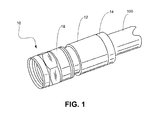
- FIG. 1 is an isometric view of an exemplary embodiment of a coaxial cable connector
- FIG. 2 is a cross-sectional view of an exemplary embodiment of the coaxial cable connector of the FIG. 1 ;
- FIG. 3 is a perspective view of the biasing element of the connector shown in FIG. 1 ;
- FIG. 4 is cross-sectional view of an alternative embodiment of the coaxial cable connector of the present invention.
- FIGS. 5A and 5B are perspective views of the biasing element of the connector shown in FIG. 4 ;
- FIG. 6A is a cross-sectional view of another alternative embodiment of the coaxial cable connector of the present invention.
- FIG. 6B is a perspective view of the biasing element shown in FIG. 6A ;
- FIG. 7A is a cross-sectional view of still another alternative embodiment of the coaxial cable connector of the present invention.
- FIG. 7B is a perspective view of the biasing element shown in FIG. 7A .
- FIG. 8 is a cross-sectional view of another exemplary embodiment of the coaxial cable connector of FIG. 1 in an unconnected configuration
- FIG. 9 is a cross-sectional view of the coaxial cable connector of FIG. 8 in a connected configuration
- FIG. 10A is an enlarged, isometric view of the exemplary biasing element of FIGS. 8 and 9 ;
- FIG. 10B is an enlarged axial view of the biasing element of FIG. 10A taken along line A of FIG. 8 ;
- FIG. 11 is a cross-sectional view of another exemplary biasing element
- FIG. 12A is an enlarged, isometric view of an exemplary biasing element of FIG. 11 ;
- FIG. 12B is an enlarged axial view of the biasing element of FIG. 12A taken along line A of FIG. 8 ;
- FIG. 13 is a cross-sectional view of yet another exemplary biasing element of the coaxial cable connector of FIG. 1 ;
- FIG. 14A is an enlarged, isometric view of the biasing element of FIG. 13 ;
- FIG. 14B is an enlarged axial view of the biasing element of FIG. 14A taken along line A of FIG. 13 .
- FIG. 15A is a cross-sectional view of another exemplary embodiment of the coaxial cable connector of FIG. 1 in an unconnected configuration
- FIG. 15B is a cross-sectional view of the coaxial cable connector of FIG. 15A in a connected configuration
- FIG. 16 is an enlarged, isometric view of the biasing element of FIGS. 15A-15B ;
- FIGS. 17-22 are isometric illustrations of alternative implementations of biasing element for use with the coaxial cable connector of FIG. 1 ;
- FIG. 23 is a cross-sectional view of another exemplary embodiment of the coaxial cable connector of FIG. 1 in an unconnected configuration.
- FIG. 24 is an enlarged cross-sectional view of the post of FIG. 23 .
- a large number of home coaxial cable installations are often done by “do-it yourself” laypersons who may not be familiar with torque standards associated with cable connectors. In these cases, the installer will typically hand-tighten the coaxial cable connectors instead of using a tool, which can result in the connectors not being properly seated, either upon initial installation, or after a period of use.
- the customer Upon immediately receiving a poor signal, the customer typically calls the CATV, MSO, satellite or telecommunication provider to request repair service. Obviously, this is a cost concern for the CATV, MSO, satellite and telecommunication providers, who then have to send a repair technician to the customer's home.
- FIGS. 1-2 depict an exemplary coaxial cable connector 10 consistent with embodiments described herein.
- connector 10 may include a connector body 12 , a locking sleeve 14 , an annular post 16 , and a rotatable nut 18 .
- connector body 12 may include an elongated, cylindrical member, which can be made from plastic, metal, or any suitable material or combination of materials.
- Connector body 12 may include a forward end 20 operatively coupled to annular post 16 and rotatable nut 18 , and a cable receiving end 22 opposite to forward end 20 .
- Cable receiving end 22 may be configured to insertably receive locking sleeve 14 , as well as a prepared end of a coaxial cable 100 in the forward direction as shown by arrow A in FIG. 2 .
- Cable receiving end 22 of connector body 12 may further include an inner sleeve engagement surface 24 for coupling with the locking sleeve 14 .
- inner sleeve engagement surface 24 is preferably formed with a groove or recess 26 , which cooperates with mating detent structure 28 provided on the outer surface of locking sleeve 14 .
- Locking sleeve 14 may include a substantially tubular body having a rearward cable receiving end 30 and an opposite forward connector insertion end 32 , movably coupled to inner sleeve engagement surface 24 of the connector body 12 .
- the outer cylindrical surface of locking sleeve 14 may be configured to include a plurality of ridges or projections 28 , which cooperate with groove or recess 26 formed in inner sleeve engagement surface 24 of the connector body 12 to allow for the movable connection of sleeve 14 to the connector body 12 , such that locking sleeve 14 is lockingly axially moveable along the direction of arrow A toward the forward end 20 of the connector body 12 from a first position, as shown, for example, in FIG.
- locking sleeve 14 When in the first position, locking sleeve 14 may be loosely retained in connector 10 . When in the second position, locking sleeve 14 may be secured within connector 10 . In some implementations, locking sleeve 14 may be detachably removed from connector 10 , e.g., during shipment, etc., by, for example, snappingly removing projections 28 from groove/recess 26 . Prior to installation, locking sleeve 14 may be reattached to connector body 12 in the manner described above.
- locking sleeve 14 may include a flanged head portion 34 disposed at the rearward cable receiving end 30 of locking sleeve 14 .
- Head portion 34 may include an outer diameter larger than an inner diameter of the body 12 and may further include a forward facing perpendicular wall 36 , which serves as an abutment surface against which the rearward end 22 of body 12 stops to prevent further insertion of locking sleeve 14 into body 12 .
- a resilient, sealing O-ring 37 may be provided at forward facing perpendicular wall 36 to provide a substantially water-tight seal between locking sleeve 14 and connector body 12 upon insertion of the locking sleeve within the body and advancement from the first position ( FIG. 2 ) to the second position ( FIG. 1 ).
- connector 10 may further include annular post 16 coupled to forward end 20 of connector body 12 .
- annular post 16 may include a flanged base portion 38 at its forward end for securing the post within annular nut 18 .
- Annular post 16 may also include an annular tubular extension 40 extending rearwardly within body 12 and terminating adjacent rearward end 22 of connector body 12 .
- the rearward end of tubular extension 40 may include a radially outwardly extending ramped flange portion or “barb” 42 to enhance compression of the outer jacket of the coaxial cable and to secure the cable within connector 10 .
- Tubular extension 40 of annular post 16 , locking sleeve 14 , and connector body 12 together define an annular chamber 44 for accommodating the jacket and shield of an inserted coaxial cable.
- annular nut 18 may be rotatably coupled to forward end 20 of connector body 12 .
- Annular nut 18 may include any number of attaching mechanisms, such as that of a hex nut, a knurled nut, a wing nut, or any other known attaching means, and may be rotatably coupled to connector body 12 for providing mechanical attachment of the connector 10 to an external device via a threaded relationship.
- nut 18 may include an annular flange 45 configured to fix nut 18 axially relative to annular post 16 and connector body 12 .
- a resilient sealing O-ring 46 may be positioned in annular nut 18 to provide a water resistant seal between connector body 12 , annular post 16 , and annular nut 18
- Connector 10 may be supplied in the assembled condition, as shown in the drawings, in which locking sleeve 14 is pre-installed inside rearward cable receiving end 22 of connector body 12 .
- a coaxial cable may be inserted through rearward cable receiving end 30 of locking sleeve 14 to engage annular post 16 of connector 10 in the manner described above.
- locking sleeve 14 may be first slipped over the end of a coaxial cable and the cable (together with locking sleeve 14 ) may subsequently be inserted into rearward end 22 of connector body 12 .
- locking sleeve 14 may be moved axially forward in the direction of arrow A from the first position (shown in FIG. 2 ) to the second position (shown in FIG. 1 ).
- advancing locking sleeve 14 from the first position to the second position may be accomplished with a suitable compression tool.
- the cable jacket is compressed within annular chamber 44 to secure the cable in connector 10 .
- connector 10 is ready for attachment to a port connector 48 (illustrated in FIGS. 9 and 15B ), such as an F-81 connector, of an external device.
- port connector 48 may include a substantially cylindrical body 50 having external threads 52 that match internal threads 54 of annular nut 18 . As will be discussed in additional detail below, retention force between annular nut 18 and port connector 48 may be enhanced by providing a substantially constant load force on the port connector 48 .
- connector 10 may include a biasing element or spring 200 extending outwardly beyond a forward face 56 of flanged base portion 38 of the post 16 for making resilient contact with a rearward face (element 58 in FIG. 9 ) of a mating connector port.
- Biasing element 200 may include a degree of flexure in that it is designed to deflect or deform in a rearward direction back toward forward face 56 of flanged base portion 38 .
- biasing element 200 is forced to compress to a certain degree as the rearward face of the connector port makes contact with the biasing element.
- biasing element 200 Such compression, or rearward deflection is desirable so that, should nut 18 loosen and the rearward face of the mating connector port begin to back away from forward face 56 of the post, the resilience of biasing element 200 will urge biasing element 200 to spring back to its initial form so that biasing element 200 will maintain contact with rearward face 58 of the mating connector port 48 .
- Biasing element 200 can take various forms, but in each form biasing element 200 is preferably made from a durable, resilient electrically conductive material, such as spring steel, for transferring the electrical signal from flanged base portion 38 to rearward face 58 of mating connector port 48 .
- biasing element 200 is in the form of a ring 210 having a cylindrical base portion 215 and a deflectable skirt portion 220 extending in a forward direction from a forward end of base portion 215 .
- deflectable skirt portion 220 extends in a direction radially inward from base portion 215
- the ring 410 shown in FIGS. 4 and 5 has a deflectable skirt portion 420 that extends in a direction radially outward from the base portion 415 .
- base portion 215 / 415 of the ring 210 / 410 is preferably press-fit within a circular groove 225 formed directly in forward face 56 of the post shoulder portion 38 .
- deflectable skirt 220 / 420 may extend beyond forward face 56 of the flanged base portion 38 a distance in the forward direction and is permitted to deflect or deform with respect to fixed base portion 215 toward and away from post forward face 56 .
- connector 10 may include a biasing element or spring 600 formed as a ring 610 having a cylindrical wall 615 with a retaining lip 620 formed on a rearward end of the wall and a reverse-bent, deflectable rim 625 formed on a forward end of the wall opposite the retaining lip.
- Cylindrical wall 615 may include an inner diameter closely matching an outer diameter of flanged base portion 38 and retaining lip 620 may extend in a direction radially inward from cylindrical wall 615 .
- Retaining lip 620 may be received in a peripheral groove 630 formed in the outer diametric surface of post shoulder portion 38 .
- retaining lip 620 can be formed with one or more slots 635 that enhance flexure of lip 620 to permit easy snap-fit insertion of flanged base portion 38 within ring 610 .
- the deflectable rim 625 of FIG. 6 may extend beyond forward face 56 of the post shoulder portion a distance in the forward direction and is permitted to deflect or deform with respect to the cylindrical wall 615 .
- the reverse-bent geometry of deflectable rim 625 allows the rim to collapse on itself when subjected to compression and return to its original shape as the compressive force is removed.
- the forward-most portion of rim 625 is permitted to move toward and away from post forward face 56 .
- connector 10 may include a biasing element or spring 700 formed as a ring 710 having a combination of the features of the rings 210 , 410 , and 610 described above.
- the ring 710 may include a cylindrical wall 715 with a retaining lip 720 formed on a rearward end of wall 715 similar to the ring 610 described above.
- a deflectable skirt 725 may be formed on the forward end of the wall opposite retaining lip 720 .
- cylindrical wall 715 may include an inner diameter closely matching the outer diameter of post shoulder portion 38 and retaining lip 720 may extend in a direction radially inward from cylindrical wall 715 .
- Retaining lip 720 may be received in a peripheral groove 730 formed in the outer diametric surface of the flanged base portion 38 .
- retaining lip 720 can again be formed with one or more slots 735 that enhance flexure of lip 720 to permit easy snap-fit insertion of the flanged base portion 38 within the ring 710 .
- deflectable skirt 725 of ring 710 may extend in a forward direction from a forward end of cylindrical wall 715 and may also extend in a direction radially inward from cylindrical wall 715 .
- deflectable skirt 725 may project at an angle of approximately 45 degrees relative to forward surface 56 of annular post 16 .
- deflectable skirt 725 may project approximately 0.039 inches from the forward edge of ring 710 .
- connector 10 may allows for up to 360 degree “back-off” rotation of the nut 18 on a terminal, without signal loss.
- the biasing element may help to maintain electrical continuity even if the nut is partially loosened.
- maintaining electrical contact between coaxial cable connector 10 and the signal contact of port connector 48 is improved by a factor of 400-500%, as compared with prior art connectors.
- FIGS. 8-10B another alternative implementation of a connector 10 is illustrated.
- the embodiment of FIGS. 8-10B is similar to the embodiment illustrated in FIG. 2 , and similar reference numbers are used where appropriate.
- retention force between annular nut 18 and port connector 48 may be enhanced by providing a substantially constant load force on the port connector 48 .
- flanged base portion 38 of annular post 16 may be configured to include a notched configuration that includes an annular notch portion 800 and an outwardly extending lip portion 805 , with annular notch portion 800 having a smaller outside diameter than lip portion 805 .
- Annular notch portion 800 may be configured to retain a biasing element 810 .
- the outside diameter of a forward surface of lip portion 805 may beveled, chamfered, or otherwise angled, such that a forwardmost portion of lip portion 805 has a smaller inside diameter than a readwardmost portion of lip portion 805 .
- forwardmost portion of lip portion 805 may include an outside 25° radius curve. Other suitable degrees of curvature may be used. Such a configuration may enable efficient assembly of biasing element 810 with annular post 16 , as described in additional detail below.
- biasing element 810 may include an inside 25° radius curve to match the outside curve on lip portion 805 .
- Biasing element 810 may include a conductive, resilient element configured to provide a suitable biasing force between annular post 16 and rearward surface 58 of port connector 48 .
- the conductive nature of biasing element 810 may facilitate passage of electrical and radio frequency (RF) signals from annular post 16 to port connector 48 at varying degrees of insertion relative to port connector 48 and connector 10 .
- RF radio frequency
- biasing element 810 may include a conical spring having first, substantially cylindrical attachment portion 815 configured to engagingly surround at least a portion of flanged base portion 38 , and a second portion 820 having a number of slotted resilient fingers 825 configured in a substantially conical manner with respect to first portion 815 .
- a forward end of second portion 820 may have a smaller diameter than the diameter of rearward end of second portion 820 and first portion 815 .
- first portion 815 and second portion 820 may transition via an inside curve that substantially matches an outside curve of lip portion 805 . By providing substantially matching inside and outside curves, over stressing of the bending moment of biasing element 810 may be reduced.
- resilient fingers 825 may be equally spaced around a circumference of biasing element 810 , such that biasing element 810 includes eight resilient fingers 825 , with a centerline of each finger 825 being positioned approximately 45° from its adjacent fingers 825 .
- the number of resilient fingers 825 illustrated in FIGS. 10A and 10B is exemplary and any suitable number of resilient fingers 825 may be used in a manner consistent with implementations described herein.
- First portion 815 of biasing element 810 may be configured to have an inside diameter substantially equal to the outside diameter of lip portion 805 .
- First portion 815 may be further configured to include a number of attachment elements 830 designed to engage notch portion 800 of flanged base portion 38 .
- attachment elements 830 may include a number of dimples or detents 835 formed in first portion 815 , such that an interior of each detent 835 projects within the interior diameter of first portion 815 .
- Detents 835 may be referred to as “lantzes” or “bump lantzes” and may be formed by forcefully applying a suitably shaped tool, such as an awl, hammer, etc., to the outside diameter of first portion 815 .
- first portion 815 may include eight detents 835 formed around a periphery of first portion 815 .
- a single continuous detent may be formed around the periphery of first portion 815 to engage notch portion 800 .
- biasing element 810 may be formed of a metallic material, such as spring steel, having a thickness of approximately 0.008 inches. In other implementations, biasing element 810 may be formed of a resilient, elastomeric, rubber, or plastic material, impregnated with conductive particles.
- first portion 815 of biasing element 810 may be engaged with flanged base portion 38 , e.g., by forcing the inside diameter of first portion 815 over the angled outside diameter of lip portion 805 .
- detents 835 engage annular notch portion 800 , thereby retaining biasing element 810 to annular post 16 , while enabling biasing element 810 to freely rotate with respect to annular post 16 .
- slotted resilient fingers 825 of biasing element 810 may extend a length “z” beyond forward surface 56 of annular post 16 .
- rearward surface 58 of port connector 48 may come into contact with resilient fingers 825 .
- biasing element 81 may enable effective transmission of electrical and RF signals from port connector 48 to annular post 16 even when separated by distance z, effectively increasing the reference plane of connector 10 .
- the above-described configuration enables a functional gap or “clearance” of less than or equal to approximately 0.043 inches, for example 0.033 inches, between the reference planes, thereby enabling approximately 360 degrees or more of “back-off” rotation of annular nut 18 relative to port connector 48 while maintaining suitable passage of electrical and/or RF signals.
- port connector 48 may cause compression of resilient fingers 825 , thereby providing a load force between flanged base portion 38 and port connector 48 and decreasing the distance between rearward surface 58 of port connector 48 and forward surface 56 of annular post 16 .
- This load force may be transferred to threads 52 and 54 , thereby facilitating constant tension between threads 52 and 54 and decreasing the likelihood that port connector 48 will become loosened from connector 10 due to external forces, such as vibrations, heating/cooling, etc.
- the annular post 16 may be incorporated into a coaxial cable between the cable foil and the cable braid and may function to carry the RF signals propagated by the coaxial cable.
- post 16 makes contact with the reference plane of the mating connector (e.g., port connector 48 ).
- the reference plane of the mating connector e.g., port connector 48
- biasing element 810 is able to ensure electrical and RF contact at the reference plane of port connector 48 .
- the stepped nature of post 16 enables compression of biasing element 810 , while simultaneously supporting direct interfacing between post 16 and port connector 48 . Further, compression of biasing element 810 provides equal and opposite biasing forces between the internal threads of nut 18 and the external threads of port connector 48 .
- flanged base portion 38 may include annular notch portion 1100 and an outwardly extending lip portion 1105 , with annular notch portion 1100 having a smaller outside diameter than lip portion 1105 as described above in FIGS. 8 and 9 .
- Annular notch portion 1100 may be configured to retain a biasing element 1110 .
- the outside diameter of a forward surface of lip portion 1105 may be beveled, chamfered, or otherwise angled, such that a forwardmost portion of lip portion 1105 has a smaller inside diameter than a readwardmost portion of lip portion 1105 .
- forwardmost portion of lip portion 1105 may include an outside 25° radius curve, although any suitable degrees of curvature may be used.
- biasing element 1110 may include an inside 25° radius curve to match the outside curve on lip portion 1105 .
- biasing element 1110 may include a conductive, resilient element configured to provide a suitable biasing force between annular post 16 and rearward surface (e.g., rearward surface 58 of FIG. 9 ) of a port connector (e.g., port connector 48 of FIG. 9 ).
- the conductive nature of biasing element 1110 may facilitate passage of electrical and RF signals from annular post 16 to port connector 48 at varying degrees of insertion relative to port connector 48 and connector 10 .
- biasing element 1110 may include a conical spring having a substantially cylindrical first portion 1115 configured to engagingly surround at least a portion of flanged base portion 38 , and a second portion 1120 having a number of slotted resilient fingers 1125 configured in a curved, substantially conical manner with respect to first portion 1115 .
- a forward end of second portion 1120 may have a smaller diameter than the diameter of rearward end of second portion 1120 and first portion 1115 .
- resilient fingers 1125 may be formed in a radially curving manner, such that each finger 1125 extends radially along its length. Resilient fingers 1125 may be equally spaced around the circumference of biasing element 1110 , such that biasing element 1110 includes eight, equally spaced, resilient fingers.
- the number of resilient fingers 1125 disclosed in FIGS. 12A and 12B is exemplary and any suitable number of resilient fingers 1125 may be used in a manner consistent with implementations described herein.
- First portion 1115 of biasing element 1110 may be configured to have an inside diameter substantially equal to the outside diameter of lip portion 1105 .
- First portion 1115 may be further configured to include a number of attachment elements 1130 designed to engage notch portion 1110 of flanged base portion 38 .
- attachment elements 1130 may include a number of dimples or detents 1135 formed in first portion 1115 , such that an interior of each detent 1135 projects within the interior diameter of first portion 1115 .
- Detent 1135 may be formed by forcefully applying a suitably shaped tool, such as an awl or the like, to the outside diameter of first portion 1115 .
- first portion 1115 may include four detents 1135 formed around a periphery thereof.
- biasing element 1110 may be formed of a metallic material, such as spring steel, having a thickness of approximately 0.008 inches. In other implementations, biasing element 1110 may be formed of a resilient, elastomeric, rubber, or plastic material, impregnated with conductive particles. Furthermore, in an exemplary implementation, biasing element 1110 may have an inside diameter of approximately 0.314 inches, with first portion 1115 having a length of approximately 0.080 inches and second portion 1120 having an axial length of approximately 0.059 inches. Each of radially curved fingers 1125 may have an angle of approximately 45° relative to an axial direction of biasing element 1110 . The forward end of second portion 1120 may have a diameter of approximately 0.196 inches and the rearward end of second portion 1120 may have a diameter of approximately 0.330 inches. Each dimple or detent 1135 may have a radius of approximately 0.020 inches.
- first portion 1115 of biasing element 1110 may be engaged with flanged base portion 38 , e.g., by forcing the inside diameter of first portion 1115 over the angled outside diameter of lip portion 1105 .
- detents 1135 engage annular notch portion 1100 , thereby retaining biasing element 1110 to annular post 16 , while enabling biasing element 1110 to freely rotate with respect to annular post 16 .
- slotted resilient fingers 1125 of biasing element 1110 may extend a length “z” beyond forward surface 56 of annular post 16 .
- rearward surface 58 of port connector 48 may come into contact with resilient fingers 1125 .
- biasing element 1110 may enable effective transmission of electrical and RF signals from port connector 48 to annular post 16 even when separated by distance z, effectively increasing the reference plane of connector 10 .
- port connector 48 may cause compression of resilient fingers 1125 , thereby providing a load force between flanged base portion 38 and port connector 48 and decreasing the distance between rearward surface 58 of port connector 48 and forward surface 56 of annular post 16 .
- This load force may be transferred to threads 52 and 54 , thereby facilitating constant tension between threads 52 and 54 and decreasing the likelihood that port connector 48 will become loosened from connector 10 due to external forces, such as vibrations, heating/cooling, etc.
- flanged base portion 38 may be substantially cylindrical and may not include an annular notch portion.
- Flanged base portion 38 may include annular flange 45 having a forward surface 1300 and a body portion 1305 having forward surface 56 .
- the outside diameter of forward surface 56 of body portion 1305 may be beveled, chamfered, or otherwise angled, such that a forwardmost portion of body portion 1305 has a smaller inside diameter than a readwardmost portion of body portion 1305 .
- forwardmost portion of body portion 1305 may include an outside 25° radius curve, although any other degrees of curvature may be used.
- biasing element 1315 may include an inside 25° radius curve to match the outside curve on body portion 1305 .
- biasing element 1315 may include a conductive, resilient element configured to provide a suitable biasing force between annular post 16 and rearward surface (e.g., rearward surface 58 of FIG. 9 ) of a port connector (e.g., port connector 48 of FIG. 9 ).
- the conductive nature of biasing element 1315 may facilitate passage of electrical and RF signals from annular post 16 to port connector 48 at varying degrees of insertion relative to port connector 48 and connector 10 .
- biasing element 1315 may include a conical spring having a first, substantially cylindrical attachment portion 1320 configured to engagingly surround at least a portion of body portion 1305 of flanged base portion 38 , and a second portion 1325 having a number of slotted resilient fingers 1330 configured in a substantially conical manner with respect to first portion 1320 .
- a forward end of second portion 1325 may have a smaller diameter than the diameter of rearward end of second portion 1325 and first portion 1320 .
- First portion 1320 of biasing element 1315 may be configured to have an inside diameter substantially equal to the outside diameter of body portion 1305 .
- first portion 1320 of biasing element 1315 may include a flange 1335 extending annularly from its rearward end. Flange 1335 may be configured to enable biasing element 1315 to be press-fit by an appropriate tool or device about body portion 1305 , such that biasing element 1315 is frictionally retained against body portion 1305 .
- resilient fingers 1330 may be equally spaced around a circumference of biasing element 1315 , such that biasing element 1315 includes eight resilient fingers 1330 , with a centerline of each finger 1330 being positioned approximately 45° from its adjacent fingers 1330 .
- the number of resilient fingers 1330 illustrated in FIGS. 14A and 14B is exemplary and any suitable number of resilient fingers 1330 may be used in a manner consistent with implementations described herein.
- biasing element 1315 may be formed of a metallic material, such as spring steel, having a thickness of approximately 0.008 inches. In other implementations, biasing element 1315 may be formed of a resilient, elastomeric, rubber, or plastic material, impregnated with conductive particles. Furthermore, in an exemplary implementation, biasing element 1315 may have an inside diameter of approximately 0.285 inches, with first portion 1320 having a length of approximately 0.080 inches and second portion 1325 having an axial length of approximately 0.059 inches. Each of resilient fingers 1330 may have an angle of approximately 45° relative to an axial direction of biasing element 1315 . The forward end of second portion 1325 may have a diameter of approximately 0.196 inches and the rearward end of second portion 1325 may have a diameter of approximately 0.301 inches.
- first portion 1320 of biasing element 1315 may be engaged with flanged base portion 38 , e.g., by forcing the inside diameter of first portion 1320 over the angled outside diameter of body portion 1305 .
- Continued rearward movement of biasing element 1315 relative to body portion 1305 e.g., via force exerted on flange 1335 , may cause biasing element 1315 to engage body portion 1305 , thereby retaining biasing element 1315 to annular post 16 .
- slotted resilient fingers 1330 of biasing element 1315 may extend a length “z” beyond forward surface 56 of annular post 16 .
- rearward surface 58 of port connector 48 may come into contact with resilient fingers 1330 .
- rearward surface 58 of port connector 48 may be separated from forward surface 56 of annular post 16 by the distance “z.”
- biasing element 1315 may enable effective transmission of electrical and RF signals from port connector 48 to annular post 16 even when separated by distance z, effectively increasing the reference plane of connector 10 .
- Continued insertion of port connector 48 into connector 10 may cause compression of resilient fingers 1330 , thereby providing a load force between flanged base portion 38 and port connector 48 and decreasing the distance between rearward surface 58 of port connector 48 and forward surface 56 of annular post 16 .
- This load force may be transferred to threads 52 and 54 , thereby facilitating constant tension between threads 52 and 54 and decreasing the likelihood that port connector 48 will become loosened from connector 10 due to external forces, such as vibrations, heating/cooling, etc.
- flanged base portion 38 may be configured to include a notched configuration that includes an annular notch portion 1500 and an outwardly extending lip portion 1505 , with annular notch portion 1500 having a smaller outside diameter than lip portion 1505 .
- Annular notch portion 1500 may be configured to retain a biasing element 1510 therein.
- the outside diameter of a forward surface of lip portion 1505 may beveled, chamfered, or otherwise angled, such that a forwardmost portion of lip portion 1505 has a smaller inside diameter than a readwardmost portion of lip portion 1505 .
- forwardmost portion of lip portion 1505 may include an outside 25° radius curve, although other degrees of curvature may be used in other implementations.
- biasing element 1510 may include an inside 25° radius curve to match the outside curve on lip portion 1505 .
- biasing element 1510 may include a conductive, resilient element configured to provide a suitable biasing force between annular post 16 and rearward surface 58 of port connector 48 (as shown in FIG. 15B ).
- the conductive nature of biasing element 1510 may facilitate passage of electrical and radio frequency (RF) signals from annular post 16 to port connector 48 at varying degrees of insertion relative to port connector 48 and connector 10 .
- RF radio frequency
- biasing element 1510 may include a stamped, multifaceted spring having a first, substantially octagonal attachment portion 1515 configured to engagingly surround at least a portion of flanged base portion 38 , and a second, resilient portion 1520 having a number angled or beveled spring surfaces extending in a resilient relationship from attachment portion 1515 .
- Second, resilient portion 1520 may include an opening therethrough corresponding to tubular extension 40 in annular post 16 .
- biasing element 1510 may be formed of spring steel or stainless steel, with second portion 1520 being formed integrally with first portion 1515 and bent more than 90° relative to first portion 1515 .
- FIG. 16 illustrates an exemplary biasing element 1510 taken along the line B-B in FIG. 15A .
- biasing element 1510 may include an octagonal outer ring 1600 integrally formed with a resilient portion 1605 having an opening 1610 extending therethrough.
- biasing element 1510 may be initially cut (e.g., die cut) from a sheet of conductive material, such as steel, spring steel, or stainless steel having a thickness of approximately 0.008 inches.
- Octagonal outer ring 1600 may be bent downward from resilient portion 1605 until outer ring 1600 is substantially perpendicular to a plane extending across an upper surface of resilient portion 1605 .
- Angled or beveled surfaces 1615 may be formed in resilient portion 1605 , such that differences in an uncompressed thickness of resilient portion 1605 are formed.
- resilient portion 1605 may be stamped or otherwise mechanically deformed to form a number of angled surfaces, where a lowest point in at least two of the angled surfaces are spaced a predetermined distance in a vertical (or axial) direction (e.g., 0.04 inches) from the upper edge of octagonal outer ring 1600 .
- a vertical (or axial) direction e.g. 0.04 inches
- second portion 1520 extends in an angled manner from a forward edge of attachment portion 1515 . Accordingly, in a first position (in which port connector 48 is not attached to connector 10 ), the angled nature of second portion 1520 causes second portion 1520 to abut a forward edge 56 of annular post 16 , while the forward edge of attachment portion 1515 is separated from forward edge 56 of annular post 16 , as depicted by the length “z” in FIG. 15A .
- First portion 1515 of biasing element 1510 may be configured to have a minimum inside width (e.g., between opposing octagonal sections) substantially equal to the outside diameter of lip portion 1505 .
- First portion 1515 may be further configured to include a number of attachment elements 1620 designed to engage notch portion 1500 of flanged base portion 38 .
- attachment elements 1620 may include a number of detents or tabs 1625 formed in first portion 1515 , such that an interior of each tab 1625 projects within the interior width of first portion 1515 .
- first portion 1515 may include four tabs 1625 (two of which are shown in FIG. 16 ) formed around a periphery of first portion 1515 . In another exemplary implementation (not shown), more or fewer tabs 1625 may be formed around the periphery of first portion 1515 to engage notch portion 1500 .
- first portion 1515 of biasing element 1510 may be engaged with flanged base portion 38 , e.g., by forcing first portion 1515 over the angled outside diameter of lip portion 1505 .
- first portion 1515 may be engaged with flanged base portion 38 , e.g., by forcing first portion 1515 over the angled outside diameter of lip portion 1505 .
- detents 1625 engage annular notch portion 1500 , thereby retaining biasing element 1510 to annular post 16 , while enabling biasing element 1510 to freely rotate with respect to annular post 16 .
- abutment of second portion 1520 of biasing element 1510 may cause the forward edge of attachment portion 1515 to extend length “z” beyond forward surface 56 of annular post 16 .
- rearward surface 58 of port connector 48 may come into contact with the forward edge of attachment portion 1515 .
- biasing element 1510 may enable effective transmission of electrical and RF signals from port connector 48 to annular post 16 even when separated by distance z, effectively increasing the reference plane of connector 10 .
- the above-described configuration enables a functional gap or “clearance” of less than or equal to approximately 0.040 inches, for example 0.033 inches, between the reference planes, thereby enabling approximately 360 degrees or more of “back-off” rotation of annular nut 18 relative to port connector 48 while maintaining suitable passage of electrical and/or RF signals.
- port connector 48 may cause compression of second, angled portion 1520 , thereby providing a load force between flanged base portion 38 and port connector 48 and decreasing the distance between rearward surface 58 of port connector 48 and forward surface 56 of annular post 16 .
- This load force may be transferred to threads 52 and 54 , thereby facilitating constant tension between threads 52 and 54 and decreasing the likelihood that port connector 48 will become loosened from connector 10 due to external forces, such as vibrations, heating/cooling, etc.
- the annular post 16 may be incorporated into a coaxial cable between the cable foil and the cable braid and may function to carry the RF signals propagated by the coaxial cable.
- post 16 makes contact with the reference plane of the mating connector (e.g., port connector 48 ).
- the reference plane of the mating connector e.g., port connector 48
- biasing element 1510 is able to ensure electrical and RF contact at the reference plane of port connector 48 .
- the stepped nature of post 16 enables compression of biasing element 1510 , while simultaneously supporting direct interfacing between post 16 and port connector 48 . Further, compression of biasing element 1510 provides equal and opposite biasing forces between the internal threads of nut 18 and the external threads of port connector 48 .
- FIGS. 17-22 alternative implementations of biasing elements are shown.
- Each of the embodiments illustrated in FIGS. 17-22 are configured for attachment to notched portion 1500 in annular post 16 in a manner similar to that described above in relation to FIGS. 15A-16 .
- FIG. 17 illustrates an exemplary biasing element 1700 consistent with embodiments described herein.
- biasing element 1700 similar to biasing element 1510 described above in relation to FIGS. 15A-16 , includes a substantially octagonal attachment portion 1705 having six angled sides 1710 - 1 to 1710 - 6 and a resilient center portion 1715 having a central opening 1720 provided therein.
- attachment portion 1705 of FIG. 17 does not extend substantially throughout each of the eight possible sides in its octagonal perimeter. Instead, as illustrated in FIG.
- attachment portion 1705 may include six of the octagonal perimeters sides 1710 - 1 to 1710 - 6 , with opposing seventh and eighth sides not including corresponding attachment portion sides. Reducing the number of sides provided may decrease expense without detrimentally affecting performance.
- attachment portion 1705 and center portion 1715 may be integrally formed from a sheet of resilient material, such as spring or stainless steel. As illustrated in FIG. 17 , attachment portion 1705 may be formed by bending sides 1710 - 1 to 1710 - 6 substantially perpendicular relative to center portion 1715 . In one embodiment, attachment portion 1705 may be connected to center portion 1715 via bends in sides 1710 - 2 and 1710 - 5 .
- Resilient center portion 1715 may include a curved or U-shaped configuration, configured to provide center portion 1715 with a low portion 1725 disposed between sides 1710 - 2 and 1710 - 4 and high portions 1730 adjacent sides 1710 - 4 and 1710 - 6 . That is, resilient center portion 1715 is formed to create a trough between opposing portions of attachment portion 1705 .
- low portion 1725 and high portions 1730 When the connector is in a first position (in which port connector 48 is not attached to connector 10 ), the relationship between low portion 1725 and high portions 1730 causes low portion 1725 of biasing element 1700 to abut a forward edge of annular post 16 , while high portions 1730 of biasing element 1700 are separated from the forward edge of annular post 16 by a distance equivalent to the depth of the trough formed between low portion 1725 and high portions 1730 .
- Attachment portion 1705 of biasing element 1700 may be configured to have a minimum inside width (e.g., between opposing octagonal sections) substantially equal to the outside diameter of lip portion 1505 .
- Attachment portion 1705 may be further configured to include a number of attachment elements 1735 designed to engage notch portion 1500 of flanged base portion 38 .
- attachment elements 1735 may include a number of detents or tabs 1740 formed in attachment portion 1705 , such that an interior of each tab 1740 projects within the interior width of attachment portion 1705 .
- attachment portion 1705 may include four tabs 1740 (two of which are shown in FIG. 17 ) formed around a periphery of attachment portion 1705 . In another exemplary implementation (not shown), more or fewer tabs 1740 may be formed around the periphery of attachment portion 1705 to engage notch portion 56 in annular post 16 .
- attachment portion 1705 of biasing element 1700 may be engaged within flanged base portion 38 , e.g., by forcing attachment portion 1705 over the angled outside diameter of lip portion 1505 .
- Continued rearward movement of biasing element 1700 relative to flanged base portion 38 causes tabs 1740 to engage annular notch portion 1500 , thereby retaining biasing element 1700 to annular post 16 , while enabling biasing element 1700 to freely rotate with respect to annular post 16 .
- FIG. 18 illustrates an exemplary biasing element 1800 consistent with embodiments described herein.
- biasing element 1800 similar to biasing element 60 in FIGS. 15A-16 , may include a substantially octagonal attachment portion 1805 having angled sides 1810 - 1 to 1810 - 8 and a resilient center portion 1815 having a central opening 1820 provided therein.
- Resilient center portion 1815 may be formed substantially perpendicularly with attachment portion 1805 .
- attachment portion 1805 may include a number of tabbed portions 1825 - 1 to 1825 - 4 integrally formed with at least some of angled sides 1810 - 1 to 1810 - 8 .
- tabbed portion 1825 - 1 may be integrally formed with angled side 1810 - 3
- tabbed portion 1825 - 2 may be integrally formed with angled side 1810 - 5
- tabbed portion 1825 - 3 may be integrally formed with angled side 1810 - 7
- tabbed portion 1825 - 4 may be integrally formed with angled side 1810 - 1 .
- Tabbed portions 1825 - 1 to 1825 - 4 may include resilient tabs 1830 - 1 to 1830 - 4 , respectively, having an angled surface and configured to resiliently project from a first end 1835 adjacent to the top of angled sides 1810 to a second end 1840 distal from, and lower than, first end 1835 .
- second distal end 1840 is approximately 0.04′′ lower (e.g., in a vertical or axial direction) than first end 1835 of resilient tabs 1830 - 1 to 1830 - 4 .
- the angled surfaces of resilient tabs 1830 - 1 to 1830 - 4 may be configured to provide the biasing force between annular post 16 and port connector 48 . As shown in FIG. 18 , the angled surfaces of resilient tabs 1830 - 1 to 1830 - 4 may be configured in such a manner as to render central opening 1820 substantially rectangular in shape.
- resilient tabs 1830 - 1 to 1830 - 4 may project from respective angled sides 1810 - 3 , 1810 - 5 , 1810 - 7 , and 1810 - 1 in a parallel relationship to an adjacent angled side (e.g., side 1810 - 2 , 1810 - 4 , 1810 - 6 , or 1810 - 8 ).
- tabbed portion 1825 - 2 may project from angled side 1810 - 5 with resilient tab 1830 - 2 projecting from tabbed portion 1825 - 2 parallel to angled side 1810 - 4 .
- attachment portion 1805 and central portion 1815 may be stamped from a sheet of resilient material, such as spring or stainless steel.
- the relationship between second ends 1840 of resilient tabs 1830 - 1 to 1830 - 4 and first ends 1835 of resilient tabs 1830 - 1 to 1830 - 4 may cause second ends 1840 of resilient tabs 1830 - 1 to 1830 - 4 to abut a forward edge of annular post 16 , while first ends 1835 of resilient tabs 1830 - 1 to 1830 - 4 are separated from the forward edge of annular post 16 .
- Attachment portion 1805 of biasing element 1800 may be configured to have a minimum inside width (e.g., between opposing octagonal sections) substantially equal to the outside diameter of lip portion 1505 .
- Attachment portion 505 may be further configured to include a number of attachment elements designed to engage notch portion 1500 of flanged base portion 38 (not shown in FIG. 18 ). Similar to the attachment elements disclosed above in relation to FIG. 17 , the attachment elements of the current embodiment may also include a number of tabs, detents, or lantzes for engaging notch portion 1500 in annular post 16 and retaining biasing element 1800 to annular post 16 .
- attachment portion 1805 of biasing element 1800 may be engaged within flanged base portion 38 , e.g., by forcing attachment portion 505 over the angled outside diameter of lip portion 1505 .
- Continued rearward movement of biasing element 1800 relative to flanged base portion 38 causes the attachment elements to engage annular notch portion 1500 , thereby retaining biasing element 1800 to annular post 16 , while enabling biasing element 1800 to freely rotate with respect to annular post 16 .
- FIG. 19 illustrates an exemplary biasing element 1900 consistent with embodiments described herein.
- biasing element 1900 similar to biasing element 1510 in FIGS. 15A-16 , may include a first, substantially cylindrical attachment portion 1905 and a resilient center portion 1910 having a central opening 1913 provided therein.
- Resilient center portion 1910 may be formed substantially perpendicularly to cylindrical attachment portion 1905 .
- resilient center portion 1910 may be integrally formed with substantially cylindrical attachment portion 1905 and may include a number of arcuate tabbed portions 1915 - 1 to 1915 - 3 connected to attachment portion 1905 by spoke portions 1920 - 1 to 1920 - 3 .
- Attachment portion 1905 may also include a center support ring 1925 attached to an inside edge of spoke portions 1920 - 1 to 1920 - 3 .
- Central support ring 1925 may be positioned in a plane substantially level (e.g., in an axial direction) with spoke portions 1920 and an upper edge of attachment portion 1905 .
- Arcuate tabbed portions 1915 - 1 to 1915 - 3 may include resilient tabs 1930 - 1 to 1930 - 3 , respectively, having an angled surface and configured to resiliently project from spoke portions 1920 - 1 to 1920 - 3 , respectively.
- a first end 1935 is radially connected to spoke portion 1920 - 1 to 1920 - 3 , respectively.
- Each tab 1930 - 1 to 1930 - 3 extends from first end 1935 to a second end 1940 distal from, and lower than, first end 1935 .
- second distal end 1940 is approximately 0.04′′ lower than a respective spoke portion 1920 (e.g., in a vertical or axial direction).
- the angled surfaces of resilient tabs 1930 - 1 to 1930 - 3 may be configured to provide the biasing force between annular post 16 and port connector 48 .
- attachment portion 1905 and central portion 1915 may be stamped from a sheet of resilient material, such as spring or stainless steel.
- Attachment portion 1905 of biasing element 1900 may be configured to have a minimum inside diameter substantially equal to the outside diameter of lip portion 1505 .
- Attachment portion 1905 may be further configured to include a number of attachment elements designed to engage notch portion 1500 of flanged base portion 38 (not shown in FIG. 19 ). Similar to the attachment elements disclosed above in relation to FIG. 16 , the attachment elements of the embodiment illustrated in FIG. 19 may also include a number of tabs, detents, or lantzes for engaging notch portion 1500 in annular post 16 and retaining biasing element 1900 to annular post 16 .
- attachment portion 1905 of biasing element 1900 may be engaged within flanged base portion 38 , e.g., by forcing attachment portion 1905 over the angled outside diameter of lip portion 1505 .
- Continued rearward movement of biasing element 1900 relative to flanged base portion 38 causes the attachment elements to engage annular notch portion 1500 , thereby retaining biasing element 1900 to annular post 16 , while enabling biasing element 1900 to freely rotate with respect to annular post 16 .
- FIG. 20 illustrates an exemplary biasing element 2000 consistent with embodiments described herein.
- the embodiment of FIG. 20 is similar to the embodiment illustrated in FIG. 19 , and similar reference numbers are used where appropriate.
- spoke portions 2000 - 1 to 2000 - 3 in FIG. 20 are substantially larger than spoke portions 1920 - 1 to 1920 - 3 in FIG. 19 .
- resilient tabs 2005 - 1 to 2005 - 3 in FIG. 20 are shorter in length than resilient tabs 1930 - 1 to 1930 - 3 .
- Increasing the size of spoke portions 1930 relative to tabs 2005 may provide increased strength in biasing element 2000 .
- FIG. 21 illustrates an exemplary biasing element 2100 consistent with embodiments described herein.
- biasing element 2100 similar to biasing element 1900 in FIG. 19 , may include a first, substantially cylindrical attachment portion 2105 and a resilient center portion 2110 having a central opening 2115 provided therein.
- Resilient center portion 2110 may be formed substantially perpendicularly to cylindrical attachment portion 2105 .
- resilient center portion 2110 may be integrally formed with substantially cylindrical attachment portion 2105 and may include a circular hub portion 2120 that includes a number of radially spaced tab openings 2125 - 1 to 2125 - 4 formed therein.
- a number of arcuate, axially projecting tabbed portions 2130 - 1 to 2130 - 4 may resiliently depend from circular hub portion 2120 in tab openings 2125 - 1 to 2125 - 4 , respectively.
- Tabbed portions 2130 - 1 to 2130 - 4 may include resilient tabs 2135 - 1 to 2135 - 4 , respectively, having an angled surface and configured to resiliently project within tab openings 2125 - 1 to 2125 - 4 , respectively.
- a first end 2140 is axially connected to an outside edge of tab openings 2125 - 1 to 2125 - 4 , respectively.
- Each tab 2135 - 1 to 2135 - 4 extends from first end 2140 to a second end 2145 distal from, and lower than, first end 2140 in an axial direction.
- second distal end 2145 is approximately 0.04′′ lower than circular hub portion 2120 .
- the angled surfaces of resilient tabs 2135 - 1 to 2135 - 4 may be configured to provide the biasing force between annular post 16 and port connector 48 .
- attachment portion 2105 and central portion 2110 may be stamped from a sheet of resilient material, such as spring or stainless steel.
- Attachment portion 2105 of biasing element 2100 may be configured to have a minimum inside diameter substantially equal to the outside diameter of lip portion 1505 .
- Attachment portion 2105 may be further configured to include a number of attachment elements designed to engage notch portion 1500 of flanged base portion 38 (not shown in FIG. 21 ). Similar to the attachment elements disclosed above in relation to FIG. 16 , the attachment elements of the current embodiment may also include a number of tabs, detents, or lantzes for engaging notch portion 1500 in annular post 16 and retaining biasing element 2100 to annular post 16 .
- attachment portion 2105 of biasing element 2100 may be engaged within flanged base portion 38 , e.g., by forcing attachment portion 2105 over the angled outside diameter of lip portion 1505 .
- Continued rearward movement of biasing element 2100 relative to flanged base portion 38 causes the attachment elements to engage annular notch portion 1500 , thereby retaining biasing element 2100 to annular post 16 , while enabling biasing element 2100 to freely rotate with respect to annular post 16 .
- FIG. 22 illustrates an exemplary biasing element 2200 consistent with embodiments described herein.
- biasing element 2200 may include a first, substantially cylindrical attachment portion 2205 and a resilient center portion 2210 having a central opening 2215 provided therein.
- resilient center portion 2210 may be integrally formed with substantially cylindrical attachment portion 2205 and may include a number of resilient spring elements 2220 - 1 to 2220 - 4 formed therein.
- resilient spring elements 2220 - 1 to 2220 - 4 may be separated from each other by slots 2225 - 1 to 2225 - 4 .
- spring elements 2220 may each include a spring opening 2230 therein (individually, spring openings 2230 - 1 to 2230 - 4 ).
- Each of spring elements 2220 may be formed in an angled or curved configuration, such that an inside edge of each spring element 2220 (e.g., the edge toward central opening 2215 ) may be raised relative to an outside edge of each spring element 2220 .
- the inside edge of spring elements 2220 may be raised approximately 0.04′′-0.05′′ in an axial direction relative to the outside edge of spring elements 2220 .
- the angled or curved surfaces of spring elements 2220 may be configured to provide the biasing force between annular post 16 and port connector 48 .
- attachment portion 2205 and resilient portion 2210 may be stamped from a sheet of resilient material, such as spring or stainless steel.
- each spring element 2220 When the connector is in a first position (in which port connector 48 is not attached to connector 10 ), the relationship between the inside edge of each spring element 2220 to the outside edge of each spring element 2220 may cause the outside edge to abut a forward edge of annular post 16 , while the inside edge is separated from the forward edge of annular post 16 .
- Attachment portion 2205 of biasing element 2200 may be configured to have a minimum inside diameter substantially equal to the outside diameter of lip portion 1505 .
- Attachment portion 2205 may be further configured to include a number of attachment elements 2235 designed to engage notch portion 1500 of flanged base portion 38 . Similar to the attachment elements disclosed above in relation to FIG. 16 , attachment elements 2235 may include a number of tabs, detents, or lantzes for engaging notch portion 1500 in annular post 16 and retaining biasing element 2200 to annular post 16 .
- attachment portion 2205 of biasing element 2200 may be engaged within flanged base portion 38 , e.g., by forcing attachment portion 2205 over the angled outside diameter of lip portion 1505 .
- Continued rearward movement of biasing element 2200 relative to flanged base portion 38 causes the attachment elements to engage annular notch portion 1500 , thereby retaining biasing element 2200 to annular post 16 , while enabling biasing element 2200 to freely rotate with respect to annular post 16 .
- the above-described connector may pass electrical and radio frequency (RF) signals typically found in CATV, Satellite, closed circuit television (CCTV), voice of Internet protocol (VoIP), data, video, high speed Internet, etc., through the mating ports (about the connector reference planes).
- RF radio frequency
- Providing a biasing element, as described above, may also provide power bonding grounding (i.e., helps promote a safer bond connection per NEC® Article 250 when the biasing element is under linear compression) and RF shielding (Signal Ingress & Egress).
- coaxial cable connector described herein may be used or usable with various types of coaxial cable, such as 50, 75, or 93 ohm coaxial cable, or other characteristic impedance cable designs.
- FIGS. 23 and 24 another alternative implementation of a connector 10 is illustrated.
- the embodiment of FIGS. 23 and 24 is similar to the embodiment illustrated in FIG. 2 , and similar reference numbers are used where appropriate.
- the retention force between annular nut 18 and port connector 48 may be enhanced by providing a substantially constant load force on the port connector 48 .
- flanged base portion 38 of annular post 16 may be configured to include a spring-type biasing portion 2300 formed integrally therewith.
- annular post 16 may be formed of a conductive material, such as aluminum, stainless steel, etc.
- tubular extension 40 in a forwardmost portion 2310 of flanged base portion 38 may be notched, cut, or bored to form expanded opening 2320 .
- Expanded opening 2320 reduces the thickness of the side walls of forwardmost portion 2310 of annular post 16 .
- forwardmost portion 2310 of flanged base portion 38 may be machined or otherwise configured to include a helical slot 2330 therein.
- Helical slot 2330 may have a thickness T s dictated by the amount of forwardmost portion 2310 removed from annular post 16 .
- thickness T s may range from approximately 0.010 inches to approximately 0.025 inches.
- Formation of helical slot 2330 effectively transforms forwardmost portion 2310 of annular post 16 into a spring, enabling biased, axial movement of forward surface 56 of annular post 16 by an amount substantially equal to the thickness T s of helical slot 2330 times the number of windings of helical slot 2330 . That is, if helical slot 2330 includes three windings around forwardmost portion 2310 , and T s is 0.015 inches, the maximum compression of biasing portion 2300 from a relaxed to a compressed state is approximately 0.015 times three, or 0.045 inches. It should be understood that, although helical slot 2330 in FIGS. 23 and 24 includes three windings, any suitable number of windings may be used in a manner consistent with aspects described herein. Further, because spring-type biasing portion 2300 is formed integrally with annular post 16 , passage of electrical and radio frequency (RF) signals from annular post 16 to port connector 48 at varying degrees of insertion relative to port connector 48 and connector 10 may be enabled.
- RF radio
- forward surface 56 of annular post 16 may extend a distance “T s ” beyond a position of forward surface 56 when under maximum compressed (as shown in FIG. 24 ).
- rearward surface 58 of port connector 48 may come into contact with forward surface 56 of annular post 16 , with biasing portion 2300 in a relaxed state ( FIG. 23 ).
- helical slot 2330 may enable resilient, axial movement of forward surface 56 of annular post 16 by a distance substantially equivalent to a thickness of helical slot 2330 times a number of windings of helical slot 2330 about annular post 16 .
- biasing portion 2300 is formed integrally with annular post 16 , electrical and RF signals may be effectively transmitted from port connector 48 to annular post 16 even when in biasing portion 2330 is in a relaxed or not fully compressed state, effectively increasing the reference plane of connector 10 .
- the above-described configuration enables a functional gap or “clearance” of less than or equal to approximately 0.043 inches, for example 0.033 inches, between the reference planes, thereby enabling approximately 360 degrees or more of “back-off” rotation of annular nut 18 relative to port connector 48 while maintaining suitable passage of electrical and/or RF signals.
- compression of biasing portion 2300 provides equal and opposite biasing forces between the internal threads of nut 18 and the external threads of port connector 48 .
Abstract
Description
Claims (9)
Priority Applications (5)
| Application Number | Priority Date | Filing Date | Title |
|---|---|---|---|
| US12/568,160 US8062063B2 (en) | 2008-09-30 | 2009-09-28 | Cable connector having a biasing element |
| CA2681200A CA2681200C (en) | 2008-09-30 | 2009-09-30 | Cable connector |
| CA2681233A CA2681233C (en) | 2008-09-30 | 2009-09-30 | Cable connector |
| CA2680989A CA2680989C (en) | 2008-09-30 | 2009-09-30 | Cable connector |
| US13/290,820 US8506325B2 (en) | 2008-09-30 | 2011-11-07 | Cable connector having a biasing element |
Applications Claiming Priority (11)
| Application Number | Priority Date | Filing Date | Title |
|---|---|---|---|
| US10119108P | 2008-09-30 | 2008-09-30 | |
| US10118508P | 2008-09-30 | 2008-09-30 | |
| US15525009P | 2009-02-25 | 2009-02-25 | |
| US15529709P | 2009-02-25 | 2009-02-25 | |
| US15525209P | 2009-02-25 | 2009-02-25 | |
| US15524909P | 2009-02-25 | 2009-02-25 | |
| US15528909P | 2009-02-25 | 2009-02-25 | |
| US15524609P | 2009-02-25 | 2009-02-25 | |
| US17561309P | 2009-05-05 | 2009-05-05 | |
| US24288409P | 2009-09-16 | 2009-09-16 | |
| US12/568,160 US8062063B2 (en) | 2008-09-30 | 2009-09-28 | Cable connector having a biasing element |
Related Child Applications (1)
| Application Number | Title | Priority Date | Filing Date |
|---|---|---|---|
| US13/290,820 Continuation US8506325B2 (en) | 2008-09-30 | 2011-11-07 | Cable connector having a biasing element |
Publications (2)
| Publication Number | Publication Date |
|---|---|
| US20100081321A1 US20100081321A1 (en) | 2010-04-01 |
| US8062063B2 true US8062063B2 (en) | 2011-11-22 |
Family
ID=42057943
Family Applications (4)
| Application Number | Title | Priority Date | Filing Date |
|---|---|---|---|
| US12/568,149 Active 2030-02-09 US8113875B2 (en) | 2008-09-30 | 2009-09-28 | Cable connector |
| US12/568,160 Active US8062063B2 (en) | 2008-09-30 | 2009-09-28 | Cable connector having a biasing element |
| US12/568,179 Active 2030-01-19 US8075337B2 (en) | 2008-09-30 | 2009-09-28 | Cable connector |
| US13/290,820 Active US8506325B2 (en) | 2008-09-30 | 2011-11-07 | Cable connector having a biasing element |
Family Applications Before (1)
| Application Number | Title | Priority Date | Filing Date |
|---|---|---|---|
| US12/568,149 Active 2030-02-09 US8113875B2 (en) | 2008-09-30 | 2009-09-28 | Cable connector |
Family Applications After (2)
| Application Number | Title | Priority Date | Filing Date |
|---|---|---|---|
| US12/568,179 Active 2030-01-19 US8075337B2 (en) | 2008-09-30 | 2009-09-28 | Cable connector |
| US13/290,820 Active US8506325B2 (en) | 2008-09-30 | 2011-11-07 | Cable connector having a biasing element |
Country Status (1)
| Country | Link |
|---|---|
| US (4) | US8113875B2 (en) |
Cited By (55)
| Publication number | Priority date | Publication date | Assignee | Title |
|---|---|---|---|---|
| US20120077368A1 (en) * | 2010-09-23 | 2012-03-29 | Spinner Gmbh | Electric plug-in connector with a union nut |
| US20120129387A1 (en) * | 2010-11-18 | 2012-05-24 | Michael Holland | Coaxial connector with enhanced shielding |
| US20120171894A1 (en) * | 2008-09-30 | 2012-07-05 | Belden Inc. | Cable connector |
| US20120178290A1 (en) * | 2011-01-11 | 2012-07-12 | Chih-Min Yu | Solar power cable connector |
| US8313353B2 (en) | 2009-05-22 | 2012-11-20 | John Mezzalingua Associates, Inc. | Coaxial cable connector having electrical continuity member |
| US8348697B2 (en) * | 2011-04-22 | 2013-01-08 | John Mezzalingua Associates, Inc. | Coaxial cable connector having slotted post member |
| US8414322B2 (en) | 2010-12-14 | 2013-04-09 | Ppc Broadband, Inc. | Push-on CATV port terminator |
| US20130090008A1 (en) * | 2011-10-07 | 2013-04-11 | Shou-Ying Wang | Coaxial cable connector structure |
| US8444445B2 (en) | 2009-05-22 | 2013-05-21 | Ppc Broadband, Inc. | Coaxial cable connector having electrical continuity member |
| US20130130543A1 (en) * | 2011-11-23 | 2013-05-23 | Holland Electronics, Llc | Continuity connector |
| US8465322B2 (en) | 2011-03-25 | 2013-06-18 | Ppc Broadband, Inc. | Coaxial cable connector |
| US8469739B2 (en) | 2011-02-08 | 2013-06-25 | Belden Inc. | Cable connector with biasing element |
| US8573996B2 (en) | 2009-05-22 | 2013-11-05 | Ppc Broadband, Inc. | Coaxial cable connector having electrical continuity member |
| US20130295793A1 (en) * | 2011-12-27 | 2013-11-07 | Glen David Shaw | Coupling continuity connector |
| US8591244B2 (en) | 2011-07-08 | 2013-11-26 | Ppc Broadband, Inc. | Cable connector |
| US8808019B2 (en) | 2010-11-01 | 2014-08-19 | Amphenol Corporation | Electrical connector with grounding member |
| US8858251B2 (en) | 2010-11-11 | 2014-10-14 | Ppc Broadband, Inc. | Connector having a coupler-body continuity member |
| US8888526B2 (en) | 2010-08-10 | 2014-11-18 | Corning Gilbert, Inc. | Coaxial cable connector with radio frequency interference and grounding shield |
| US8915753B2 (en) * | 2011-12-12 | 2014-12-23 | Holland Electronics, Llc | Signal continuity connector |
| US20150044905A1 (en) * | 2013-08-09 | 2015-02-12 | Corning Optical Communications Rf Llc | Post-less coaxial cable connector with formable outer conductor |
| US9017101B2 (en) | 2011-03-30 | 2015-04-28 | Ppc Broadband, Inc. | Continuity maintaining biasing member |
| US9048599B2 (en) | 2013-10-28 | 2015-06-02 | Corning Gilbert Inc. | Coaxial cable connector having a gripping member with a notch and disposed inside a shell |
| US9071019B2 (en) | 2010-10-27 | 2015-06-30 | Corning Gilbert, Inc. | Push-on cable connector with a coupler and retention and release mechanism |
| US9136654B2 (en) | 2012-01-05 | 2015-09-15 | Corning Gilbert, Inc. | Quick mount connector for a coaxial cable |
| US9147963B2 (en) | 2012-11-29 | 2015-09-29 | Corning Gilbert Inc. | Hardline coaxial connector with a locking ferrule |
| US9147955B2 (en) | 2011-11-02 | 2015-09-29 | Ppc Broadband, Inc. | Continuity providing port |
| US9153911B2 (en) | 2013-02-19 | 2015-10-06 | Corning Gilbert Inc. | Coaxial cable continuity connector |
| US9166348B2 (en) | 2010-04-13 | 2015-10-20 | Corning Gilbert Inc. | Coaxial connector with inhibited ingress and improved grounding |
| US9166324B2 (en) | 2011-10-07 | 2015-10-20 | Jjs Communications Co., Ltd. | Coaxial cable connector structure |
| US9172154B2 (en) | 2013-03-15 | 2015-10-27 | Corning Gilbert Inc. | Coaxial cable connector with integral RFI protection |
| US9190744B2 (en) | 2011-09-14 | 2015-11-17 | Corning Optical Communications Rf Llc | Coaxial cable connector with radio frequency interference and grounding shield |
| US9203167B2 (en) | 2011-05-26 | 2015-12-01 | Ppc Broadband, Inc. | Coaxial cable connector with conductive seal |
| US9287659B2 (en) | 2012-10-16 | 2016-03-15 | Corning Optical Communications Rf Llc | Coaxial cable connector with integral RFI protection |
| US9362666B2 (en) * | 2014-09-12 | 2016-06-07 | Cooper Technologies Company | Anti-decoupling spring |
| US9407016B2 (en) | 2012-02-22 | 2016-08-02 | Corning Optical Communications Rf Llc | Coaxial cable connector with integral continuity contacting portion |
| US9525220B1 (en) | 2015-11-25 | 2016-12-20 | Corning Optical Communications LLC | Coaxial cable connector |
| US9548557B2 (en) | 2013-06-26 | 2017-01-17 | Corning Optical Communications LLC | Connector assemblies and methods of manufacture |
| US9548572B2 (en) | 2014-11-03 | 2017-01-17 | Corning Optical Communications LLC | Coaxial cable connector having a coupler and a post with a contacting portion and a shoulder |
| US9570845B2 (en) | 2009-05-22 | 2017-02-14 | Ppc Broadband, Inc. | Connector having a continuity member operable in a radial direction |
| US9590287B2 (en) | 2015-02-20 | 2017-03-07 | Corning Optical Communications Rf Llc | Surge protected coaxial termination |
| US9595776B2 (en) | 2011-03-30 | 2017-03-14 | Ppc Broadband, Inc. | Connector producing a biasing force |
| US9711917B2 (en) | 2011-05-26 | 2017-07-18 | Ppc Broadband, Inc. | Band spring continuity member for coaxial cable connector |
| US20170207555A1 (en) * | 2016-01-15 | 2017-07-20 | Ppc Broadband, Inc. | Coaxial connectors having a front gripping body |
| US9762008B2 (en) | 2013-05-20 | 2017-09-12 | Corning Optical Communications Rf Llc | Coaxial cable connector with integral RFI protection |
| US20170323706A1 (en) * | 2016-05-04 | 2017-11-09 | Md Elektronik Gmbh | Cable having a pluggable connector |
| US9859631B2 (en) | 2011-09-15 | 2018-01-02 | Corning Optical Communications Rf Llc | Coaxial cable connector with integral radio frequency interference and grounding shield |
| US20180040965A1 (en) * | 2013-12-24 | 2018-02-08 | Ppc Broadband, Inc. | Connector Having An Inner Conductor Engager |
| US10033122B2 (en) | 2015-02-20 | 2018-07-24 | Corning Optical Communications Rf Llc | Cable or conduit connector with jacket retention feature |
| US10211547B2 (en) * | 2015-09-03 | 2019-02-19 | Corning Optical Communications Rf Llc | Coaxial cable connector |
| US10290958B2 (en) | 2013-04-29 | 2019-05-14 | Corning Optical Communications Rf Llc | Coaxial cable connector with integral RFI protection and biasing ring |
| US20190334296A1 (en) * | 2018-04-25 | 2019-10-31 | Ppc Broadband, Inc. | Coaxial Cable Connectors Having Port Grounding |
| US20190356082A1 (en) * | 2018-05-16 | 2019-11-21 | Sumitomo Wiring Systems, Ltd. | Connector |
| US10756455B2 (en) | 2005-01-25 | 2020-08-25 | Corning Optical Communications Rf Llc | Electrical connector with grounding member |
| US10770831B2 (en) | 2018-03-30 | 2020-09-08 | Western Technology, Inc. | Strain relief hose barb cable connector |
| US20220255254A1 (en) * | 2021-02-08 | 2022-08-11 | Heraeus Deutschland GmbH & Co. KG | Spring contact ring |
Families Citing this family (83)
| Publication number | Priority date | Publication date | Assignee | Title |
|---|---|---|---|---|
| US8157589B2 (en) | 2004-11-24 | 2012-04-17 | John Mezzalingua Associates, Inc. | Connector having a conductively coated member and method of use thereof |
| US7794275B2 (en) * | 2007-05-01 | 2010-09-14 | Thomas & Betts International, Inc. | Coaxial cable connector with inner sleeve ring |
| US7566236B2 (en) * | 2007-06-14 | 2009-07-28 | Thomas & Betts International, Inc. | Constant force coaxial cable connector |
| US8025518B2 (en) | 2009-02-24 | 2011-09-27 | Corning Gilbert Inc. | Coaxial connector with dual-grip nut |
| US8029315B2 (en) | 2009-04-01 | 2011-10-04 | John Mezzalingua Associates, Inc. | Coaxial cable connector with improved physical and RF sealing |
| US7824216B2 (en) | 2009-04-02 | 2010-11-02 | John Mezzalingua Associates, Inc. | Coaxial cable continuity connector |
| US10193321B2 (en) | 2009-08-21 | 2019-01-29 | Cmp Products Limited | Filler assembly for cable gland |
| KR20160093109A (en) * | 2009-08-21 | 2016-08-05 | 씨엠피 프로덕츠 리미티드 | Filler assembly for cable gland |
| US8517763B2 (en) * | 2009-11-06 | 2013-08-27 | Corning Gilbert Inc. | Integrally conductive locking coaxial connector |
| US8272893B2 (en) | 2009-11-16 | 2012-09-25 | Corning Gilbert Inc. | Integrally conductive and shielded coaxial cable connector |
| US8002579B2 (en) * | 2009-11-17 | 2011-08-23 | Commscope, Inc. Of North Carolina | Coaxial connectors having compression rings that are pre-installed at the front of the connector and related methods of using such connectors |
| US8568164B2 (en) | 2009-12-11 | 2013-10-29 | Ppc Broadband, Inc. | Coaxial cable connector sleeve |
| GB201006063D0 (en) * | 2010-04-12 | 2010-05-26 | Technetix Group Ltd | Cable connector |
| JP5391137B2 (en) * | 2010-04-22 | 2014-01-15 | カナレ電気株式会社 | Ball lock connector |
| CN102948018B (en) | 2010-05-21 | 2016-04-06 | Pct国际股份有限公司 | With connector and the relevant system and method thereof of locking mechanism |
| US8079860B1 (en) | 2010-07-22 | 2011-12-20 | John Mezzalingua Associates, Inc. | Cable connector having threaded locking collet and nut |
| US8152551B2 (en) | 2010-07-22 | 2012-04-10 | John Mezzalingua Associates, Inc. | Port seizing cable connector nut and assembly |
| US8113879B1 (en) | 2010-07-27 | 2012-02-14 | John Mezzalingua Associates, Inc. | One-piece compression connector body for coaxial cable connector |
| US8579658B2 (en) | 2010-08-20 | 2013-11-12 | Timothy L. Youtsey | Coaxial cable connectors with washers for preventing separation of mated connectors |
| US8556656B2 (en) | 2010-10-01 | 2013-10-15 | Belden, Inc. | Cable connector with sliding ring compression |
| US8167636B1 (en) | 2010-10-15 | 2012-05-01 | John Mezzalingua Associates, Inc. | Connector having a continuity member |
| US8323053B2 (en) | 2010-10-18 | 2012-12-04 | John Mezzalingua Associates, Inc. | Connector having a constant contact nut |
| US8167635B1 (en) | 2010-10-18 | 2012-05-01 | John Mezzalingua Associates, Inc. | Dielectric sealing member and method of use thereof |
| US8167646B1 (en) | 2010-10-18 | 2012-05-01 | John Mezzalingua Associates, Inc. | Connector having electrical continuity about an inner dielectric and method of use thereof |
| US8075338B1 (en) * | 2010-10-18 | 2011-12-13 | John Mezzalingua Associates, Inc. | Connector having a constant contact post |
| CH704182A2 (en) * | 2010-12-01 | 2012-06-15 | Agro Ag | Holding device for holding a cable. |
| US8398421B2 (en) | 2011-02-01 | 2013-03-19 | John Mezzalingua Associates, Inc. | Connector having a dielectric seal and method of use thereof |
| CN102176581A (en) * | 2011-02-22 | 2011-09-07 | 安德鲁公司 | Double-sealing structure of radio frequency coaxial connector and related radio frequency coaxial connector |
| US8342879B2 (en) | 2011-03-25 | 2013-01-01 | John Mezzalingua Associates, Inc. | Coaxial cable connector |
| US8388377B2 (en) | 2011-04-01 | 2013-03-05 | John Mezzalingua Associates, Inc. | Slide actuated coaxial cable connector |
| DE102011018993A1 (en) * | 2011-04-28 | 2012-10-31 | Mc Technology Gmbh | Screen contact spring |
| US20120295465A1 (en) * | 2011-05-19 | 2012-11-22 | Pct International, Inc. | Coaxial connector with integrated locking member |
| US20120295464A1 (en) * | 2011-05-19 | 2012-11-22 | Pct International, Inc. | Coaxial connector |
| US20120295466A1 (en) * | 2011-05-19 | 2012-11-22 | Pct International, Inc. | Coaxial connector with torque washer |
| US9004931B2 (en) | 2011-06-10 | 2015-04-14 | Ppc Broadband, Inc. | Coaxial interface port accessory and port facilitating slide-on attachment and rotational detachment of cable connectors |
| US8758050B2 (en) | 2011-06-10 | 2014-06-24 | Hiscock & Barclay LLP | Connector having a coupling member for locking onto a port and maintaining electrical continuity |
| US8287309B1 (en) * | 2011-07-01 | 2012-10-16 | Belden Inc. | Hardline connector |
| DE102011078622B4 (en) * | 2011-07-04 | 2013-07-25 | Ifm Electronic Gmbh | Circular connector with shielded connection cable and usable hook element as well as kit |
| US8747126B2 (en) * | 2011-10-11 | 2014-06-10 | The United States Of America As Represented By The Secretary Of The Navy | Universal ground adapter for marine cables |
| US9124010B2 (en) | 2011-11-30 | 2015-09-01 | Ppc Broadband, Inc. | Coaxial cable connector for securing cable by axial compression |
| US9028276B2 (en) | 2011-12-06 | 2015-05-12 | Pct International, Inc. | Coaxial cable continuity device |
| US9039445B2 (en) * | 2011-12-27 | 2015-05-26 | Perfectvision Manufacturing, Inc. | Body circuit connector |
| US8636541B2 (en) * | 2011-12-27 | 2014-01-28 | Perfectvision Manufacturing, Inc. | Enhanced coaxial connector continuity |
| US9564694B2 (en) * | 2011-12-27 | 2017-02-07 | Perfectvision Manufacturing, Inc. | Coaxial connector with grommet biasing for enhanced continuity |
| US20130171870A1 (en) * | 2011-12-27 | 2013-07-04 | Perfectvision Manufacturing, Inc. | Coaxial Connector with Internal Nut Biasing Systems for Enhanced Continuity |
| US9362634B2 (en) * | 2011-12-27 | 2016-06-07 | Perfectvision Manufacturing, Inc. | Enhanced continuity connector |
| US8936485B2 (en) * | 2012-01-04 | 2015-01-20 | Tektronix, Inc. | Ground spring with strain relief |
| TWI593198B (en) * | 2012-02-22 | 2017-07-21 | 康寧吉伯特公司 | Coaxial cable connector with integral continuity contacting portion |
| US8777658B2 (en) * | 2012-03-19 | 2014-07-15 | Holland Electronics, Llc | Ingress reduction coaxial cable connector |
| US9793660B2 (en) | 2012-03-19 | 2017-10-17 | Holland Electronics, Llc | Shielded coaxial connector |
| US8585438B2 (en) * | 2012-03-21 | 2013-11-19 | Antronix, Inc. | Ground maintaining auto seizing coaxial cable connector |
| WO2013151589A1 (en) * | 2012-04-04 | 2013-10-10 | Michael Holland | Coaxial connector with ingress reduction shield |
| DE202012007216U1 (en) * | 2012-07-25 | 2012-08-20 | Rosenberger Hochfrequenztechnik Gmbh & Co. Kg | contact element |
| WO2014172554A1 (en) | 2013-04-17 | 2014-10-23 | Ppc Broadband, Inc. | Post assembly for coaxial cable connectors |
| TWM477708U (en) * | 2013-07-19 | 2014-05-01 | Ezconn Corp | Coaxial cable connector |
| CN104733875A (en) * | 2013-12-20 | 2015-06-24 | 光红建圣股份有限公司 | Joint structure |
| EP3092686B1 (en) * | 2014-01-07 | 2020-06-17 | PPC Broadband, Inc. | A connector having a continuity member operable in a radial direction |
| CN105900294B (en) * | 2014-01-13 | 2019-03-15 | 康普技术有限责任公司 | There is the coaxial connector axially and radially contacted between outer conductor |
| MX2019001454A (en) | 2014-08-13 | 2022-05-12 | Ppc Broadband Inc | Thread to compress connector. |
| CN104485567B (en) * | 2014-12-17 | 2017-01-18 | 江苏科技大学 | Tool capable of identifying, plugging and unplugging miniature radio frequency coaxial connector |
| US9647384B2 (en) | 2015-02-09 | 2017-05-09 | Commscope Technologies Llc | Back body for coaxial connector |
| US9564695B2 (en) | 2015-02-24 | 2017-02-07 | Perfectvision Manufacturing, Inc. | Torque sleeve for use with coaxial cable connector |
| US9735520B2 (en) | 2015-08-07 | 2017-08-15 | Perfectvision Manufacturing, Inc. | Push-on coaxial connector |
| US10003140B2 (en) | 2015-11-25 | 2018-06-19 | Ppc Broadband, Inc. | Coaxial connector having a grounding member |
| US10985514B2 (en) | 2016-08-19 | 2021-04-20 | Ppc Broadband, Inc. | Coaxial cable connectors having port grounding |
| US11024989B2 (en) | 2016-08-19 | 2021-06-01 | Ppc Broadband, Inc. | Coaxial cable connectors having an integrated biasing feature |
| US11296435B2 (en) | 2016-08-19 | 2022-04-05 | Ppc Broadband, Inc. | Coaxial cable connectors having port grounding |
| US10651574B2 (en) | 2018-03-15 | 2020-05-12 | Ppc Broadband, Inc. | Coaxial cable connectors having port grounding |
| US10910751B2 (en) | 2018-03-15 | 2021-02-02 | Ppc Broadband, Inc. | Coaxial cable connectors having port grounding |
| US11824314B2 (en) | 2016-08-19 | 2023-11-21 | Ppc Broadband, Inc. | Push-on coaxial cable connectors having port grounding |
| CN108011264B (en) * | 2016-10-31 | 2021-08-13 | 康普技术有限责任公司 | Quick-lock coaxial connector and connector combination |
| CN108574145B (en) * | 2017-03-08 | 2021-06-29 | 康普技术有限责任公司 | Coaxial connector for corrugated cable |
| US10439302B2 (en) | 2017-06-08 | 2019-10-08 | Pct International, Inc. | Connecting device for connecting and grounding coaxial cable connectors |
| CN109256645B (en) | 2017-07-12 | 2021-09-21 | 康普技术有限责任公司 | Quick-locking coaxial connector |
| US20190074610A1 (en) * | 2017-09-01 | 2019-03-07 | Amphenol Corporation | Coaxial cable connector with grounding coupling nut |
| EP3785328A4 (en) * | 2018-03-15 | 2022-03-16 | PPC Broadband, Inc. | Coaxial cable connectors having port grounding |
| WO2019241803A1 (en) * | 2018-06-15 | 2019-12-19 | Ppc Broadband, Inc. | Coaxial connector having torque-limiting compression ring |
| US11043781B2 (en) | 2018-06-15 | 2021-06-22 | Ppc Broadband, Inc. | Coaxial connector having a breakaway compression ring and torque member |
| US11303070B2 (en) * | 2018-07-20 | 2022-04-12 | Autonetworks Technologies, Ltd. | Connector and outer conductor |
| WO2020113239A1 (en) * | 2018-11-30 | 2020-06-04 | Ppc Broadband, Inc. | Coaxial cable connectors having a grounding member |
| US11605924B2 (en) * | 2020-07-27 | 2023-03-14 | Rohde & Schwarz Gmbh & Co. Kg | Radio frequency connector and measurement system |
| US20240006811A1 (en) * | 2020-11-06 | 2024-01-04 | Adam Gould | Electrical connector |
| US20220247136A1 (en) * | 2021-02-04 | 2022-08-04 | Ezconn Corporation | Coaxial cable connector |
Citations (358)
| Publication number | Priority date | Publication date | Assignee | Title |
|---|---|---|---|---|
| US1734506A (en) | 1929-11-05 | osi baltimore | ||
| US2258737A (en) | 1939-01-19 | 1941-10-14 | Emi Ltd | Plug and socket connection |
| US2394351A (en) | 1942-11-10 | 1946-02-05 | Paul D Wurzburger | Vibrationproof coupling |
| GB589697A (en) | 1944-03-29 | 1947-06-27 | Charles Duncan Henry Webb | Improvements in electrical plug and socket connection |
| US2460304A (en) | 1944-07-29 | 1949-02-01 | Mcgee Kenneth | Connector |
| US2544764A (en) | 1947-12-31 | 1951-03-13 | Parkes James Arnold | Pump connector |
| US2544654A (en) | 1947-05-01 | 1951-03-13 | Dancyger Mfg Company | Shield for electric plugs |
| US2549647A (en) | 1946-01-22 | 1951-04-17 | Wilfred J Turenne | Conductor and compressible insert connector means therefor |
| US2694187A (en) | 1949-05-03 | 1954-11-09 | H Y Bassett | Electrical connector |
| US2728895A (en) | 1954-10-04 | 1955-12-27 | Whitney Blake Co | Self-locking coupling device |
| US2754487A (en) | 1952-03-14 | 1956-07-10 | Airtron Inc | T-connectors for coaxial cables |
| US2757351A (en) | 1953-02-04 | 1956-07-31 | American Phenolic Corp | Coaxial butt contact connector |
| US2761110A (en) | 1953-12-07 | 1956-08-28 | Entron Inc | Solderless coaxial connector |
| US2762025A (en) * | 1953-02-11 | 1956-09-04 | Erich P Tilenius | Shielded cable connectors |
| US2805399A (en) | 1955-10-04 | 1957-09-03 | William W Leeper | Connector for uniting coaxial cables |
| US2870420A (en) | 1955-04-05 | 1959-01-20 | American Phenolic Corp | Electrical connector for coaxial cable |
| US2983893A (en) | 1959-03-16 | 1961-05-09 | Kings Electronics Inc | Locking cable connector |
| US2999701A (en) | 1959-04-08 | 1961-09-12 | Chicago Forging & Mfg Co | Pipe coupling having sealing and anchoring means |
| DE1117687B (en) | 1960-07-05 | 1961-11-23 | Georg Spinner Dipl Ing | Connector fitting for coaxial high-frequency cables with solid metal sheath |
| US3040288A (en) | 1958-02-27 | 1962-06-19 | Phelps Dodge Copper Prod | Means for connecting metal jacketed coaxial cable |
| DE1191880B (en) | 1959-09-07 | 1965-04-29 | Microdot Inc | Electrical coaxial connector |
| US3184706A (en) | 1962-09-27 | 1965-05-18 | Itt | Coaxial cable connector with internal crimping structure |
| US3196382A (en) | 1962-08-07 | 1965-07-20 | Itt | Crimp type coaxial cable connector |
| US3206540A (en) | 1963-05-27 | 1965-09-14 | Cohen Jerome | Coaxial cable connection |
| US3245027A (en) | 1963-09-11 | 1966-04-05 | Amp Inc | Coaxial connector |
| US3275913A (en) | 1964-11-20 | 1966-09-27 | Lrc Electronics Inc | Variable capacitor |
| US3275970A (en) | 1964-02-06 | 1966-09-27 | United Carr Inc | Connector |
| US3292136A (en) | 1964-10-01 | 1966-12-13 | Gremar Mfg Co Inc | Coaxial connector |
| US3295076A (en) | 1964-08-17 | 1966-12-27 | Bendix Corp | Electrical connector means for coaxial cables and the like |
| US3297979A (en) | 1965-01-05 | 1967-01-10 | Amp Inc | Crimpable coaxial connector |
| US3320575A (en) | 1965-03-31 | 1967-05-16 | United Carr Inc | Grooved coaxial cable connector |
| US3336562A (en) | 1964-07-27 | 1967-08-15 | Gray & Huleguard Inc | Low separation force electrical connector |
| GB1087228A (en) | 1966-04-05 | 1967-10-18 | Automatic Metal Products Corp | Electrical connectors for coaxial cables |
| US3350677A (en) | 1965-03-30 | 1967-10-31 | Elastic Stop Nut Corp | Telescope waterseal connector |
| US3355698A (en) | 1965-04-28 | 1967-11-28 | Amp Inc | Electrical connector |
| US3373243A (en) | 1966-06-06 | 1968-03-12 | Bendix Corp | Electrical multiconductor cable connecting assembly |
| US3384703A (en) | 1964-05-26 | 1968-05-21 | Amp Inc | Coaxial connector |
| US3406373A (en) | 1966-07-26 | 1968-10-15 | Amp Inc | Coaxial connector assembly |
| US3448430A (en) | 1967-01-23 | 1969-06-03 | Thomas & Betts Corp | Ground connector |
| US3465281A (en) | 1967-10-02 | 1969-09-02 | Lewis A Florer | Base for coaxial cable coupling |
| US3467940A (en) | 1967-03-17 | 1969-09-16 | William H Wallo | Electrical connecting spring device |
| US3475545A (en) | 1966-06-28 | 1969-10-28 | Amp Inc | Connector for metal-sheathed cable |
| US3498647A (en) | 1967-12-01 | 1970-03-03 | Karl H Schroder | Connector for coaxial tubes or cables |
| DE1515398B1 (en) | 1961-11-16 | 1970-04-23 | The Bunker-Ramo Corp | Clamping device on coaxial connectors for fastening a coaxial cable |
| US3526871A (en) | 1968-02-09 | 1970-09-01 | Gremar Connectors Canada Ltd | Electrical connector |
| US3533051A (en) | 1967-12-11 | 1970-10-06 | Amp Inc | Coaxial stake for high frequency cable termination |
| US3537065A (en) | 1967-01-12 | 1970-10-27 | Jerrold Electronics Corp | Multiferrule cable connector |
| US3538464A (en) | 1963-08-20 | 1970-11-03 | Erie Technological Prod Inc | Multiple pin connector having ferrite core stacked capacitor filter |
| US3544705A (en) | 1968-11-18 | 1970-12-01 | Jerrold Electronics Corp | Expandable cable bushing |
| US3551882A (en) | 1968-11-29 | 1970-12-29 | Amp Inc | Crimp-type method and means for multiple outer conductor coaxial cable connection |
| US3564487A (en) | 1969-02-03 | 1971-02-16 | Itt | Contact member for electrical connector |
| US3573677A (en) | 1967-02-23 | 1971-04-06 | Litton Systems Inc | Connector with provision for minimizing electromagnetic interference |
| US3579155A (en) | 1967-02-01 | 1971-05-18 | Bunker Ramo | Filtered connector pin contact |
| US3591208A (en) | 1969-05-02 | 1971-07-06 | Eclipse Fuel Eng Co | Pressure fitting for plastic tubing |
| US3594694A (en) | 1968-11-08 | 1971-07-20 | G & H Technology | Quick disconnect connector |
| US3613050A (en) | 1969-06-11 | 1971-10-12 | Bunker Ramo | Hermetically sealed coaxial connecting means |
| US3629792A (en) | 1969-01-28 | 1971-12-21 | Bunker Ramo | Wire seals |
| US3633150A (en) | 1970-04-08 | 1972-01-04 | Edward Swartz | Watertight electric receptacle connector |
| US3633944A (en) | 1970-11-23 | 1972-01-11 | Jacob J Hamburg | Tube coupling |
| US3644874A (en) | 1970-10-07 | 1972-02-22 | Bunker Ramo | Connector element and method for element assembly |
| US3646502A (en) | 1970-08-24 | 1972-02-29 | Bunker Ramo | Connector element and method for element assembly |
| GB1270846A (en) | 1969-07-30 | 1972-04-19 | Belling & Lee Ltd | Improvements in or relating to coaxial electrical connectors |
| US3663926A (en) | 1970-01-05 | 1972-05-16 | Bendix Corp | Separable electrical connector |
| US3668612A (en) | 1970-08-07 | 1972-06-06 | Lindsay Specialty Prod Ltd | Cable connector |
| US3669472A (en) | 1971-02-03 | 1972-06-13 | Wiggins Inc E B | Coupling device with spring locking detent means |
| US3671922A (en) | 1970-08-07 | 1972-06-20 | Bunker Ramo | Push-on connector |
| US3684321A (en) | 1969-09-22 | 1972-08-15 | Eckhard Hundhausen | Coupling for tubes |
| US3686623A (en) | 1968-11-26 | 1972-08-22 | Bunker Ramo | Coaxial cable connector plug |
| US3694792A (en) | 1971-01-13 | 1972-09-26 | Wall Able Mfg Corp | Electrical terminal clamp |
| DE2225764A1 (en) | 1971-05-28 | 1972-12-14 | Commissariat Energie Atomique | Intermediate storage container for a nuclear fuel assembly |
| US3710005A (en) | 1970-12-31 | 1973-01-09 | Mosley Electronics Inc | Electrical connector |
| US3721869A (en) | 1971-11-22 | 1973-03-20 | Hubbell Inc Harvey | Filter contact connector assembly with contact pins having integrally constructed capacitors |
| US3743979A (en) | 1971-07-15 | 1973-07-03 | Amp Inc | Filtered connector with barrel spring contact |
| US3745514A (en) | 1971-07-26 | 1973-07-10 | Sealectro Corp | Coaxial connector |
| DE2221936A1 (en) | 1972-05-04 | 1973-11-15 | Spinner Gmbh Elektrotech | HF COAXIAL CONNECTOR |
| US3778535A (en) | 1972-05-12 | 1973-12-11 | Amp Inc | Coaxial connector |
| US3781762A (en) | 1972-06-26 | 1973-12-25 | Tidal Sales Corp | Connector assembly |
| US3808580A (en) | 1972-12-18 | 1974-04-30 | Matrix Science Corp | Self-locking coupling nut for electrical connectors |
| DE2261973A1 (en) | 1972-12-18 | 1974-06-20 | Siemens Ag | CONNECTOR FOR COAXIAL CABLE |
| US3836700A (en) | 1973-12-06 | 1974-09-17 | Alco Standard Corp | Conduit coupling |
| US3845453A (en) | 1973-02-27 | 1974-10-29 | Bendix Corp | Snap-in contact assembly for plug and jack type connectors |
| US3846738A (en) | 1973-04-05 | 1974-11-05 | Lindsay Specialty Prod Ltd | Cable connector |
| US3854003A (en) | 1973-02-26 | 1974-12-10 | Cables De Lyon Geoffroy Delore | Electrical connection for aerated insulation coaxial cables |
| FR2232846A1 (en) | 1973-06-06 | 1975-01-03 | Bosch Gmbh Robert | |
| US3870978A (en) | 1973-09-13 | 1975-03-11 | Omni Spectra Inc | Abutting electrical contact means using resilient conductive material |
| US3879102A (en) | 1973-12-10 | 1975-04-22 | Gamco Ind Inc | Entrance connector having a floating internal support sleeve |
| US3907399A (en) | 1972-12-12 | 1975-09-23 | Georg Spinner | HF coaxial plug connector |
| US3910673A (en) | 1973-09-18 | 1975-10-07 | Us Energy | Coaxial cable connectors |
| US3915539A (en) | 1971-05-20 | 1975-10-28 | C S Antennas Ltd | Coaxial connectors |
| US3936132A (en) | 1973-01-29 | 1976-02-03 | Bunker Ramo Corporation | Coaxial electrical connector |
| US3953098A (en) | 1972-05-30 | 1976-04-27 | Bunker Ramo Corporation | Locking electrical connector |
| US3953097A (en) | 1975-04-07 | 1976-04-27 | International Telephone And Telegraph Corporation | Connector and tool therefor |
| US3961294A (en) | 1975-04-21 | 1976-06-01 | Amp Incorporated | Connector having filter adaptor |
| US3963320A (en) | 1973-06-20 | 1976-06-15 | Georg Spinner | Cable connector for solid-insulation coaxial cables |
| US3972013A (en) | 1975-04-17 | 1976-07-27 | Hughes Aircraft Company | Adjustable sliding electrical contact for waveguide post and coaxial line termination |
| US3976352A (en) | 1974-05-02 | 1976-08-24 | Georg Spinner | Coaxial plug-type connection |
| US3980805A (en) | 1975-03-31 | 1976-09-14 | Bell Telephone Laboratories, Incorporated | Quick release sleeve fastener |
| US3985418A (en) | 1974-07-12 | 1976-10-12 | Georg Spinner | H.F. cable socket |
| US4012105A (en) | 1974-09-30 | 1977-03-15 | Bell Industries, Inc. | Coaxial electrical connector |
| US4017139A (en) | 1976-06-04 | 1977-04-12 | Sealectro Corporation | Positive locking electrical connector |
| US4046451A (en) | 1976-07-08 | 1977-09-06 | Andrew Corporation | Connector for coaxial cable with annularly corrugated outer conductor |
| US4051447A (en) | 1976-07-23 | 1977-09-27 | Rca Corporation | Radio frequency coupler |
| US4053200A (en) | 1975-11-13 | 1977-10-11 | Bunker Ramo Corporation | Cable connector |
| US4059330A (en) | 1976-08-09 | 1977-11-22 | John Schroeder | Solderless prong connector for coaxial cable |
| US4093335A (en) | 1977-01-24 | 1978-06-06 | Automatic Connector, Inc. | Electrical connectors for coaxial cables |
| US4126372A (en) | 1976-06-25 | 1978-11-21 | Bunker Ramo Corporation | Outer conductor attachment apparatus for coaxial connector |
| US4131332A (en) | 1977-01-12 | 1978-12-26 | Amp Incorporated | RF shielded blank for coaxial connector |
| US4150250A (en) | 1977-07-01 | 1979-04-17 | General Signal Corporation | Strain relief fitting |
| US4156554A (en) | 1978-04-07 | 1979-05-29 | International Telephone And Telegraph Corporation | Coaxial cable assembly |
| US4165911A (en) | 1977-10-25 | 1979-08-28 | Amp Incorporated | Rotating collar lock connector for a coaxial cable |
| US4168921A (en) | 1975-10-06 | 1979-09-25 | Lrc Electronics, Inc. | Cable connector or terminator |
| US4172385A (en) | 1978-06-16 | 1979-10-30 | Cristensen Melford K | Sampling device for septic tanks |
| GB2019665A (en) | 1978-04-20 | 1979-10-31 | Bunker Ramo | Watertight coaxial cable connector |
| US4187481A (en) | 1977-12-23 | 1980-02-05 | Bunker Ramo Corporation | EMI Filter connector having RF suppression characteristics |
| US4191408A (en) | 1977-05-27 | 1980-03-04 | The Weatherhead Company | Automotive quick connect tube coupling |
| US4225162A (en) | 1978-09-20 | 1980-09-30 | Amp Incorporated | Liquid tight connector |
| US4227765A (en) | 1979-02-12 | 1980-10-14 | Raytheon Company | Coaxial electrical connector |
| US4235461A (en) | 1978-10-31 | 1980-11-25 | Normark Olov M | Coupling between mechanical elements |
| US4250348A (en) | 1978-01-26 | 1981-02-10 | Kitagawa Industries Co., Ltd. | Clamping device for cables and the like |
| US4255011A (en) | 1979-04-02 | 1981-03-10 | Sperry Corporation | Transmission line connector |
| US4258943A (en) | 1977-11-16 | 1981-03-31 | Fichtel & Sachs Ag | Fluid line connection device |
| US4280749A (en) | 1979-10-25 | 1981-07-28 | The Bendix Corporation | Socket and pin contacts for coaxial cable |
| GB2079549A (en) | 1980-07-03 | 1982-01-20 | Tyree Christopher William | Coaxial cable connector |
| US4339166A (en) | 1980-06-19 | 1982-07-13 | Dayton John P | Connector |
| US4346958A (en) | 1980-10-23 | 1982-08-31 | Lrc Electronics, Inc. | Connector for co-axial cable |
| US4354721A (en) | 1980-12-31 | 1982-10-19 | Amerace Corporation | Attachment arrangement for high voltage electrical connector |
| US4358174A (en) | 1980-03-31 | 1982-11-09 | Sealectro Corporation | Interconnected assembly of an array of high frequency coaxial connectors |
| US4373767A (en) | 1980-09-22 | 1983-02-15 | Cairns James L | Underwater coaxial connector |
| FR2462798B1 (en) | 1979-08-02 | 1983-02-18 | Cables De Lyon Geoffroy Delore | |
| US4400050A (en) | 1981-05-18 | 1983-08-23 | Gilbert Engineering Co., Inc. | Fitting for coaxial cable |
| US4406483A (en) | 1980-08-29 | 1983-09-27 | Perlman Perry M | Universal connector |
| US4407529A (en) | 1980-11-24 | 1983-10-04 | T. J. Electronics, Inc. | Self-locking coupling nut for electrical connectors |
| US4408822A (en) | 1980-09-22 | 1983-10-11 | Delta Electronic Manufacturing Corp. | Coaxial connectors |
| US4408821A (en) | 1979-07-09 | 1983-10-11 | Amp Incorporated | Connector for semi-rigid coaxial cable |
| DE3211008A1 (en) | 1982-03-25 | 1983-10-20 | Wolfgang 2351 Trappenkamp Freitag | Plug connector for coaxial cables |
| US4421377A (en) | 1980-09-25 | 1983-12-20 | Georg Spinner | Connector for HF coaxial cable |
| US4426127A (en) * | 1981-11-23 | 1984-01-17 | Omni Spectra, Inc. | Coaxial connector assembly |
| US4444453A (en) | 1981-10-02 | 1984-04-24 | The Bendix Corporation | Electrical connector |
| US4456323A (en) | 1981-11-09 | 1984-06-26 | Automatic Connector, Inc. | Connector for coaxial cables |
| US4462653A (en) | 1981-11-27 | 1984-07-31 | Bendix Corporation | Electrical connector assembly |
| US4464000A (en) | 1982-09-30 | 1984-08-07 | The Bendix Corporation | Electrical connector assembly having an anti-decoupling device |
| US4484792A (en) | 1981-12-30 | 1984-11-27 | Chabin Corporation | Modular electrical connector system |
| FR2524722B1 (en) | 1982-04-01 | 1984-12-07 | Cables De Lyon Geoffroy Delore | |
| US4515427A (en) | 1982-01-06 | 1985-05-07 | U.S. Philips Corporation | Coaxial cable with a connector |
| US4533191A (en) | 1983-11-21 | 1985-08-06 | Burndy Corporation | IDC termination having means to adapt to various conductor sizes |
| US4540231A (en) | 1981-10-05 | 1985-09-10 | Amp | Connector for semirigid coaxial cable |
| US4545633A (en) | 1983-07-22 | 1985-10-08 | Whittaker Corporation | Weatherproof positive lock connector |
| US4545637A (en) | 1982-11-24 | 1985-10-08 | Huber & Suhner Ag | Plug connector and method for connecting same |
| US4557546A (en) | 1983-08-18 | 1985-12-10 | Sealectro Corporation | Solderless coaxial connector |
| EP0072104B1 (en) | 1981-07-23 | 1986-01-02 | AMP INCORPORATED (a New Jersey corporation) | Sealed electrical connector |
| EP0167738A2 (en) | 1984-06-04 | 1986-01-15 | Allied Corporation | Electrical connector having means for retaining a coaxial cable |
| US4575274A (en) | 1983-03-02 | 1986-03-11 | Gilbert Engineering Company Inc. | Controlled torque connector assembly |
| US4583811A (en) | 1983-03-29 | 1986-04-22 | Raychem Corporation | Mechanical coupling assembly for a coaxial cable and method of using same |
| US4588246A (en) | 1983-05-11 | 1986-05-13 | Allied Corporation | Anti-decoupling mechanism for an electrical connector assembly |
| US4593964A (en) | 1983-03-15 | 1986-06-10 | Amp Incorporated | Coaxial electrical connector for multiple outer conductor coaxial cable |
| US4596435A (en) | 1984-03-26 | 1986-06-24 | Adams-Russell Co., Inc. | Captivated low VSWR high power coaxial connector |
| US4596434A (en) | 1983-01-21 | 1986-06-24 | M/A-Com Omni Spectra, Inc. | Solderless connectors for semi-rigid coaxial cable |
| US4597620A (en) | 1984-02-13 | 1986-07-01 | J. B. Nottingham & Co., Inc. | Electrical connector and method of using it |
| US4598961A (en) | 1983-10-03 | 1986-07-08 | Amp Incorporated | Coaxial jack connector |
| US4600263A (en) | 1984-02-17 | 1986-07-15 | Itt Corporation | Coaxial connector |
| US4613119A (en) | 1985-01-22 | 1986-09-23 | Lisega Kraftwerkstechnik Gmbh | Suspension device with a compensatory spring system |
| US4614390A (en) | 1984-12-12 | 1986-09-30 | Amp Incorporated | Lead sealing assembly |
| EP0116157B1 (en) | 1982-12-21 | 1986-10-08 | Siemens Aktiengesellschaft | Coaxial plug and socket device |
| US4632487A (en) | 1986-01-13 | 1986-12-30 | Brunswick Corporation | Electrical lead retainer with compression seal |
| US4640572A (en) | 1984-08-10 | 1987-02-03 | Conlon Thomas R | Connector for structural systems |
| US4645281A (en) | 1985-02-04 | 1987-02-24 | Lrc Electronics, Inc. | BNC security shield |
| US4650228A (en) | 1983-09-14 | 1987-03-17 | Raychem Corporation | Heat-recoverable coupling assembly |
| US4655159A (en) | 1985-09-27 | 1987-04-07 | Raychem Corp. | Compression pressure indicator |
| US4660921A (en) | 1985-11-21 | 1987-04-28 | Lrc Electronics, Inc. | Self-terminating coaxial connector |
| US4668043A (en) | 1985-01-16 | 1987-05-26 | M/A-Com Omni Spectra, Inc. | Solderless connectors for semi-rigid coaxial cable |
| US4674818A (en) | 1984-10-22 | 1987-06-23 | Raychem Corporation | Method and apparatus for sealing a coaxial cable coupling assembly |
| US4676577A (en) | 1985-03-27 | 1987-06-30 | John Mezzalingua Associates, Inc. | Connector for coaxial cable |
| US4682832A (en) | 1985-09-27 | 1987-07-28 | Allied Corporation | Retaining an insert in an electrical connector |
| US4688878A (en) | 1985-03-26 | 1987-08-25 | Amp Incorporated | Electrical connector for an electrical cable |
| US4688876A (en) | 1981-01-19 | 1987-08-25 | Automatic Connector, Inc. | Connector for coaxial cable |
| US4691976A (en) | 1986-02-19 | 1987-09-08 | Lrc Electronics, Inc. | Coaxial cable tap connector |
| US4703987A (en) | 1985-09-27 | 1987-11-03 | Amphenol Corporation | Apparatus and method for retaining an insert in an electrical connector |
| US4703988A (en) | 1985-08-12 | 1987-11-03 | Souriau Et Cie | Self-locking electric connector |
| US4717355A (en) | 1986-10-24 | 1988-01-05 | Raychem Corp. | Coaxial connector moisture seal |
| US4738009A (en) | 1983-03-04 | 1988-04-19 | Lrc Electronics, Inc. | Coaxial cable tap |
| US4746305A (en) | 1986-09-17 | 1988-05-24 | Taisho Electric Industrial Co. Ltd. | High frequency coaxial connector |
| US4747786A (en) | 1984-10-25 | 1988-05-31 | Matsushita Electric Works, Ltd. | Coaxial cable connector |
| US4755152A (en) | 1986-11-14 | 1988-07-05 | Tele-Communications, Inc. | End sealing system for an electrical connection |
| US4759729A (en) | 1984-11-06 | 1988-07-26 | Adc Telecommunications, Inc. | Electrical connector apparatus |
| US4761146A (en) | 1987-04-22 | 1988-08-02 | Spm Instrument Inc. | Coaxial cable connector assembly and method for making |
| US4772222A (en) | 1987-10-15 | 1988-09-20 | Amp Incorporated | Coaxial LMC connector |
| US4777669A (en) | 1987-05-13 | 1988-10-18 | Sloan Valve Company | Flush valve/flush tube connection |
| US4789355A (en) | 1987-04-24 | 1988-12-06 | Noel Lee | Electrical compression connector |
| US4793821A (en) | 1986-01-17 | 1988-12-27 | Engineered Transitions Company, Inc. | Vibration resistant electrical coupling |
| US4806116A (en) | 1988-04-04 | 1989-02-21 | Abram Ackerman | Combination locking and radio frequency interference shielding security system for a coaxial cable connector |
| US4808128A (en) | 1984-04-02 | 1989-02-28 | Amphenol Corporation | Electrical connector assembly having means for EMI shielding |
| US4813886A (en) | 1987-04-10 | 1989-03-21 | Eip Microwave, Inc. | Microwave distribution bar |
| US4820185A (en) | 1988-01-20 | 1989-04-11 | Hughes Aircraft Company | Anti-backlash automatic locking connector coupling mechanism |
| US4824400A (en) | 1987-03-13 | 1989-04-25 | Georg Spinner | Connector for a coaxial line with corrugated outer conductor or a corrugated waveguide tube |
| US4834675A (en) | 1988-10-13 | 1989-05-30 | Lrc Electronics, Inc. | Snap-n-seal coaxial connector |
| US4854893A (en) | 1987-11-30 | 1989-08-08 | Pyramid Industries, Inc. | Coaxial cable connector and method of terminating a cable using same |
| US4857014A (en) | 1987-08-14 | 1989-08-15 | Robert Bosch Gmbh | Automotive antenna coaxial conversion plug-receptacle combination element |
| US4869679A (en) | 1988-07-01 | 1989-09-26 | John Messalingua Assoc. Inc. | Cable connector assembly |
| US4874331A (en) | 1988-05-09 | 1989-10-17 | Whittaker Corporation | Strain relief and connector - cable assembly bearing the same |
| US4878697A (en) | 1987-10-14 | 1989-11-07 | Dresser Industries, Inc. | Compression coupling for plastic pipe |
| US4892275A (en) | 1988-10-31 | 1990-01-09 | John Mezzalingua Assoc. Inc. | Trap bracket assembly |
| US4902246A (en) | 1988-10-13 | 1990-02-20 | Lrc Electronics | Snap-n-seal coaxial connector |
| US4906207A (en) | 1989-04-24 | 1990-03-06 | W. L. Gore & Associates, Inc. | Dielectric restrainer |
| US4915651A (en) | 1987-10-26 | 1990-04-10 | At&T Philips Telecommunications B. V. | Coaxial connector |
| US4923412A (en) | 1987-11-30 | 1990-05-08 | Pyramid Industries, Inc. | Terminal end for coaxial cable |
| US4925403A (en) | 1988-10-11 | 1990-05-15 | Gilbert Engineering Company, Inc. | Coaxial transmission medium connector |
| US4927385A (en) | 1989-07-17 | 1990-05-22 | Cheng Yu F | Connector jack |
| US4929188A (en) | 1989-04-13 | 1990-05-29 | M/A-Com Omni Spectra, Inc. | Coaxial connector assembly |
| US4941846A (en) | 1989-05-31 | 1990-07-17 | Adams-Russell Electronic Company, Inc. | Quick connect/disconnect microwave connector |
| US4952174A (en) | 1989-05-15 | 1990-08-28 | Raychem Corporation | Coaxial cable connector |
| US4957456A (en) | 1989-09-29 | 1990-09-18 | Hughes Aircraft Company | Self-aligning RF push-on connector |
| US4973265A (en) | 1988-07-21 | 1990-11-27 | White Products B.V. | Dismountable coaxial coupling |
| US4979911A (en) | 1989-07-26 | 1990-12-25 | W. L. Gore & Associates, Inc. | Cable collet termination |
| US4990105A (en) | 1990-05-31 | 1991-02-05 | Amp Incorporated | Tapered lead-in insert for a coaxial contact |
| US4990106A (en) | 1989-06-12 | 1991-02-05 | John Mezzalingua Assoc. Inc. | Coaxial cable end connector |
| US4990104A (en) | 1990-05-31 | 1991-02-05 | Amp Incorporated | Snap-in retention system for coaxial contact |
| US4992061A (en) | 1989-07-28 | 1991-02-12 | Thomas & Betts Corporation | Electrical filter connector |
| US5002503A (en) | 1989-09-08 | 1991-03-26 | Viacom International, Inc., Cable Division | Coaxial cable connector |
| US5007861A (en) | 1990-06-01 | 1991-04-16 | Stirling Connectors Inc. | Crimpless coaxial cable connector with pull back cable engagement |
| US5021010A (en) | 1990-09-27 | 1991-06-04 | Gte Products Corporation | Soldered connector for a shielded coaxial cable |
| US5024606A (en) | 1989-11-28 | 1991-06-18 | Ming Hwa Yeh | Coaxial cable connector |
| US5037328A (en) | 1990-05-31 | 1991-08-06 | Amp Incorporated | Foldable dielectric insert for a coaxial contact |
| US5062804A (en) | 1989-11-24 | 1991-11-05 | Alcatel Cit | Metal housing for an electrical connector |
| US5066248A (en) | 1991-02-19 | 1991-11-19 | Lrc Electronics, Inc. | Manually installable coaxial cable connector |
| US5073129A (en) | 1989-06-12 | 1991-12-17 | John Mezzalingua Assoc. Inc. | Coaxial cable end connector |
| US5083943A (en) | 1989-11-16 | 1992-01-28 | Amphenol Corporation | Catv environmental f-connector |
| DE4128551A1 (en) | 1990-08-30 | 1992-03-05 | Elmed Ges Fuer Elektro Physik | Stroboscope with external energy source - uses blocking transducer switched network between energy source and flash capacitor |
| US5100341A (en) | 1991-03-01 | 1992-03-31 | Molex Incorporated | Electrical connector |
| US5120260A (en) | 1983-08-22 | 1992-06-09 | Kings Electronics Co., Inc. | Connector for semi-rigid coaxial cable |
| US5127853A (en) | 1989-11-08 | 1992-07-07 | Raychem Corporation | Feedthrough coaxial cable connector |
| US5131862A (en) | 1991-03-01 | 1992-07-21 | Mikhail Gershfeld | Coaxial cable connector ring |
| US5141451A (en) | 1991-05-22 | 1992-08-25 | Gilbert Engineering Company, Inc. | Securement means for coaxial cable connector |
| US5154636A (en) | 1991-01-15 | 1992-10-13 | Andrew Corporation | Self-flaring connector for coaxial cable having a helically corrugated outer conductor |
| US5161993A (en) | 1992-03-03 | 1992-11-10 | Amp Incorporated | Retention sleeve for coupling nut for coaxial cable connector and method for applying same |
| US5192219A (en) | 1991-09-17 | 1993-03-09 | Engineered Transitions Co., Inc. | Vibration resistant locking coupling |
| US5195906A (en) | 1991-12-27 | 1993-03-23 | Production Products Company | Coaxial cable end connector |
| US5205761A (en) | 1991-08-16 | 1993-04-27 | Molex Incorporated | Shielded connector assembly for coaxial cables |
| US5207602A (en) | 1989-06-09 | 1993-05-04 | Raychem Corporation | Feedthrough coaxial cable connector |
| US5217391A (en) | 1992-06-29 | 1993-06-08 | Amp Incorporated | Matable coaxial connector assembly having impedance compensation |
| US5217393A (en) | 1992-09-23 | 1993-06-08 | Augat Inc. | Multi-fit coaxial cable connector |
| US5269701A (en) | 1992-03-03 | 1993-12-14 | The Whitaker Corporation | Method for applying a retention sleeve to a coaxial cable connector |
| US5280254A (en) | 1992-03-16 | 1994-01-18 | Trompeter Electronics, Inc. | Connector assembly |
| US5281167A (en) | 1993-05-28 | 1994-01-25 | The Whitaker Corporation | Coaxial connector for soldering to semirigid cable |
| US5283853A (en) | 1992-02-14 | 1994-02-01 | John Mezzalingua Assoc. Inc. | Fiber optic end connector |
| US5284449A (en) | 1993-05-13 | 1994-02-08 | Amphenol Corporation | Connector for a conduit with an annularly corrugated outer casing |
| US5316499A (en) | 1993-01-21 | 1994-05-31 | Dynawave Incorporated | Coaxial connector with rotatable mounting flange |
| US5316494A (en) | 1992-08-05 | 1994-05-31 | The Whitaker Corporation | Snap on plug connector for a UHF connector |
| US5318459A (en) | 1992-03-18 | 1994-06-07 | Shields Winston E | Ruggedized, sealed quick disconnect electrical coupler |
| US5338225A (en) | 1993-05-27 | 1994-08-16 | Cabel-Con, Inc. | Hexagonal crimp connector |
| US5342218A (en) | 1991-03-22 | 1994-08-30 | Raychem Corporation | Coaxial cable connector with mandrel spacer and method of preparing coaxial cable |
| US5354217A (en) | 1993-06-10 | 1994-10-11 | Andrew Corporation | Lightweight connector for a coaxial cable |
| US5371819A (en) | 1991-06-12 | 1994-12-06 | John Mezzalingua Assoc. Inc. | Fiber optic cable end connector with electrical grounding means |
| US5393244A (en) | 1994-01-25 | 1995-02-28 | John Mezzalingua Assoc. Inc. | Twist-on coaxial cable end connector with internal post |
| US5409398A (en) | 1993-06-16 | 1995-04-25 | Molex Incorporated | Lighted electrical connector adapter |
| US5417588A (en) | 1993-11-15 | 1995-05-23 | Adc Telecommunications, Inc. | Coax connector with center pin locking |
| US5431583A (en) | 1994-01-24 | 1995-07-11 | John Mezzalingua Assoc. Inc. | Weather sealed male splice adaptor |
| US5435745A (en) | 1994-05-31 | 1995-07-25 | Andrew Corporation | Connector for coaxial cable having corrugated outer conductor |
| US5455548A (en) | 1994-02-28 | 1995-10-03 | General Signal Corporation | Broadband rigid coaxial transmission line |
| US5456611A (en) | 1993-10-28 | 1995-10-10 | The Whitaker Corporation | Mini-UHF snap-on plug |
| US5456614A (en) | 1994-01-25 | 1995-10-10 | John Mezzalingua Assoc., Inc. | Coaxial cable end connector with signal seal |
| US5466173A (en) | 1992-05-29 | 1995-11-14 | Down; William J. | Longitudinally compressible coaxial cable connector |
| US5470257A (en) | 1994-09-12 | 1995-11-28 | John Mezzalingua Assoc. Inc. | Radial compression type coaxial cable end connector |
| US5490033A (en) | 1994-04-28 | 1996-02-06 | Polaroid Corporation | Electrostatic discharge protection device |
| US5494454A (en) | 1992-03-26 | 1996-02-27 | Johnsen; Kare | Contact housing for coupling to a coaxial cable |
| US5496076A (en) | 1994-08-30 | 1996-03-05 | Lin; Yo-Chia | Fast tube connector structure |
| US5501616A (en) | 1994-03-21 | 1996-03-26 | Holliday; Randall A. | End connector for coaxial cable |
| US5525076A (en) | 1994-11-29 | 1996-06-11 | Gilbert Engineering | Longitudinally compressible coaxial cable connector |
| US5542861A (en) | 1991-11-21 | 1996-08-06 | Itt Corporation | Coaxial connector |
| US5548088A (en) | 1992-02-14 | 1996-08-20 | Itt Industries, Limited | Electrical conductor terminating arrangements |
| US5550521A (en) | 1993-02-16 | 1996-08-27 | Alcatel Telspace | Electrical ground connection between a coaxial connector and a microwave circuit bottom plate |
| US5571028A (en) | 1995-08-25 | 1996-11-05 | John Mezzalingua Assoc., Inc. | Coaxial cable end connector with integral moisture seal |
| US5586910A (en) | 1995-08-11 | 1996-12-24 | Amphenol Corporation | Clamp nut retaining feature |
| US5595502A (en) | 1995-08-04 | 1997-01-21 | Andrew Corporation | Connector for coaxial cable having hollow inner conductor and method of attachment |
| US5598132A (en) | 1996-01-25 | 1997-01-28 | Lrc Electronics, Inc. | Self-terminating coaxial connector |
| US5607325A (en) | 1995-06-15 | 1997-03-04 | Astrolab, Inc. | Connector for coaxial cable |
| US5620339A (en) | 1992-02-14 | 1997-04-15 | Itt Industries Ltd. | Electrical connectors |
| US5651699A (en) | 1994-03-21 | 1997-07-29 | Holliday; Randall A. | Modular connector assembly for coaxial cables |
| US5653605A (en) | 1995-10-16 | 1997-08-05 | Woehl; Roger | Locking coupling |
| US5667405A (en) | 1994-03-21 | 1997-09-16 | Holliday; Randall A. | Coaxial cable connector for CATV systems |
| US5683263A (en) | 1996-12-03 | 1997-11-04 | Hsu; Cheng-Sheng | Coaxial cable connector with electromagnetic interference and radio frequency interference elimination |
| US5690503A (en) | 1995-09-20 | 1997-11-25 | Sumitomo Wiring Systems, Ltd. | Connector lock structure |
| US5695365A (en) | 1995-01-13 | 1997-12-09 | Telect, Inc. | Communication coaxial patch cord adapter |
| US5702263A (en) | 1996-03-12 | 1997-12-30 | Hirel Connectors Inc. | Self locking connector backshell |
| US5702262A (en) | 1996-10-04 | 1997-12-30 | Trompeter Electronics, Inc. | Connector assembly |
| US5769652A (en) | 1996-12-31 | 1998-06-23 | Applied Engineering Products, Inc. | Float mount coaxial connector |
| US5775927A (en) | 1996-12-30 | 1998-07-07 | Applied Engineering Products, Inc. | Self-terminating coaxial connector |
| US5879191A (en) | 1997-12-01 | 1999-03-09 | Gilbert Engineering Co, Inc. | Zip-grip coaxial cable F-connector |
| US5882226A (en) | 1996-07-08 | 1999-03-16 | Amphenol Corporation | Electrical connector and cable termination system |
| GB2331634A (en) | 1997-10-22 | 1999-05-26 | Whitaker Corp | Coaxial connector for high power radio frequency systems |
| US5956365A (en) | 1998-04-17 | 1999-09-21 | Fuchs Systems, Inc. | Electric arc furnace having slag door and post combustion process |
| US5967852A (en) | 1998-01-15 | 1999-10-19 | Adc Telecommunications, Inc. | Repairable connector and method |
| US5975949A (en) | 1997-12-18 | 1999-11-02 | Randall A. Holliday | Crimpable connector for coaxial cable |
| US5975951A (en) | 1998-06-08 | 1999-11-02 | Gilbert Engineering Co., Inc. | F-connector with free-spinning nut and O-ring |
| US5997350A (en) | 1998-06-08 | 1999-12-07 | Gilbert Engineering Co., Inc. | F-connector with deformable body and compression ring |
| US6019636A (en) | 1998-10-20 | 2000-02-01 | Eagle Comtronics, Inc. | Coaxial cable connector |
| US6032358A (en) | 1996-09-14 | 2000-03-07 | Spinner Gmbh Elektrotechnische Fabrik | Connector for coaxial cable |
| US6042422A (en) | 1998-10-08 | 2000-03-28 | Pct-Phoenix Communication Technologies-Usa, Inc. | Coaxial cable end connector crimped by axial compression |
| US6089903A (en) | 1997-02-24 | 2000-07-18 | Itt Manufacturing Enterprises, Inc. | Electrical connector with automatic conductor termination |
| US6089912A (en) | 1996-10-23 | 2000-07-18 | Thomas & Betts International, Inc. | Post-less coaxial cable connector |
| US6089913A (en) | 1996-11-12 | 2000-07-18 | Holliday; Randall A. | End connector and crimping tool for coaxial cable |
| CA2096710C (en) | 1993-05-20 | 2000-08-08 | William Nattel | Connector for armored electrical cable |
| US6106314A (en) | 1999-07-01 | 2000-08-22 | Lucent Technologies, Inc. | Coaxial jack with integral switch and shielded center conductor |
| US6123581A (en) | 1996-11-14 | 2000-09-26 | Thomas & Betts International, Inc. | Power bypass connector |
| US6146197A (en) | 1998-02-28 | 2000-11-14 | Holliday; Randall A. | Watertight end connector for coaxial cable |
| US6153830A (en) | 1997-08-02 | 2000-11-28 | John Mezzalingua Associates, Inc. | Connector and method of operation |
| US6168211B1 (en) | 1997-09-29 | 2001-01-02 | Walterscheid Rohrverbindungstechnik Gmbh | Threaded connection with supporting ring |
| US6210222B1 (en) | 1999-12-13 | 2001-04-03 | Eagle Comtronics, Inc. | Coaxial cable connector |
| US6217383B1 (en) | 2000-06-21 | 2001-04-17 | Holland Electronics, Llc | Coaxial cable connector |
| USRE37153E1 (en) | 1992-10-13 | 2001-05-01 | Sentry Equipment Corp. | Variable pressure reducing device |
| US6241553B1 (en) | 2000-02-02 | 2001-06-05 | Yu-Chao Hsia | Connector for electrical cords and cables |
| US6261126B1 (en) | 1998-02-26 | 2001-07-17 | Cabletel Communications Corp. | Coaxial cable connector with retractable bushing that grips cable and seals to rotatable nut |
| WO2001086756A1 (en) | 2000-05-10 | 2001-11-15 | Thomas & Betts International, Inc. | Coaxial connector having detachable locking sleeve |
| US6344736B1 (en) | 1999-07-22 | 2002-02-05 | Tensolite Company | Self-aligning interface apparatus for use in testing electrical |
| JP2002075556A (en) | 2000-09-05 | 2002-03-15 | Nippon Antenna Co Ltd | Rotary coaxial plug |
| US6358077B1 (en) | 2000-11-14 | 2002-03-19 | Glenair, Inc. | G-load coupling nut |
| US6390825B1 (en) | 2000-06-21 | 2002-05-21 | Trompeter Electronics, Inc. | Assembly including an electrical connector and a pair of printed circuit boards |
| USD458904S1 (en) | 2001-10-10 | 2002-06-18 | John Mezzalingua Associates, Inc. | Co-axial cable connector |
| USD460739S1 (en) | 2001-12-06 | 2002-07-23 | John Mezzalingua Associates, Inc. | Knurled sleeve for co-axial cable connector in closed position |
| USD460740S1 (en) | 2001-12-13 | 2002-07-23 | John Mezzalingua Associates, Inc. | Sleeve for co-axial cable connector |
| USD460946S1 (en) | 2001-12-13 | 2002-07-30 | John Mezzalingua Associates, Inc. | Sleeve for co-axial cable connector |
| USD460947S1 (en) | 2001-12-13 | 2002-07-30 | John Mezzalingua Associates, Inc. | Sleeve for co-axial cable connector |
| USD460948S1 (en) | 2001-12-13 | 2002-07-30 | John Mezzalingua Associates, Inc. | Sleeve for co-axial cable connector |
| USD461167S1 (en) | 2001-12-13 | 2002-08-06 | John Mezzalingua Associates, Inc. | Sleeve for co-axial cable connector |
| USD461166S1 (en) | 2001-09-28 | 2002-08-06 | John Mezzalingua Associates, Inc. | Co-axial cable connector |
| USD461778S1 (en) | 2001-09-28 | 2002-08-20 | John Mezzalingua Associates, Inc. | Co-axial cable connector |
| USD462058S1 (en) | 2001-09-28 | 2002-08-27 | John Mezzalingua Associates, Inc. | Co-axial cable connector |
| USD462060S1 (en) | 2001-12-06 | 2002-08-27 | John Mezzalingua Associates, Inc. | Knurled sleeve for co-axial cable connector in open position |
| USD462327S1 (en) | 2001-09-28 | 2002-09-03 | John Mezzalingua Associates, Inc. | Co-axial cable connector |
| US6478618B2 (en) | 2001-04-06 | 2002-11-12 | Shen-Chia Wong | High retention coaxial connector |
| US6491546B1 (en) | 2000-03-07 | 2002-12-10 | John Mezzalingua Associates, Inc. | Locking F terminator for coaxial cable systems |
| USD468696S1 (en) | 2001-09-28 | 2003-01-14 | John Mezzalingua Associates, Inc. | Co-axial cable connector |
| US6561841B2 (en) | 2001-08-27 | 2003-05-13 | Trompeter Electronics, Inc. | Connector assembly having visual indicator |
| US6621386B2 (en) | 2001-05-16 | 2003-09-16 | Telefonaktiebolaget Lm Ericsson (Publ) | Apparatus for connecting transmissions paths |
| US6619876B2 (en) | 2002-02-18 | 2003-09-16 | Andrew Corporation | Coaxial connector apparatus and method |
| US6692285B2 (en) | 2002-03-21 | 2004-02-17 | Andrew Corporation | Push-on, pull-off coaxial connector apparatus and method |
| US20040048514A1 (en) | 2002-03-24 | 2004-03-11 | Makoto Kodaira | Coaxial connector |
| US6712631B1 (en) | 2002-12-04 | 2004-03-30 | Timothy L. Youtsey | Internally locking coaxial connector |
| US6716062B1 (en) | 2002-10-21 | 2004-04-06 | John Mezzalingua Associates, Inc. | Coaxial cable F connector with improved RFI sealing |
| US20040102089A1 (en) | 2002-10-22 | 2004-05-27 | Pro Brand International, Inc. | End connector for coaxial cable |
| US6767248B1 (en) | 2003-11-13 | 2004-07-27 | Chen-Hung Hung | Connector for coaxial cable |
| US6805584B1 (en) | 2003-07-25 | 2004-10-19 | Chiung-Ling Chen | Signal adaptor |
| US20040224552A1 (en) | 2003-01-23 | 2004-11-11 | Hirschmann Electronics Gmbh & Co. Kg | Solderless multiconductor cable connector |
| US6817896B2 (en) | 2003-03-14 | 2004-11-16 | Thomas & Betts International, Inc. | Cable connector with universal locking sleeve |
| US20040229504A1 (en) | 2003-03-04 | 2004-11-18 | Ai Ti Ya Industrial Co., Ltd. | [signal adaptor] |
| US6830479B2 (en) | 2002-11-20 | 2004-12-14 | Randall A. Holliday | Universal crimping connector |
| US20050042919A1 (en) | 2003-07-21 | 2005-02-24 | John Mezzalingua Associates, Inc. | Environmentally protected and tamper resistant CATV drop connector |
| US6910910B2 (en) | 2003-08-26 | 2005-06-28 | Ocean Design, Inc. | Dry mate connector |
| US6921283B2 (en) | 2001-08-27 | 2005-07-26 | Trompeter Electronics, Inc. | BNC connector having visual indication |
| US20050164553A1 (en) | 2004-01-26 | 2005-07-28 | John Mezzalingua Associates, Inc. | Clamping and sealing mechanism with multiple rings for cable connector |
| US6939169B2 (en) | 2003-07-28 | 2005-09-06 | Andrew Corporation | Axial compression electrical connector |
| US20050208827A1 (en) | 2002-05-08 | 2005-09-22 | Burris Donald A | Sealed coaxila cable connector and related method |
| US20060110977A1 (en) | 2004-11-24 | 2006-05-25 | Roger Matthews | Connector having conductive member and method of use thereof |
| US7114990B2 (en) | 2005-01-25 | 2006-10-03 | Corning Gilbert Incorporated | Coaxial cable connector with grounding member |
| US7189097B2 (en) * | 2005-02-11 | 2007-03-13 | Winchester Electronics Corporation | Snap lock connector |
| US20080102696A1 (en) * | 2006-10-26 | 2008-05-01 | John Mezzalingua Associates, Inc. | Flexible rf seal for coax cable connector |
| US20080311790A1 (en) * | 2007-06-14 | 2008-12-18 | Thomas & Betts International, Inc. | Constant force coaxial cable connector |
| US7587244B2 (en) * | 2004-04-05 | 2009-09-08 | Biotronik Gmbh & Co. Kg | Spring contact element |
| US20100081322A1 (en) * | 2008-09-30 | 2010-04-01 | Thomas & Betts International, Inc. | Cable Connector |
Family Cites Families (368)
| Publication number | Priority date | Publication date | Assignee | Title |
|---|---|---|---|---|
| US1371742A (en) | 1919-10-11 | 1921-03-15 | Dringman Daniel | Nut-lock |
| US1766869A (en) | 1922-07-29 | 1930-06-24 | Ohio Brass Co | Insulator bushing |
| US1667485A (en) | 1927-08-25 | 1928-04-24 | Leo O Smith | Connecter |
| US1801999A (en) | 1927-10-15 | 1931-04-21 | Hyman D Bowman | Lock washer |
| US1885761A (en) | 1931-01-16 | 1932-11-01 | Hubbard & Co | Lock washer |
| US2102495A (en) | 1935-08-08 | 1937-12-14 | Illinois Tool Works | Lock washer |
| US2325549A (en) | 1941-05-24 | 1943-07-27 | Okonite Co | Ignition cable |
| US2480963A (en) | 1946-04-12 | 1949-09-06 | Gen Motors Corp | Connector |
| US2755331A (en) | 1953-02-27 | 1956-07-17 | Erich P Tileniur | Co-axial cable fitting |
| US2795144A (en) | 1953-05-11 | 1957-06-11 | Morse Milton | Moisture-proofing device |
| US3001169A (en) | 1956-03-29 | 1961-09-19 | Isaac S Blonder | Transmission-line connector |
| US3015794A (en) | 1956-03-30 | 1962-01-02 | Bendix Corp | Electrical connector with grounding strip |
| FR1068M (en) | 1959-03-02 | 1962-01-22 | Vismara Francesco Spa | New anticholesteremic product. |
| US3051925A (en) | 1961-01-31 | 1962-08-28 | Microdot Inc | Mechanically locked electrical connector |
| US3091748A (en) | 1959-11-09 | 1963-05-28 | Gen Dynamics Corp | Electrical connector |
| NL266688A (en) | 1960-07-08 | |||
| US3194292A (en) | 1962-12-14 | 1965-07-13 | George K Garrett Company Divis | Lock washer |
| US3281757A (en) | 1963-11-13 | 1966-10-25 | Bonhomme Francois Robert | Electrical connectors |
| US3336563A (en) | 1964-04-13 | 1967-08-15 | Amphenol Corp | Coaxial connectors |
| US3278890A (en) | 1964-04-13 | 1966-10-11 | Pylon Company Inc | Female socket connector |
| US3348186A (en) | 1964-11-16 | 1967-10-17 | Nordson Corp | High resistance cable |
| US3430184A (en) | 1965-02-23 | 1969-02-25 | Northrop Corp | Quick disconnect electrical plug |
| US3321732A (en) | 1965-05-14 | 1967-05-23 | Amp Inc | Crimp type coaxial connector assembly |
| US3390374A (en) | 1965-09-01 | 1968-06-25 | Amp Inc | Coaxial connector with cable locking means |
| US3453376A (en) | 1966-07-05 | 1969-07-01 | Amp Inc | Center contact structure for coaxial cable conductors |
| CH472790A (en) | 1967-01-14 | 1969-05-15 | Satra Ets | Watertight socket and method for its realization |
| US3494400A (en) | 1967-10-24 | 1970-02-10 | John J Mccoy | Helical spring lockwasher |
| US3501737A (en) | 1968-05-13 | 1970-03-17 | Trim Line Connectors Ltd | Captivated centre conductor connector |
| US3471158A (en) | 1968-10-14 | 1969-10-07 | A P M Corp | Composite moisture proofing device |
| GB1304364A (en) | 1969-05-19 | 1973-01-24 | ||
| US3601776A (en) | 1969-05-20 | 1971-08-24 | Symbolic Displays Inc | Electrical connectors |
| US3680034A (en) | 1969-07-17 | 1972-07-25 | Bunker Ramo | Connector - universal |
| US3587033A (en) | 1969-08-11 | 1971-06-22 | Gen Cable Corp | Quick connection coaxial cable connector |
| US3681739A (en) | 1970-01-12 | 1972-08-01 | Reynolds Ind Inc | Sealed coaxial cable connector |
| IL36319A0 (en) | 1970-04-02 | 1971-05-26 | Bunker Ramo | Sealed coaxial connector |
| US3683320A (en) | 1970-05-08 | 1972-08-08 | Bunker Ramo | Coaxial cable connectors |
| US3678445A (en) | 1970-07-31 | 1972-07-18 | Itt | Electrical connector shield |
| US3706958A (en) | 1970-10-28 | 1972-12-19 | Itt | Coaxial cable connector |
| US3678455A (en) | 1971-01-14 | 1972-07-18 | Richard S Levey | Cycle theft alarm |
| US3678444A (en) | 1971-01-15 | 1972-07-18 | Bendix Corp | Connector with isolated ground |
| US3744007A (en) | 1971-10-01 | 1973-07-03 | Vikoa Inc | Three-piece coaxial cable connector |
| US3744011A (en) | 1971-10-28 | 1973-07-03 | Itt | Coaxial cable connector |
| FR2172534A5 (en) | 1972-02-16 | 1973-09-28 | Radiall Sa | |
| US3739076A (en) | 1972-04-17 | 1973-06-12 | L Schwartz | Electrical cable terminating and grounding connector |
| US3781898A (en) | 1972-07-03 | 1973-12-25 | A Holloway | Spiral antenna with dielectric cover |
| US3798589A (en) | 1972-09-27 | 1974-03-19 | Owens Corning Fiberglass Corp | Electrical lead |
| US3793610A (en) | 1973-02-01 | 1974-02-19 | Itt | Axially mating positive locking connector |
| US3835443A (en) | 1973-04-25 | 1974-09-10 | Itt | Electrical connector shield |
| DE2324552C3 (en) | 1973-05-15 | 1980-01-24 | Spinner-Gmbh Elektrotechnische Fabrik, 8000 Muenchen | RF coaxial cable fitting |
| DE2343030C3 (en) | 1973-08-25 | 1980-11-06 | Felten & Guilleaume Carlswerke Ag, 5000 Koeln | Connection device for coaxial cables |
| US3858156A (en) | 1973-12-19 | 1974-12-31 | Blonder Tongue Lab | Universal female coaxial connector |
| US3886301A (en) | 1974-04-12 | 1975-05-27 | Ite Imperial Corp | Plug-in joint for high current conductors in gas-insulated transmission system |
| BR7508698A (en) | 1975-01-08 | 1976-08-24 | Bunker Ramo | CONNECTOR FILTER SET |
| US3960428A (en) | 1975-04-07 | 1976-06-01 | International Telephone And Telegraph Corporation | Electrical connector |
| US4030798A (en) | 1975-04-11 | 1977-06-21 | Akzona Incorporated | Electrical connector with means for maintaining a connected condition |
| DE2523689C3 (en) | 1975-05-28 | 1980-12-11 | Siemens Ag, 1000 Berlin Und 8000 Muenchen | Arrangement with two cuboid housings, one housing containing a running field tube and the other housing a power supply |
| US4022966A (en) | 1976-06-16 | 1977-05-10 | I-T-E Imperial Corporation Efcor Division | Ground connector |
| CA1070792A (en) | 1976-07-26 | 1980-01-29 | Earl A. Cooper | Electrical connector and frequency shielding means therefor and method of making same |
| CH596686A5 (en) | 1976-09-23 | 1978-03-15 | Sprecher & Schuh Ag | |
| US4109126A (en) | 1976-10-28 | 1978-08-22 | Cutler-Hammer, Inc. | Conductive coating on switch lever seal for rfi elimination |
| US4082404A (en) | 1976-11-03 | 1978-04-04 | Rte Corporation | Nose shield for a gas actuated high voltage bushing |
| GB1528540A (en) | 1976-12-21 | 1978-10-11 | Plessey Co Ltd | Connector for example for a cable or a hose |
| US4125308A (en) | 1977-05-26 | 1978-11-14 | Emc Technology, Inc. | Transitional RF connector |
| US4174875A (en) | 1978-05-30 | 1979-11-20 | The United States Of America As Represented By The Secretary Of The Navy | Coaxial wet connector with spring operated piston |
| DE2840728C2 (en) | 1978-09-19 | 1980-09-04 | Georg Dipl.-Ing. Dr.-Ing. 8152 Feldkirchen-Westerham Spinner | RF coaxial connector |
| US4229714A (en) | 1978-12-15 | 1980-10-21 | Rca Corporation | RF Connector assembly with provision for low frequency isolation and RFI reduction |
| US4322121A (en) | 1979-02-06 | 1982-03-30 | Bunker Ramo Corporation | Screw-coupled electrical connectors |
| US4307926A (en) | 1979-04-20 | 1981-12-29 | Amp Inc. | Triaxial connector assembly |
| US4296986A (en) | 1979-06-18 | 1981-10-27 | Amp Incorporated | High voltage hermetically sealed connector |
| USRE31995E (en) | 1979-07-12 | 1985-10-01 | Automation Industries, Inc. | Enhanced detent guide track with dog-leg |
| JPS5642518U (en) | 1979-09-10 | 1981-04-18 | ||
| US4290663A (en) | 1979-10-23 | 1981-09-22 | United Kingdom Atomic Energy Authority | In high frequency screening of electrical systems |
| US4326769A (en) | 1980-04-21 | 1982-04-27 | Litton Systems, Inc. | Rotary coaxial assembly |
| US4340269A (en) | 1980-05-05 | 1982-07-20 | International Telephone And Telegraph Corporation | Coaxial electrical connector |
| DE3171940D1 (en) | 1980-11-11 | 1985-09-26 | Hitachi Ltd | Optical fiber connector and method of producing same |
| US4389081A (en) | 1980-11-14 | 1983-06-21 | The Bendix Corporation | Electrical connector coupling ring |
| FR2494508A1 (en) | 1980-11-14 | 1982-05-21 | Bendix Corp | Cylindrical moulded plastics electrical connector - has several pins with press-on threaded coupling ring for low-cost assembly |
| US4452503A (en) | 1981-01-02 | 1984-06-05 | Amp Incorporated | Connector for semirigid coaxial cable |
| US4938718A (en) | 1981-02-18 | 1990-07-03 | Amp Incorporated | Cylindrical connector keying means |
| US4490576A (en) | 1981-08-10 | 1984-12-25 | Appleton Electric Co. | Connector for use with jacketed metal clad cable |
| US4469386A (en) | 1981-09-23 | 1984-09-04 | Viewsonics, Inc. | Tamper-resistant terminator for a female coaxial plug |
| US4470657A (en) | 1982-04-08 | 1984-09-11 | International Telephone & Telegraph Corporation | Circumferential grounding and shielding spring for an electrical connector |
| US4412717A (en) | 1982-06-21 | 1983-11-01 | Amp Incorporated | Coaxial connector plug |
| US4464001A (en) | 1982-09-30 | 1984-08-07 | The Bendix Corporation | Coupling nut having an anti-decoupling device |
| FR2549303B2 (en) | 1983-02-18 | 1986-03-21 | Drogo Pierre | ELECTRICAL CONNECTOR |
| US4634213A (en) | 1983-04-11 | 1987-01-06 | Raychem Corporation | Connectors for power distribution cables |
| FR2545659B1 (en) | 1983-05-04 | 1985-07-05 | Cables De Lyon Geoffroy Delore | CORE EXTENSION OF A COAXIAL CABLE, AND CONNECTOR PROVIDED WITH SUCH AN EXTENSION |
| US4525017A (en) | 1983-05-11 | 1985-06-25 | Allied Corporation | Anti-decoupling mechanism for an electrical connector assembly |
| US4731282A (en) | 1983-10-14 | 1988-03-15 | Hitachi Chemical Co., Ltd. | Anisotropic-electroconductive adhesive film |
| US4598959A (en) | 1983-11-04 | 1986-07-08 | International Telephone And Telegraph Corporation | Electrical connector grounding ring |
| US4531790A (en) | 1983-11-04 | 1985-07-30 | International Telephone & Telegraph Corporation | Electrical connector grounding ring |
| US4580862A (en) | 1984-03-26 | 1986-04-08 | Amp Incorporated | Floating coaxial connector |
| US4616900A (en) | 1984-04-02 | 1986-10-14 | Lockheed Corporation | Coaxial underwater electro-optical connector |
| US4531805A (en) | 1984-04-03 | 1985-07-30 | Allied Corporation | Electrical connector assembly having means for EMI shielding |
| US4580865A (en) | 1984-05-15 | 1986-04-08 | Thomas & Betts Corporation | Multi-conductor cable connector |
| US4613199A (en) | 1984-08-20 | 1986-09-23 | Solitron Devices, Inc. | Direct-crimp coaxial cable connector |
| DE8431274U1 (en) | 1984-10-25 | 1985-02-07 | Teldix Gmbh, 6900 Heidelberg | Connector |
| US4597621A (en) | 1985-02-08 | 1986-07-01 | Automation Industries, Inc. | Resettable emergency release mechanism |
| US4788022A (en) | 1985-02-22 | 1988-11-29 | Bridgestone Corp. | Method of manufacturing waterproof nuts |
| US4655534A (en) | 1985-03-15 | 1987-04-07 | E. F. Johnson Company | Right angle coaxial connector |
| FR2583227B1 (en) | 1985-06-07 | 1987-09-11 | Connexion Ste Nouvelle | UNIVERSAL CONNECTION UNIT |
| US4684201A (en) | 1985-06-28 | 1987-08-04 | Allied Corporation | One-piece crimp-type connector and method for terminating a coaxial cable |
| US4720155A (en) | 1986-04-04 | 1988-01-19 | Amphenol Corporation | Databus coupler electrical connector |
| JPS62246229A (en) | 1986-04-18 | 1987-10-27 | Toshiba Corp | Coaxial waveguide structure and its manufacture |
| US4702710A (en) | 1986-06-20 | 1987-10-27 | Georgia Tech Research Corporation | Waterproof seal assembly for electrical connector |
| US4690482A (en) | 1986-07-07 | 1987-09-01 | The United States Of America As Represented By The Secretary Of The Navy | High frequency, hermetic, coaxial connector for flexible cable |
| US4749821A (en) | 1986-07-10 | 1988-06-07 | Fic Corporation | EMI/RFI shield cap assembly |
| US4738628A (en) | 1986-09-29 | 1988-04-19 | Cooper Industries | Grounded metal coupling |
| FR2606784B1 (en) | 1986-11-14 | 1989-03-03 | Rhone Poulenc Multi Tech | ELECTRICALLY CONDUCTIVE POTENTIALLY ADHESIVE COMPOSITION |
| US4757297A (en) | 1986-11-18 | 1988-07-12 | Cooper Industries, Inc. | Cable with high frequency suppresion |
| US4836801A (en) | 1987-01-29 | 1989-06-06 | Lucas Weinschel, Inc. | Multiple use electrical connector having planar exposed surface |
| US4867706A (en) | 1987-04-13 | 1989-09-19 | G & H Technology, Inc. | Filtered electrical connector |
| US4737123A (en) | 1987-04-15 | 1988-04-12 | Watkins-Johnson Company | Connector assembly for packaged microwave integrated circuits |
| US4807891A (en) | 1987-07-06 | 1989-02-28 | The United States Of America As Represented By The Secretary Of The Air Force | Electromagnetic pulse rotary seal |
| JPH0749560B2 (en) | 1987-08-07 | 1995-05-31 | ポリプラスチックス株式会社 | Conductive primer or conductive paint for painting plastics |
| US4797120A (en) | 1987-12-15 | 1989-01-10 | Amp Incorporated | Coaxial connector having filtered ground isolation means |
| US4838813A (en) | 1988-05-10 | 1989-06-13 | Amp Incorporated | Terminator plug with electrical resistor |
| US4835342A (en) | 1988-06-27 | 1989-05-30 | Berger Industries, Inc. | Strain relief liquid tight electrical connector |
| US4897008A (en) | 1988-10-17 | 1990-01-30 | Mcgard, Inc. | Anti-tamper nut |
| DE3835995A1 (en) | 1988-10-21 | 1990-04-26 | Spinner Georg | COAXIAL CABLE FITTING |
| GB8903832D0 (en) | 1989-02-20 | 1989-04-05 | Amp Gmbh | Filtered and sealed electrical connector |
| EP0393719B1 (en) | 1989-04-21 | 1995-07-05 | Nec Corporation | Signal reproducing apparatus for optical recording and reproducing equipment and method for the same |
| US5011432A (en) | 1989-05-15 | 1991-04-30 | Raychem Corporation | Coaxial cable connector |
| US4921447A (en) | 1989-05-17 | 1990-05-01 | Amp Incorporated | Terminating a shield of a malleable coaxial cable |
| US5055060A (en) | 1989-06-02 | 1991-10-08 | Gilbert Engineering Company, Inc. | Tamper-resistant cable terminator system |
| GB8920195D0 (en) | 1989-09-07 | 1989-10-18 | Amp Great Britain | Breakaway electrical connector |
| US5046964A (en) | 1989-10-10 | 1991-09-10 | Itt Corporation | Hybrid connector |
| US5059747A (en) | 1989-12-08 | 1991-10-22 | Thomas & Betts Corporation | Connector for use with metal clad cable |
| US4934960A (en) | 1990-01-04 | 1990-06-19 | Amp Incorporated | Capacitive coupled connector with complex insulative body |
| US5137471A (en) | 1990-07-06 | 1992-08-11 | Amphenol Corporation | Modular plug connector and method of assembly |
| US5030126A (en) | 1990-07-11 | 1991-07-09 | Rms Company | Coupling ring retainer mechanism for electrical connector |
| US5011422A (en) | 1990-08-13 | 1991-04-30 | Yeh Ming Hwa | Coaxial cable output terminal safety plug device |
| JP2526169B2 (en) | 1990-09-13 | 1996-08-21 | ヒロセ電機株式会社 | Electrical connector structure |
| US5052947A (en) | 1990-11-26 | 1991-10-01 | United States Of America As Represented By The Secretary Of The Air Force | Cable shield termination backshell |
| US5205547A (en) | 1991-01-30 | 1993-04-27 | Mattingly William R | Wave spring having uniformly positioned projections and predetermined spring |
| GB2252677A (en) | 1991-02-08 | 1992-08-12 | Technophone Ltd | RFI screened housing for electronic circuitry |
| US5196240A (en) | 1991-03-18 | 1993-03-23 | Stockwell Gregg M | Seamless bodysuit and a method for fabricating same |
| US5186501A (en) | 1991-03-25 | 1993-02-16 | Mano Michael E | Self locking connector |
| US5149274A (en) | 1991-04-01 | 1992-09-22 | Amphenol Corporation | Electrical connector with combined circuits |
| CH684956A5 (en) | 1991-04-23 | 1995-02-15 | Interlemo Holding Sa | connection device. |
| US5227587A (en) | 1991-05-13 | 1993-07-13 | Emerson Electric Co. | Hermetic assembly arrangement for a current conducting pin passing through a housing wall |
| US5166477A (en) | 1991-05-28 | 1992-11-24 | General Electric Company | Cable and termination for high voltage and high frequency applications |
| US5137470A (en) | 1991-06-04 | 1992-08-11 | Andrew Corporation | Connector for coaxial cable having a helically corrugated inner conductor |
| US5294864A (en) | 1991-06-25 | 1994-03-15 | Goldstar Co., Ltd. | Magnetron for microwave oven |
| US5227093A (en) | 1991-11-29 | 1993-07-13 | Dow Corning Corporation | Curable organosiloxane compositions yielding electrically conductive materials |
| US5141448A (en) | 1991-12-02 | 1992-08-25 | Matrix Science Corporation | Apparatus for retaining a coupling ring in non-self locking electrical connectors |
| US5183417A (en) | 1991-12-11 | 1993-02-02 | General Electric Company | Cable backshell |
| GB2264201B (en) | 1992-02-13 | 1996-06-05 | Swift 943 Ltd | Electrical connector |
| US5186655A (en) | 1992-05-05 | 1993-02-16 | Andros Manufacturing Corporation | RF connector |
| US5221216A (en) | 1992-05-18 | 1993-06-22 | Amp Incorporated | Vertical mount connector |
| US5215477A (en) | 1992-05-19 | 1993-06-01 | Alcatel Network Systems, Inc. | Variable location connector for communicating high frequency electrical signals |
| US5247424A (en) | 1992-06-16 | 1993-09-21 | International Business Machines Corporation | Low temperature conduction module with gasket to provide a vacuum seal and electrical connections |
| JP3071571B2 (en) | 1992-07-24 | 2000-07-31 | 住友ベークライト株式会社 | Method for producing vapor grown carbon fiber |
| JPH06314580A (en) | 1992-08-05 | 1994-11-08 | Amp Japan Ltd | Coaxial connection for two boards connection |
| US5362250A (en) | 1992-11-25 | 1994-11-08 | Raychem Corporation | Coaxial cable connection method and device using oxide inhibiting sealant |
| US5273458A (en) | 1992-12-04 | 1993-12-28 | The Whitaker Corporation | Method and apparatus for crimping an electrical terminal to a coaxial cable conductor, and terminal and coaxial cable connector therefor |
| US5295864A (en) | 1993-04-06 | 1994-03-22 | The Whitaker Corporation | Sealed coaxial connector |
| AU6627394A (en) | 1993-04-28 | 1994-11-21 | Mark Mitchnick | Conductive polymers |
| US5334051A (en) | 1993-06-17 | 1994-08-02 | Andrew Corporation | Connector for coaxial cable having corrugated outer conductor and method of attachment |
| JP2725753B2 (en) | 1993-06-22 | 1998-03-11 | 矢崎総業株式会社 | Sealing member for waterproof connector |
| GB9320575D0 (en) | 1993-10-06 | 1993-11-24 | Amp Gmbh | Coaxial connector having improved locking mechanism |
| US5397252A (en) | 1994-02-01 | 1995-03-14 | Wang; Tsan-Chi | Auto termination type capacitive coupled connector |
| US5413504A (en) | 1994-04-01 | 1995-05-09 | Nt-T, Inc. | Ferrite and capacitor filtered coaxial connector |
| US5474478A (en) | 1994-04-01 | 1995-12-12 | Ballog; Joan G. | Coaxial cable connector |
| US5464661A (en) | 1994-05-25 | 1995-11-07 | Davidson Textron Inc. | Reduced solvent island coating system |
| US5439386A (en) | 1994-06-08 | 1995-08-08 | Augat Inc. | Quick disconnect environmentally sealed RF connector for hardline coaxial cable |
| US5949029A (en) | 1994-08-23 | 1999-09-07 | Thomas & Betts International, Inc. | Conductive elastomers and methods for fabricating the same |
| US5632637A (en) | 1994-09-09 | 1997-05-27 | Phoenix Network Research, Inc. | Cable connector |
| DE4439852C2 (en) | 1994-11-08 | 1998-04-09 | Spinner Gmbh Elektrotech | HF connector with a locking mechanism |
| US5644104A (en) | 1994-12-19 | 1997-07-01 | Porter; Fred C. | Assembly for permitting the transmission of an electrical signal between areas of different pressure |
| US5516303A (en) | 1995-01-11 | 1996-05-14 | The Whitaker Corporation | Floating panel-mounted coaxial connector for use with stripline circuit boards |
| US5564938A (en) | 1995-02-06 | 1996-10-15 | Shenkal; Yuval | Lock device for use with coaxial cable connection |
| GB2299460B (en) | 1995-03-31 | 1998-12-30 | Ultra Electronics Ltd | Locking coupling |
| EP0741436A1 (en) | 1995-05-02 | 1996-11-06 | HUBER & SUHNER AG KABEL-, KAUTSCHUK-, KUNSTSTOFF-WERKE | Device for electrical connection |
| US6048229A (en) | 1995-05-05 | 2000-04-11 | The Boeing Company | Environmentally resistant EMI rectangular connector having modular and bayonet coupling property |
| US5735704A (en) | 1995-05-17 | 1998-04-07 | Hubbell Incorporated | Shroud seal for shrouded electrical connector |
| US5788666A (en) | 1995-06-15 | 1998-08-04 | Empi, Inc. | Iontophoresis electrode |
| JPH09202963A (en) | 1995-08-25 | 1997-08-05 | Abcor Inc | Production of metallized island coated product without executing etching |
| US5696196A (en) | 1995-09-15 | 1997-12-09 | Egyptian Lacquer Mfg. Co. | EMI/RFI-shielding coating |
| US5681172A (en) | 1995-11-01 | 1997-10-28 | Cooper Industries, Inc. | Multi-pole electrical connector with ground continuity |
| DE29517358U1 (en) | 1995-11-02 | 1996-01-11 | Harting Elektronik Gmbh | Coaxial connector |
| US5651698A (en) | 1995-12-08 | 1997-07-29 | Augat Inc. | Coaxial cable connector |
| US6123567A (en) | 1996-05-15 | 2000-09-26 | Centerpin Technology, Inc. | Coaxial cable connector |
| US5921793A (en) | 1996-05-31 | 1999-07-13 | The Whitaker Corporation | Self-terminating coaxial connector |
| US5746617A (en) | 1996-07-03 | 1998-05-05 | Quality Microwave Interconnects, Inc. | Self aligning coaxial connector assembly |
| JP3286183B2 (en) | 1996-09-30 | 2002-05-27 | アジレント・テクノロジー株式会社 | Coaxial connector floating mount device |
| US6117539A (en) | 1996-10-28 | 2000-09-12 | Thomas & Betts Inernational, Inc. | Conductive elastomer for grafting to an elastic substrate |
| US6180221B1 (en) | 1996-10-28 | 2001-01-30 | Thomas & Betts International, Inc. | Conductive elastomer for grafting to thermoplastic and thermoset substrates |
| US5863220A (en) | 1996-11-12 | 1999-01-26 | Holliday; Randall A. | End connector fitting with crimping device |
| US6271464B1 (en) | 1996-12-18 | 2001-08-07 | Raytheon Company | Electronic magnetic interference and radio frequency interference protection of airborne missile electronics using conductive plastics |
| US5977841A (en) | 1996-12-20 | 1999-11-02 | Raytheon Company | Noncontact RF connector |
| US6022237A (en) | 1997-02-26 | 2000-02-08 | John O. Esh | Water-resistant electrical connector |
| US5877452A (en) | 1997-03-13 | 1999-03-02 | Mcconnell; David E. | Coaxial cable connector |
| US5857865A (en) | 1997-03-26 | 1999-01-12 | Raychem Corporation | Sealed coaxial cable connector |
| US5938465A (en) | 1997-10-15 | 1999-08-17 | Palco Connector, Inc. | Machined dual spring ring connector for coaxial cable |
| US6659730B2 (en) | 1997-11-07 | 2003-12-09 | Westport Research Inc. | High pressure pump system for supplying a cryogenic fluid from a storage tank |
| US6113435A (en) | 1997-11-18 | 2000-09-05 | Nsi Enterprises, Inc. | Relocatable wiring connection devices |
| US6053777A (en) | 1998-01-05 | 2000-04-25 | Rika Electronics International, Inc. | Coaxial contact assembly apparatus |
| US6019635A (en) | 1998-02-25 | 2000-02-01 | Radio Frequency Systems, Inc. | Coaxial cable connector assembly |
| JP2898268B1 (en) | 1998-02-27 | 1999-05-31 | 株式会社移動体通信先端技術研究所 | Coaxial connector |
| TW427044B (en) | 1998-05-05 | 2001-03-21 | Eagle Comtronics Inc | Coaxial cable connector |
| US6010349A (en) | 1998-06-04 | 2000-01-04 | Tensolite Company | Locking coupling assembly |
| US6013203A (en) | 1998-08-19 | 2000-01-11 | Enthone-Omi, Inc. | Coatings for EMI/RFI shielding |
| DE19854571A1 (en) | 1998-11-26 | 2000-05-31 | Clariant Gmbh | Use of mixed crystal pigments of the quinacridone series in electrophotographic toners and developers, powder coatings and ink-jet inks |
| GB2344700A (en) | 1998-12-09 | 2000-06-14 | Ibm | Releasing latched connectors |
| EP1160910B1 (en) | 1999-02-26 | 2011-07-06 | Fujitsu Limited | Superconducting filter module, superconducting filter, and heat-insulated coaxial cable |
| NL1011718C2 (en) | 1999-04-01 | 2000-10-03 | Beele Eng Bv | Electrically conductive paste. |
| US6239359B1 (en) | 1999-05-11 | 2001-05-29 | Lucent Technologies, Inc. | Circuit board RF shielding |
| US6462435B1 (en) | 1999-06-11 | 2002-10-08 | Cisco Technology, Inc. | Cable detect and EMI reduction apparatus and method |
| JP3280369B2 (en) | 1999-08-31 | 2002-05-13 | インターナショナル・ビジネス・マシーンズ・コーポレーション | How to collimate a particle beam |
| US6422900B1 (en) | 1999-09-15 | 2002-07-23 | Hh Tower Group | Coaxial cable coupling device |
| EP1094565A1 (en) | 1999-10-22 | 2001-04-25 | Huber+Suhner Ag | Coaxial connector |
| US6210216B1 (en) | 1999-11-29 | 2001-04-03 | Hon Hai Precision Ind. Co., Ltd. | Two port USB cable assembly |
| DE19957518C2 (en) | 1999-11-30 | 2002-06-20 | Thomas Hohwieler | Method and device for contacting an outer conductor of a coaxial cable |
| US6267612B1 (en) | 1999-12-08 | 2001-07-31 | Amphenol Corporation | Adaptive coupling mechanism |
| US6332815B1 (en) | 1999-12-10 | 2001-12-25 | Litton Systems, Inc. | Clip ring for an electrical connector |
| US6152753A (en) | 2000-01-19 | 2000-11-28 | Amphenol Corporation | Anti-decoupling arrangement for an electrical connector |
| DE20007001U1 (en) | 2000-04-15 | 2000-07-27 | Hummel Anton Verwaltung | Plug with a sleeve |
| US6786767B1 (en) | 2000-06-27 | 2004-09-07 | Astrolab, Inc. | Connector for coaxial cable |
| JP4503793B2 (en) | 2000-06-30 | 2010-07-14 | 日本アンテナ株式会社 | Coaxial plug |
| US6465550B1 (en) | 2000-08-08 | 2002-10-15 | Dow Corning Corporation | Silicone composition and electrically conductive, cured silicone product |
| EP1191268B1 (en) | 2000-09-20 | 2003-12-03 | TI Automotive (Fuldabrück) GmbH | Coupling, especially quick coupling,for pipe sections conveying fuel |
| GB0024485D0 (en) | 2000-10-06 | 2000-11-22 | Wheelsure Ltd | Wheel nut assembly |
| DE10054661C2 (en) | 2000-11-03 | 2003-01-30 | Phoenix Contact Gmbh & Co | Electrical connection or connection device |
| US6425782B1 (en) | 2000-11-16 | 2002-07-30 | Michael Holland | End connector for coaxial cable |
| US6331123B1 (en) | 2000-11-20 | 2001-12-18 | Thomas & Betts International, Inc. | Connector for hard-line coaxial cable |
| US6683773B2 (en) | 2000-11-30 | 2004-01-27 | John Mezzalingua Associates, Inc. | High voltage surge protection element for use with CATV coaxial cable connectors |
| US7161785B2 (en) | 2000-11-30 | 2007-01-09 | John Mezzalingua Associates, Inc. | Apparatus for high surge voltage protection |
| US6506083B1 (en) | 2001-03-06 | 2003-01-14 | Schlumberger Technology Corporation | Metal-sealed, thermoplastic electrical feedthrough |
| US6468100B1 (en) | 2001-05-24 | 2002-10-22 | Tektronix, Inc. | BMA interconnect adapter |
| US6540531B2 (en) | 2001-08-31 | 2003-04-01 | Hewlett-Packard Development Company, L.P. | Clamp system for high speed cable termination |
| US6439899B1 (en) | 2001-12-12 | 2002-08-27 | Itt Manufacturing Enterprises, Inc. | Connector for high pressure environment |
| US6846988B2 (en) | 2002-01-18 | 2005-01-25 | Adc Telecommunications, Inc. | Triaxial connector including cable clamp |
| US6634906B1 (en) | 2002-04-01 | 2003-10-21 | Min Hwa Yeh | Coaxial connector |
| DE10216483C1 (en) | 2002-04-13 | 2003-11-20 | Harting Electric Gmbh & Co Kg | Circular connectors for shielded electrical cables |
| JP4019254B2 (en) | 2002-04-24 | 2007-12-12 | 信越化学工業株式会社 | Conductive resin composition |
| US7128603B2 (en) | 2002-05-08 | 2006-10-31 | Corning Gilbert Inc. | Sealed coaxial cable connector and related method |
| US6882247B2 (en) | 2002-05-15 | 2005-04-19 | Raytheon Company | RF filtered DC interconnect |
| CA2428893C (en) | 2002-05-31 | 2007-12-18 | Thomas & Betts International, Inc. | Connector for hard-line coaxial cable |
| US6716072B1 (en) | 2002-06-27 | 2004-04-06 | Emc Corporation | Systems and methods for disposing a circuit board component on a circuit board using a soldering pin |
| US6844412B2 (en) | 2002-07-25 | 2005-01-18 | Lord Corporation | Ambient cured coatings and coated rubber products therefrom |
| US6683253B1 (en) | 2002-10-30 | 2004-01-27 | Edali Industrial Corporation | Coaxial cable joint |
| US6780052B2 (en) | 2002-12-04 | 2004-08-24 | John Mezzalingua Associates, Inc. | Compression connector for coaxial cable and method of installation |
| AU2002360045A1 (en) | 2002-12-26 | 2004-07-29 | Satoshi Miyazaki | Tightened part disconnection preventing device |
| US6733336B1 (en) | 2003-04-03 | 2004-05-11 | John Mezzalingua Associates, Inc. | Compression-type hard-line connector |
| US6929265B2 (en) | 2003-06-06 | 2005-08-16 | Michael Holland | Moisture seal for an F-Type connector |
| US6848939B2 (en) | 2003-06-24 | 2005-02-01 | Stirling Connectors, Inc. | Coaxial cable connector with integral grip bushing for cables of varying thickness |
| US7264503B2 (en) | 2003-07-07 | 2007-09-04 | John Mezzalingua Associates, Inc. | Sealing assembly for a port at which a cable is connected and method of connecting a cable to a port using the sealing assembly |
| US6769926B1 (en) | 2003-07-07 | 2004-08-03 | John Mezzalingua Associates, Inc. | Assembly for connecting a cable to an externally threaded connecting port |
| EP1501159A1 (en) | 2003-07-23 | 2005-01-26 | Andrew Corporation | Coaxial cable connector installable with common tools |
| BRPI0413220A (en) | 2003-08-22 | 2006-10-03 | Du Pont | curable coating composition and method of forming a liner |
| US6884113B1 (en) | 2003-10-15 | 2005-04-26 | John Mezzalingua Associates, Inc. | Apparatus for making permanent hardline connection |
| JP2005158640A (en) | 2003-11-28 | 2005-06-16 | Hirose Electric Co Ltd | Multipole connector |
| US6971912B2 (en) | 2004-02-17 | 2005-12-06 | John Mezzalingua Associates, Inc. | Method and assembly for connecting a coaxial cable to a threaded male connecting port |
| US7118416B2 (en) | 2004-02-18 | 2006-10-10 | John Mezzalingua Associates, Inc. | Cable connector with elastomeric band |
| CA2554139C (en) | 2004-02-27 | 2012-10-23 | Greene, Tweed Of Delaware, Inc. | Hermetic electrical connector |
| US6929508B1 (en) | 2004-03-30 | 2005-08-16 | Michael Holland | Coaxial cable connector with viewing window |
| US7241172B2 (en) | 2004-04-16 | 2007-07-10 | Thomas & Betts International Inc. | Coaxial cable connector |
| JP4163145B2 (en) | 2004-04-30 | 2008-10-08 | 株式会社ルネサステクノロジ | Wafer polishing method |
| US7097500B2 (en) | 2004-06-25 | 2006-08-29 | John Mezzalingua Associates, Inc. | Nut seal assembly for coaxial cable system components |
| US7500874B2 (en) | 2004-06-25 | 2009-03-10 | John Mezzalingua Associates, Inc. | Nut seal assembly for coaxial cable system components |
| US7186127B2 (en) | 2004-06-25 | 2007-03-06 | John Mezzalingua Associates, Inc. | Nut seal assembly for coaxial connector |
| US7029326B2 (en) | 2004-07-16 | 2006-04-18 | John Mezzalingua Associates, Inc. | Compression connector for coaxial cable |
| US7131868B2 (en) | 2004-07-16 | 2006-11-07 | John Mezzalingua Associates, Inc. | Compression connector for coaxial cable |
| US20060081141A1 (en) | 2004-10-18 | 2006-04-20 | Deneka P K | Printing press ink supply system for thixoptropic inks |
| DE102004054022B3 (en) | 2004-11-05 | 2006-06-08 | Ims Connector Systems Gmbh | Connectors and mating connectors |
| US7086897B2 (en) | 2004-11-18 | 2006-08-08 | John Mezzalingua Associates, Inc. | Compression connector and method of use |
| US7011547B1 (en) | 2004-11-19 | 2006-03-14 | Golden Loch Industrial Co., Ltd. | Connector of coaxial cables |
| US8071174B2 (en) | 2009-04-03 | 2011-12-06 | John Mezzalingua Associates, Inc. | Conductive elastomer and method of applying a conductive coating to elastomeric substrate |
| US8157589B2 (en) | 2004-11-24 | 2012-04-17 | John Mezzalingua Associates, Inc. | Connector having a conductively coated member and method of use thereof |
| US20060154519A1 (en) | 2005-01-07 | 2006-07-13 | Montena Noah P | Ram connector and method of use thereof |
| US7128605B2 (en) | 2005-01-18 | 2006-10-31 | John Mezzalingua Associates, Inc. | Coaxial cable connector assembly |
| US7229303B2 (en) | 2005-01-28 | 2007-06-12 | Delphi Technologies, Inc. | Environmentally sealed connector with blind mating capability |
| US7144271B1 (en) | 2005-02-18 | 2006-12-05 | Corning Gilbert Inc. | Sealed tamper resistant terminator |
| IL174146A0 (en) | 2005-03-11 | 2006-08-01 | Thomas & Betts Int | Coaxial connector with a cable gripping feature |
| US7727011B2 (en) | 2005-04-25 | 2010-06-01 | John Mezzalingua Associates, Inc. | Coax connector having clutching mechanism |
| GB0509648D0 (en) | 2005-05-12 | 2005-06-15 | Dow Corning Ireland Ltd | Plasma system to deposit adhesion primer layers |
| US7375533B2 (en) | 2005-06-15 | 2008-05-20 | Gale Robert D | Continuity tester adaptors |
| WO2007002692A2 (en) | 2005-06-27 | 2007-01-04 | Pro Brand International, Inc. | End connector for coaxial cable |
| US7255598B2 (en) | 2005-07-13 | 2007-08-14 | John Mezzalingua Associates, Inc. | Coaxial cable compression connector |
| US7147509B1 (en) | 2005-07-29 | 2006-12-12 | Corning Gilbert Inc. | Coaxial connector torque aid |
| US7097499B1 (en) | 2005-08-18 | 2006-08-29 | John Mezzalingua Associates, Inc. | Coaxial cable connector having conductive engagement element and method of use thereof |
| US7455549B2 (en) | 2005-08-23 | 2008-11-25 | Thomas & Betts International, Inc. | Coaxial cable connector with friction-fit sleeve |
| US7179121B1 (en) | 2005-09-23 | 2007-02-20 | Corning Gilbert Inc. | Coaxial cable connector |
| JP4684835B2 (en) | 2005-09-30 | 2011-05-18 | 信越化学工業株式会社 | Method for reducing surface tackiness of cured silicone rubber, liquid silicone rubber composition for semiconductor encapsulation, silicone rubber encapsulated semiconductor device, and method for producing the semiconductor device |
| US7125283B1 (en) | 2005-10-24 | 2006-10-24 | Ezconn Corporation | Coaxial cable connector |
| US7070447B1 (en) | 2005-10-27 | 2006-07-04 | John Mezzalingua Associates, Inc. | Compact compression connector for spiral corrugated coaxial cable |
| US7354309B2 (en) | 2005-11-30 | 2008-04-08 | John Mezzalingua Associates, Inc. | Nut seal assembly for coaxial cable system components |
| DE102005057444B3 (en) | 2005-12-01 | 2007-03-01 | Spinner Gmbh | Push/pull coaxial high frequency plug connector, with a plug head and a sliding sleeve, has clamping pincers with an inner thread of a different pitch from the outer thread at the coupler |
| US7371113B2 (en) | 2005-12-29 | 2008-05-13 | Corning Gilbert Inc. | Coaxial cable connector with clamping insert |
| KR100622526B1 (en) | 2006-01-11 | 2006-09-12 | 최정희 | Coaxial cable connector |
| US7207820B1 (en) | 2006-02-03 | 2007-04-24 | John Mezzalingua Associates, Inc. | Connecting assembly for a cable and method of connecting a cable |
| US7299520B2 (en) | 2006-03-24 | 2007-11-27 | Shih-Hsien Huang | Connecting device for a windshield wiper having no support frame and hook type windshield wiper arm |
| JP5164389B2 (en) | 2006-03-28 | 2013-03-21 | キヤノン株式会社 | Amino compound for organic light emitting device and organic light emitting device having the same |
| US7278887B1 (en) | 2006-05-30 | 2007-10-09 | John Mezzalingua Associates, Inc. | Integrated filter connector |
| US7156696B1 (en) | 2006-07-19 | 2007-01-02 | John Mezzalingua Associates, Inc. | Connector for corrugated coaxial cable and method |
| US7252546B1 (en) | 2006-07-31 | 2007-08-07 | Michael Holland | Coaxial cable connector with replaceable compression ring |
| US7371112B2 (en) | 2006-08-04 | 2008-05-13 | Corning Gilbert Inc. | Coaxial connector and coaxial cable connector assembly and related method |
| US7452239B2 (en) | 2006-10-26 | 2008-11-18 | John Mezzalingua Associates Inc. | Coax cable port locking terminator device |
| US8062044B2 (en) | 2006-10-26 | 2011-11-22 | John Mezzalingua Associates, Inc. | CATV port terminator with contact-enhancing ground insert |
| US20080289470A1 (en) | 2006-12-08 | 2008-11-27 | Diamond Products, Limited | Bolt Lock For Saw Blades |
| US7494355B2 (en) | 2007-02-20 | 2009-02-24 | Cooper Technologies Company | Thermoplastic interface and shield assembly for separable insulated connector system |
| US7462068B2 (en) | 2007-04-03 | 2008-12-09 | John Mezzalingua Associates, Inc. | Sure-grip RCA-type connector and method of use thereof |
| US7507117B2 (en) | 2007-04-14 | 2009-03-24 | John Mezzalingua Associates, Inc. | Tightening indicator for coaxial cable connector |
| US7794275B2 (en) | 2007-05-01 | 2010-09-14 | Thomas & Betts International, Inc. | Coaxial cable connector with inner sleeve ring |
| US7404737B1 (en) | 2007-05-30 | 2008-07-29 | Phoenix Communications Technologies International | Coaxial cable connector |
| SG148876A1 (en) | 2007-06-08 | 2009-01-29 | J S T Mfg Co Ltd | Card connector |
| US20090014212A1 (en) | 2007-07-13 | 2009-01-15 | Malak Stephen P | Micro encapsulation seal for coaxial cable connectors and method of use thereof |
| US7479033B1 (en) | 2007-07-23 | 2009-01-20 | Tyco Electronics Corporation | High performance coaxial connector |
| FR2925234B1 (en) | 2007-12-14 | 2010-01-22 | Radiall Sa | CONNECTOR WITH ANTI-UNLOCKING SYSTEM |
| US7513795B1 (en) | 2007-12-17 | 2009-04-07 | Ds Engineering, Llc | Compression type coaxial cable F-connectors |
| US7544094B1 (en) | 2007-12-20 | 2009-06-09 | Amphenol Corporation | Connector assembly with gripping sleeve |
| CN201149937Y (en) | 2008-01-03 | 2008-11-12 | 光红建圣股份有限公司 | Coaxial micro-cable connector |
| CN201149936Y (en) | 2008-01-03 | 2008-11-12 | 光红建圣股份有限公司 | Joint for coaxial micro-cable |
| US7497729B1 (en) | 2008-01-09 | 2009-03-03 | Ezconn Corporation | Mini-coaxial cable connector |
| US7661984B2 (en) | 2008-01-22 | 2010-02-16 | Andrew Llc | Locking threaded connection coaxial connector |
| US7452237B1 (en) | 2008-01-31 | 2008-11-18 | John Mezzalingua Associates, Inc. | Coaxial cable compression connector |
| US7455550B1 (en) | 2008-02-12 | 2008-11-25 | Tyco Electronics Corporation | Snap-on coaxial plug |
| CN201178228Y (en) | 2008-02-19 | 2009-01-07 | 光红建圣股份有限公司 | Public connector of micro coaxial cable |
| US7488210B1 (en) | 2008-03-19 | 2009-02-10 | Corning Gilbert Inc. | RF terminator |
| US7892004B2 (en) | 2008-04-17 | 2011-02-22 | Tyco Electronics Corporation | Connector having a sleeve member |
| GB2459886A (en) | 2008-05-09 | 2009-11-11 | Fusion Components Ltd | Shielded electrical connector having resiliently urging means making electrical connection between cable shield and connector |
| USD597959S1 (en) | 2008-05-23 | 2009-08-11 | Thomas & Betts International, Inc. | Coaxial cable connector |
| US7887354B2 (en) | 2008-08-11 | 2011-02-15 | Holliday Randall A | Thread lock for cable connectors |
| US7607942B1 (en) | 2008-08-14 | 2009-10-27 | Andrew Llc | Multi-shot coaxial connector and method of manufacture |
| US7798849B2 (en) | 2008-08-28 | 2010-09-21 | John Mezzalingua Associates, Inc. | Connecting assembly for an end of a coaxial cable and method of connecting a coaxial cable to a connector |
| US8231406B2 (en) | 2008-10-29 | 2012-07-31 | Corning Gilbert Inc. | RF terminator with improved electrical circuit |
| US7806714B2 (en) | 2008-11-12 | 2010-10-05 | Tyco Electronics Corporation | Push-pull connector |
| US20100239871A1 (en) | 2008-12-19 | 2010-09-23 | Vorbeck Materials Corp. | One-part polysiloxane inks and coatings and method of adhering the same to a substrate |
| US7837501B2 (en) | 2009-03-13 | 2010-11-23 | Phoenix Communications Technologies International | Jumper sleeve for connecting and disconnecting male F connector to and from female F connector |
| US8029315B2 (en) | 2009-04-01 | 2011-10-04 | John Mezzalingua Associates, Inc. | Coaxial cable connector with improved physical and RF sealing |
| US7824216B2 (en) | 2009-04-02 | 2010-11-02 | John Mezzalingua Associates, Inc. | Coaxial cable continuity connector |
| US8816205B2 (en) | 2009-04-03 | 2014-08-26 | Ppc Broadband, Inc. | Conductive elastomer and method of applying a conductive coating to a cable |
| CA2699048C (en) | 2009-04-06 | 2013-10-22 | Thomas & Betts International, Inc. | Coaxial cable connector with rfi sealing |
| US7674132B1 (en) | 2009-04-23 | 2010-03-09 | Ezconn Corporation | Electrical connector ensuring effective grounding contact |
| US7806725B1 (en) | 2009-04-23 | 2010-10-05 | Ezconn Corporation | Tool-free coaxial connector |
| US7892005B2 (en) | 2009-05-19 | 2011-02-22 | John Mezzalingua Associates, Inc. | Click-tight coaxial cable continuity connector |
| US7753727B1 (en) | 2009-05-22 | 2010-07-13 | Andrew Llc | Threaded crimp coaxial connector |
| US8287320B2 (en) | 2009-05-22 | 2012-10-16 | John Mezzalingua Associates, Inc. | Coaxial cable connector having electrical continuity member |
| US8573996B2 (en) | 2009-05-22 | 2013-11-05 | Ppc Broadband, Inc. | Coaxial cable connector having electrical continuity member |
| US8444445B2 (en) | 2009-05-22 | 2013-05-21 | Ppc Broadband, Inc. | Coaxial cable connector having electrical continuity member |
| US7845978B1 (en) | 2009-07-16 | 2010-12-07 | Ezconn Corporation | Tool-free coaxial connector |
| US8186919B2 (en) | 2009-07-28 | 2012-05-29 | Saint Technologies, Inc. | Lock washer |
| US8517763B2 (en) | 2009-11-06 | 2013-08-27 | Corning Gilbert Inc. | Integrally conductive locking coaxial connector |
| US8241060B2 (en) | 2010-01-05 | 2012-08-14 | Tyco Electronics Corporation | Snap-on coaxial cable connector |
| US7857661B1 (en) | 2010-02-16 | 2010-12-28 | Andrew Llc | Coaxial cable connector having jacket gripping ferrule and associated methods |
| US7874870B1 (en) | 2010-03-19 | 2011-01-25 | Ezconn Corporation | Coaxial cable connector with a connection terminal having a resilient tongue section |
| US7850487B1 (en) | 2010-03-24 | 2010-12-14 | Ezconn Corporation | Coaxial cable connector enhancing tightness engagement with a coaxial cable |
| US7934954B1 (en) | 2010-04-02 | 2011-05-03 | John Mezzalingua Associates, Inc. | Coaxial cable compression connectors |
| GB201006063D0 (en) | 2010-04-12 | 2010-05-26 | Technetix Group Ltd | Cable connector |
| GB201006061D0 (en) | 2010-04-12 | 2010-05-26 | Technetix Group Ltd | Cable connector |
| US7892024B1 (en) * | 2010-04-16 | 2011-02-22 | Ezconn Corporation | Coaxial cable connector |
| JP5255018B2 (en) | 2010-05-17 | 2013-08-07 | シャープ株式会社 | Laser downlight and laser downlight system |
| US8152551B2 (en) * | 2010-07-22 | 2012-04-10 | John Mezzalingua Associates, Inc. | Port seizing cable connector nut and assembly |
| US8079860B1 (en) | 2010-07-22 | 2011-12-20 | John Mezzalingua Associates, Inc. | Cable connector having threaded locking collet and nut |
| US7927135B1 (en) | 2010-08-10 | 2011-04-19 | Andrew Llc | Coaxial connector with a coupling body with grip fingers engaging a wedge of a stabilizing body |
| US8167636B1 (en) | 2010-10-15 | 2012-05-01 | John Mezzalingua Associates, Inc. | Connector having a continuity member |
| US8323053B2 (en) | 2010-10-18 | 2012-12-04 | John Mezzalingua Associates, Inc. | Connector having a constant contact nut |
| US8167635B1 (en) | 2010-10-18 | 2012-05-01 | John Mezzalingua Associates, Inc. | Dielectric sealing member and method of use thereof |
| US8167646B1 (en) | 2010-10-18 | 2012-05-01 | John Mezzalingua Associates, Inc. | Connector having electrical continuity about an inner dielectric and method of use thereof |
| US8075338B1 (en) | 2010-10-18 | 2011-12-13 | John Mezzalingua Associates, Inc. | Connector having a constant contact post |
| MX2013004718A (en) | 2010-11-01 | 2013-08-29 | Amphenol Corp | Electrical connector with grounding member. |
| US8337229B2 (en) | 2010-11-11 | 2012-12-25 | John Mezzalingua Associates, Inc. | Connector having a nut-body continuity element and method of use thereof |
| US8414322B2 (en) | 2010-12-14 | 2013-04-09 | Ppc Broadband, Inc. | Push-on CATV port terminator |
| US8398421B2 (en) | 2011-02-01 | 2013-03-19 | John Mezzalingua Associates, Inc. | Connector having a dielectric seal and method of use thereof |
| US8157588B1 (en) | 2011-02-08 | 2012-04-17 | Belden Inc. | Cable connector with biasing element |
| US8366481B2 (en) | 2011-03-30 | 2013-02-05 | John Mezzalingua Associates, Inc. | Continuity maintaining biasing member |
| US8758050B2 (en) | 2011-06-10 | 2014-06-24 | Hiscock & Barclay LLP | Connector having a coupling member for locking onto a port and maintaining electrical continuity |
-
2009
- 2009-09-28 US US12/568,149 patent/US8113875B2/en active Active
- 2009-09-28 US US12/568,160 patent/US8062063B2/en active Active
- 2009-09-28 US US12/568,179 patent/US8075337B2/en active Active
-
2011
- 2011-11-07 US US13/290,820 patent/US8506325B2/en active Active
Patent Citations (380)
| Publication number | Priority date | Publication date | Assignee | Title |
|---|---|---|---|---|
| US1734506A (en) | 1929-11-05 | osi baltimore | ||
| US2258737A (en) | 1939-01-19 | 1941-10-14 | Emi Ltd | Plug and socket connection |
| US2394351A (en) | 1942-11-10 | 1946-02-05 | Paul D Wurzburger | Vibrationproof coupling |
| GB589697A (en) | 1944-03-29 | 1947-06-27 | Charles Duncan Henry Webb | Improvements in electrical plug and socket connection |
| US2460304A (en) | 1944-07-29 | 1949-02-01 | Mcgee Kenneth | Connector |
| US2549647A (en) | 1946-01-22 | 1951-04-17 | Wilfred J Turenne | Conductor and compressible insert connector means therefor |
| US2544654A (en) | 1947-05-01 | 1951-03-13 | Dancyger Mfg Company | Shield for electric plugs |
| US2544764A (en) | 1947-12-31 | 1951-03-13 | Parkes James Arnold | Pump connector |
| US2694187A (en) | 1949-05-03 | 1954-11-09 | H Y Bassett | Electrical connector |
| US2754487A (en) | 1952-03-14 | 1956-07-10 | Airtron Inc | T-connectors for coaxial cables |
| US2757351A (en) | 1953-02-04 | 1956-07-31 | American Phenolic Corp | Coaxial butt contact connector |
| US2762025A (en) * | 1953-02-11 | 1956-09-04 | Erich P Tilenius | Shielded cable connectors |
| US2761110A (en) | 1953-12-07 | 1956-08-28 | Entron Inc | Solderless coaxial connector |
| US2728895A (en) | 1954-10-04 | 1955-12-27 | Whitney Blake Co | Self-locking coupling device |
| US2870420A (en) | 1955-04-05 | 1959-01-20 | American Phenolic Corp | Electrical connector for coaxial cable |
| US2805399A (en) | 1955-10-04 | 1957-09-03 | William W Leeper | Connector for uniting coaxial cables |
| US3040288A (en) | 1958-02-27 | 1962-06-19 | Phelps Dodge Copper Prod | Means for connecting metal jacketed coaxial cable |
| US2983893A (en) | 1959-03-16 | 1961-05-09 | Kings Electronics Inc | Locking cable connector |
| US2999701A (en) | 1959-04-08 | 1961-09-12 | Chicago Forging & Mfg Co | Pipe coupling having sealing and anchoring means |
| DE1191880B (en) | 1959-09-07 | 1965-04-29 | Microdot Inc | Electrical coaxial connector |
| DE1117687B (en) | 1960-07-05 | 1961-11-23 | Georg Spinner Dipl Ing | Connector fitting for coaxial high-frequency cables with solid metal sheath |
| DE1515398B1 (en) | 1961-11-16 | 1970-04-23 | The Bunker-Ramo Corp | Clamping device on coaxial connectors for fastening a coaxial cable |
| US3196382A (en) | 1962-08-07 | 1965-07-20 | Itt | Crimp type coaxial cable connector |
| US3184706A (en) | 1962-09-27 | 1965-05-18 | Itt | Coaxial cable connector with internal crimping structure |
| US3206540A (en) | 1963-05-27 | 1965-09-14 | Cohen Jerome | Coaxial cable connection |
| US3538464A (en) | 1963-08-20 | 1970-11-03 | Erie Technological Prod Inc | Multiple pin connector having ferrite core stacked capacitor filter |
| US3245027A (en) | 1963-09-11 | 1966-04-05 | Amp Inc | Coaxial connector |
| US3275970A (en) | 1964-02-06 | 1966-09-27 | United Carr Inc | Connector |
| US3384703A (en) | 1964-05-26 | 1968-05-21 | Amp Inc | Coaxial connector |
| US3336562A (en) | 1964-07-27 | 1967-08-15 | Gray & Huleguard Inc | Low separation force electrical connector |
| US3295076A (en) | 1964-08-17 | 1966-12-27 | Bendix Corp | Electrical connector means for coaxial cables and the like |
| US3292136A (en) | 1964-10-01 | 1966-12-13 | Gremar Mfg Co Inc | Coaxial connector |
| US3275913A (en) | 1964-11-20 | 1966-09-27 | Lrc Electronics Inc | Variable capacitor |
| US3297979A (en) | 1965-01-05 | 1967-01-10 | Amp Inc | Crimpable coaxial connector |
| US3350677A (en) | 1965-03-30 | 1967-10-31 | Elastic Stop Nut Corp | Telescope waterseal connector |
| US3320575A (en) | 1965-03-31 | 1967-05-16 | United Carr Inc | Grooved coaxial cable connector |
| US3355698A (en) | 1965-04-28 | 1967-11-28 | Amp Inc | Electrical connector |
| GB1087228A (en) | 1966-04-05 | 1967-10-18 | Automatic Metal Products Corp | Electrical connectors for coaxial cables |
| US3373243A (en) | 1966-06-06 | 1968-03-12 | Bendix Corp | Electrical multiconductor cable connecting assembly |
| US3475545A (en) | 1966-06-28 | 1969-10-28 | Amp Inc | Connector for metal-sheathed cable |
| US3406373A (en) | 1966-07-26 | 1968-10-15 | Amp Inc | Coaxial connector assembly |
| US3537065A (en) | 1967-01-12 | 1970-10-27 | Jerrold Electronics Corp | Multiferrule cable connector |
| US3448430A (en) | 1967-01-23 | 1969-06-03 | Thomas & Betts Corp | Ground connector |
| US3579155A (en) | 1967-02-01 | 1971-05-18 | Bunker Ramo | Filtered connector pin contact |
| US3573677A (en) | 1967-02-23 | 1971-04-06 | Litton Systems Inc | Connector with provision for minimizing electromagnetic interference |
| US3467940A (en) | 1967-03-17 | 1969-09-16 | William H Wallo | Electrical connecting spring device |
| US3465281A (en) | 1967-10-02 | 1969-09-02 | Lewis A Florer | Base for coaxial cable coupling |
| US3498647A (en) | 1967-12-01 | 1970-03-03 | Karl H Schroder | Connector for coaxial tubes or cables |
| US3533051A (en) | 1967-12-11 | 1970-10-06 | Amp Inc | Coaxial stake for high frequency cable termination |
| US3526871A (en) | 1968-02-09 | 1970-09-01 | Gremar Connectors Canada Ltd | Electrical connector |
| US3594694A (en) | 1968-11-08 | 1971-07-20 | G & H Technology | Quick disconnect connector |
| US3544705A (en) | 1968-11-18 | 1970-12-01 | Jerrold Electronics Corp | Expandable cable bushing |
| US3686623A (en) | 1968-11-26 | 1972-08-22 | Bunker Ramo | Coaxial cable connector plug |
| US3551882A (en) | 1968-11-29 | 1970-12-29 | Amp Inc | Crimp-type method and means for multiple outer conductor coaxial cable connection |
| US3629792A (en) | 1969-01-28 | 1971-12-21 | Bunker Ramo | Wire seals |
| US3564487A (en) | 1969-02-03 | 1971-02-16 | Itt | Contact member for electrical connector |
| US3591208A (en) | 1969-05-02 | 1971-07-06 | Eclipse Fuel Eng Co | Pressure fitting for plastic tubing |
| US3613050A (en) | 1969-06-11 | 1971-10-12 | Bunker Ramo | Hermetically sealed coaxial connecting means |
| GB1270846A (en) | 1969-07-30 | 1972-04-19 | Belling & Lee Ltd | Improvements in or relating to coaxial electrical connectors |
| US3684321A (en) | 1969-09-22 | 1972-08-15 | Eckhard Hundhausen | Coupling for tubes |
| US3663926A (en) | 1970-01-05 | 1972-05-16 | Bendix Corp | Separable electrical connector |
| US3633150A (en) | 1970-04-08 | 1972-01-04 | Edward Swartz | Watertight electric receptacle connector |
| US3671922A (en) | 1970-08-07 | 1972-06-20 | Bunker Ramo | Push-on connector |
| US3668612A (en) | 1970-08-07 | 1972-06-06 | Lindsay Specialty Prod Ltd | Cable connector |
| US3646502A (en) | 1970-08-24 | 1972-02-29 | Bunker Ramo | Connector element and method for element assembly |
| US3644874A (en) | 1970-10-07 | 1972-02-22 | Bunker Ramo | Connector element and method for element assembly |
| US3633944A (en) | 1970-11-23 | 1972-01-11 | Jacob J Hamburg | Tube coupling |
| US3710005A (en) | 1970-12-31 | 1973-01-09 | Mosley Electronics Inc | Electrical connector |
| US3694792A (en) | 1971-01-13 | 1972-09-26 | Wall Able Mfg Corp | Electrical terminal clamp |
| US3669472A (en) | 1971-02-03 | 1972-06-13 | Wiggins Inc E B | Coupling device with spring locking detent means |
| US3915539A (en) | 1971-05-20 | 1975-10-28 | C S Antennas Ltd | Coaxial connectors |
| DE2225764A1 (en) | 1971-05-28 | 1972-12-14 | Commissariat Energie Atomique | Intermediate storage container for a nuclear fuel assembly |
| US3743979A (en) | 1971-07-15 | 1973-07-03 | Amp Inc | Filtered connector with barrel spring contact |
| US3745514A (en) | 1971-07-26 | 1973-07-10 | Sealectro Corp | Coaxial connector |
| US3721869A (en) | 1971-11-22 | 1973-03-20 | Hubbell Inc Harvey | Filter contact connector assembly with contact pins having integrally constructed capacitors |
| DE2221936A1 (en) | 1972-05-04 | 1973-11-15 | Spinner Gmbh Elektrotech | HF COAXIAL CONNECTOR |
| US3778535A (en) | 1972-05-12 | 1973-12-11 | Amp Inc | Coaxial connector |
| US3953098A (en) | 1972-05-30 | 1976-04-27 | Bunker Ramo Corporation | Locking electrical connector |
| US3781762A (en) | 1972-06-26 | 1973-12-25 | Tidal Sales Corp | Connector assembly |
| US3907399A (en) | 1972-12-12 | 1975-09-23 | Georg Spinner | HF coaxial plug connector |
| US3808580A (en) | 1972-12-18 | 1974-04-30 | Matrix Science Corp | Self-locking coupling nut for electrical connectors |
| DE2261973A1 (en) | 1972-12-18 | 1974-06-20 | Siemens Ag | CONNECTOR FOR COAXIAL CABLE |
| US3936132A (en) | 1973-01-29 | 1976-02-03 | Bunker Ramo Corporation | Coaxial electrical connector |
| US3854003A (en) | 1973-02-26 | 1974-12-10 | Cables De Lyon Geoffroy Delore | Electrical connection for aerated insulation coaxial cables |
| US3845453A (en) | 1973-02-27 | 1974-10-29 | Bendix Corp | Snap-in contact assembly for plug and jack type connectors |
| US3846738A (en) | 1973-04-05 | 1974-11-05 | Lindsay Specialty Prod Ltd | Cable connector |
| FR2232846A1 (en) | 1973-06-06 | 1975-01-03 | Bosch Gmbh Robert | |
| FR2234680B2 (en) | 1973-06-20 | 1978-06-02 | Spinner Georg | |
| US3963320A (en) | 1973-06-20 | 1976-06-15 | Georg Spinner | Cable connector for solid-insulation coaxial cables |
| US3870978A (en) | 1973-09-13 | 1975-03-11 | Omni Spectra Inc | Abutting electrical contact means using resilient conductive material |
| US3910673A (en) | 1973-09-18 | 1975-10-07 | Us Energy | Coaxial cable connectors |
| US3836700A (en) | 1973-12-06 | 1974-09-17 | Alco Standard Corp | Conduit coupling |
| US3879102A (en) | 1973-12-10 | 1975-04-22 | Gamco Ind Inc | Entrance connector having a floating internal support sleeve |
| US3976352A (en) | 1974-05-02 | 1976-08-24 | Georg Spinner | Coaxial plug-type connection |
| US3985418A (en) | 1974-07-12 | 1976-10-12 | Georg Spinner | H.F. cable socket |
| US4012105A (en) | 1974-09-30 | 1977-03-15 | Bell Industries, Inc. | Coaxial electrical connector |
| US3980805A (en) | 1975-03-31 | 1976-09-14 | Bell Telephone Laboratories, Incorporated | Quick release sleeve fastener |
| US3953097A (en) | 1975-04-07 | 1976-04-27 | International Telephone And Telegraph Corporation | Connector and tool therefor |
| US3972013A (en) | 1975-04-17 | 1976-07-27 | Hughes Aircraft Company | Adjustable sliding electrical contact for waveguide post and coaxial line termination |
| US3961294A (en) | 1975-04-21 | 1976-06-01 | Amp Incorporated | Connector having filter adaptor |
| US4168921A (en) | 1975-10-06 | 1979-09-25 | Lrc Electronics, Inc. | Cable connector or terminator |
| US4053200A (en) | 1975-11-13 | 1977-10-11 | Bunker Ramo Corporation | Cable connector |
| US4017139A (en) | 1976-06-04 | 1977-04-12 | Sealectro Corporation | Positive locking electrical connector |
| US4126372A (en) | 1976-06-25 | 1978-11-21 | Bunker Ramo Corporation | Outer conductor attachment apparatus for coaxial connector |
| US4046451A (en) | 1976-07-08 | 1977-09-06 | Andrew Corporation | Connector for coaxial cable with annularly corrugated outer conductor |
| US4051447A (en) | 1976-07-23 | 1977-09-27 | Rca Corporation | Radio frequency coupler |
| US4059330A (en) | 1976-08-09 | 1977-11-22 | John Schroeder | Solderless prong connector for coaxial cable |
| US4131332A (en) | 1977-01-12 | 1978-12-26 | Amp Incorporated | RF shielded blank for coaxial connector |
| US4093335A (en) | 1977-01-24 | 1978-06-06 | Automatic Connector, Inc. | Electrical connectors for coaxial cables |
| US4191408A (en) | 1977-05-27 | 1980-03-04 | The Weatherhead Company | Automotive quick connect tube coupling |
| US4150250A (en) | 1977-07-01 | 1979-04-17 | General Signal Corporation | Strain relief fitting |
| US4165911A (en) | 1977-10-25 | 1979-08-28 | Amp Incorporated | Rotating collar lock connector for a coaxial cable |
| US4258943A (en) | 1977-11-16 | 1981-03-31 | Fichtel & Sachs Ag | Fluid line connection device |
| US4187481A (en) | 1977-12-23 | 1980-02-05 | Bunker Ramo Corporation | EMI Filter connector having RF suppression characteristics |
| US4250348A (en) | 1978-01-26 | 1981-02-10 | Kitagawa Industries Co., Ltd. | Clamping device for cables and the like |
| US4156554A (en) | 1978-04-07 | 1979-05-29 | International Telephone And Telegraph Corporation | Coaxial cable assembly |
| US4173385A (en) | 1978-04-20 | 1979-11-06 | Bunker Ramo Corporation | Watertight cable connector |
| GB2019665A (en) | 1978-04-20 | 1979-10-31 | Bunker Ramo | Watertight coaxial cable connector |
| US4172385A (en) | 1978-06-16 | 1979-10-30 | Cristensen Melford K | Sampling device for septic tanks |
| US4225162A (en) | 1978-09-20 | 1980-09-30 | Amp Incorporated | Liquid tight connector |
| US4235461A (en) | 1978-10-31 | 1980-11-25 | Normark Olov M | Coupling between mechanical elements |
| US4227765A (en) | 1979-02-12 | 1980-10-14 | Raytheon Company | Coaxial electrical connector |
| US4255011A (en) | 1979-04-02 | 1981-03-10 | Sperry Corporation | Transmission line connector |
| US4408821A (en) | 1979-07-09 | 1983-10-11 | Amp Incorporated | Connector for semi-rigid coaxial cable |
| FR2462798B1 (en) | 1979-08-02 | 1983-02-18 | Cables De Lyon Geoffroy Delore | |
| US4280749A (en) | 1979-10-25 | 1981-07-28 | The Bendix Corporation | Socket and pin contacts for coaxial cable |
| US4358174A (en) | 1980-03-31 | 1982-11-09 | Sealectro Corporation | Interconnected assembly of an array of high frequency coaxial connectors |
| US4339166A (en) | 1980-06-19 | 1982-07-13 | Dayton John P | Connector |
| GB2079549A (en) | 1980-07-03 | 1982-01-20 | Tyree Christopher William | Coaxial cable connector |
| US4406483A (en) | 1980-08-29 | 1983-09-27 | Perlman Perry M | Universal connector |
| US4373767A (en) | 1980-09-22 | 1983-02-15 | Cairns James L | Underwater coaxial connector |
| US4408822A (en) | 1980-09-22 | 1983-10-11 | Delta Electronic Manufacturing Corp. | Coaxial connectors |
| US4421377A (en) | 1980-09-25 | 1983-12-20 | Georg Spinner | Connector for HF coaxial cable |
| US4346958A (en) | 1980-10-23 | 1982-08-31 | Lrc Electronics, Inc. | Connector for co-axial cable |
| US4407529A (en) | 1980-11-24 | 1983-10-04 | T. J. Electronics, Inc. | Self-locking coupling nut for electrical connectors |
| US4354721A (en) | 1980-12-31 | 1982-10-19 | Amerace Corporation | Attachment arrangement for high voltage electrical connector |
| US4688876A (en) | 1981-01-19 | 1987-08-25 | Automatic Connector, Inc. | Connector for coaxial cable |
| US4400050A (en) | 1981-05-18 | 1983-08-23 | Gilbert Engineering Co., Inc. | Fitting for coaxial cable |
| EP0072104B1 (en) | 1981-07-23 | 1986-01-02 | AMP INCORPORATED (a New Jersey corporation) | Sealed electrical connector |
| US4444453A (en) | 1981-10-02 | 1984-04-24 | The Bendix Corporation | Electrical connector |
| US4540231A (en) | 1981-10-05 | 1985-09-10 | Amp | Connector for semirigid coaxial cable |
| US4456323A (en) | 1981-11-09 | 1984-06-26 | Automatic Connector, Inc. | Connector for coaxial cables |
| US4426127A (en) * | 1981-11-23 | 1984-01-17 | Omni Spectra, Inc. | Coaxial connector assembly |
| US4462653A (en) | 1981-11-27 | 1984-07-31 | Bendix Corporation | Electrical connector assembly |
| US4484792A (en) | 1981-12-30 | 1984-11-27 | Chabin Corporation | Modular electrical connector system |
| US4515427A (en) | 1982-01-06 | 1985-05-07 | U.S. Philips Corporation | Coaxial cable with a connector |
| DE3211008A1 (en) | 1982-03-25 | 1983-10-20 | Wolfgang 2351 Trappenkamp Freitag | Plug connector for coaxial cables |
| FR2524722B1 (en) | 1982-04-01 | 1984-12-07 | Cables De Lyon Geoffroy Delore | |
| US4464000A (en) | 1982-09-30 | 1984-08-07 | The Bendix Corporation | Electrical connector assembly having an anti-decoupling device |
| US4545637A (en) | 1982-11-24 | 1985-10-08 | Huber & Suhner Ag | Plug connector and method for connecting same |
| EP0116157B1 (en) | 1982-12-21 | 1986-10-08 | Siemens Aktiengesellschaft | Coaxial plug and socket device |
| US4596434A (en) | 1983-01-21 | 1986-06-24 | M/A-Com Omni Spectra, Inc. | Solderless connectors for semi-rigid coaxial cable |
| US4575274A (en) | 1983-03-02 | 1986-03-11 | Gilbert Engineering Company Inc. | Controlled torque connector assembly |
| US4738009A (en) | 1983-03-04 | 1988-04-19 | Lrc Electronics, Inc. | Coaxial cable tap |
| US4593964A (en) | 1983-03-15 | 1986-06-10 | Amp Incorporated | Coaxial electrical connector for multiple outer conductor coaxial cable |
| US4583811A (en) | 1983-03-29 | 1986-04-22 | Raychem Corporation | Mechanical coupling assembly for a coaxial cable and method of using same |
| US4588246A (en) | 1983-05-11 | 1986-05-13 | Allied Corporation | Anti-decoupling mechanism for an electrical connector assembly |
| US4545633A (en) | 1983-07-22 | 1985-10-08 | Whittaker Corporation | Weatherproof positive lock connector |
| US4557546A (en) | 1983-08-18 | 1985-12-10 | Sealectro Corporation | Solderless coaxial connector |
| US5120260A (en) | 1983-08-22 | 1992-06-09 | Kings Electronics Co., Inc. | Connector for semi-rigid coaxial cable |
| US4650228A (en) | 1983-09-14 | 1987-03-17 | Raychem Corporation | Heat-recoverable coupling assembly |
| US4598961A (en) | 1983-10-03 | 1986-07-08 | Amp Incorporated | Coaxial jack connector |
| US4533191A (en) | 1983-11-21 | 1985-08-06 | Burndy Corporation | IDC termination having means to adapt to various conductor sizes |
| US4597620A (en) | 1984-02-13 | 1986-07-01 | J. B. Nottingham & Co., Inc. | Electrical connector and method of using it |
| US4600263A (en) | 1984-02-17 | 1986-07-15 | Itt Corporation | Coaxial connector |
| US4596435A (en) | 1984-03-26 | 1986-06-24 | Adams-Russell Co., Inc. | Captivated low VSWR high power coaxial connector |
| US4808128A (en) | 1984-04-02 | 1989-02-28 | Amphenol Corporation | Electrical connector assembly having means for EMI shielding |
| EP0167738A2 (en) | 1984-06-04 | 1986-01-15 | Allied Corporation | Electrical connector having means for retaining a coaxial cable |
| US4640572A (en) | 1984-08-10 | 1987-02-03 | Conlon Thomas R | Connector for structural systems |
| US4674818B1 (en) | 1984-10-22 | 1994-08-30 | Raychem Corp | Method and apparatus for sealing a coaxial cable coupling assembly |
| US4674818A (en) | 1984-10-22 | 1987-06-23 | Raychem Corporation | Method and apparatus for sealing a coaxial cable coupling assembly |
| US4747786A (en) | 1984-10-25 | 1988-05-31 | Matsushita Electric Works, Ltd. | Coaxial cable connector |
| US4759729A (en) | 1984-11-06 | 1988-07-26 | Adc Telecommunications, Inc. | Electrical connector apparatus |
| US4614390A (en) | 1984-12-12 | 1986-09-30 | Amp Incorporated | Lead sealing assembly |
| US4668043A (en) | 1985-01-16 | 1987-05-26 | M/A-Com Omni Spectra, Inc. | Solderless connectors for semi-rigid coaxial cable |
| US4613119A (en) | 1985-01-22 | 1986-09-23 | Lisega Kraftwerkstechnik Gmbh | Suspension device with a compensatory spring system |
| US4645281A (en) | 1985-02-04 | 1987-02-24 | Lrc Electronics, Inc. | BNC security shield |
| US4688878A (en) | 1985-03-26 | 1987-08-25 | Amp Incorporated | Electrical connector for an electrical cable |
| US4676577A (en) | 1985-03-27 | 1987-06-30 | John Mezzalingua Associates, Inc. | Connector for coaxial cable |
| US4703988A (en) | 1985-08-12 | 1987-11-03 | Souriau Et Cie | Self-locking electric connector |
| US4682832A (en) | 1985-09-27 | 1987-07-28 | Allied Corporation | Retaining an insert in an electrical connector |
| US4703987A (en) | 1985-09-27 | 1987-11-03 | Amphenol Corporation | Apparatus and method for retaining an insert in an electrical connector |
| US4655159A (en) | 1985-09-27 | 1987-04-07 | Raychem Corp. | Compression pressure indicator |
| US4660921A (en) | 1985-11-21 | 1987-04-28 | Lrc Electronics, Inc. | Self-terminating coaxial connector |
| US4632487A (en) | 1986-01-13 | 1986-12-30 | Brunswick Corporation | Electrical lead retainer with compression seal |
| US4793821A (en) | 1986-01-17 | 1988-12-27 | Engineered Transitions Company, Inc. | Vibration resistant electrical coupling |
| US4691976A (en) | 1986-02-19 | 1987-09-08 | Lrc Electronics, Inc. | Coaxial cable tap connector |
| US4746305A (en) | 1986-09-17 | 1988-05-24 | Taisho Electric Industrial Co. Ltd. | High frequency coaxial connector |
| EP0265276B1 (en) | 1986-10-24 | 1993-08-18 | RAYCHEM CORPORATION (a California corporation) | Coaxial connector moisture seal |
| US4717355A (en) | 1986-10-24 | 1988-01-05 | Raychem Corp. | Coaxial connector moisture seal |
| US4755152A (en) | 1986-11-14 | 1988-07-05 | Tele-Communications, Inc. | End sealing system for an electrical connection |
| US4824400A (en) | 1987-03-13 | 1989-04-25 | Georg Spinner | Connector for a coaxial line with corrugated outer conductor or a corrugated waveguide tube |
| US4813886A (en) | 1987-04-10 | 1989-03-21 | Eip Microwave, Inc. | Microwave distribution bar |
| US4761146A (en) | 1987-04-22 | 1988-08-02 | Spm Instrument Inc. | Coaxial cable connector assembly and method for making |
| US4789355A (en) | 1987-04-24 | 1988-12-06 | Noel Lee | Electrical compression connector |
| US4777669A (en) | 1987-05-13 | 1988-10-18 | Sloan Valve Company | Flush valve/flush tube connection |
| US4857014A (en) | 1987-08-14 | 1989-08-15 | Robert Bosch Gmbh | Automotive antenna coaxial conversion plug-receptacle combination element |
| US4878697A (en) | 1987-10-14 | 1989-11-07 | Dresser Industries, Inc. | Compression coupling for plastic pipe |
| US4772222A (en) | 1987-10-15 | 1988-09-20 | Amp Incorporated | Coaxial LMC connector |
| US4915651A (en) | 1987-10-26 | 1990-04-10 | At&T Philips Telecommunications B. V. | Coaxial connector |
| US4854893A (en) | 1987-11-30 | 1989-08-08 | Pyramid Industries, Inc. | Coaxial cable connector and method of terminating a cable using same |
| US4923412A (en) | 1987-11-30 | 1990-05-08 | Pyramid Industries, Inc. | Terminal end for coaxial cable |
| US4820185A (en) | 1988-01-20 | 1989-04-11 | Hughes Aircraft Company | Anti-backlash automatic locking connector coupling mechanism |
| US4806116A (en) | 1988-04-04 | 1989-02-21 | Abram Ackerman | Combination locking and radio frequency interference shielding security system for a coaxial cable connector |
| US4874331A (en) | 1988-05-09 | 1989-10-17 | Whittaker Corporation | Strain relief and connector - cable assembly bearing the same |
| US4869679A (en) | 1988-07-01 | 1989-09-26 | John Messalingua Assoc. Inc. | Cable connector assembly |
| US4973265A (en) | 1988-07-21 | 1990-11-27 | White Products B.V. | Dismountable coaxial coupling |
| US4925403A (en) | 1988-10-11 | 1990-05-15 | Gilbert Engineering Company, Inc. | Coaxial transmission medium connector |
| US4902246A (en) | 1988-10-13 | 1990-02-20 | Lrc Electronics | Snap-n-seal coaxial connector |
| US4834675A (en) | 1988-10-13 | 1989-05-30 | Lrc Electronics, Inc. | Snap-n-seal coaxial connector |
| US4892275A (en) | 1988-10-31 | 1990-01-09 | John Mezzalingua Assoc. Inc. | Trap bracket assembly |
| US4929188A (en) | 1989-04-13 | 1990-05-29 | M/A-Com Omni Spectra, Inc. | Coaxial connector assembly |
| US4906207A (en) | 1989-04-24 | 1990-03-06 | W. L. Gore & Associates, Inc. | Dielectric restrainer |
| US4952174A (en) | 1989-05-15 | 1990-08-28 | Raychem Corporation | Coaxial cable connector |
| US4941846A (en) | 1989-05-31 | 1990-07-17 | Adams-Russell Electronic Company, Inc. | Quick connect/disconnect microwave connector |
| US5207602A (en) | 1989-06-09 | 1993-05-04 | Raychem Corporation | Feedthrough coaxial cable connector |
| US5073129B1 (en) | 1989-06-12 | 1994-02-08 | John Mezzalingua Assoc. Inc. | |
| US4990106A (en) | 1989-06-12 | 1991-02-05 | John Mezzalingua Assoc. Inc. | Coaxial cable end connector |
| US5073129A (en) | 1989-06-12 | 1991-12-17 | John Mezzalingua Assoc. Inc. | Coaxial cable end connector |
| US4927385A (en) | 1989-07-17 | 1990-05-22 | Cheng Yu F | Connector jack |
| US4979911A (en) | 1989-07-26 | 1990-12-25 | W. L. Gore & Associates, Inc. | Cable collet termination |
| US4992061A (en) | 1989-07-28 | 1991-02-12 | Thomas & Betts Corporation | Electrical filter connector |
| US5002503A (en) | 1989-09-08 | 1991-03-26 | Viacom International, Inc., Cable Division | Coaxial cable connector |
| US4957456A (en) | 1989-09-29 | 1990-09-18 | Hughes Aircraft Company | Self-aligning RF push-on connector |
| US5127853A (en) | 1989-11-08 | 1992-07-07 | Raychem Corporation | Feedthrough coaxial cable connector |
| US5083943A (en) | 1989-11-16 | 1992-01-28 | Amphenol Corporation | Catv environmental f-connector |
| US5062804A (en) | 1989-11-24 | 1991-11-05 | Alcatel Cit | Metal housing for an electrical connector |
| US5024606A (en) | 1989-11-28 | 1991-06-18 | Ming Hwa Yeh | Coaxial cable connector |
| US4990105A (en) | 1990-05-31 | 1991-02-05 | Amp Incorporated | Tapered lead-in insert for a coaxial contact |
| US5037328A (en) | 1990-05-31 | 1991-08-06 | Amp Incorporated | Foldable dielectric insert for a coaxial contact |
| US4990104A (en) | 1990-05-31 | 1991-02-05 | Amp Incorporated | Snap-in retention system for coaxial contact |
| US5007861A (en) | 1990-06-01 | 1991-04-16 | Stirling Connectors Inc. | Crimpless coaxial cable connector with pull back cable engagement |
| DE4128551A1 (en) | 1990-08-30 | 1992-03-05 | Elmed Ges Fuer Elektro Physik | Stroboscope with external energy source - uses blocking transducer switched network between energy source and flash capacitor |
| US5021010A (en) | 1990-09-27 | 1991-06-04 | Gte Products Corporation | Soldered connector for a shielded coaxial cable |
| US5154636A (en) | 1991-01-15 | 1992-10-13 | Andrew Corporation | Self-flaring connector for coaxial cable having a helically corrugated outer conductor |
| US5066248A (en) | 1991-02-19 | 1991-11-19 | Lrc Electronics, Inc. | Manually installable coaxial cable connector |
| US5131862A (en) | 1991-03-01 | 1992-07-21 | Mikhail Gershfeld | Coaxial cable connector ring |
| US5100341A (en) | 1991-03-01 | 1992-03-31 | Molex Incorporated | Electrical connector |
| US5342218A (en) | 1991-03-22 | 1994-08-30 | Raychem Corporation | Coaxial cable connector with mandrel spacer and method of preparing coaxial cable |
| US5141451A (en) | 1991-05-22 | 1992-08-25 | Gilbert Engineering Company, Inc. | Securement means for coaxial cable connector |
| US5371827A (en) | 1991-06-12 | 1994-12-06 | John Mezzalingua Assoc. Inc. | Fiber optic cable end connector with clamp means |
| US5371821A (en) | 1991-06-12 | 1994-12-06 | John Mezzalingua Assoc. Inc. | Fiber optic cable end connector having a sealing grommet |
| US5371819A (en) | 1991-06-12 | 1994-12-06 | John Mezzalingua Assoc. Inc. | Fiber optic cable end connector with electrical grounding means |
| US5444810A (en) | 1991-06-12 | 1995-08-22 | John Mezzalingua Assoc. Inc. | Fiber optic cable end connector |
| US5205761A (en) | 1991-08-16 | 1993-04-27 | Molex Incorporated | Shielded connector assembly for coaxial cables |
| US5192219A (en) | 1991-09-17 | 1993-03-09 | Engineered Transitions Co., Inc. | Vibration resistant locking coupling |
| US5542861A (en) | 1991-11-21 | 1996-08-06 | Itt Corporation | Coaxial connector |
| US5195906A (en) | 1991-12-27 | 1993-03-23 | Production Products Company | Coaxial cable end connector |
| US5283853A (en) | 1992-02-14 | 1994-02-01 | John Mezzalingua Assoc. Inc. | Fiber optic end connector |
| US5548088A (en) | 1992-02-14 | 1996-08-20 | Itt Industries, Limited | Electrical conductor terminating arrangements |
| US5620339A (en) | 1992-02-14 | 1997-04-15 | Itt Industries Ltd. | Electrical connectors |
| US5269701A (en) | 1992-03-03 | 1993-12-14 | The Whitaker Corporation | Method for applying a retention sleeve to a coaxial cable connector |
| US5161993A (en) | 1992-03-03 | 1992-11-10 | Amp Incorporated | Retention sleeve for coupling nut for coaxial cable connector and method for applying same |
| US5280254A (en) | 1992-03-16 | 1994-01-18 | Trompeter Electronics, Inc. | Connector assembly |
| US5318459A (en) | 1992-03-18 | 1994-06-07 | Shields Winston E | Ruggedized, sealed quick disconnect electrical coupler |
| US5494454A (en) | 1992-03-26 | 1996-02-27 | Johnsen; Kare | Contact housing for coupling to a coaxial cable |
| US5466173A (en) | 1992-05-29 | 1995-11-14 | Down; William J. | Longitudinally compressible coaxial cable connector |
| US5217391A (en) | 1992-06-29 | 1993-06-08 | Amp Incorporated | Matable coaxial connector assembly having impedance compensation |
| US5316494A (en) | 1992-08-05 | 1994-05-31 | The Whitaker Corporation | Snap on plug connector for a UHF connector |
| US5217393A (en) | 1992-09-23 | 1993-06-08 | Augat Inc. | Multi-fit coaxial cable connector |
| USRE37153E1 (en) | 1992-10-13 | 2001-05-01 | Sentry Equipment Corp. | Variable pressure reducing device |
| US5316499A (en) | 1993-01-21 | 1994-05-31 | Dynawave Incorporated | Coaxial connector with rotatable mounting flange |
| US5550521A (en) | 1993-02-16 | 1996-08-27 | Alcatel Telspace | Electrical ground connection between a coaxial connector and a microwave circuit bottom plate |
| US5284449A (en) | 1993-05-13 | 1994-02-08 | Amphenol Corporation | Connector for a conduit with an annularly corrugated outer casing |
| CA2096710C (en) | 1993-05-20 | 2000-08-08 | William Nattel | Connector for armored electrical cable |
| US5338225A (en) | 1993-05-27 | 1994-08-16 | Cabel-Con, Inc. | Hexagonal crimp connector |
| US5281167A (en) | 1993-05-28 | 1994-01-25 | The Whitaker Corporation | Coaxial connector for soldering to semirigid cable |
| US5354217A (en) | 1993-06-10 | 1994-10-11 | Andrew Corporation | Lightweight connector for a coaxial cable |
| US5409398A (en) | 1993-06-16 | 1995-04-25 | Molex Incorporated | Lighted electrical connector adapter |
| US5456611A (en) | 1993-10-28 | 1995-10-10 | The Whitaker Corporation | Mini-UHF snap-on plug |
| US5417588A (en) | 1993-11-15 | 1995-05-23 | Adc Telecommunications, Inc. | Coax connector with center pin locking |
| US5431583A (en) | 1994-01-24 | 1995-07-11 | John Mezzalingua Assoc. Inc. | Weather sealed male splice adaptor |
| US5393244A (en) | 1994-01-25 | 1995-02-28 | John Mezzalingua Assoc. Inc. | Twist-on coaxial cable end connector with internal post |
| US5456614A (en) | 1994-01-25 | 1995-10-10 | John Mezzalingua Assoc., Inc. | Coaxial cable end connector with signal seal |
| US5455548A (en) | 1994-02-28 | 1995-10-03 | General Signal Corporation | Broadband rigid coaxial transmission line |
| US5667405A (en) | 1994-03-21 | 1997-09-16 | Holliday; Randall A. | Coaxial cable connector for CATV systems |
| US5501616A (en) | 1994-03-21 | 1996-03-26 | Holliday; Randall A. | End connector for coaxial cable |
| US5651699A (en) | 1994-03-21 | 1997-07-29 | Holliday; Randall A. | Modular connector assembly for coaxial cables |
| US5490033A (en) | 1994-04-28 | 1996-02-06 | Polaroid Corporation | Electrostatic discharge protection device |
| US5435745A (en) | 1994-05-31 | 1995-07-25 | Andrew Corporation | Connector for coaxial cable having corrugated outer conductor |
| US5496076A (en) | 1994-08-30 | 1996-03-05 | Lin; Yo-Chia | Fast tube connector structure |
| US5470257A (en) | 1994-09-12 | 1995-11-28 | John Mezzalingua Assoc. Inc. | Radial compression type coaxial cable end connector |
| US5632651A (en) | 1994-09-12 | 1997-05-27 | John Mezzalingua Assoc. Inc. | Radial compression type coaxial cable end connector |
| US5525076A (en) | 1994-11-29 | 1996-06-11 | Gilbert Engineering | Longitudinally compressible coaxial cable connector |
| US5695365A (en) | 1995-01-13 | 1997-12-09 | Telect, Inc. | Communication coaxial patch cord adapter |
| US5607325A (en) | 1995-06-15 | 1997-03-04 | Astrolab, Inc. | Connector for coaxial cable |
| US5595502A (en) | 1995-08-04 | 1997-01-21 | Andrew Corporation | Connector for coaxial cable having hollow inner conductor and method of attachment |
| US5586910A (en) | 1995-08-11 | 1996-12-24 | Amphenol Corporation | Clamp nut retaining feature |
| US5571028A (en) | 1995-08-25 | 1996-11-05 | John Mezzalingua Assoc., Inc. | Coaxial cable end connector with integral moisture seal |
| US5690503A (en) | 1995-09-20 | 1997-11-25 | Sumitomo Wiring Systems, Ltd. | Connector lock structure |
| US5653605A (en) | 1995-10-16 | 1997-08-05 | Woehl; Roger | Locking coupling |
| US5598132A (en) | 1996-01-25 | 1997-01-28 | Lrc Electronics, Inc. | Self-terminating coaxial connector |
| US5702263A (en) | 1996-03-12 | 1997-12-30 | Hirel Connectors Inc. | Self locking connector backshell |
| US5882226A (en) | 1996-07-08 | 1999-03-16 | Amphenol Corporation | Electrical connector and cable termination system |
| US6032358A (en) | 1996-09-14 | 2000-03-07 | Spinner Gmbh Elektrotechnische Fabrik | Connector for coaxial cable |
| US5702262A (en) | 1996-10-04 | 1997-12-30 | Trompeter Electronics, Inc. | Connector assembly |
| US6089912A (en) | 1996-10-23 | 2000-07-18 | Thomas & Betts International, Inc. | Post-less coaxial cable connector |
| US6089913A (en) | 1996-11-12 | 2000-07-18 | Holliday; Randall A. | End connector and crimping tool for coaxial cable |
| US6123581A (en) | 1996-11-14 | 2000-09-26 | Thomas & Betts International, Inc. | Power bypass connector |
| US5683263A (en) | 1996-12-03 | 1997-11-04 | Hsu; Cheng-Sheng | Coaxial cable connector with electromagnetic interference and radio frequency interference elimination |
| US5775927A (en) | 1996-12-30 | 1998-07-07 | Applied Engineering Products, Inc. | Self-terminating coaxial connector |
| US5769652A (en) | 1996-12-31 | 1998-06-23 | Applied Engineering Products, Inc. | Float mount coaxial connector |
| US6089903A (en) | 1997-02-24 | 2000-07-18 | Itt Manufacturing Enterprises, Inc. | Electrical connector with automatic conductor termination |
| US6848940B2 (en) | 1997-08-02 | 2005-02-01 | John Mezzalingua Associates, Inc. | Connector and method of operation |
| US6558194B2 (en) | 1997-08-02 | 2003-05-06 | John Mezzalingua Associates, Inc. | Connector and method of operation |
| US6153830A (en) | 1997-08-02 | 2000-11-28 | John Mezzalingua Associates, Inc. | Connector and method of operation |
| US6168211B1 (en) | 1997-09-29 | 2001-01-02 | Walterscheid Rohrverbindungstechnik Gmbh | Threaded connection with supporting ring |
| GB2331634A (en) | 1997-10-22 | 1999-05-26 | Whitaker Corp | Coaxial connector for high power radio frequency systems |
| US5879191A (en) | 1997-12-01 | 1999-03-09 | Gilbert Engineering Co, Inc. | Zip-grip coaxial cable F-connector |
| US5975949A (en) | 1997-12-18 | 1999-11-02 | Randall A. Holliday | Crimpable connector for coaxial cable |
| US5967852A (en) | 1998-01-15 | 1999-10-19 | Adc Telecommunications, Inc. | Repairable connector and method |
| US6261126B1 (en) | 1998-02-26 | 2001-07-17 | Cabletel Communications Corp. | Coaxial cable connector with retractable bushing that grips cable and seals to rotatable nut |
| US6146197A (en) | 1998-02-28 | 2000-11-14 | Holliday; Randall A. | Watertight end connector for coaxial cable |
| US5956365A (en) | 1998-04-17 | 1999-09-21 | Fuchs Systems, Inc. | Electric arc furnace having slag door and post combustion process |
| US5975951A (en) | 1998-06-08 | 1999-11-02 | Gilbert Engineering Co., Inc. | F-connector with free-spinning nut and O-ring |
| US5997350A (en) | 1998-06-08 | 1999-12-07 | Gilbert Engineering Co., Inc. | F-connector with deformable body and compression ring |
| US6042422A (en) | 1998-10-08 | 2000-03-28 | Pct-Phoenix Communication Technologies-Usa, Inc. | Coaxial cable end connector crimped by axial compression |
| US6019636A (en) | 1998-10-20 | 2000-02-01 | Eagle Comtronics, Inc. | Coaxial cable connector |
| US6106314A (en) | 1999-07-01 | 2000-08-22 | Lucent Technologies, Inc. | Coaxial jack with integral switch and shielded center conductor |
| US6344736B1 (en) | 1999-07-22 | 2002-02-05 | Tensolite Company | Self-aligning interface apparatus for use in testing electrical |
| US6210222B1 (en) | 1999-12-13 | 2001-04-03 | Eagle Comtronics, Inc. | Coaxial cable connector |
| US6241553B1 (en) | 2000-02-02 | 2001-06-05 | Yu-Chao Hsia | Connector for electrical cords and cables |
| US6491546B1 (en) | 2000-03-07 | 2002-12-10 | John Mezzalingua Associates, Inc. | Locking F terminator for coaxial cable systems |
| US20020013088A1 (en) | 2000-05-10 | 2002-01-31 | Thomas & Betts International, Inc. | Coaxial connector having detachable locking sleeve |
| WO2001086756A1 (en) | 2000-05-10 | 2001-11-15 | Thomas & Betts International, Inc. | Coaxial connector having detachable locking sleeve |
| US7192308B2 (en) | 2000-05-10 | 2007-03-20 | Thomas & Betts International, Inc. | Coaxial connector having detachable locking sleeve |
| US6390825B1 (en) | 2000-06-21 | 2002-05-21 | Trompeter Electronics, Inc. | Assembly including an electrical connector and a pair of printed circuit boards |
| US6217383B1 (en) | 2000-06-21 | 2001-04-17 | Holland Electronics, Llc | Coaxial cable connector |
| JP2002075556A (en) | 2000-09-05 | 2002-03-15 | Nippon Antenna Co Ltd | Rotary coaxial plug |
| US6358077B1 (en) | 2000-11-14 | 2002-03-19 | Glenair, Inc. | G-load coupling nut |
| US6478618B2 (en) | 2001-04-06 | 2002-11-12 | Shen-Chia Wong | High retention coaxial connector |
| US6621386B2 (en) | 2001-05-16 | 2003-09-16 | Telefonaktiebolaget Lm Ericsson (Publ) | Apparatus for connecting transmissions paths |
| US6561841B2 (en) | 2001-08-27 | 2003-05-13 | Trompeter Electronics, Inc. | Connector assembly having visual indicator |
| US6921283B2 (en) | 2001-08-27 | 2005-07-26 | Trompeter Electronics, Inc. | BNC connector having visual indication |
| USD462058S1 (en) | 2001-09-28 | 2002-08-27 | John Mezzalingua Associates, Inc. | Co-axial cable connector |
| USD461778S1 (en) | 2001-09-28 | 2002-08-20 | John Mezzalingua Associates, Inc. | Co-axial cable connector |
| USD462327S1 (en) | 2001-09-28 | 2002-09-03 | John Mezzalingua Associates, Inc. | Co-axial cable connector |
| USD461166S1 (en) | 2001-09-28 | 2002-08-06 | John Mezzalingua Associates, Inc. | Co-axial cable connector |
| USD468696S1 (en) | 2001-09-28 | 2003-01-14 | John Mezzalingua Associates, Inc. | Co-axial cable connector |
| USD458904S1 (en) | 2001-10-10 | 2002-06-18 | John Mezzalingua Associates, Inc. | Co-axial cable connector |
| USD462060S1 (en) | 2001-12-06 | 2002-08-27 | John Mezzalingua Associates, Inc. | Knurled sleeve for co-axial cable connector in open position |
| USD460739S1 (en) | 2001-12-06 | 2002-07-23 | John Mezzalingua Associates, Inc. | Knurled sleeve for co-axial cable connector in closed position |
| USD460948S1 (en) | 2001-12-13 | 2002-07-30 | John Mezzalingua Associates, Inc. | Sleeve for co-axial cable connector |
| USD460946S1 (en) | 2001-12-13 | 2002-07-30 | John Mezzalingua Associates, Inc. | Sleeve for co-axial cable connector |
| USD460947S1 (en) | 2001-12-13 | 2002-07-30 | John Mezzalingua Associates, Inc. | Sleeve for co-axial cable connector |
| USD460740S1 (en) | 2001-12-13 | 2002-07-23 | John Mezzalingua Associates, Inc. | Sleeve for co-axial cable connector |
| USD461167S1 (en) | 2001-12-13 | 2002-08-06 | John Mezzalingua Associates, Inc. | Sleeve for co-axial cable connector |
| US6619876B2 (en) | 2002-02-18 | 2003-09-16 | Andrew Corporation | Coaxial connector apparatus and method |
| US6692285B2 (en) | 2002-03-21 | 2004-02-17 | Andrew Corporation | Push-on, pull-off coaxial connector apparatus and method |
| US20040048514A1 (en) | 2002-03-24 | 2004-03-11 | Makoto Kodaira | Coaxial connector |
| US6733337B2 (en) * | 2002-03-29 | 2004-05-11 | Uro Denshi Kogyo Kabushiki Kaisha | Coaxial connector |
| US20050208827A1 (en) | 2002-05-08 | 2005-09-22 | Burris Donald A | Sealed coaxila cable connector and related method |
| US6716062B1 (en) | 2002-10-21 | 2004-04-06 | John Mezzalingua Associates, Inc. | Coaxial cable F connector with improved RFI sealing |
| US20040077215A1 (en) | 2002-10-21 | 2004-04-22 | Raymond Palinkas | Coaxial cable f connector with improved rfi sealing |
| US20040102089A1 (en) | 2002-10-22 | 2004-05-27 | Pro Brand International, Inc. | End connector for coaxial cable |
| US6830479B2 (en) | 2002-11-20 | 2004-12-14 | Randall A. Holliday | Universal crimping connector |
| US6712631B1 (en) | 2002-12-04 | 2004-03-30 | Timothy L. Youtsey | Internally locking coaxial connector |
| US20040224552A1 (en) | 2003-01-23 | 2004-11-11 | Hirschmann Electronics Gmbh & Co. Kg | Solderless multiconductor cable connector |
| US20040229504A1 (en) | 2003-03-04 | 2004-11-18 | Ai Ti Ya Industrial Co., Ltd. | [signal adaptor] |
| US6817896B2 (en) | 2003-03-14 | 2004-11-16 | Thomas & Betts International, Inc. | Cable connector with universal locking sleeve |
| US20050042919A1 (en) | 2003-07-21 | 2005-02-24 | John Mezzalingua Associates, Inc. | Environmentally protected and tamper resistant CATV drop connector |
| US6805584B1 (en) | 2003-07-25 | 2004-10-19 | Chiung-Ling Chen | Signal adaptor |
| US6939169B2 (en) | 2003-07-28 | 2005-09-06 | Andrew Corporation | Axial compression electrical connector |
| US6910910B2 (en) | 2003-08-26 | 2005-06-28 | Ocean Design, Inc. | Dry mate connector |
| US6767248B1 (en) | 2003-11-13 | 2004-07-27 | Chen-Hung Hung | Connector for coaxial cable |
| US20050164553A1 (en) | 2004-01-26 | 2005-07-28 | John Mezzalingua Associates, Inc. | Clamping and sealing mechanism with multiple rings for cable connector |
| US20080113554A1 (en) | 2004-01-26 | 2008-05-15 | Noah Montena | Clamping and sealing mechanism with multiple rings for cable connector |
| US7473128B2 (en) | 2004-01-26 | 2009-01-06 | John Mezzalingua Associates, Inc. | Clamping and sealing mechanism with multiple rings for cable connector |
| US7587244B2 (en) * | 2004-04-05 | 2009-09-08 | Biotronik Gmbh & Co. Kg | Spring contact element |
| US20060110977A1 (en) | 2004-11-24 | 2006-05-25 | Roger Matthews | Connector having conductive member and method of use thereof |
| US7833053B2 (en) | 2004-11-24 | 2010-11-16 | John Mezzalingua Associates, Inc. | Connector having conductive member and method of use thereof |
| US7828595B2 (en) | 2004-11-24 | 2010-11-09 | John Mezzalingua Associates, Inc. | Connector having conductive member and method of use thereof |
| US7114990B2 (en) | 2005-01-25 | 2006-10-03 | Corning Gilbert Incorporated | Coaxial cable connector with grounding member |
| US7189097B2 (en) * | 2005-02-11 | 2007-03-13 | Winchester Electronics Corporation | Snap lock connector |
| US20080102696A1 (en) * | 2006-10-26 | 2008-05-01 | John Mezzalingua Associates, Inc. | Flexible rf seal for coax cable connector |
| US7753705B2 (en) * | 2006-10-26 | 2010-07-13 | John Mezzalingua Assoc., Inc. | Flexible RF seal for coaxial cable connector |
| US7566236B2 (en) | 2007-06-14 | 2009-07-28 | Thomas & Betts International, Inc. | Constant force coaxial cable connector |
| US20080311790A1 (en) * | 2007-06-14 | 2008-12-18 | Thomas & Betts International, Inc. | Constant force coaxial cable connector |
| US20100081322A1 (en) * | 2008-09-30 | 2010-04-01 | Thomas & Betts International, Inc. | Cable Connector |
| US20100081321A1 (en) | 2008-09-30 | 2010-04-01 | Thomas & Betts International, Inc. | Cable connector |
Non-Patent Citations (3)
| Title |
|---|
| Notice of Allowance for U.S. Appl. No. 12/568,179, mail date Mar. 21, 2011, 10 pages. |
| Office Action for U.S. Appl. No. 12/568,149, mail date May 12, 2011, 8 pages. |
| Statement of Substance of Interview, Terminal Disclaimer and Statement Under 37 CFR 3.73(b) for U.S. Appl. No. 12/568,179, filed Jun. 30, 2011, 5 pages. |
Cited By (106)
| Publication number | Priority date | Publication date | Assignee | Title |
|---|---|---|---|---|
| US10756455B2 (en) | 2005-01-25 | 2020-08-25 | Corning Optical Communications Rf Llc | Electrical connector with grounding member |
| US8506325B2 (en) * | 2008-09-30 | 2013-08-13 | Belden Inc. | Cable connector having a biasing element |
| US20120171894A1 (en) * | 2008-09-30 | 2012-07-05 | Belden Inc. | Cable connector |
| US8323060B2 (en) | 2009-05-22 | 2012-12-04 | John Mezzalingua Associates, Inc. | Coaxial cable connector having electrical continuity member |
| US9570845B2 (en) | 2009-05-22 | 2017-02-14 | Ppc Broadband, Inc. | Connector having a continuity member operable in a radial direction |
| US8597041B2 (en) | 2009-05-22 | 2013-12-03 | Ppc Broadband, Inc. | Coaxial cable connector having electrical continuity member |
| US9660398B2 (en) | 2009-05-22 | 2017-05-23 | Ppc Broadband, Inc. | Coaxial cable connector having electrical continuity member |
| US8647136B2 (en) | 2009-05-22 | 2014-02-11 | Ppc Broadband, Inc. | Coaxial cable connector having electrical continuity member |
| US10862251B2 (en) | 2009-05-22 | 2020-12-08 | Ppc Broadband, Inc. | Coaxial cable connector having an electrical grounding portion |
| US9496661B2 (en) | 2009-05-22 | 2016-11-15 | Ppc Broadband, Inc. | Coaxial cable connector having electrical continuity member |
| US8573996B2 (en) | 2009-05-22 | 2013-11-05 | Ppc Broadband, Inc. | Coaxial cable connector having electrical continuity member |
| US8444445B2 (en) | 2009-05-22 | 2013-05-21 | Ppc Broadband, Inc. | Coaxial cable connector having electrical continuity member |
| US8313353B2 (en) | 2009-05-22 | 2012-11-20 | John Mezzalingua Associates, Inc. | Coaxial cable connector having electrical continuity member |
| US8801448B2 (en) | 2009-05-22 | 2014-08-12 | Ppc Broadband, Inc. | Coaxial cable connector having electrical continuity structure |
| US9419389B2 (en) | 2009-05-22 | 2016-08-16 | Ppc Broadband, Inc. | Coaxial cable connector having electrical continuity member |
| US10931068B2 (en) | 2009-05-22 | 2021-02-23 | Ppc Broadband, Inc. | Connector having a grounding member operable in a radial direction |
| US8562366B2 (en) | 2009-05-22 | 2013-10-22 | Ppc Broadband, Inc. | Coaxial cable connector having electrical continuity member |
| US9905959B2 (en) | 2010-04-13 | 2018-02-27 | Corning Optical Communication RF LLC | Coaxial connector with inhibited ingress and improved grounding |
| US10312629B2 (en) | 2010-04-13 | 2019-06-04 | Corning Optical Communications Rf Llc | Coaxial connector with inhibited ingress and improved grounding |
| US9166348B2 (en) | 2010-04-13 | 2015-10-20 | Corning Gilbert Inc. | Coaxial connector with inhibited ingress and improved grounding |
| US8888526B2 (en) | 2010-08-10 | 2014-11-18 | Corning Gilbert, Inc. | Coaxial cable connector with radio frequency interference and grounding shield |
| US20120077368A1 (en) * | 2010-09-23 | 2012-03-29 | Spinner Gmbh | Electric plug-in connector with a union nut |
| US8408938B2 (en) * | 2010-09-23 | 2013-04-02 | Spinner Gmbh | Electric plug-in connector with a union nut |
| US9071019B2 (en) | 2010-10-27 | 2015-06-30 | Corning Gilbert, Inc. | Push-on cable connector with a coupler and retention and release mechanism |
| US8808019B2 (en) | 2010-11-01 | 2014-08-19 | Amphenol Corporation | Electrical connector with grounding member |
| US8920182B2 (en) | 2010-11-11 | 2014-12-30 | Ppc Broadband, Inc. | Connector having a coupler-body continuity member |
| US8920192B2 (en) | 2010-11-11 | 2014-12-30 | Ppc Broadband, Inc. | Connector having a coupler-body continuity member |
| US8858251B2 (en) | 2010-11-11 | 2014-10-14 | Ppc Broadband, Inc. | Connector having a coupler-body continuity member |
| US8915754B2 (en) | 2010-11-11 | 2014-12-23 | Ppc Broadband, Inc. | Connector having a coupler-body continuity member |
| US8376769B2 (en) * | 2010-11-18 | 2013-02-19 | Holland Electronics, Llc | Coaxial connector with enhanced shielding |
| US8727800B2 (en) | 2010-11-18 | 2014-05-20 | Holland Electronics, Llc | Coaxial connector with enhanced shielding |
| US20120129387A1 (en) * | 2010-11-18 | 2012-05-24 | Michael Holland | Coaxial connector with enhanced shielding |
| US8414322B2 (en) | 2010-12-14 | 2013-04-09 | Ppc Broadband, Inc. | Push-on CATV port terminator |
| US20120178290A1 (en) * | 2011-01-11 | 2012-07-12 | Chih-Min Yu | Solar power cable connector |
| US8469739B2 (en) | 2011-02-08 | 2013-06-25 | Belden Inc. | Cable connector with biasing element |
| US8465322B2 (en) | 2011-03-25 | 2013-06-18 | Ppc Broadband, Inc. | Coaxial cable connector |
| US9153917B2 (en) | 2011-03-25 | 2015-10-06 | Ppc Broadband, Inc. | Coaxial cable connector |
| US11811184B2 (en) | 2011-03-30 | 2023-11-07 | Ppc Broadband, Inc. | Connector producing a biasing force |
| US10559898B2 (en) | 2011-03-30 | 2020-02-11 | Ppc Broadband, Inc. | Connector producing a biasing force |
| US9608345B2 (en) | 2011-03-30 | 2017-03-28 | Ppc Broadband, Inc. | Continuity maintaining biasing member |
| US9017101B2 (en) | 2011-03-30 | 2015-04-28 | Ppc Broadband, Inc. | Continuity maintaining biasing member |
| TWI639282B (en) | 2011-03-30 | 2018-10-21 | 約翰梅察林誇聯合有限責任公司 | Connector producing a biasing force |
| US10186790B2 (en) | 2011-03-30 | 2019-01-22 | Ppc Broadband, Inc. | Connector producing a biasing force |
| US9595776B2 (en) | 2011-03-30 | 2017-03-14 | Ppc Broadband, Inc. | Connector producing a biasing force |
| US9660360B2 (en) | 2011-03-30 | 2017-05-23 | Ppc Broadband, Inc. | Connector producing a biasing force |
| US8348697B2 (en) * | 2011-04-22 | 2013-01-08 | John Mezzalingua Associates, Inc. | Coaxial cable connector having slotted post member |
| US11283226B2 (en) | 2011-05-26 | 2022-03-22 | Ppc Broadband, Inc. | Grounding member for coaxial cable connector |
| US9711917B2 (en) | 2011-05-26 | 2017-07-18 | Ppc Broadband, Inc. | Band spring continuity member for coaxial cable connector |
| US10707629B2 (en) | 2011-05-26 | 2020-07-07 | Ppc Broadband, Inc. | Grounding member for coaxial cable connector |
| US9203167B2 (en) | 2011-05-26 | 2015-12-01 | Ppc Broadband, Inc. | Coaxial cable connector with conductive seal |
| US8591244B2 (en) | 2011-07-08 | 2013-11-26 | Ppc Broadband, Inc. | Cable connector |
| US9190744B2 (en) | 2011-09-14 | 2015-11-17 | Corning Optical Communications Rf Llc | Coaxial cable connector with radio frequency interference and grounding shield |
| US9859631B2 (en) | 2011-09-15 | 2018-01-02 | Corning Optical Communications Rf Llc | Coaxial cable connector with integral radio frequency interference and grounding shield |
| US9166324B2 (en) | 2011-10-07 | 2015-10-20 | Jjs Communications Co., Ltd. | Coaxial cable connector structure |
| US8961222B2 (en) * | 2011-10-07 | 2015-02-24 | Jjs Communications Co., Ltd. | Coaxial cable connector structure |
| US20130090008A1 (en) * | 2011-10-07 | 2013-04-11 | Shou-Ying Wang | Coaxial cable connector structure |
| US10700475B2 (en) | 2011-11-02 | 2020-06-30 | Ppc Broadband, Inc. | Devices for biasingly maintaining a port ground path |
| US11233362B2 (en) | 2011-11-02 | 2022-01-25 | Ppc Broadband, Inc. | Devices for biasingly maintaining a port ground path |
| US9537232B2 (en) | 2011-11-02 | 2017-01-03 | Ppc Broadband, Inc. | Continuity providing port |
| US10116099B2 (en) | 2011-11-02 | 2018-10-30 | Ppc Broadband, Inc. | Devices for biasingly maintaining a port ground path |
| US9147955B2 (en) | 2011-11-02 | 2015-09-29 | Ppc Broadband, Inc. | Continuity providing port |
| US8777661B2 (en) * | 2011-11-23 | 2014-07-15 | Holland Electronics, Llc | Coaxial connector having a spring with tynes deflectable by a mating connector |
| US20130130543A1 (en) * | 2011-11-23 | 2013-05-23 | Holland Electronics, Llc | Continuity connector |
| US8915753B2 (en) * | 2011-12-12 | 2014-12-23 | Holland Electronics, Llc | Signal continuity connector |
| US20130295793A1 (en) * | 2011-12-27 | 2013-11-07 | Glen David Shaw | Coupling continuity connector |
| US8968025B2 (en) * | 2011-12-27 | 2015-03-03 | Glen David Shaw | Coupling continuity connector |
| US9484645B2 (en) | 2012-01-05 | 2016-11-01 | Corning Optical Communications Rf Llc | Quick mount connector for a coaxial cable |
| US9136654B2 (en) | 2012-01-05 | 2015-09-15 | Corning Gilbert, Inc. | Quick mount connector for a coaxial cable |
| US9768565B2 (en) | 2012-01-05 | 2017-09-19 | Corning Optical Communications Rf Llc | Quick mount connector for a coaxial cable |
| US9407016B2 (en) | 2012-02-22 | 2016-08-02 | Corning Optical Communications Rf Llc | Coaxial cable connector with integral continuity contacting portion |
| US9912105B2 (en) | 2012-10-16 | 2018-03-06 | Corning Optical Communications Rf Llc | Coaxial cable connector with integral RFI protection |
| US9287659B2 (en) | 2012-10-16 | 2016-03-15 | Corning Optical Communications Rf Llc | Coaxial cable connector with integral RFI protection |
| US9722363B2 (en) | 2012-10-16 | 2017-08-01 | Corning Optical Communications Rf Llc | Coaxial cable connector with integral RFI protection |
| US10236636B2 (en) | 2012-10-16 | 2019-03-19 | Corning Optical Communications Rf Llc | Coaxial cable connector with integral RFI protection |
| US9147963B2 (en) | 2012-11-29 | 2015-09-29 | Corning Gilbert Inc. | Hardline coaxial connector with a locking ferrule |
| US9153911B2 (en) | 2013-02-19 | 2015-10-06 | Corning Gilbert Inc. | Coaxial cable continuity connector |
| US9172154B2 (en) | 2013-03-15 | 2015-10-27 | Corning Gilbert Inc. | Coaxial cable connector with integral RFI protection |
| US10290958B2 (en) | 2013-04-29 | 2019-05-14 | Corning Optical Communications Rf Llc | Coaxial cable connector with integral RFI protection and biasing ring |
| US10396508B2 (en) | 2013-05-20 | 2019-08-27 | Corning Optical Communications Rf Llc | Coaxial cable connector with integral RFI protection |
| US9762008B2 (en) | 2013-05-20 | 2017-09-12 | Corning Optical Communications Rf Llc | Coaxial cable connector with integral RFI protection |
| US9548557B2 (en) | 2013-06-26 | 2017-01-17 | Corning Optical Communications LLC | Connector assemblies and methods of manufacture |
| US20150044905A1 (en) * | 2013-08-09 | 2015-02-12 | Corning Optical Communications Rf Llc | Post-less coaxial cable connector with formable outer conductor |
| US9172157B2 (en) * | 2013-08-09 | 2015-10-27 | Corning Optical Communications Rf Llc | Post-less coaxial cable connector with formable outer conductor |
| US9048599B2 (en) | 2013-10-28 | 2015-06-02 | Corning Gilbert Inc. | Coaxial cable connector having a gripping member with a notch and disposed inside a shell |
| US10833433B2 (en) * | 2013-12-24 | 2020-11-10 | Ppc Broadband, Inc. | Connector having an inner conductor engager |
| US20210057833A1 (en) * | 2013-12-24 | 2021-02-25 | Ppc Broadband, Inc. | Connector having an inner conductor engager |
| US20180040965A1 (en) * | 2013-12-24 | 2018-02-08 | Ppc Broadband, Inc. | Connector Having An Inner Conductor Engager |
| US11569593B2 (en) * | 2013-12-24 | 2023-01-31 | Ppc Broadband, Inc. | Connector having an inner conductor engager |
| US9362666B2 (en) * | 2014-09-12 | 2016-06-07 | Cooper Technologies Company | Anti-decoupling spring |
| US9991651B2 (en) | 2014-11-03 | 2018-06-05 | Corning Optical Communications Rf Llc | Coaxial cable connector with post including radially expanding tabs |
| US9548572B2 (en) | 2014-11-03 | 2017-01-17 | Corning Optical Communications LLC | Coaxial cable connector having a coupler and a post with a contacting portion and a shoulder |
| US9590287B2 (en) | 2015-02-20 | 2017-03-07 | Corning Optical Communications Rf Llc | Surge protected coaxial termination |
| US10033122B2 (en) | 2015-02-20 | 2018-07-24 | Corning Optical Communications Rf Llc | Cable or conduit connector with jacket retention feature |
| US10211547B2 (en) * | 2015-09-03 | 2019-02-19 | Corning Optical Communications Rf Llc | Coaxial cable connector |
| US9882320B2 (en) | 2015-11-25 | 2018-01-30 | Corning Optical Communications Rf Llc | Coaxial cable connector |
| US9525220B1 (en) | 2015-11-25 | 2016-12-20 | Corning Optical Communications LLC | Coaxial cable connector |
| US10218094B2 (en) * | 2016-01-15 | 2019-02-26 | Ppc Broadband, Inc. | Connectors having a cable gripping portion |
| US20170207555A1 (en) * | 2016-01-15 | 2017-07-20 | Ppc Broadband, Inc. | Coaxial connectors having a front gripping body |
| US20170323706A1 (en) * | 2016-05-04 | 2017-11-09 | Md Elektronik Gmbh | Cable having a pluggable connector |
| US10074462B2 (en) * | 2016-05-04 | 2018-09-11 | Md Elektronik Gmbh | Cable having a pluggable connector |
| US10770831B2 (en) | 2018-03-30 | 2020-09-08 | Western Technology, Inc. | Strain relief hose barb cable connector |
| US11545796B2 (en) * | 2018-04-25 | 2023-01-03 | Ppc Broadband, Inc. | Coaxial cable connectors having port grounding |
| US20190334296A1 (en) * | 2018-04-25 | 2019-10-31 | Ppc Broadband, Inc. | Coaxial Cable Connectors Having Port Grounding |
| US10770829B2 (en) * | 2018-05-16 | 2020-09-08 | Sumitomo Wiring Systems, Ltd. | Connector |
| US20190356082A1 (en) * | 2018-05-16 | 2019-11-21 | Sumitomo Wiring Systems, Ltd. | Connector |
| US20220255254A1 (en) * | 2021-02-08 | 2022-08-11 | Heraeus Deutschland GmbH & Co. KG | Spring contact ring |
Also Published As
| Publication number | Publication date |
|---|---|
| US8075337B2 (en) | 2011-12-13 |
| US8506325B2 (en) | 2013-08-13 |
| US20120171894A1 (en) | 2012-07-05 |
| US8113875B2 (en) | 2012-02-14 |
| US20100081321A1 (en) | 2010-04-01 |
| US20110117774A1 (en) | 2011-05-19 |
| US20100081322A1 (en) | 2010-04-01 |
Similar Documents
| Publication | Publication Date | Title |
|---|---|---|
| US8506325B2 (en) | Cable connector having a biasing element | |
| US11757213B2 (en) | Grounding device for maintaining a ground path between a component of a connector and an interface port when the grounding device flexes | |
| US9160083B2 (en) | Coaxial connector grounding inserts | |
| US9327371B2 (en) | Enhanced coaxial connector continuity | |
| US8469739B2 (en) | Cable connector with biasing element | |
| US7435135B2 (en) | Annular corrugated coaxial cable connector with polymeric spring finger nut | |
| US8444445B2 (en) | Coaxial cable connector having electrical continuity member | |
| US11024989B2 (en) | Coaxial cable connectors having an integrated biasing feature | |
| US10651574B2 (en) | Coaxial cable connectors having port grounding | |
| US11296435B2 (en) | Coaxial cable connectors having port grounding | |
| US11824314B2 (en) | Push-on coaxial cable connectors having port grounding | |
| US20240079817A1 (en) | Coupler seal for coaxial cable system components | |
| CA2680989C (en) | Cable connector | |
| US20220094083A1 (en) | Coaxial cable connectors having a grounding member |
Legal Events
| Date | Code | Title | Description |
|---|---|---|---|
| AS | Assignment |
Owner name: THOMAS & BETTS INTERNATIONAL, INC.,DELAWARE Free format text: ASSIGNMENT OF ASSIGNORS INTEREST;ASSIGNORS:MALLOY, ALLEN L.;RODRIGUES, JULIO;SIGNING DATES FROM 20090922 TO 20090928;REEL/FRAME:023293/0860 Owner name: THOMAS & BETTS INTERNATIONAL, INC., DELAWARE Free format text: ASSIGNMENT OF ASSIGNORS INTEREST;ASSIGNORS:MALLOY, ALLEN L.;RODRIGUES, JULIO;SIGNING DATES FROM 20090922 TO 20090928;REEL/FRAME:023293/0860 |
|
| AS | Assignment |
Owner name: BELDEN INC., MISSOURI Free format text: ASSIGNMENT OF ASSIGNORS INTEREST;ASSIGNORS:THOMAS & BETTS CORPORATION;THOMAS & BETTS INTERNATIONAL, INC.;THOMAS & BETTS LIMITED;REEL/FRAME:026133/0421 Effective date: 20101119 |
|
| STCF | Information on status: patent grant |
Free format text: PATENTED CASE |
|
| AS | Assignment |
Owner name: PPC BROADBAND, INC., NEW YORK Free format text: ASSIGNMENT OF ASSIGNORS INTEREST;ASSIGNOR:BELDEN, INC.;REEL/FRAME:032982/0020 Effective date: 20130926 |
|
| FPAY | Fee payment |
Year of fee payment: 4 |
|
| MAFP | Maintenance fee payment |
Free format text: PAYMENT OF MAINTENANCE FEE, 8TH YEAR, LARGE ENTITY (ORIGINAL EVENT CODE: M1552); ENTITY STATUS OF PATENT OWNER: LARGE ENTITY Year of fee payment: 8 |
|
| MAFP | Maintenance fee payment |
Free format text: PAYMENT OF MAINTENANCE FEE, 12TH YEAR, LARGE ENTITY (ORIGINAL EVENT CODE: M1553); ENTITY STATUS OF PATENT OWNER: LARGE ENTITY Year of fee payment: 12 |