US8061413B2 - Heat exchangers comprising at least one porous member positioned within a casing - Google Patents
Heat exchangers comprising at least one porous member positioned within a casing Download PDFInfo
- Publication number
- US8061413B2 US8061413B2 US11/855,071 US85507107A US8061413B2 US 8061413 B2 US8061413 B2 US 8061413B2 US 85507107 A US85507107 A US 85507107A US 8061413 B2 US8061413 B2 US 8061413B2
- Authority
- US
- United States
- Prior art keywords
- porous
- porous member
- fluid
- heat exchanger
- wall
- Prior art date
- Legal status (The legal status is an assumption and is not a legal conclusion. Google has not performed a legal analysis and makes no representation as to the accuracy of the status listed.)
- Active, expires
Links
- 239000012530 fluid Substances 0.000 claims abstract description 100
- 239000011148 porous material Substances 0.000 claims abstract description 28
- 238000004891 communication Methods 0.000 claims abstract description 4
- 239000002184 metal Substances 0.000 claims description 4
- 230000001747 exhibiting effect Effects 0.000 claims 1
- 239000007787 solid Substances 0.000 abstract description 30
- 238000000034 method Methods 0.000 abstract description 21
- 239000002245 particle Substances 0.000 abstract description 13
- CURLTUGMZLYLDI-UHFFFAOYSA-N Carbon dioxide Chemical compound O=C=O CURLTUGMZLYLDI-UHFFFAOYSA-N 0.000 description 89
- VNWKTOKETHGBQD-UHFFFAOYSA-N methane Chemical compound C VNWKTOKETHGBQD-UHFFFAOYSA-N 0.000 description 59
- 239000001569 carbon dioxide Substances 0.000 description 45
- 229910002092 carbon dioxide Inorganic materials 0.000 description 45
- 239000003345 natural gas Substances 0.000 description 16
- 239000007789 gas Substances 0.000 description 15
- 239000013078 crystal Substances 0.000 description 14
- 239000007788 liquid Substances 0.000 description 11
- 239000003949 liquefied natural gas Substances 0.000 description 8
- 239000002002 slurry Substances 0.000 description 8
- 230000008569 process Effects 0.000 description 6
- 238000000859 sublimation Methods 0.000 description 6
- 230000008022 sublimation Effects 0.000 description 6
- 239000000126 substance Substances 0.000 description 6
- 239000012071 phase Substances 0.000 description 5
- 238000004519 manufacturing process Methods 0.000 description 4
- 238000012546 transfer Methods 0.000 description 4
- 238000001816 cooling Methods 0.000 description 3
- 238000010438 heat treatment Methods 0.000 description 3
- 239000000463 material Substances 0.000 description 3
- 238000002156 mixing Methods 0.000 description 3
- 230000035699 permeability Effects 0.000 description 3
- 239000010935 stainless steel Substances 0.000 description 3
- 229910001220 stainless steel Inorganic materials 0.000 description 3
- 230000008014 freezing Effects 0.000 description 2
- 238000007710 freezing Methods 0.000 description 2
- 230000003993 interaction Effects 0.000 description 2
- 238000002844 melting Methods 0.000 description 2
- 230000008018 melting Effects 0.000 description 2
- 239000000203 mixture Substances 0.000 description 2
- 238000012986 modification Methods 0.000 description 2
- 230000004048 modification Effects 0.000 description 2
- 238000012545 processing Methods 0.000 description 2
- 238000000926 separation method Methods 0.000 description 2
- 230000007704 transition Effects 0.000 description 2
- 239000010964 304L stainless steel Substances 0.000 description 1
- 230000008901 benefit Effects 0.000 description 1
- 230000015572 biosynthetic process Effects 0.000 description 1
- 230000008859 change Effects 0.000 description 1
- 238000004140 cleaning Methods 0.000 description 1
- 230000006835 compression Effects 0.000 description 1
- 238000007906 compression Methods 0.000 description 1
- 238000013461 design Methods 0.000 description 1
- 230000003292 diminished effect Effects 0.000 description 1
- 238000009826 distribution Methods 0.000 description 1
- 238000001914 filtration Methods 0.000 description 1
- 230000004907 flux Effects 0.000 description 1
- 239000000499 gel Substances 0.000 description 1
- 230000005484 gravity Effects 0.000 description 1
- 239000007791 liquid phase Substances 0.000 description 1
- 238000012423 maintenance Methods 0.000 description 1
- 239000011159 matrix material Substances 0.000 description 1
- 210000002381 plasma Anatomy 0.000 description 1
- -1 plasmas Substances 0.000 description 1
- 239000000843 powder Substances 0.000 description 1
- 238000004663 powder metallurgy Methods 0.000 description 1
- 238000005057 refrigeration Methods 0.000 description 1
- 239000012798 spherical particle Substances 0.000 description 1
- 239000000725 suspension Substances 0.000 description 1
- 230000008016 vaporization Effects 0.000 description 1
- 238000009834 vaporization Methods 0.000 description 1
Images


Classifications
-
- F—MECHANICAL ENGINEERING; LIGHTING; HEATING; WEAPONS; BLASTING
- F28—HEAT EXCHANGE IN GENERAL
- F28C—HEAT-EXCHANGE APPARATUS, NOT PROVIDED FOR IN ANOTHER SUBCLASS, IN WHICH THE HEAT-EXCHANGE MEDIA COME INTO DIRECT CONTACT WITHOUT CHEMICAL INTERACTION
- F28C3/00—Other direct-contact heat-exchange apparatus
- F28C3/10—Other direct-contact heat-exchange apparatus one heat-exchange medium at least being a fluent solid, e.g. a particulate material
-
- B—PERFORMING OPERATIONS; TRANSPORTING
- B01—PHYSICAL OR CHEMICAL PROCESSES OR APPARATUS IN GENERAL
- B01D—SEPARATION
- B01D7/00—Sublimation
- B01D7/02—Crystallisation directly from the vapour phase
-
- Y—GENERAL TAGGING OF NEW TECHNOLOGICAL DEVELOPMENTS; GENERAL TAGGING OF CROSS-SECTIONAL TECHNOLOGIES SPANNING OVER SEVERAL SECTIONS OF THE IPC; TECHNICAL SUBJECTS COVERED BY FORMER USPC CROSS-REFERENCE ART COLLECTIONS [XRACs] AND DIGESTS
- Y10—TECHNICAL SUBJECTS COVERED BY FORMER USPC
- Y10T—TECHNICAL SUBJECTS COVERED BY FORMER US CLASSIFICATION
- Y10T137/00—Fluid handling
- Y10T137/0318—Processes
Definitions
- the invention relates generally to heat exchangers and methods associated with the use thereof. More specifically, embodiments of the invention relate to heat exchangers including a porous member therein configured to convey a fluid therethrough. Embodiments of the invention additionally relates to the methods of heat transfer between fluids, the sublimation of solid particles within a fluid, and the conveyance of fluids.
- natural gas consists of a variety of gases in addition to methane.
- One of the gases contained in natural gas is carbon dioxide (CO 2 ).
- Carbon dioxide is found in quantities around 1% in most of the natural gas infrastructure found in the United States, and in many places around the world the carbon dioxide content is much higher.
- the high freezing temperature of carbon dioxide relative to methane will result in solid carbon dioxide crystal formation as the natural gas cools. This problem makes it necessary to remove the carbon dioxide from the natural gas prior to the liquefaction process in traditional plants.
- the filtration equipment to separate the carbon dioxide from the natural gas prior to the liquefaction process may be large, may require significant amounts of energy to operate, and may be very expensive.
- Small-scale liquefaction systems have been developed and are becoming very popular. In most cases, these small plants are simply using a scaled down version of existing liquefaction and carbon dioxide separation processes.
- the Idaho National Laboratory has developed an innovative small-scale liquefaction plant that eliminates the need for expensive, equipment intensive, pre-cleanup of the carbon dioxide.
- the carbon dioxide is processed with the natural gas stream, and during the liquefaction step the carbon dioxide is converted to a crystalline solid.
- the liquid/solid slurry is then transferred to a separation device that directs a clean liquid out of an overflow, and a carbon dioxide concentrated slurry out of an underflow.
- the underflow slurry is then processed through a heat exchanger to sublime the carbon dioxide back into a gas.
- this is a very simple step.
- the interaction between the solid carbon dioxide and liquid natural gas produces conditions that are very difficult to address with standard heat exchangers.
- carbon dioxide is in a pure or almost pure sub-cooled state and is not soluble in the liquid.
- the carbon dioxide is heavy enough to quickly settle to the bottom of most flow regimes. As the settling occurs, piping and ports of the heat exchanger can become plugged as the quantity of carbon dioxide builds. In addition to collecting in undesirable locations, the carbon dioxide has a tendency to clump together making it even more difficult to flush through the system.
- the ability to sublime the carbon dioxide back into a gas is contingent on getting the solids past the liquid phase of the gas and into a warmer section of a device without collecting and clumping into a plug.
- the liquid natural gas As the liquid natural gas is heated, it will remain at approximately a constant temperature of about ⁇ 230° F. (at 50 psig) until all the liquid has passed from a two-phase gas to a single-phase gas.
- the solid carbon dioxide will not begin to sublime back into a gas until the surrounding gas temperatures have reached approximately ⁇ 80° F.
- the ability to transport the solid carbon dioxide crystals to warmer parts of the heat exchanger is substantially diminished as liquid natural gas vaporizes.
- the crystals may begin to clump together due to the tumbling interaction with each other, leading to the aforementioned plugging.
- the crystals In addition to clumping, as the crystals reach warmer areas of the heat exchanger they begin to melt or sublime. If melting occurs, the surfaces of the crystals become sticky causing the crystals to have a tendency to stick to the walls of the heat exchanger, reducing the effectiveness of the heat exchanger and creating localized fouling. The localized fouling areas may cause the heat exchanger to become occluded and eventually plug if fluid velocities cannot dislodge the fouling.
- a heat exchanger in accordance with one embodiment of the invention.
- the heat exchanger includes a chamber having an inlet and a porous member comprising walls having a plurality of pores in fluid communication with the chamber, an inlet and an outlet.
- the inlet and the outlet of the porous member each provide an opening therein substantially larger than a pore diameter of each of the plurality of pores.
- a method for the conveyance of a fluid.
- the method includes conveying a first fluid into a porous member comprising a porous wall through a first inlet to direct the flow near a centerline of the porous member. Contact between the first fluid and the porous wall is reduced by forming a positive flow boundary layer along the inside of the porous wall.
- the positive flow boundary layer may be formed by conveying a second fluid into the porous member through the porous wall. Both the first fluid and the second fluid are conveyed out of the porous member through an outlet.
- a method for sublimating solid particles.
- the method includes conveying a first fluid comprising a chemical in a solid particulate form into a porous member by directing the first fluid through an inlet.
- the chemical is heated within the porous member by directing a heated second fluid through a porous wall of the porous member into the porous member and mixing the first fluid and the heated second fluid.
- the chemical is then conveyed out of the porous member through an outlet thereof in a gaseous form by directing the first fluid and the second fluid therethrough.
- FIG. 1 depicts a partial cut-away view of a heat exchanger according to an embodiment of the present invention.
- FIG. 2A depicts a longitudinal cross-sectional view of the heat exchanger shown in FIG. 1 .
- FIG. 2B depicts a transverse cross-sectional view of the heat exchanger shown in FIG. 1 .
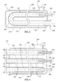
- FIG. 3 depicts a longitudinal cross-sectional view of a heat exchanger that includes a porous pipe having a bend therein according to an embodiment of the present invention.
- FIG. 4 depicts a longitudinal cross-sectional view of a heat exchanger that includes multiple porous members according to an embodiment of the present invention.
- FIG. 5 depicts a longitudinal cross-sectional view of a heat exchanger that includes a porous member having a stepped taper according to an embodiment of the present invention.
- FIG. 6 depicts a longitudinal cross-sectional view of a heat exchanger that includes a porous member having a substantially continuous taper according to an embodiment of the present invention.
- FIGS. 7A-7E depict transverse cross-sectional views of porous members according to embodiments of the present invention.
- FIG. 1 illustrates a partial cut-away view of a heat exchanger 110 according to an embodiment of the present invention. It is noted that, while operation of embodiments of the present invention is described in terms of the sublimation of carbon dioxide in the processing of natural gas, the present invention may be utilized for the sublimation, heating, cooling, and mixing of other fluids and for other processes, as will be appreciated and understood by those of ordinary skill in the art.
- fluid means any substance that may be caused to flow through a conduit and includes but is not limited to gases, two-phase gases, liquids, gels, plasmas, slurries, solid particles, and any combination thereof.
- the heat exchanger 110 may comprise a porous member 140 and a chamber 120 having an inlet 130 .
- the porous member 140 comprises a porous wall 150 that may extend along at least a portion of the length of the porous member 140 , an inlet 160 , and an outlet 170 .
- the porous wall 150 has a plurality of pores therethrough, and the plurality of pores may provide fluid communication between an interior of porous member 140 and the chamber 120 .
- the inlet 160 of porous member 140 comprises a first opening 180 in the porous member 140 and the outlet 170 thereof comprises a second opening 190 in the porous member 140 , each of the openings 180 and 190 , respectively, being substantially larger than each of the plurality of the pores in the porous wall 150 .
- the openings 180 and 190 may each be substantially larger in cross-sectional area than the cross-sectional area of each of the plurality of the pores in the porous wall 150 .
- an embodiment of the heat exchanger 110 may include an inlet and an outlet that each comprise a circular opening.
- the diameter of each of the first and second openings 180 and 190 may be at least 10,000 percent larger than a pore diameter of each of the plurality of pores.
- the inlet and outlet openings 180 and 190 may comprise any one of a variety of shapes having a similar size ratio of pore size to the first and second opening 180 and 190 size.
- the cross-sectional area of the first opening 180 may be smaller than the cross-sectional area of the second opening 190 .
- the porous member 140 may be formed from metal powder particles using conventional powder metallurgy techniques.
- the porous wall 150 may comprise a porous metal pipe 200 , such as is available from Mott Corporation, Farmington, Conn.
- a suitable metal for porous wall 150 is a 300-series stainless steel, such as 304L stainless steel or 316L stainless steel.
- the porous member 140 may be formed such that the pores are substantially uniform throughout the porous wall 150 .
- the term “pores” as used herein is the open volume within the porous wall 150 material matrix or network.
- the porous wall 150 may also have a substantially uniform interconnected porosity therethrough.
- the term “interconnected porosity” as used herein describes pores that are connected together and to the surfaces of the porous wall 150 to allow fluid to flow from one side of porous wall 150 to the other. In contrast, “isolated pores” do not have connectivity to both surfaces to allow fluid flow.
- the porous wall 150 of the porous member 140 may be tailored with a specific porosity, such that the permeability of the porous wall 150 may be tailored for a specific use. This may be accomplished by varying the pore shape, the pore size, the pore distribution, the thickness of porous wall 150 , and other characteristics of the porous wall 150 material. For example, the pore diameter may be varied from 0.01 to 500 micrometers.
- the term “pore diameter” as used herein is defined by the diameter of the largest hard spherical particle that may pass through the interconnected porosity.
- the chamber 120 may be formed within a casing 210 that surrounds the porous member 140 .
- the casing 210 may be generally cylindrical in shape and may be formed from a pipe 220 having closed ends 230 .
- the casing 210 may be formed from a stainless steel pipe 220 .
- the casing 210 may be sealingly coupled to an inlet fitting 240 to provide inlet 130 .
- the inlet fitting 240 may be arc welded or brazed to the casing 210 .
- the porous member 140 may be located substantially coaxial to the casing 210 . As shown in FIGS.
- the inner wall of the casing 210 and the outer wall of the porous member 140 may generally configure the chamber 120 in the form of an annulus.
- the chamber 120 may include an outlet fitting (not shown) that may be used for maintenance and cleaning of the heat exchanger 110 and that may be closed during the regular operation of the heat exchanger 110 .
- the porous wall 150 of the porous member 140 may be sealingly coupled with an inlet fitting 250 and an outlet fitting 260 .
- the inlet and outlet fittings 250 and 260 may also be sealingly coupled with the casing 210 , allowing the chamber 120 to be pressurized.
- the inlet fitting 250 and the outlet fitting 260 may be arc welded or brazed to the porous wall 150 and to the casing 210 .
- the porous member 140 may be generally formed with an axis that may define a centerline 270 through the porous member 140 .
- the porous member 140 may include one or more bends 280 with a curving centerline 270 .
- the heat exchanger 110 may incorporate a plurality of porous members 140 , each having a centerline 270 defined therethrough.
- the centerline 270 may pass through the center of each cross-sectional area, each cross-sectional area defined by the porous wall 150 within the porous member 140 at a reference plane that is perpendicular to the average flow direction therethrough.
- Forming the porous member 140 with one or more bends 280 and/or employing a plurality of porous members 140 may allow flexibility in the manufacture of the heat exchanger 110 .
- the flexibility in manufacture may facilitate flexibility in the size and shape of the heat exchanger 110 as well as flexibility in the locations of inlets 130 and 160 and the outlet 170 . This may facilitate the manufacture of the heat exchanger 110 to fit within a limited floor space and may allow for an efficient flow design for a processing plant incorporating heat exchanger 110 .
- the heat exchanger 110 may be configured with a porous member 140 that has a varying cross-sectional area, as shown in FIGS. 5 and 6 .
- the porous member 140 may comprise a porous pipe 200 that is tapered, having an internal cross-sectional area near the inlet 160 smaller than an internal cross-sectional area near the outlet 170 .
- the cross-sectional area may vary substantially continuously along a length of the porous pipe 200 , or may vary at steps along the length of the porous pipe 200 .
- An example of a step-tapered porous pipe 200 is shown in FIG. 5
- an example of a substantially continuously tapered porous pipe 200 is shown in FIG. 6 .
- the cross-sectional area of the porous member 140 may affect flow conditions within the porous member 140 . For example, as fluid enters the porous member 140 from chamber 120 through the porous wall 150 , the mass flow rate through the porous member 140 will increase along the length of the porous member 140 . If the cross-sectional area of the porous member 140 remains constant as the flow rate increases, the velocity of the flow will increase (assuming that there is little additional compression of the fluid). If it is desired to control the flow velocity within the porous member 140 , the cross-sectional area of the porous member 140 may be varied along its length to affect the flow velocity. For example, the cross-sectional area of the porous member 140 may be increased along its length such that the velocity of the flow may be relatively constant throughout the porous member 140 .
- the porous pipe 200 may have an annular cross-section as illustrated in FIG. 2B , or may have a cross-section of any variety of shapes.
- the cross-section of the porous pipe 200 may be, in transverse cross-section, of star-shaped, polygonal, elliptical, finned, or a combination thereof, as illustrated in FIGS. 7A-7E .
- the shape of the porous pipe 200 may be tailored for specific uses.
- the porous pipe 200 may be formed with a substantially uniform porous wall 150 thickness to facilitate uniform flow.
- the porous pipe 200 may also be formed in shapes such as a star (as shown in FIG. 7A ), an ellipse (as shown in FIG.
- the porous pipe 200 may be formed having a non-uniform porous wall 150 thickness to affect fluid flow through the porous wall 150 , to affect heat transfer through the porous wall 150 , to affect fluid flow within the porous member 140 , or a combination thereof.
- the porous wall 150 may have a complex shape using a combination of geometries such as fins 290 located outside the porous pipe 200 (as shown in FIG. 7D ), or inside the porous pipe 200 (as shown in FIG. 7E ).
- the heat exchanger 110 may be used to melt, vaporize, and/or sublime a solid particle suspended in a carrier fluid to convert the solid particle to a gaseous state.
- a solid particle suspended in a carrier fluid for example, solid carbon dioxide crystals suspended in natural gas may be sublimed within the porous member 140 .
- the heat exchanger 110 may be especially useful for such an application as it may operate to reduce or even prevent contact between sticky carbon dioxide crystals and the porous wall 150 of the porous member 140 , which may prevent fouling.
- the heat exchanger 110 may be operated by conveying a first fluid through the porous member 140 .
- the first fluid may be conveyed into the porous member 140 through the first inlet 160 to direct the flow approximately along the centerline 270 of the porous member 140 .
- a positive flow boundary layer may be formed along the inside of the porous wall 150 by conveying a second fluid into the porous member 140 through the porous wall 150 . This may prevent or reduce contact between the first fluid and the porous wall 150 of the porous member 140 . Both the first fluid and the second fluid may then be conveyed out of the porous member 140 through the outlet 170 .
- the heat exchanger 110 may be used to provide heat transfer between a first fluid and a second fluid.
- the first fluid may be conveyed at a first temperature through the first inlet 160 into the interior of the porous member 140
- the second fluid may be at a second temperature substantially different than the first temperature of the first fluid and conveyed through a second inlet 130 into the chamber 120 .
- the second fluid may be heated to the second temperature prior to being conveyed into the chamber 120 .
- the second fluid may then be conveyed from the chamber 120 into the interior of porous member 140 through the porous wall 150 .
- the first fluid and the second fluid may mix within the porous member 140 and heat may be transferred between the first fluid and the second fluid.
- the first fluid and the second fluid may then be conveyed out of the porous member 140 through the outlet 170 , both at a third temperature different than the first and the second temperatures.
- the present invention may be used as part of a liquefaction process for natural gas.
- the present invention may be used in conjunction with an apparatus for the liquefaction of natural gas and methods relating to the same, such as described in U.S. Pat. No. 6,962,061 to Wilding et al., the disclosure of which is incorporated herein in its entirety by reference.
- the methods of liquefaction of natural gas disclosed in the Wilding patent include cooling at least a portion of a mass of natural gas to form a slurry which comprises at least liquid natural gas and solid carbon dioxide.
- the slurry is flowed into a hydrocyclone and forms a thickened slush of solid carbon dioxide in liquid natural gas.
- the thickened slush is discharged from the hydrocyclone through an underflow while the remaining portion of the liquid natural gas is flowed through an overflow of the hydrocyclone.
- the first fluid comprises a continuous flow of a thickened slush or slurry including liquid natural gas and solid carbon dioxide as might be produced in a method according to the Wilding patent, as it is conveyed into the porous member 140 through an inlet 160 .
- the inlet 160 may direct the first fluid into the porous member 140 near the centerline 270 of the porous member 140 .
- a second fluid that comprises a continuous flow of heated gas, in this example (such as heated natural gas or heated methane), enters the interior of porous member 140 through the porous wall 150 .
- the flow of the second fluid through the porous wall 150 may be induced by a pressure gradient between the chamber 120 and the interior of the porous member 140 .
- the pressure inside of the porous member 140 may be about 1-100 psid less than the pressure of the chamber 120 . In one example, the pressure inside the porous member 140 may be about 25 psid less than the pressure of the chamber 120 .
- the second fluid may enter the porous member 140 uniformly through the porous wall 150 and create a positive flow boundary layer along the entire inside surface of the porous wall 150 of the porous member 140 .
- the first fluid entering the porous member 140 through the inlet 160 may be constrained from contacting the inside surface of the porous wall 150 of the porous member 140 by the flow of the second fluid entering the porous member 140 through the porous wall 150 .
- the substantially constant flow of the second fluid flowing through the porous wall 150 may facilitate the suspension of the solid carbon dioxide away from the porous wall 150 even as the first fluid is conveyed through a bend 280 in the porous member 140 .
- the positive flow boundary layer may not fully constrain the first fluid from contacting the porous wall 150 , but may only reduce the degree of contact between the first fluid and the porous wall 150 . If, for example, carbon dioxide crystals were to adhere to a portion of the porous wall 150 , the continuous flow of the heated first fluid through the porous wall 150 may heat the carbon dioxide crystals that adhere to the porous wall 150 .
- the heating of the carbon dioxide crystals will result in the melting or sublimation of the crystals, which may cause the crystals to release from the porous wall 150 or cause the carbon dioxide to fully transition to a gaseous form. This may reduce the amount of localized fouling that may occur within the heat exchanger 110 at a given time, and may allow the first fluid to continuously flow through the heat exchanger 110 during the operation thereof.
- the initial heat energy provided by the second fluid may be used to facilitate a phase change of the liquid methane of the first fluid to gaseous methane.
- the temperature of the first fluid may remain at about ⁇ 230° F. (this temperature may vary depending upon the pressure of the fluid) until all of the liquid methane of the first fluid is converted to gaseous methane.
- the solid carbon dioxide of the first fluid may now be suspended in the combined gaseous methane of the first and second fluids and may begin to sublime when the temperature of the combined fluids has reached about ⁇ 80° F. (this temperature may vary depending upon the pressure of the fluid environment).
- the solid carbon dioxide will be suspended in gaseous methane while the carbon dioxide changes phases from solid to vapor.
- the first fluid is conveyed through the porous member 140 , all of the carbon dioxide of the first fluid may be converted to gaseous carbon dioxide. After the carbon dioxide has been converted to gaseous form, the combined first and second fluid exits the porous member 140 through the outlet 170 .
- the first fluid may enter the porous member 140 through the inlet 160 at about 76 psia and about ⁇ 226° F. at a mass flow rate of about 660 lbm/hr.
- the second fluid may enter the chamber 120 at about 100 psia and about 157° F. at a mass flow rate of about 1520 lbm/hr, passing through the porous wall 150 of porous member 140 to the interior of porous member 140 .
- the combined first and second fluids may exit the porous member 140 through the outlet 170 at about ⁇ 70° F. and about 75 psia at a mass flow rate of about 2180 lbm/hr.
- the heat exchanger 110 may be designed for a wide variety of applications and in any number of sizes and configurations, as depicted in the various embodiments described herein.
- the porosity of the porous wall 150 of the porous member 140 may be determined by the surface area of the porous wall 150 and the desired flow rate through the pores at a given difference in pressure between the chamber 120 and the inside of the porous member 140 .
- the size of the porous member 140 may be determined by the mass flow rate and the amount of heat transfer needed to ensure the gas exiting porous member 140 is at the desired temperature.
- ⁇ P is the difference in pressure between the chamber 120 and the porous member 140
- K is the permeability coefficient of the porous wall 150 that varies with the porosity
- Q is the flux or mass flow rate through the porous wall 150
- ⁇ is the viscosity of the fluid that is passing through the porous wall 150
- X is the thickness of the porous wall 150 .
- a desirable diameter for the porous pipe 200 may be determined by the fluid flow rate as the first and second fluids are conveyed through and out of the porous member 140 .
- the configuration and orientation of the porous member 140 may affect the flow of the fluid through the porous member 140 , especially if the fluid contains solid particles, such as solid carbon dioxide.
- the particles may be drawn downward by gravity, and so it may be desirable to orient the porous member 140 such that the fluid flow through the porous member 140 is mostly horizontal.
- a horizontally oriented flow may cause solid particles to be conveyed within the porous member 140 at a velocity similar to the gases and/or liquids within which the solid particles are suspended.
- the apparatus and methods depicted and described herein enable the effective and efficient conveyance and sublimation of solid particles within a fluid.
- the invention may further be useful for a variety of applications other than the specific examples provided.
- the described apparatus and methods may be useful for the effective and efficient mixing, heating, cooling, and/or conveyance of fluids containing sticky, corrosive, and/or reactive chemicals.
Landscapes
- Engineering & Computer Science (AREA)
- Chemical & Material Sciences (AREA)
- Mechanical Engineering (AREA)
- General Engineering & Computer Science (AREA)
- Crystallography & Structural Chemistry (AREA)
- Chemical Kinetics & Catalysis (AREA)
- Heat-Exchange Devices With Radiators And Conduit Assemblies (AREA)
- Physical Or Chemical Processes And Apparatus (AREA)
Abstract
Description
ΔP=K·Q·μ·X
Claims (11)
Priority Applications (8)
| Application Number | Priority Date | Filing Date | Title |
|---|---|---|---|
| US11/855,071 US8061413B2 (en) | 2007-09-13 | 2007-09-13 | Heat exchangers comprising at least one porous member positioned within a casing |
| PCT/US2008/068938 WO2009035747A1 (en) | 2007-09-13 | 2008-07-01 | Heat exchanger and associated methods |
| MX2009013737A MX2009013737A (en) | 2007-09-13 | 2008-07-01 | Heat exchanger and associated methods. |
| CA 2690235 CA2690235C (en) | 2007-09-13 | 2008-07-01 | Heat exchanger and associated methods |
| US12/938,761 US9574713B2 (en) | 2007-09-13 | 2010-11-03 | Vaporization chambers and associated methods |
| US12/938,826 US9217603B2 (en) | 2007-09-13 | 2010-11-03 | Heat exchanger and related methods |
| US12/938,967 US9254448B2 (en) | 2007-09-13 | 2010-11-03 | Sublimation systems and associated methods |
| US13/284,737 US8544295B2 (en) | 2007-09-13 | 2011-10-28 | Methods of conveying fluids and methods of sublimating solid particles |
Applications Claiming Priority (1)
| Application Number | Priority Date | Filing Date | Title |
|---|---|---|---|
| US11/855,071 US8061413B2 (en) | 2007-09-13 | 2007-09-13 | Heat exchangers comprising at least one porous member positioned within a casing |
Related Child Applications (1)
| Application Number | Title | Priority Date | Filing Date |
|---|---|---|---|
| US13/284,737 Division US8544295B2 (en) | 2007-09-13 | 2011-10-28 | Methods of conveying fluids and methods of sublimating solid particles |
Publications (2)
| Publication Number | Publication Date |
|---|---|
| US20090071634A1 US20090071634A1 (en) | 2009-03-19 |
| US8061413B2 true US8061413B2 (en) | 2011-11-22 |
Family
ID=40452380
Family Applications (2)
| Application Number | Title | Priority Date | Filing Date |
|---|---|---|---|
| US11/855,071 Active 2028-11-13 US8061413B2 (en) | 2007-09-13 | 2007-09-13 | Heat exchangers comprising at least one porous member positioned within a casing |
| US13/284,737 Active US8544295B2 (en) | 2007-09-13 | 2011-10-28 | Methods of conveying fluids and methods of sublimating solid particles |
Family Applications After (1)
| Application Number | Title | Priority Date | Filing Date |
|---|---|---|---|
| US13/284,737 Active US8544295B2 (en) | 2007-09-13 | 2011-10-28 | Methods of conveying fluids and methods of sublimating solid particles |
Country Status (4)
| Country | Link |
|---|---|
| US (2) | US8061413B2 (en) |
| CA (1) | CA2690235C (en) |
| MX (1) | MX2009013737A (en) |
| WO (1) | WO2009035747A1 (en) |
Cited By (3)
| Publication number | Priority date | Publication date | Assignee | Title |
|---|---|---|---|---|
| US20110136068A1 (en) * | 2008-08-04 | 2011-06-09 | Andreas Lenk | Device for continuously preheating a mixture of burnable gas, more particularly natural gas and oxygen |
| US20180172326A1 (en) * | 2016-12-21 | 2018-06-21 | Hamilton Sundstrand Corporation | Porous media evaporator |
| US11911732B2 (en) | 2020-04-03 | 2024-02-27 | Nublu Innovations, Llc | Oilfield deep well processing and injection facility and methods |
Families Citing this family (10)
| Publication number | Priority date | Publication date | Assignee | Title |
|---|---|---|---|---|
| US9254448B2 (en) * | 2007-09-13 | 2016-02-09 | Battelle Energy Alliance, Llc | Sublimation systems and associated methods |
| US8555672B2 (en) | 2009-10-22 | 2013-10-15 | Battelle Energy Alliance, Llc | Complete liquefaction methods and apparatus |
| US8061413B2 (en) | 2007-09-13 | 2011-11-22 | Battelle Energy Alliance, Llc | Heat exchangers comprising at least one porous member positioned within a casing |
| US8899074B2 (en) | 2009-10-22 | 2014-12-02 | Battelle Energy Alliance, Llc | Methods of natural gas liquefaction and natural gas liquefaction plants utilizing multiple and varying gas streams |
| US9217603B2 (en) * | 2007-09-13 | 2015-12-22 | Battelle Energy Alliance, Llc | Heat exchanger and related methods |
| US9574713B2 (en) * | 2007-09-13 | 2017-02-21 | Battelle Energy Alliance, Llc | Vaporization chambers and associated methods |
| CN103017585B (en) | 2011-09-23 | 2015-01-28 | 北京兆阳光热技术有限公司 | Phase change heat exchange device |
| US10655911B2 (en) | 2012-06-20 | 2020-05-19 | Battelle Energy Alliance, Llc | Natural gas liquefaction employing independent refrigerant path |
| DE102014201908A1 (en) * | 2014-02-03 | 2015-08-06 | Duerr Cyplan Ltd. | Method for guiding a fluid flow, flow apparatus and its use |
| US11465093B2 (en) * | 2019-08-19 | 2022-10-11 | Exxonmobil Upstream Research Company | Compliant composite heat exchangers |
Citations (166)
| Publication number | Priority date | Publication date | Assignee | Title |
|---|---|---|---|---|
| US1222801A (en) | 1916-08-22 | 1917-04-17 | Rudolph R Rosenbaum | Apparatus for dephlegmation. |
| US2037679A (en) | 1935-01-24 | 1936-04-14 | Union Carbide & Carbon Corp | Method and apparatus for rejecting heat from a cascade system |
| US2037714A (en) | 1935-03-13 | 1936-04-21 | Union Carbide & Carbon Corp | Method and apparatus for operating cascade systems with regeneration |
| US2040059A (en) | 1935-03-01 | 1936-05-05 | Union Carbide & Carbon Corp | Method and apparatus for dispensing gas material |
| US2093805A (en) | 1935-03-13 | 1937-09-21 | Baufre William Lane De | Method of and apparatus for drying a moist gaseous mixture |
| US2157103A (en) | 1936-06-24 | 1939-05-09 | Linde Air Prod Co | Apparatus for and method of operating cascade systems |
| US2209534A (en) | 1937-10-06 | 1940-07-30 | Standard Oil Dev Co | Method for producing gas wells |
| US2494120A (en) | 1947-09-23 | 1950-01-10 | Phillips Petroleum Co | Expansion refrigeration system and method |
| US2900797A (en) | 1956-05-25 | 1959-08-25 | Kurata Fred | Separation of normally gaseous acidic components and methane |
| US2937503A (en) | 1955-09-19 | 1960-05-24 | Nat Tank Co | Turbo-expander-compressor units |
| US3132016A (en) | 1960-03-09 | 1964-05-05 | Univ Kansas State | Process for the separation of fluid components from mixtures thereof |
| US3168136A (en) | 1955-03-17 | 1965-02-02 | Babcock & Wilcox Co | Shell and tube-type heat exchanger |
| US3182461A (en) | 1961-09-19 | 1965-05-11 | Hydrocarbon Research Inc | Natural gas liquefaction and separation |
| US3193468A (en) | 1960-07-12 | 1965-07-06 | Babcock & Wilcox Co | Boiling coolant nuclear reactor system |
| US3213631A (en) | 1961-09-22 | 1965-10-26 | Lummus Co | Separated from a gas mixture on a refrigeration medium |
| US3218816A (en) | 1961-06-01 | 1965-11-23 | Air Liquide | Process for cooling a gas mixture to a low temperature |
| US3236057A (en) | 1962-05-28 | 1966-02-22 | Conch Int Methane Ltd | Removal of carbon dioxide and/or hydrogen sulphide from methane |
| US3254496A (en) | 1962-04-05 | 1966-06-07 | Transp Et De La Valorisation D | Natural gas liquefaction process |
| US3289756A (en) * | 1964-10-15 | 1966-12-06 | Olin Mathieson | Heat exchanger |
| US3292380A (en) | 1964-04-28 | 1966-12-20 | Coastal States Gas Producing C | Method and equipment for treating hydrocarbon gases for pressure reduction and condensate recovery |
| US3312073A (en) | 1964-01-23 | 1967-04-04 | Conch Int Methane Ltd | Process for liquefying natural gas |
| US3315475A (en) | 1963-09-26 | 1967-04-25 | Conch Int Methane Ltd | Freezing out contaminant methane in the recovery of hydrogen from industrial gases |
| US3323315A (en) | 1964-07-15 | 1967-06-06 | Conch Int Methane Ltd | Gas liquefaction employing an evaporating and gas expansion refrigerant cycles |
| US3326453A (en) | 1965-10-23 | 1967-06-20 | Union Carbide Corp | Gas-bearing assembly |
| US3349020A (en) | 1964-01-08 | 1967-10-24 | Conch Int Methane Ltd | Low temperature electrophoretic liquified gas separation |
| US3362173A (en) | 1965-02-16 | 1968-01-09 | Lummus Co | Liquefaction process employing cascade refrigeration |
| US3376709A (en) | 1965-07-14 | 1968-04-09 | Frank H. Dickey | Separation of acid gases from natural gas by solidification |
| US3407052A (en) | 1966-08-17 | 1968-10-22 | Conch Int Methane Ltd | Natural gas liquefaction with controlled b.t.u. content |
| US3406496A (en) | 1965-09-06 | 1968-10-22 | Int Nickel Co | Separation of hydrogen from other gases |
| US3416324A (en) | 1967-06-12 | 1968-12-17 | Judson S. Swearingen | Liquefaction of a gaseous mixture employing work expanded gaseous mixture as refrigerant |
| US3422887A (en) | 1967-06-19 | 1969-01-21 | Graham Mfg Co Inc | Condenser for distillation column |
| US3448587A (en) | 1966-07-11 | 1969-06-10 | Phillips Petroleum Co | Concentration of high gas content liquids |
| US3487652A (en) | 1966-08-22 | 1970-01-06 | Phillips Petroleum Co | Crystal separation and purification |
| US3503220A (en) | 1967-07-27 | 1970-03-31 | Chicago Bridge & Iron Co | Expander cycle for natural gas liquefication with split feed stream |
| US3516262A (en) | 1967-05-01 | 1970-06-23 | Mc Donnell Douglas Corp | Separation of gas mixtures such as methane and nitrogen mixtures |
| US3548606A (en) | 1968-07-08 | 1970-12-22 | Phillips Petroleum Co | Serial incremental refrigerant expansion for gas liquefaction |
| US3596473A (en) | 1967-12-27 | 1971-08-03 | Messer Griesheim Gmbh | Liquefaction process for gas mixtures by means of fractional condensation |
| US3608323A (en) | 1967-01-31 | 1971-09-28 | Liquid Air Canada | Natural gas liquefaction process |
| US3616652A (en) | 1966-09-27 | 1971-11-02 | Conch Int Methane Ltd | Process and apparatus for liquefying natural gas containing nitrogen by using cooled expanded and flashed gas therefrom as a coolant therefor |
| US3628340A (en) | 1969-11-13 | 1971-12-21 | Hydrocarbon Research Inc | Process for cryogenic purification of hydrogen |
| US3677019A (en) | 1969-08-01 | 1972-07-18 | Union Carbide Corp | Gas liquefaction process and apparatus |
| US3690114A (en) | 1969-11-17 | 1972-09-12 | Judson S Swearingen | Refrigeration process for use in liquefication of gases |
| US3724226A (en) | 1971-04-20 | 1973-04-03 | Gulf Research Development Co | Lng expander cycle process employing integrated cryogenic purification |
| US3724225A (en) | 1970-02-25 | 1973-04-03 | Exxon Research Engineering Co | Separation of carbon dioxide from a natural gas stream |
| US3735600A (en) | 1970-05-11 | 1973-05-29 | Gulf Research Development Co | Apparatus and process for liquefaction of natural gases |
| US3846993A (en) | 1971-02-01 | 1974-11-12 | Phillips Petroleum Co | Cryogenic extraction process for natural gas liquids |
| US3886885A (en) | 1972-07-31 | 1975-06-03 | Linde Ag | Container system for the storage and/or transportation of liquefied gas |
| US3897226A (en) | 1972-04-19 | 1975-07-29 | Petrocarbon Dev Ltd | Controlling the concentration of impurities in a gas stream |
| US4001116A (en) | 1975-03-05 | 1977-01-04 | Chicago Bridge & Iron Company | Gravitational separation of solids from liquefied natural gas |
| US4004430A (en) | 1974-09-30 | 1977-01-25 | The Lummus Company | Process and apparatus for treating natural gas |
| US4007601A (en) | 1975-10-16 | 1977-02-15 | The United States Of America As Represented By The Administrator Of The National Aeronautics And Space Administration | Tubular sublimator/evaporator heat sink |
| US4022597A (en) | 1976-04-23 | 1977-05-10 | Gulf Oil Corporation | Separation of liquid hydrocarbons from natural gas |
| US4025315A (en) | 1971-05-19 | 1977-05-24 | San Diego Gas & Electric Co. | Method of odorizing liquid natural gas |
| US4032337A (en) | 1976-07-27 | 1977-06-28 | Crucible Inc. | Method and apparatus for pressurizing hot-isostatic pressure vessels |
| US4120911A (en) | 1971-07-02 | 1978-10-17 | Chevron Research Company | Method for concentrating a slurry containing a solid particulate component |
| US4128410A (en) | 1974-02-25 | 1978-12-05 | Gulf Oil Corporation | Natural gas treatment |
| US4183369A (en) | 1977-11-04 | 1980-01-15 | Thomas Robert E | Method of transmitting hydrogen |
| US4187689A (en) | 1978-09-13 | 1980-02-12 | Chicago Bridge & Iron Company | Apparatus for reliquefying boil-off natural gas from a storage tank |
| US4294274A (en) | 1978-07-17 | 1981-10-13 | Noranda Mines Limited | Hydrogen injection into gas pipelines and other pressurized containers |
| US4318723A (en) | 1979-11-14 | 1982-03-09 | Koch Process Systems, Inc. | Cryogenic distillative separation of acid gases from methane |
| US4334902A (en) | 1979-12-12 | 1982-06-15 | Compagnie Francaise D'etudes Et De Construction "Technip" | Method of and system for refrigerating a fluid to be cooled down to a low temperature |
| US4359871A (en) | 1978-12-01 | 1982-11-23 | Linde Aktiengesellschaft | Method of and apparatus for the cooling of natural gas |
| US4370150A (en) | 1980-08-21 | 1983-01-25 | Phillips Petroleum Company | Engine performance operating on field gas as engine fuel |
| US4453956A (en) | 1981-07-07 | 1984-06-12 | Snamprogetti S.P.A. | Recovering condensables from natural gas |
| US4479536A (en) | 1980-08-26 | 1984-10-30 | Bronswerk K.A.B. B.V. | Heat exchanger for a gaseous and a liquid medium |
| US4479533A (en) | 1980-05-27 | 1984-10-30 | Ingemar Persson | Tertiary heat exchanger |
| US4522636A (en) | 1984-02-08 | 1985-06-11 | Kryos Energy Inc. | Pipeline gas pressure reduction with refrigeration generation |
| US4561496A (en) | 1983-01-25 | 1985-12-31 | Borsig Gmbh | Heat exchanger for the cooling of gases, particularly from the synthesis of ammonia |
| US4609390A (en) | 1984-05-14 | 1986-09-02 | Wilson Richard A | Process and apparatus for separating hydrocarbon gas into a residue gas fraction and a product fraction |
| US4611655A (en) | 1983-01-05 | 1986-09-16 | Power Shaft Engine, Limited Partnership | Heat exchanger |
| US4654522A (en) | 1983-09-22 | 1987-03-31 | Cts Corporation | Miniature position encoder with radially non-aligned light emitters and detectors |
| US4798242A (en) | 1985-05-30 | 1989-01-17 | Aisin Seiki Kabushiki Kaisha Co., Ltd. | Heat exchanger for recovering heat from exhaust gases |
| US4822393A (en) | 1988-06-30 | 1989-04-18 | Kryos Energy Inc. | Natural gas pretreatment prior to liquefaction |
| US4846862A (en) | 1988-09-06 | 1989-07-11 | Air Products And Chemicals, Inc. | Reliquefaction of boil-off from liquefied natural gas |
| US4869313A (en) | 1988-07-15 | 1989-09-26 | General Electric Company | Low pressure drop condenser/evaporator pump heat exchanger |
| US4970867A (en) | 1989-08-21 | 1990-11-20 | Air Products And Chemicals, Inc. | Liquefaction of natural gas using process-loaded expanders |
| US4993485A (en) | 1989-09-18 | 1991-02-19 | Gorman Jeremy W | Easily disassembled heat exchanger of high efficiency |
| US5003782A (en) | 1990-07-06 | 1991-04-02 | Zoran Kucerija | Gas expander based power plant system |
| US5032143A (en) | 1987-05-08 | 1991-07-16 | A. Ahlstrom Corporation | Method and apparatus for treating process gases |
| US5036671A (en) | 1990-02-06 | 1991-08-06 | Liquid Air Engineering Company | Method of liquefying natural gas |
| US5062270A (en) | 1990-08-31 | 1991-11-05 | Exxon Production Research Company | Method and apparatus to start-up controlled freezing zone process and purify the product stream |
| US5174796A (en) | 1991-10-09 | 1992-12-29 | Uop | Process for the purification of natural gas |
| US5218832A (en) | 1991-09-16 | 1993-06-15 | Ball Corporation | Separation method and apparatus for a liquid and gas mixture |
| US5291736A (en) | 1991-09-30 | 1994-03-08 | Compagnie Francaise D'etudes Et De Construction "Technip" | Method of liquefaction of natural gas |
| US5327730A (en) | 1993-05-12 | 1994-07-12 | American Gas & Technology, Inc. | Method and apparatus for liquifying natural gas for fuel for vehicles and fuel tank for use therewith |
| US5375422A (en) | 1991-04-09 | 1994-12-27 | Butts; Rayburn C. | High efficiency nitrogen rejection unit |
| US5379832A (en) | 1992-02-18 | 1995-01-10 | Aqua Systems, Inc. | Shell and coil heat exchanger |
| US5390499A (en) | 1993-10-27 | 1995-02-21 | Liquid Carbonic Corporation | Process to increase natural gas methane content |
| US5419392A (en) | 1993-02-10 | 1995-05-30 | Maruyama; Noboru | Heat exchanging apparatus |
| US5450728A (en) | 1993-11-30 | 1995-09-19 | Air Products And Chemicals, Inc. | Recovery of volatile organic compounds from gas streams |
| EP0676599A1 (en) | 1992-07-10 | 1995-10-11 | Aktsionernoe Obshestvo " SIGMA-GAZ" | Method of gas cooling and a gas cooler |
| US5473900A (en) | 1994-04-29 | 1995-12-12 | Phillips Petroleum Company | Method and apparatus for liquefaction of natural gas |
| US5489725A (en) | 1992-11-06 | 1996-02-06 | Institut Francais Du Petrole | Process and device for catalytic dehydrogenation of a C2+ paraffinic charge comprising means for inhibiting the freezing of water in the effluent |
| US5505232A (en) | 1993-10-20 | 1996-04-09 | Cryofuel Systems, Inc. | Integrated refueling system for vehicles |
| US5505048A (en) | 1993-05-05 | 1996-04-09 | Ha; Bao | Method and apparatus for the separation of C4 hydrocarbons from gaseous mixtures containing the same |
| US5511382A (en) | 1993-10-26 | 1996-04-30 | L'air Liquide, Societe Anonyme Pour L'etude Et L'exploitation Des Procedes Georges Claude | Process and installation for the cryogenic purification of hydrogen |
| US5537827A (en) | 1995-06-07 | 1996-07-23 | Low; William R. | Method for liquefaction of natural gas |
| US5551256A (en) | 1994-11-11 | 1996-09-03 | Linde Aktiengesellschaft | Process for liquefaction of natural gas |
| US5600969A (en) | 1995-12-18 | 1997-02-11 | Phillips Petroleum Company | Process and apparatus to produce a small scale LNG stream from an existing NGL expander plant demethanizer |
| US5615738A (en) | 1994-06-29 | 1997-04-01 | Cecebe Technologies Inc. | Internal bypass valve for a heat exchanger |
| US5615561A (en) | 1994-11-08 | 1997-04-01 | Williams Field Services Company | LNG production in cryogenic natural gas processing plants |
| US5655388A (en) | 1995-07-27 | 1997-08-12 | Praxair Technology, Inc. | Cryogenic rectification system for producing high pressure gaseous oxygen and liquid product |
| US5669234A (en) | 1996-07-16 | 1997-09-23 | Phillips Petroleum Company | Efficiency improvement of open-cycle cascaded refrigeration process |
| US5718126A (en) | 1995-10-11 | 1998-02-17 | Institut Francais Du Petrole | Process and device for liquefying and for processing a natural gas |
| US5755114A (en) | 1997-01-06 | 1998-05-26 | Abb Randall Corporation | Use of a turboexpander cycle in liquefied natural gas process |
| US5755280A (en) | 1995-05-04 | 1998-05-26 | Packinox | Plate-type heat exchanger |
| US5799505A (en) | 1997-07-28 | 1998-09-01 | Praxair Technology, Inc. | System for producing cryogenic liquefied industrial gas |
| US5819555A (en) | 1995-09-08 | 1998-10-13 | Engdahl; Gerald | Removal of carbon dioxide from a feed stream by carbon dioxide solids separation |
| US5836173A (en) | 1997-05-01 | 1998-11-17 | Praxair Technology, Inc. | System for producing cryogenic liquid |
| US5916260A (en) | 1995-10-05 | 1999-06-29 | Bhp Petroleum Pty Ltd. | Liquefaction process |
| JPH11200817A (en) | 1998-01-05 | 1999-07-27 | Central Res Inst Of Electric Power Ind | Hydrogen separation type thermal power generation system |
| US5950453A (en) | 1997-06-20 | 1999-09-14 | Exxon Production Research Company | Multi-component refrigeration process for liquefaction of natural gas |
| US5956971A (en) | 1997-07-01 | 1999-09-28 | Exxon Production Research Company | Process for liquefying a natural gas stream containing at least one freezable component |
| US5983665A (en) | 1998-03-03 | 1999-11-16 | Air Products And Chemicals, Inc. | Production of refrigerated liquid methane |
| US6023944A (en) | 1996-08-30 | 2000-02-15 | British Nuclear Fuels, Plc | Apparatus and method for processing a sublimed material |
| US6041620A (en) | 1998-12-30 | 2000-03-28 | Praxair Technology, Inc. | Cryogenic industrial gas liquefaction with hybrid refrigeration generation |
| US6085547A (en) | 1998-09-18 | 2000-07-11 | Johnston; Richard P. | Simple method and apparatus for the partial conversion of natural gas to liquid natural gas |
| US6085546A (en) | 1998-09-18 | 2000-07-11 | Johnston; Richard P. | Method and apparatus for the partial conversion of natural gas to liquid natural gas |
| US6105390A (en) | 1997-12-16 | 2000-08-22 | Bechtel Bwxt Idaho, Llc | Apparatus and process for the refrigeration, liquefaction and separation of gases with varying levels of purity |
| US6131395A (en) | 1999-03-24 | 2000-10-17 | Lockheed Martin Corporation | Propellant densification apparatus and method |
| US6131407A (en) | 1999-03-04 | 2000-10-17 | Wissolik; Robert | Natural gas letdown liquefaction system |
| US6138746A (en) | 1999-02-24 | 2000-10-31 | Baltimore Aircoil Company, Inc. | Cooling coil for a thermal storage tower |
| US6138473A (en) | 1998-03-02 | 2000-10-31 | L'air Liquide, Societe Anonyme Pour I'etude Et I'exploitation Des Procedes Georges Claude | Station and process for dispensing a reduced-pressure gas |
| US6196021B1 (en) | 1999-03-23 | 2001-03-06 | Robert Wissolik | Industrial gas pipeline letdown liquefaction system |
| US6200536B1 (en) * | 1997-06-26 | 2001-03-13 | Battelle Memorial Institute | Active microchannel heat exchanger |
| US6212891B1 (en) | 1997-12-19 | 2001-04-10 | Exxonmobil Upstream Research Company | Process components, containers, and pipes suitable for containing and transporting cryogenic temperature fluids |
| US6220053B1 (en) | 2000-01-10 | 2001-04-24 | Praxair Technology, Inc. | Cryogenic industrial gas liquefaction system |
| US6220052B1 (en) | 1999-08-17 | 2001-04-24 | Liberty Fuels, Inc. | Apparatus and method for liquefying natural gas for vehicular use |
| US6301927B1 (en) | 1998-01-08 | 2001-10-16 | Satish Reddy | Autorefrigeration separation of carbon dioxide |
| US6354105B1 (en) | 1999-12-03 | 2002-03-12 | Ipsi L.L.C. | Split feed compression process for high recovery of ethane and heavier components |
| JP2002071861A (en) | 2000-09-01 | 2002-03-12 | Kawasaki Heavy Ind Ltd | Combination type heat exchanger |
| US6367286B1 (en) | 2000-11-01 | 2002-04-09 | Black & Veatch Pritchard, Inc. | System and process for liquefying high pressure natural gas |
| US6372019B1 (en) | 1998-10-16 | 2002-04-16 | Translang Technologies, Ltd. | Method of and apparatus for the separation of components of gas mixtures and liquefaction of a gas |
| US6370910B1 (en) | 1998-05-21 | 2002-04-16 | Shell Oil Company | Liquefying a stream enriched in methane |
| US6375906B1 (en) | 1999-08-12 | 2002-04-23 | Idatech, Llc | Steam reforming method and apparatus incorporating a hydrocarbon feedstock |
| US6378330B1 (en) | 1999-12-17 | 2002-04-30 | Exxonmobil Upstream Research Company | Process for making pressurized liquefied natural gas from pressured natural gas using expansion cooling |
| US6382310B1 (en) | 2000-08-15 | 2002-05-07 | American Standard International Inc. | Stepped heat exchanger coils |
| EP1205721A1 (en) | 2000-11-02 | 2002-05-15 | Air Products And Chemicals, Inc. | A process and apparatus for the production of a liquid cryogen |
| US6390114B1 (en) | 1999-11-08 | 2002-05-21 | Shell Oil Company | Method and apparatus for suppressing and controlling slugflow in a multi-phase fluid stream |
| US6389844B1 (en) | 1998-11-18 | 2002-05-21 | Shell Oil Company | Plant for liquefying natural gas |
| US6397936B1 (en) * | 1999-05-14 | 2002-06-04 | Creare Inc. | Freeze-tolerant condenser for a closed-loop heat-transfer system |
| US6400896B1 (en) | 1999-07-02 | 2002-06-04 | Trexco, Llc | Phase change material heat exchanger with heat energy transfer elements extending through the phase change material |
| US6410087B1 (en) | 1999-11-01 | 2002-06-25 | Medical Carbon Research Institute, Llc | Deposition of pyrocarbon |
| US6412302B1 (en) | 2001-03-06 | 2002-07-02 | Abb Lummus Global, Inc. - Randall Division | LNG production using dual independent expander refrigeration cycles |
| US6427464B1 (en) | 1999-01-15 | 2002-08-06 | York International Corporation | Hot gas bypass control for centrifugal chillers |
| US6442969B1 (en) | 2000-05-02 | 2002-09-03 | Institut Francais Du Petrole | Process and device for separation of at least one acid gas that is contained in a gas mixture |
| US6581510B2 (en) | 2001-06-12 | 2003-06-24 | Klockner Hansel Processing Gmbh | Cooking apparatus |
| US6581409B2 (en) | 2001-05-04 | 2003-06-24 | Bechtel Bwxt Idaho, Llc | Apparatus for the liquefaction of natural gas and methods related to same |
| US6694774B1 (en) | 2003-02-04 | 2004-02-24 | Praxair Technology, Inc. | Gas liquefaction method using natural gas and mixed gas refrigeration |
| US20040083888A1 (en) | 2002-11-01 | 2004-05-06 | Qualls Wesley R. | Heat integration system for natural gas liquefaction |
| US6742358B2 (en) | 2001-06-08 | 2004-06-01 | Elkcorp | Natural gas liquefaction |
| US20040105812A1 (en) | 1999-08-17 | 2004-06-03 | Tonkovich Anna Lee Y. | Chemical reactor and method for gas phase reactant catalytic reactions |
| US6767388B2 (en) | 2001-03-29 | 2004-07-27 | Institut Francais Du Petrole | Process for dehydrating and fractionating a low-pressure natural gas |
| US20040177646A1 (en) | 2003-03-07 | 2004-09-16 | Elkcorp | LNG production in cryogenic natural gas processing plants |
| US20050183452A1 (en) | 2004-02-24 | 2005-08-25 | Hahn Paul R. | LNG system with warm nitrogen rejection |
| US20050220704A1 (en) | 2004-03-30 | 2005-10-06 | Morrow Jeffrey M | Method of storing and supplying hydrogen to a pipeline |
| US20050279132A1 (en) | 2004-06-16 | 2005-12-22 | Eaton Anthony P | LNG system with enhanced turboexpander configuration |
| US20070017250A1 (en) | 2001-05-04 | 2007-01-25 | Battelle Energy Alliance, Llc | Apparatus for the liquefaction of a gas and methods relating to same |
| US20070107465A1 (en) | 2001-05-04 | 2007-05-17 | Battelle Energy Alliance, Llc | Apparatus for the liquefaction of gas and methods relating to same |
| US20070137246A1 (en) | 2001-05-04 | 2007-06-21 | Battelle Energy Alliance, Llc | Systems and methods for delivering hydrogen and separation of hydrogen from a carrier medium |
| US20070193303A1 (en) | 2004-06-18 | 2007-08-23 | Exxonmobil Upstream Research Company | Scalable capacity liquefied natural gas plant |
| US7575624B2 (en) | 2006-12-19 | 2009-08-18 | Uop Pllc | Molecular sieve and membrane system to purify natural gas |
| US7591150B2 (en) | 2001-05-04 | 2009-09-22 | Battelle Energy Alliance, Llc | Apparatus for the liquefaction of natural gas and methods relating to same |
| US7594414B2 (en) | 2001-05-04 | 2009-09-29 | Battelle Energy Alliance, Llc | Apparatus for the liquefaction of natural gas and methods relating to same |
| US20100088920A1 (en) | 2008-10-10 | 2010-04-15 | Larou Albert M | Harvest drying method and apparatus |
| US7765920B2 (en) | 2002-03-04 | 2010-08-03 | Relco Unisystems Corporation | Air-lift dryer for processing high-lactose aqueous fluids |
Family Cites Families (28)
| Publication number | Priority date | Publication date | Assignee | Title |
|---|---|---|---|---|
| US2701641A (en) | 1952-11-26 | 1955-02-08 | Stamicarbon | Method for cleaning coal |
| GB772303A (en) | 1954-09-20 | 1957-04-10 | Smidth & Co As F L | Improvements in the separation of slurries into fractions of differing particle content |
| GB1527794A (en) | 1976-01-28 | 1978-10-11 | Nat Res Dev | Cyclone separator |
| DE2624189A1 (en) * | 1976-05-29 | 1977-12-08 | Daimler Benz Ag | AIR COMPRESSING INJECTION COMBUSTION ENGINE WITH ADDITIONAL CHAMBER |
| CS229768B1 (en) | 1982-07-23 | 1984-06-18 | Jaroslav Ing Csc Vitovec | Device for continuous vapour desublimation of subliming substance |
| NL8700698A (en) | 1987-03-25 | 1988-10-17 | Bb Romico B V I O | ROTARY PARTICLE SEPARATOR. |
| US4783272A (en) | 1987-08-28 | 1988-11-08 | Atlantic Richfield Company | Removing solids from process separator vessels |
| US5252613A (en) | 1992-12-18 | 1993-10-12 | Exxon Research & Engineering Company | Enhanced catalyst mixing in slurry bubble columns (OP-3723) |
| US5325673A (en) * | 1993-02-23 | 1994-07-05 | The M. W. Kellogg Company | Natural gas liquefaction pretreatment process |
| NL1000109C2 (en) | 1995-04-11 | 1996-04-16 | Hoek Mach Zuurstoff | A method of condensing a volatile substance from a gas stream and apparatus therefor. |
| US7219512B1 (en) | 2001-05-04 | 2007-05-22 | Battelle Energy Alliance, Llc | Apparatus for the liquefaction of natural gas and methods relating to same |
| NZ534723A (en) | 2002-01-18 | 2004-10-29 | Univ Curtin Tech | Process and device for production of LNG by removal of freezable solids |
| US6997012B2 (en) | 2004-01-06 | 2006-02-14 | Battelle Energy Alliance, Llc | Method of Liquifying a gas |
| GB2416389B (en) | 2004-07-16 | 2007-01-10 | Statoil Asa | LCD liquefaction process |
| US7673476B2 (en) | 2005-03-28 | 2010-03-09 | Cambridge Cryogenics Technologies | Compact, modular method and apparatus for liquefying natural gas |
| US8250883B2 (en) | 2006-12-26 | 2012-08-28 | Repsol Ypf, S.A. | Process to obtain liquefied natural gas |
| US20100018248A1 (en) | 2007-01-19 | 2010-01-28 | Eleanor R Fieler | Controlled Freeze Zone Tower |
| US9003828B2 (en) | 2007-07-09 | 2015-04-14 | Lng Technology Pty Ltd | Method and system for production of liquid natural gas |
| US8555672B2 (en) | 2009-10-22 | 2013-10-15 | Battelle Energy Alliance, Llc | Complete liquefaction methods and apparatus |
| US9574713B2 (en) | 2007-09-13 | 2017-02-21 | Battelle Energy Alliance, Llc | Vaporization chambers and associated methods |
| US8061413B2 (en) | 2007-09-13 | 2011-11-22 | Battelle Energy Alliance, Llc | Heat exchangers comprising at least one porous member positioned within a casing |
| US8899074B2 (en) | 2009-10-22 | 2014-12-02 | Battelle Energy Alliance, Llc | Methods of natural gas liquefaction and natural gas liquefaction plants utilizing multiple and varying gas streams |
| US9217603B2 (en) | 2007-09-13 | 2015-12-22 | Battelle Energy Alliance, Llc | Heat exchanger and related methods |
| US9254448B2 (en) | 2007-09-13 | 2016-02-09 | Battelle Energy Alliance, Llc | Sublimation systems and associated methods |
| RU2520269C2 (en) | 2008-08-29 | 2014-06-20 | Шелл Интернэшнл Рисерч Маатсхаппий Б.В. | Removal of gaseous contaminants from gas flow containing gaseous contaminants and device to this end |
| US8627681B2 (en) | 2009-03-04 | 2014-01-14 | Lummus Technology Inc. | Nitrogen removal with iso-pressure open refrigeration natural gas liquids recovery |
| US8245727B2 (en) | 2009-06-26 | 2012-08-21 | Pamela Mooney, legal representative | Flow control valve and method of use |
| US20110094261A1 (en) | 2009-10-22 | 2011-04-28 | Battelle Energy Alliance, Llc | Natural gas liquefaction core modules, plants including same and related methods |
-
2007
- 2007-09-13 US US11/855,071 patent/US8061413B2/en active Active
-
2008
- 2008-07-01 CA CA 2690235 patent/CA2690235C/en not_active Expired - Fee Related
- 2008-07-01 WO PCT/US2008/068938 patent/WO2009035747A1/en active Application Filing
- 2008-07-01 MX MX2009013737A patent/MX2009013737A/en active IP Right Grant
-
2011
- 2011-10-28 US US13/284,737 patent/US8544295B2/en active Active
Patent Citations (172)
| Publication number | Priority date | Publication date | Assignee | Title |
|---|---|---|---|---|
| US1222801A (en) | 1916-08-22 | 1917-04-17 | Rudolph R Rosenbaum | Apparatus for dephlegmation. |
| US2037679A (en) | 1935-01-24 | 1936-04-14 | Union Carbide & Carbon Corp | Method and apparatus for rejecting heat from a cascade system |
| US2040059A (en) | 1935-03-01 | 1936-05-05 | Union Carbide & Carbon Corp | Method and apparatus for dispensing gas material |
| US2037714A (en) | 1935-03-13 | 1936-04-21 | Union Carbide & Carbon Corp | Method and apparatus for operating cascade systems with regeneration |
| US2093805A (en) | 1935-03-13 | 1937-09-21 | Baufre William Lane De | Method of and apparatus for drying a moist gaseous mixture |
| US2157103A (en) | 1936-06-24 | 1939-05-09 | Linde Air Prod Co | Apparatus for and method of operating cascade systems |
| US2209534A (en) | 1937-10-06 | 1940-07-30 | Standard Oil Dev Co | Method for producing gas wells |
| US2494120A (en) | 1947-09-23 | 1950-01-10 | Phillips Petroleum Co | Expansion refrigeration system and method |
| US3168136A (en) | 1955-03-17 | 1965-02-02 | Babcock & Wilcox Co | Shell and tube-type heat exchanger |
| US2937503A (en) | 1955-09-19 | 1960-05-24 | Nat Tank Co | Turbo-expander-compressor units |
| US2900797A (en) | 1956-05-25 | 1959-08-25 | Kurata Fred | Separation of normally gaseous acidic components and methane |
| US3132016A (en) | 1960-03-09 | 1964-05-05 | Univ Kansas State | Process for the separation of fluid components from mixtures thereof |
| US3193468A (en) | 1960-07-12 | 1965-07-06 | Babcock & Wilcox Co | Boiling coolant nuclear reactor system |
| US3218816A (en) | 1961-06-01 | 1965-11-23 | Air Liquide | Process for cooling a gas mixture to a low temperature |
| US3182461A (en) | 1961-09-19 | 1965-05-11 | Hydrocarbon Research Inc | Natural gas liquefaction and separation |
| US3213631A (en) | 1961-09-22 | 1965-10-26 | Lummus Co | Separated from a gas mixture on a refrigeration medium |
| US3254496A (en) | 1962-04-05 | 1966-06-07 | Transp Et De La Valorisation D | Natural gas liquefaction process |
| US3236057A (en) | 1962-05-28 | 1966-02-22 | Conch Int Methane Ltd | Removal of carbon dioxide and/or hydrogen sulphide from methane |
| US3315475A (en) | 1963-09-26 | 1967-04-25 | Conch Int Methane Ltd | Freezing out contaminant methane in the recovery of hydrogen from industrial gases |
| US3349020A (en) | 1964-01-08 | 1967-10-24 | Conch Int Methane Ltd | Low temperature electrophoretic liquified gas separation |
| US3312073A (en) | 1964-01-23 | 1967-04-04 | Conch Int Methane Ltd | Process for liquefying natural gas |
| US3292380A (en) | 1964-04-28 | 1966-12-20 | Coastal States Gas Producing C | Method and equipment for treating hydrocarbon gases for pressure reduction and condensate recovery |
| US3323315A (en) | 1964-07-15 | 1967-06-06 | Conch Int Methane Ltd | Gas liquefaction employing an evaporating and gas expansion refrigerant cycles |
| US3289756A (en) * | 1964-10-15 | 1966-12-06 | Olin Mathieson | Heat exchanger |
| US3362173A (en) | 1965-02-16 | 1968-01-09 | Lummus Co | Liquefaction process employing cascade refrigeration |
| US3376709A (en) | 1965-07-14 | 1968-04-09 | Frank H. Dickey | Separation of acid gases from natural gas by solidification |
| US3406496A (en) | 1965-09-06 | 1968-10-22 | Int Nickel Co | Separation of hydrogen from other gases |
| US3326453A (en) | 1965-10-23 | 1967-06-20 | Union Carbide Corp | Gas-bearing assembly |
| US3448587A (en) | 1966-07-11 | 1969-06-10 | Phillips Petroleum Co | Concentration of high gas content liquids |
| US3407052A (en) | 1966-08-17 | 1968-10-22 | Conch Int Methane Ltd | Natural gas liquefaction with controlled b.t.u. content |
| US3487652A (en) | 1966-08-22 | 1970-01-06 | Phillips Petroleum Co | Crystal separation and purification |
| US3616652A (en) | 1966-09-27 | 1971-11-02 | Conch Int Methane Ltd | Process and apparatus for liquefying natural gas containing nitrogen by using cooled expanded and flashed gas therefrom as a coolant therefor |
| US3608323A (en) | 1967-01-31 | 1971-09-28 | Liquid Air Canada | Natural gas liquefaction process |
| US3516262A (en) | 1967-05-01 | 1970-06-23 | Mc Donnell Douglas Corp | Separation of gas mixtures such as methane and nitrogen mixtures |
| US3416324A (en) | 1967-06-12 | 1968-12-17 | Judson S. Swearingen | Liquefaction of a gaseous mixture employing work expanded gaseous mixture as refrigerant |
| US3422887A (en) | 1967-06-19 | 1969-01-21 | Graham Mfg Co Inc | Condenser for distillation column |
| US3503220A (en) | 1967-07-27 | 1970-03-31 | Chicago Bridge & Iron Co | Expander cycle for natural gas liquefication with split feed stream |
| US3596473A (en) | 1967-12-27 | 1971-08-03 | Messer Griesheim Gmbh | Liquefaction process for gas mixtures by means of fractional condensation |
| US3548606A (en) | 1968-07-08 | 1970-12-22 | Phillips Petroleum Co | Serial incremental refrigerant expansion for gas liquefaction |
| US3677019A (en) | 1969-08-01 | 1972-07-18 | Union Carbide Corp | Gas liquefaction process and apparatus |
| US3628340A (en) | 1969-11-13 | 1971-12-21 | Hydrocarbon Research Inc | Process for cryogenic purification of hydrogen |
| US3690114A (en) | 1969-11-17 | 1972-09-12 | Judson S Swearingen | Refrigeration process for use in liquefication of gases |
| US3724225A (en) | 1970-02-25 | 1973-04-03 | Exxon Research Engineering Co | Separation of carbon dioxide from a natural gas stream |
| US3735600A (en) | 1970-05-11 | 1973-05-29 | Gulf Research Development Co | Apparatus and process for liquefaction of natural gases |
| US3846993A (en) | 1971-02-01 | 1974-11-12 | Phillips Petroleum Co | Cryogenic extraction process for natural gas liquids |
| US3724226A (en) | 1971-04-20 | 1973-04-03 | Gulf Research Development Co | Lng expander cycle process employing integrated cryogenic purification |
| US4025315A (en) | 1971-05-19 | 1977-05-24 | San Diego Gas & Electric Co. | Method of odorizing liquid natural gas |
| US4120911A (en) | 1971-07-02 | 1978-10-17 | Chevron Research Company | Method for concentrating a slurry containing a solid particulate component |
| US3897226A (en) | 1972-04-19 | 1975-07-29 | Petrocarbon Dev Ltd | Controlling the concentration of impurities in a gas stream |
| US3886885A (en) | 1972-07-31 | 1975-06-03 | Linde Ag | Container system for the storage and/or transportation of liquefied gas |
| US4128410A (en) | 1974-02-25 | 1978-12-05 | Gulf Oil Corporation | Natural gas treatment |
| US4004430A (en) | 1974-09-30 | 1977-01-25 | The Lummus Company | Process and apparatus for treating natural gas |
| US4001116A (en) | 1975-03-05 | 1977-01-04 | Chicago Bridge & Iron Company | Gravitational separation of solids from liquefied natural gas |
| US4007601A (en) | 1975-10-16 | 1977-02-15 | The United States Of America As Represented By The Administrator Of The National Aeronautics And Space Administration | Tubular sublimator/evaporator heat sink |
| US4022597A (en) | 1976-04-23 | 1977-05-10 | Gulf Oil Corporation | Separation of liquid hydrocarbons from natural gas |
| US4032337A (en) | 1976-07-27 | 1977-06-28 | Crucible Inc. | Method and apparatus for pressurizing hot-isostatic pressure vessels |
| US4183369A (en) | 1977-11-04 | 1980-01-15 | Thomas Robert E | Method of transmitting hydrogen |
| US4294274A (en) | 1978-07-17 | 1981-10-13 | Noranda Mines Limited | Hydrogen injection into gas pipelines and other pressurized containers |
| US4187689A (en) | 1978-09-13 | 1980-02-12 | Chicago Bridge & Iron Company | Apparatus for reliquefying boil-off natural gas from a storage tank |
| US4359871A (en) | 1978-12-01 | 1982-11-23 | Linde Aktiengesellschaft | Method of and apparatus for the cooling of natural gas |
| US4318723A (en) | 1979-11-14 | 1982-03-09 | Koch Process Systems, Inc. | Cryogenic distillative separation of acid gases from methane |
| US4334902A (en) | 1979-12-12 | 1982-06-15 | Compagnie Francaise D'etudes Et De Construction "Technip" | Method of and system for refrigerating a fluid to be cooled down to a low temperature |
| US4479533A (en) | 1980-05-27 | 1984-10-30 | Ingemar Persson | Tertiary heat exchanger |
| US4370150A (en) | 1980-08-21 | 1983-01-25 | Phillips Petroleum Company | Engine performance operating on field gas as engine fuel |
| US4479536A (en) | 1980-08-26 | 1984-10-30 | Bronswerk K.A.B. B.V. | Heat exchanger for a gaseous and a liquid medium |
| US4453956A (en) | 1981-07-07 | 1984-06-12 | Snamprogetti S.P.A. | Recovering condensables from natural gas |
| US4611655A (en) | 1983-01-05 | 1986-09-16 | Power Shaft Engine, Limited Partnership | Heat exchanger |
| US4561496A (en) | 1983-01-25 | 1985-12-31 | Borsig Gmbh | Heat exchanger for the cooling of gases, particularly from the synthesis of ammonia |
| US4654522A (en) | 1983-09-22 | 1987-03-31 | Cts Corporation | Miniature position encoder with radially non-aligned light emitters and detectors |
| US4522636A (en) | 1984-02-08 | 1985-06-11 | Kryos Energy Inc. | Pipeline gas pressure reduction with refrigeration generation |
| US4609390A (en) | 1984-05-14 | 1986-09-02 | Wilson Richard A | Process and apparatus for separating hydrocarbon gas into a residue gas fraction and a product fraction |
| US4798242A (en) | 1985-05-30 | 1989-01-17 | Aisin Seiki Kabushiki Kaisha Co., Ltd. | Heat exchanger for recovering heat from exhaust gases |
| US5032143A (en) | 1987-05-08 | 1991-07-16 | A. Ahlstrom Corporation | Method and apparatus for treating process gases |
| US4822393A (en) | 1988-06-30 | 1989-04-18 | Kryos Energy Inc. | Natural gas pretreatment prior to liquefaction |
| US4869313A (en) | 1988-07-15 | 1989-09-26 | General Electric Company | Low pressure drop condenser/evaporator pump heat exchanger |
| US4846862A (en) | 1988-09-06 | 1989-07-11 | Air Products And Chemicals, Inc. | Reliquefaction of boil-off from liquefied natural gas |
| US4970867A (en) | 1989-08-21 | 1990-11-20 | Air Products And Chemicals, Inc. | Liquefaction of natural gas using process-loaded expanders |
| US4993485A (en) | 1989-09-18 | 1991-02-19 | Gorman Jeremy W | Easily disassembled heat exchanger of high efficiency |
| US5036671A (en) | 1990-02-06 | 1991-08-06 | Liquid Air Engineering Company | Method of liquefying natural gas |
| US5003782A (en) | 1990-07-06 | 1991-04-02 | Zoran Kucerija | Gas expander based power plant system |
| US5062270A (en) | 1990-08-31 | 1991-11-05 | Exxon Production Research Company | Method and apparatus to start-up controlled freezing zone process and purify the product stream |
| US5375422A (en) | 1991-04-09 | 1994-12-27 | Butts; Rayburn C. | High efficiency nitrogen rejection unit |
| US5218832A (en) | 1991-09-16 | 1993-06-15 | Ball Corporation | Separation method and apparatus for a liquid and gas mixture |
| US5291736A (en) | 1991-09-30 | 1994-03-08 | Compagnie Francaise D'etudes Et De Construction "Technip" | Method of liquefaction of natural gas |
| US5174796A (en) | 1991-10-09 | 1992-12-29 | Uop | Process for the purification of natural gas |
| US5379832A (en) | 1992-02-18 | 1995-01-10 | Aqua Systems, Inc. | Shell and coil heat exchanger |
| EP0676599A1 (en) | 1992-07-10 | 1995-10-11 | Aktsionernoe Obshestvo " SIGMA-GAZ" | Method of gas cooling and a gas cooler |
| US5489725A (en) | 1992-11-06 | 1996-02-06 | Institut Francais Du Petrole | Process and device for catalytic dehydrogenation of a C2+ paraffinic charge comprising means for inhibiting the freezing of water in the effluent |
| US5419392A (en) | 1993-02-10 | 1995-05-30 | Maruyama; Noboru | Heat exchanging apparatus |
| US5505048A (en) | 1993-05-05 | 1996-04-09 | Ha; Bao | Method and apparatus for the separation of C4 hydrocarbons from gaseous mixtures containing the same |
| US5386699A (en) | 1993-05-12 | 1995-02-07 | American Gas & Technology, Inc. | Method and apparatus for liquifying natural gas for fuel for vehicles and fuel tank for use therewith |
| US5327730A (en) | 1993-05-12 | 1994-07-12 | American Gas & Technology, Inc. | Method and apparatus for liquifying natural gas for fuel for vehicles and fuel tank for use therewith |
| US5505232A (en) | 1993-10-20 | 1996-04-09 | Cryofuel Systems, Inc. | Integrated refueling system for vehicles |
| US5511382A (en) | 1993-10-26 | 1996-04-30 | L'air Liquide, Societe Anonyme Pour L'etude Et L'exploitation Des Procedes Georges Claude | Process and installation for the cryogenic purification of hydrogen |
| US5390499A (en) | 1993-10-27 | 1995-02-21 | Liquid Carbonic Corporation | Process to increase natural gas methane content |
| US5450728A (en) | 1993-11-30 | 1995-09-19 | Air Products And Chemicals, Inc. | Recovery of volatile organic compounds from gas streams |
| US5473900A (en) | 1994-04-29 | 1995-12-12 | Phillips Petroleum Company | Method and apparatus for liquefaction of natural gas |
| US5615738A (en) | 1994-06-29 | 1997-04-01 | Cecebe Technologies Inc. | Internal bypass valve for a heat exchanger |
| US5615561A (en) | 1994-11-08 | 1997-04-01 | Williams Field Services Company | LNG production in cryogenic natural gas processing plants |
| US5551256A (en) | 1994-11-11 | 1996-09-03 | Linde Aktiengesellschaft | Process for liquefaction of natural gas |
| US5755280A (en) | 1995-05-04 | 1998-05-26 | Packinox | Plate-type heat exchanger |
| US5537827A (en) | 1995-06-07 | 1996-07-23 | Low; William R. | Method for liquefaction of natural gas |
| US5655388A (en) | 1995-07-27 | 1997-08-12 | Praxair Technology, Inc. | Cryogenic rectification system for producing high pressure gaseous oxygen and liquid product |
| US5819555A (en) | 1995-09-08 | 1998-10-13 | Engdahl; Gerald | Removal of carbon dioxide from a feed stream by carbon dioxide solids separation |
| US6250244B1 (en) | 1995-10-05 | 2001-06-26 | Bhp Petroleum Pty Ltd | Liquefaction apparatus |
| US5916260A (en) | 1995-10-05 | 1999-06-29 | Bhp Petroleum Pty Ltd. | Liquefaction process |
| US5718126A (en) | 1995-10-11 | 1998-02-17 | Institut Francais Du Petrole | Process and device for liquefying and for processing a natural gas |
| US5600969A (en) | 1995-12-18 | 1997-02-11 | Phillips Petroleum Company | Process and apparatus to produce a small scale LNG stream from an existing NGL expander plant demethanizer |
| US5669234A (en) | 1996-07-16 | 1997-09-23 | Phillips Petroleum Company | Efficiency improvement of open-cycle cascaded refrigeration process |
| US6023944A (en) | 1996-08-30 | 2000-02-15 | British Nuclear Fuels, Plc | Apparatus and method for processing a sublimed material |
| US5755114A (en) | 1997-01-06 | 1998-05-26 | Abb Randall Corporation | Use of a turboexpander cycle in liquefied natural gas process |
| US5836173A (en) | 1997-05-01 | 1998-11-17 | Praxair Technology, Inc. | System for producing cryogenic liquid |
| US5950453A (en) | 1997-06-20 | 1999-09-14 | Exxon Production Research Company | Multi-component refrigeration process for liquefaction of natural gas |
| US6200536B1 (en) * | 1997-06-26 | 2001-03-13 | Battelle Memorial Institute | Active microchannel heat exchanger |
| US5956971A (en) | 1997-07-01 | 1999-09-28 | Exxon Production Research Company | Process for liquefying a natural gas stream containing at least one freezable component |
| US5799505A (en) | 1997-07-28 | 1998-09-01 | Praxair Technology, Inc. | System for producing cryogenic liquefied industrial gas |
| US6105390A (en) | 1997-12-16 | 2000-08-22 | Bechtel Bwxt Idaho, Llc | Apparatus and process for the refrigeration, liquefaction and separation of gases with varying levels of purity |
| US6212891B1 (en) | 1997-12-19 | 2001-04-10 | Exxonmobil Upstream Research Company | Process components, containers, and pipes suitable for containing and transporting cryogenic temperature fluids |
| JPH11200817A (en) | 1998-01-05 | 1999-07-27 | Central Res Inst Of Electric Power Ind | Hydrogen separation type thermal power generation system |
| US6301927B1 (en) | 1998-01-08 | 2001-10-16 | Satish Reddy | Autorefrigeration separation of carbon dioxide |
| US6138473A (en) | 1998-03-02 | 2000-10-31 | L'air Liquide, Societe Anonyme Pour I'etude Et I'exploitation Des Procedes Georges Claude | Station and process for dispensing a reduced-pressure gas |
| US5983665A (en) | 1998-03-03 | 1999-11-16 | Air Products And Chemicals, Inc. | Production of refrigerated liquid methane |
| US6370910B1 (en) | 1998-05-21 | 2002-04-16 | Shell Oil Company | Liquefying a stream enriched in methane |
| US6085546A (en) | 1998-09-18 | 2000-07-11 | Johnston; Richard P. | Method and apparatus for the partial conversion of natural gas to liquid natural gas |
| US6085547A (en) | 1998-09-18 | 2000-07-11 | Johnston; Richard P. | Simple method and apparatus for the partial conversion of natural gas to liquid natural gas |
| US6372019B1 (en) | 1998-10-16 | 2002-04-16 | Translang Technologies, Ltd. | Method of and apparatus for the separation of components of gas mixtures and liquefaction of a gas |
| US6389844B1 (en) | 1998-11-18 | 2002-05-21 | Shell Oil Company | Plant for liquefying natural gas |
| US6041620A (en) | 1998-12-30 | 2000-03-28 | Praxair Technology, Inc. | Cryogenic industrial gas liquefaction with hybrid refrigeration generation |
| US6427464B1 (en) | 1999-01-15 | 2002-08-06 | York International Corporation | Hot gas bypass control for centrifugal chillers |
| US6138746A (en) | 1999-02-24 | 2000-10-31 | Baltimore Aircoil Company, Inc. | Cooling coil for a thermal storage tower |
| US6131407A (en) | 1999-03-04 | 2000-10-17 | Wissolik; Robert | Natural gas letdown liquefaction system |
| US6196021B1 (en) | 1999-03-23 | 2001-03-06 | Robert Wissolik | Industrial gas pipeline letdown liquefaction system |
| US6131395A (en) | 1999-03-24 | 2000-10-17 | Lockheed Martin Corporation | Propellant densification apparatus and method |
| US6397936B1 (en) * | 1999-05-14 | 2002-06-04 | Creare Inc. | Freeze-tolerant condenser for a closed-loop heat-transfer system |
| US6400896B1 (en) | 1999-07-02 | 2002-06-04 | Trexco, Llc | Phase change material heat exchanger with heat energy transfer elements extending through the phase change material |
| US6375906B1 (en) | 1999-08-12 | 2002-04-23 | Idatech, Llc | Steam reforming method and apparatus incorporating a hydrocarbon feedstock |
| US6220052B1 (en) | 1999-08-17 | 2001-04-24 | Liberty Fuels, Inc. | Apparatus and method for liquefying natural gas for vehicular use |
| US20040105812A1 (en) | 1999-08-17 | 2004-06-03 | Tonkovich Anna Lee Y. | Chemical reactor and method for gas phase reactant catalytic reactions |
| US6410087B1 (en) | 1999-11-01 | 2002-06-25 | Medical Carbon Research Institute, Llc | Deposition of pyrocarbon |
| US6390114B1 (en) | 1999-11-08 | 2002-05-21 | Shell Oil Company | Method and apparatus for suppressing and controlling slugflow in a multi-phase fluid stream |
| US6354105B1 (en) | 1999-12-03 | 2002-03-12 | Ipsi L.L.C. | Split feed compression process for high recovery of ethane and heavier components |
| US6378330B1 (en) | 1999-12-17 | 2002-04-30 | Exxonmobil Upstream Research Company | Process for making pressurized liquefied natural gas from pressured natural gas using expansion cooling |
| US6220053B1 (en) | 2000-01-10 | 2001-04-24 | Praxair Technology, Inc. | Cryogenic industrial gas liquefaction system |
| US6442969B1 (en) | 2000-05-02 | 2002-09-03 | Institut Francais Du Petrole | Process and device for separation of at least one acid gas that is contained in a gas mixture |
| US6382310B1 (en) | 2000-08-15 | 2002-05-07 | American Standard International Inc. | Stepped heat exchanger coils |
| JP2002071861A (en) | 2000-09-01 | 2002-03-12 | Kawasaki Heavy Ind Ltd | Combination type heat exchanger |
| US6367286B1 (en) | 2000-11-01 | 2002-04-09 | Black & Veatch Pritchard, Inc. | System and process for liquefying high pressure natural gas |
| EP1205721A1 (en) | 2000-11-02 | 2002-05-15 | Air Products And Chemicals, Inc. | A process and apparatus for the production of a liquid cryogen |
| US6484533B1 (en) | 2000-11-02 | 2002-11-26 | Air Products And Chemicals, Inc. | Method and apparatus for the production of a liquid cryogen |
| US6412302B1 (en) | 2001-03-06 | 2002-07-02 | Abb Lummus Global, Inc. - Randall Division | LNG production using dual independent expander refrigeration cycles |
| US6767388B2 (en) | 2001-03-29 | 2004-07-27 | Institut Francais Du Petrole | Process for dehydrating and fractionating a low-pressure natural gas |
| US6962061B2 (en) | 2001-05-04 | 2005-11-08 | Battelle Energy Alliance, Llc | Apparatus for the liquefaction of natural gas and methods relating to same |
| US20070107465A1 (en) | 2001-05-04 | 2007-05-17 | Battelle Energy Alliance, Llc | Apparatus for the liquefaction of gas and methods relating to same |
| US7594414B2 (en) | 2001-05-04 | 2009-09-29 | Battelle Energy Alliance, Llc | Apparatus for the liquefaction of natural gas and methods relating to same |
| US20070137246A1 (en) | 2001-05-04 | 2007-06-21 | Battelle Energy Alliance, Llc | Systems and methods for delivering hydrogen and separation of hydrogen from a carrier medium |
| US20030196452A1 (en) | 2001-05-04 | 2003-10-23 | Wilding Bruce M. | Apparatus for the liquefaction of natural gas and methods relating to same |
| US6581409B2 (en) | 2001-05-04 | 2003-06-24 | Bechtel Bwxt Idaho, Llc | Apparatus for the liquefaction of natural gas and methods related to same |
| US7591150B2 (en) | 2001-05-04 | 2009-09-22 | Battelle Energy Alliance, Llc | Apparatus for the liquefaction of natural gas and methods relating to same |
| US20070017250A1 (en) | 2001-05-04 | 2007-01-25 | Battelle Energy Alliance, Llc | Apparatus for the liquefaction of a gas and methods relating to same |
| US6742358B2 (en) | 2001-06-08 | 2004-06-01 | Elkcorp | Natural gas liquefaction |
| US6581510B2 (en) | 2001-06-12 | 2003-06-24 | Klockner Hansel Processing Gmbh | Cooking apparatus |
| US7765920B2 (en) | 2002-03-04 | 2010-08-03 | Relco Unisystems Corporation | Air-lift dryer for processing high-lactose aqueous fluids |
| US20040083888A1 (en) | 2002-11-01 | 2004-05-06 | Qualls Wesley R. | Heat integration system for natural gas liquefaction |
| US6694774B1 (en) | 2003-02-04 | 2004-02-24 | Praxair Technology, Inc. | Gas liquefaction method using natural gas and mixed gas refrigeration |
| US20040148962A1 (en) | 2003-02-04 | 2004-08-05 | Rashad M. Abdul-Aziz | Gas liquefaction method using natural gas and mixed gas refrigeration |
| US20040177646A1 (en) | 2003-03-07 | 2004-09-16 | Elkcorp | LNG production in cryogenic natural gas processing plants |
| US20050183452A1 (en) | 2004-02-24 | 2005-08-25 | Hahn Paul R. | LNG system with warm nitrogen rejection |
| US20050220704A1 (en) | 2004-03-30 | 2005-10-06 | Morrow Jeffrey M | Method of storing and supplying hydrogen to a pipeline |
| US20050279132A1 (en) | 2004-06-16 | 2005-12-22 | Eaton Anthony P | LNG system with enhanced turboexpander configuration |
| US20070193303A1 (en) | 2004-06-18 | 2007-08-23 | Exxonmobil Upstream Research Company | Scalable capacity liquefied natural gas plant |
| US7575624B2 (en) | 2006-12-19 | 2009-08-18 | Uop Pllc | Molecular sieve and membrane system to purify natural gas |
| US20100088920A1 (en) | 2008-10-10 | 2010-04-15 | Larou Albert M | Harvest drying method and apparatus |
Non-Patent Citations (24)
| Title |
|---|
| "A National Vision of America's Transition to a Hydrogen Economy-To 2030 and Beyond," Based on the results of the National Hydrogen Vision Meeting Washington, DC Nov. 15-16, 2001, United States Department of Energy. |
| "Generation of Hydrogen and Transportation and Transmission of Energy Generated on the U.S. Outer Continental Shelf to Onshore," (Minerals Management Service), May 2006. |
| "Hydrogen as an Energy Carrier and its Production by Nuclear Power," IAEA-TECDOC-1085, International Atomic Energy Agency, May 1999. |
| "Hydrogen Infrastructure Delivery, Reliability R&D Needs," Science Applications International Corporation, Prepared for U.S. Department of Energy, NETL Natural Gas & Infrastructure Reliability Program . |
| "Hydrogen Infrastructure Delivery, Reliability R&D Needs," Science Applications International Corporation, Prepared for U.S. Department of Energy, NETL Natural Gas & Infrastructure Reliability Program <www.netl.doe.gov/technologies/oil-gas/publications/td/Final/%20White%20Paper%20072604.pdf>. |
| "Porous Metal Design Guidebook," Metal Powder Industries Federation, Princeton, NJ, <<http://www.mpif.org/designcenter/porous.pdf >>, Jun. 2007, 25 pages. |
| "Porous Metal Design Guidebook," Metal Powder Industries Federation, Princeton, NJ, >, Jun. 2007, 25 pages. |
| "The Hydrogen Economy: Opportunities, Costs, Barriers, and R&D Needs," National Academy of Engineering and Board on Energy and Environmental Systems, 2004, The National Academies Press, . |
| "The Hydrogen Economy: Opportunities, Costs, Barriers, and R&D Needs," National Academy of Engineering and Board on Energy and Environmental Systems, 2004, The National Academies Press, <http://books.nap.edu/books/0309091632/html/index.html>. |
| "The Hydrogen Initiative, Panel on Public Affairs," American Physical Society, Mar. 2004, . |
| "The Hydrogen Initiative, Panel on Public Affairs," American Physical Society, Mar. 2004, <http://www.aps.org/public—affairs/popa/reports/index.cfm>. |
| Curtin University of Technology, LNG Microcell Progress Update, May 2002, Curtin/Corelab. |
| Holmes et al., "Ryan/Holmes Cryogenic Acid Gas/Hydrocarbon Separations Provide Economic Benefits for LNG Production," 7th International Conference on Liquefied Natural Gas; Jakarta, Indonesia; May 1983; Institute of Gas Technology, Session II, vol. 1, pp. 1-15. |
| International Search Report dated Sep. 17, 2002 (4 pages). |
| Mott Corporation, "Porous metal solutions," Jun. 2007, 16 pages. |
| PCT International Preliminary Report on Patentability and Written Opinion for PCT/US2006/041039 dated Apr. 9, 2009, 7 pages. |
| PCT International Preliminary Report on Patentability and Written Opinion for PCT/US2007/084677 dated May 28, 2009, 7 pages. |
| PCT International Preliminary Report on Patentability and Written Opinion for PCT/US2008/051012 dated Aug. 27, 2009, 7 pages. |
| PCT International Preliminary Report on Patentability and Written Opinion for PCT/US2010/045321 dated Oct. 1, 2010, 6 pages. |
| PCT International Preliminary Report on Patentability and Written Opinion for PCT/US2010/045332 dated Oct. 18, 2010, 11 pages. |
| PCT International Search Report and Written Opinion for PCT/US08/68938 dated Oct. 10, 2008, 8 pages. |
| U.S. Appl. No. 12/603,948, filed Oct. 22, 2009, titled, "Complete Liquefaction Methods and Apparatus," by Turner et al. |
| U.S. Appl. No. 12/604,139, filed Oct. 22, 2009, titled, "Natural Gas Liquefaction Core Modules, Plants Including Same and Related Methods," by Wilding et al. |
| U.S. Appl. No. 12/604,194, filed Oct. 22, 2009, titled, "Methods of Natural Gas Liquefaction and Natural Gas Liquefaction Plants Utilizing Multiple and Varying Gas Streams," by Wilding et al. |
Cited By (4)
| Publication number | Priority date | Publication date | Assignee | Title |
|---|---|---|---|---|
| US20110136068A1 (en) * | 2008-08-04 | 2011-06-09 | Andreas Lenk | Device for continuously preheating a mixture of burnable gas, more particularly natural gas and oxygen |
| US20180172326A1 (en) * | 2016-12-21 | 2018-06-21 | Hamilton Sundstrand Corporation | Porous media evaporator |
| US10345052B2 (en) * | 2016-12-21 | 2019-07-09 | Hamilton Sundstrand Corporation | Porous media evaporator |
| US11911732B2 (en) | 2020-04-03 | 2024-02-27 | Nublu Innovations, Llc | Oilfield deep well processing and injection facility and methods |
Also Published As
| Publication number | Publication date |
|---|---|
| CA2690235C (en) | 2013-07-16 |
| CA2690235A1 (en) | 2009-03-19 |
| US20120042957A1 (en) | 2012-02-23 |
| US20090071634A1 (en) | 2009-03-19 |
| US8544295B2 (en) | 2013-10-01 |
| MX2009013737A (en) | 2010-02-01 |
| WO2009035747A1 (en) | 2009-03-19 |
Similar Documents
| Publication | Publication Date | Title |
|---|---|---|
| US8061413B2 (en) | Heat exchangers comprising at least one porous member positioned within a casing | |
| US9574713B2 (en) | Vaporization chambers and associated methods | |
| US9217603B2 (en) | Heat exchanger and related methods | |
| US9254448B2 (en) | Sublimation systems and associated methods | |
| US4584003A (en) | Apparatus for treating dust-containing gas | |
| EP2836291B1 (en) | A flow distributor | |
| TW201111726A (en) | Process and contrivance for the cooling of a fine-grained bulk charge with simultaneous exchange of the void space gas | |
| US10551120B2 (en) | Method for condensing a CO2 vapor stream beyond the frost point | |
| CA2461211C (en) | Method and system for making ice by underwater supercooling release and low temperature water supply system comprising it | |
| NO773107L (en) | HEAT TRANSFER DEVICE. | |
| US11255575B2 (en) | Process and system for hot and/or cold energy transfer, transport and/or storage | |
| Turner et al. | Heat exchangers comprising at least one porous member positioned within a casing | |
| CN101932371A (en) | Apparatus for the separation of gas and solid and/or liquid contaminants | |
| US20170362484A1 (en) | Processes and media for high temperature heat transfer, transport and/or storage | |
| US20190192998A1 (en) | Vessel and Method for Solid-Liquid Separation | |
| RU2549795C2 (en) | Method of producing titanium and apparatus therefor | |
| RU2564768C1 (en) | Method of producing titanium shots and device to this end | |
| WO2024015865A2 (en) | Wastewater processing systems and methods | |
| JP2560032B2 (en) | Granular body manufacturing method | |
| GB2518513A (en) | A heat exchanger system | |
| RU2181459C1 (en) | Plant for preparation of oil gas or natural gas for pipe line transportation | |
| OA17110A (en) | A flow distributor. | |
| FR2811415A1 (en) | Pollutant gas condenser has sealed container with gas ports and opposed frusto-conical inner walls |
Legal Events
| Date | Code | Title | Description |
|---|---|---|---|
| AS | Assignment |
Owner name: BATTELLE ENERGY ALLIANCE, LLC, IDAHO Free format text: ASSIGNMENT OF ASSIGNORS INTEREST;ASSIGNORS:TURNER, TERRY D.;WILDING, BRUCE M.;REEL/FRAME:019831/0601;SIGNING DATES FROM 20070829 TO 20070906 Owner name: BATTELLE ENERGY ALLIANCE, LLC, IDAHO Free format text: ASSIGNMENT OF ASSIGNORS INTEREST;ASSIGNORS:TURNER, TERRY D.;WILDING, BRUCE M.;SIGNING DATES FROM 20070829 TO 20070906;REEL/FRAME:019831/0601 |
|
| AS | Assignment |
Owner name: ENERGY, UNITED STATES DEPARTMENT OF, DISTRICT OF C Free format text: CONFIRMATORY LICENSE;ASSIGNOR:BATTELLE ENERGY ALLIANCE, LLC;REEL/FRAME:020329/0769 Effective date: 20071204 |
|
| FEPP | Fee payment procedure |
Free format text: PAYOR NUMBER ASSIGNED (ORIGINAL EVENT CODE: ASPN); ENTITY STATUS OF PATENT OWNER: LARGE ENTITY |
|
| STCF | Information on status: patent grant |
Free format text: PATENTED CASE |
|
| CC | Certificate of correction | ||
| FPAY | Fee payment |
Year of fee payment: 4 |
|
| MAFP | Maintenance fee payment |
Free format text: PAYMENT OF MAINTENANCE FEE, 8TH YEAR, LARGE ENTITY (ORIGINAL EVENT CODE: M1552); ENTITY STATUS OF PATENT OWNER: LARGE ENTITY Year of fee payment: 8 |
|
| MAFP | Maintenance fee payment |
Free format text: PAYMENT OF MAINTENANCE FEE, 12TH YEAR, LARGE ENTITY (ORIGINAL EVENT CODE: M1553); ENTITY STATUS OF PATENT OWNER: LARGE ENTITY Year of fee payment: 12 |