US8051231B2 - Data communications among electronic devices within a computer - Google Patents
Data communications among electronic devices within a computer Download PDFInfo
- Publication number
- US8051231B2 US8051231B2 US12/266,236 US26623608A US8051231B2 US 8051231 B2 US8051231 B2 US 8051231B2 US 26623608 A US26623608 A US 26623608A US 8051231 B2 US8051231 B2 US 8051231B2
- Authority
- US
- United States
- Prior art keywords
- data communications
- protocol
- translation device
- wireline
- encoding
- Prior art date
- Legal status (The legal status is an assumption and is not a legal conclusion. Google has not performed a legal analysis and makes no representation as to the accuracy of the status listed.)
- Active, expires
Links
Images


Classifications
-
- G—PHYSICS
- G06—COMPUTING; CALCULATING OR COUNTING
- G06F—ELECTRIC DIGITAL DATA PROCESSING
- G06F13/00—Interconnection of, or transfer of information or other signals between, memories, input/output devices or central processing units
- G06F13/38—Information transfer, e.g. on bus
- G06F13/382—Information transfer, e.g. on bus using universal interface adapter
- G06F13/385—Information transfer, e.g. on bus using universal interface adapter for adaptation of a particular data processing system to different peripheral devices
Definitions
- the field of the invention is data processing, or, more specifically, methods, apparatus, and products for data communications among electronic devices within a computer.
- I 2 C Inter-Integrated Circuit
- the I 2 C bus protocol is a serial computer bus protocol for connecting electronic components inside a computer that was first published in 1982 by Philips. Although the I 2 C bus protocol is well-known and widely-popular, the I 2 C bus protocol does have certain limitations.
- the I 2 C protocol does not support error checking such as, for example, parity checking, cyclic redundancy checking, error-correcting codes, and so on.
- error checking such as, for example, parity checking, cyclic redundancy checking, error-correcting codes, and so on.
- Implementing data communications using the I 2 C bus protocol therefore, may lead to undiscovered errors being introduced into the data transmitted over an I 2 C wireline data communications bus. Such undiscovered errors may cause a computer system to malfunction or produce incorrect results.
- Methods, apparatus, and computer program products are described for data communications among electronic devices within a computer, including transmitting, from a transmitting device to a first translation device, data communications encoded according to an unreliable wireline data communications protocol, the transmitting device and the first translation device being electronic components of a computer, the transmitting device coupled for data communications to the first translation device by a wireline data communications bus; translating, by the first translation device, the data communications from the encoding of the unreliable wireline data communications protocol to an encoding of a reliable wireless data communications protocol; transmitting, by the first translation device to a second translation device, the data communications according to the reliable wireless data communications protocol; translating, by the second translation device, the data communications from the encoding of the reliable wireless data communications protocol to the encoding of the unreliable wireline data communications protocol; and transmitting, by the second translation device to a receiving device, the data communications according to the unreliable wireline data communications protocol, the receiving device and the second translation device being electronic components of the computer, the receiving device coupled for data communications to the
- FIG. 1 sets forth a block diagram of automated computing machinery that includes an example computer useful in data communications among electronic devices within a computer according to embodiments of the present invention.
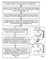
- FIG. 2 sets forth a flow chart illustrating an example method of data communications among electronic devices within a computer according to embodiments of the present invention.
- FIG. 3 sets forth a functional block diagram illustrating an arrangement of devices capable of carrying out an example method of data communications among electronic devices within a computer according to embodiments of the present invention.
- FIG. 4 sets forth a flow chart illustrating a further example method of data communications among electronic devices within a computer according to embodiments of the present invention.
- FIG. 5 sets forth a flow chart illustrating a further example method of data communications among electronic devices within a computer according to embodiments of the present invention.
- FIG. 6 sets forth a flow chart illustrating a further example method of data communications among electronic devices within a computer according to embodiments of the present invention.
- FIG. 7 sets forth a flow chart illustrating a further example method of data communications among electronic devices within a computer according to embodiments of the present invention.
- FIG. 1 sets forth a block diagram of automated computing machinery that includes an example computer ( 152 ) useful in data communications among electronic devices within a computer according to embodiments of the present invention.
- the computer ( 152 ) of FIG. 1 includes at least one computer processor ( 156 ) or ‘CPU’ as well as random access memory ( 168 ) (‘RAM’) which is connected through a high speed memory bus ( 166 ) and bus adapter ( 158 ) to processor ( 156 ) and to other components of the computer ( 152 ).
- processor 156
- RAM random access memory
- RAM ( 168 ) Stored in RAM ( 168 ) is an application program ( 150 ), a module of user-level computer program instructions for performing a specific function directly for a user or, in some cases, for another application program. Examples of application programs include word processors, database programs, spreadsheets, browsers, and so on. Also stored in RAM ( 168 ) is an operating system ( 154 ). Operating systems useful data communications among electronic devices within a computer according to embodiments of the present invention include UNIXTM, LinuxTM, Microsoft XPTM, AIXTM, IBM's i5/OSTM, and others as will occur to those of skill in the art. The operating system ( 154 ) and the application program ( 150 ) in the example of FIG. 1 are shown in RAM ( 168 ), but many components of such software typically are stored in non-volatile memory also, such as, for example, on a disk drive ( 170 ).
- the computer of FIG. 1 also includes a transmitting device ( 104 ), a receiving device ( 110 ), a first translation device ( 106 ), and a second translation device ( 108 ).
- the transmitting device ( 104 ) and the first translation device ( 106 ) are coupled for data communications by a wireline data communications bus ( 213 ), and the receiving device ( 110 ) and the second translation device ( 108 ) are coupled for data communications by a wireline data communications bus ( 214 ).
- the wireline data communications buses ( 213 , 214 ) may optionally be the same kind of wireline data communications bus, or not.
- a wireline data communications bus ( 213 , 214 ) is a subsystem that facilitates data communications between computer components inside a computer or between computers over one or more wires.
- a wireline data communications bus may be embodied, for example, as an I 2 C bus, a Serial Peripheral Interface (‘SPI’) bus, a System Management Bus (‘SMBus’), a IEEE 1149.1 (‘JTAG’) boundary scan bus, or as an any other wireline bus as may occur to those of skill in the art.
- Data communications over these wireline data communications buses ( 213 , 214 ) are carried out according to an unreliable data communications protocol. Such protocols are unreliable in the sense that the protocol does not ensure that data will be delivered intact or delivered at all.
- An unreliable wireline data communications protocol is unreliable in the sense that the protocol presents an attempt to deliver data but provides no mechanism to verify data arrives without error.
- the transmitting device ( 104 ) and the receiving device ( 110 ) can be implemented as any device capable of data communications over a wireline data communications bus according to an unreliable data communications protocol.
- Whether a particular device is a transmitting device or a receiving device is a matter of usage.
- whether a particular device is referred to as a ‘transmitter’ or as a ‘receiver’ depends on its role or function at a particular point in time, whether the device is presently sending or receiving.
- Such transmitting devices and receiving devices may be implemented as, for example, microprocessors, microcontrollers, low-speed peripherals, special purpose sensors, ADCs, DACs, memory modules, I/O modules, power supplies, system clocks, and other devices as will occur to those of skill in the art.
- Such transmitting devices and receiving devices may includes, for further examples, I 2 C master devices, I 2 C slave devices, a JTAG boundary scan device, an SPI master device, an SPI slave device, an SMBus master device, an SMBus slave device, and so on.
- the transmitting device ( 104 ) and the receiving device ( 110 ) in this example are coupled also through wireline buses ( 211 , 217 ) to the computer processor ( 156 ) and the RAM ( 168 ) respectively, so that the transmitting device and the receiving device can exchange instructions or operating information, for example, between the computer processor ( 156 ) and the RAM ( 168 ).
- the transmitting device ( 104 ) and the receiving device ( 110 ) are shown, with respect to the processor ( 156 ) and the RAM ( 168 ), as separate devices, although in other example embodiments, the transmitting device or the receiving device will be incorporated into another device, such as, for example, a processor, a memory module, and so on.
- a translation device is an automated electronic device composed of synchronous or asynchronous logic and electrical interconnections capable of translating data communications encoded in one data communications protocol into data communications encoded in another communications protocol, including translating data communications between an unreliable wireline data communications protocol encoding and a reliable wireless data communications protocol encoding.
- Such a translation device can include a serial interface for connecting to a wireline data communications bus, translation logic that carries out encodings from one protocol to another, and a differential pair or single wire interface for wireless data communications.
- Data communications according to embodiments of the present invention typically is carried out by use of two or more translation devices, so that, for clarity of explanation in this specification, a translation device is sometimes referred to as a ‘first’ translation device or a ‘second’ translation device.
- the use of the terms ‘first’ and ‘second,’ is only an aid to explanation, not a technical feature of apparatus that carries out data communications according to embodiments of the present invention.
- a translation device ( 106 , 108 ) is an automated electronic device composed of synchronous or asynchronous logic and electrical interconnections capable of translating data communications encoded in one data communications protocol into data communications encoded in another communications protocol.
- Such a translation device can include a serial interface for connecting to a wireline data communications bus, translation logic that carries out encodings from one protocol to another, and a differential pair or single wire interface for wireless data communications.
- Data communications according to embodiments of the present invention typically are carried out by use of two or more translation devices, so that, for clarity of explanation in this specification, a translation device is sometimes referred to as a ‘first’ translation device or a ‘second’ translation device.
- each translation device ( 106 , 108 ) is coupled for data communications over a wireless data communications connection ( 215 ).
- a wireless connection may be implemented, for example, as a Wireless USB connection, a wireless TCP/IP connection, or in any way as will occur to those of skill in the art.
- the transmitting device ( 104 ), the receiving device ( 110 ), the first translation device ( 106 ), and the second translation device ( 108 ) are disposed within the computer on a printed circuit board (‘PCB’) ( 102 ) along with the processor, the RAM module, a bus adapter, a video adapter, and several buses ( 162 , 166 , 160 , 164 ), as well as other components of the computer not illustrated here.
- the processor ( 156 ) and the RAM module ( 168 ) communicate with one another through the transmitting device ( 104 ) and the receiving device ( 110 ), but the processor and the RAM module are widely separated from one another on the PCB ( 102 ).
- the transmitting device and the receiving device would be connected, along with other devices, by a large-topology wireline bus (using an unreliable protocol) that would include multiple drops, tees, and switches, greatly increasing the likelihood of communications failures.
- the transmitting device ( 104 ), the receiving device ( 110 ), the first translation device ( 106 ), and the second translation device ( 108 ) operate together to carry out data communications among electronic devices within the computer ( 152 ), according to embodiments of the present invention, in this fashion:
- the transmitting device transmits to the first translation device data communications encoded according to an unreliable wireline data communications protocol.
- Such data communication can include, for example, operating instructions from a processor to a RAM module, requests for operating information directed from a processor to a RAM module, instructions from a processor to a system clock to changes speeds, instructions from a processor to a power supply to change power settings, and so on.
- the first translation device translates the data communications from the encoding of the unreliable wireline data communications protocol to an encoding of a reliable wireless data communications protocol.
- a translation of encoding may be represented by, for example, a translation from I 2 C encoding to Wireless USB encoding, from SPI encoding to Wireless Ethernet encoding, and so on.
- the first translation device then transmits, to the second translation device, the data communications according to the reliable wireless data communications protocol, and the second translation device translates the data communications back, from the encoding of the reliable wireless data communications protocol, to the encoding of the unreliable wireline data communications protocol.
- the second translation device then transmits the data communications to the receiving device according to the unreliable wireline data communications protocol.
- the computer ( 152 ) of FIG. 1 includes disk drive adapter ( 172 ) coupled through expansion bus ( 160 ) and bus adapter ( 158 ) to processor ( 156 ) and other components of the computer ( 152 ).
- Disk drive adapter ( 172 ) connects non-volatile data storage to the computer ( 152 ) in the form of disk drive ( 170 ).
- Disk drive adapters useful in computers for data communications among electronic devices within a computer according to embodiments of the present invention include Integrated Drive Electronics (‘IDE’) adapters, Small Computer System Interface (‘SCSI’) adapters, and others as will occur to those of skill in the art.
- IDE Integrated Drive Electronics
- SCSI Small Computer System Interface
- Non-volatile computer memory also may be implemented for as an optical disk drive, electrically erasable programmable read-only memory (so-called ‘EEPROM’ or ‘Flash’ memory), RAM drives, and so on, as will occur to those of skill in the art.
- EEPROM electrically erasable programmable read-only memory
- Flash RAM drives
- the example computer ( 152 ) of FIG. 1 includes one or more input/output (‘I/O’) adapters ( 178 ).
- I/O adapters implement user-oriented input/output through, for example, software drivers and computer hardware for controlling output to display devices such as computer display screens, as well as user input from user input devices ( 181 ) such as keyboards and mice.
- the example computer ( 152 ) of FIG. 1 includes a video adapter ( 209 ), which is an example of an I/O adapter specially designed for graphic output to a display device ( 180 ) such as a display screen or computer monitor.
- Video adapter ( 209 ) is connected to processor ( 156 ) through a high speed video bus ( 164 ), bus adapter ( 158 ), and the front side bus ( 162 ), which is also a high speed bus.
- the example computer ( 152 ) of FIG. 1 includes a communications adapter ( 167 ) for data communications with other devices ( 182 ). Such data communications may be carried out serially through RS-232 connections, through external buses such as a Universal Serial Bus (‘USB’), through data communications data communications networks such as IP data communications networks, and in other ways as will occur to those of skill in the art.
- Communications adapters implement the hardware level of data communications through which one computer sends data communications to another computer, directly or through a data communications network. Examples of communications adapters useful for data communications among electronic devices within a computer according to embodiments of the present invention include modems for wired dial-up communications, Ethernet (IEEE 802.3) adapters for wired data communications network communications, and 802.11 adapters for wireless data communications network communications.
- Automated computing machinery useful according to various embodiments of the present invention may include additional servers, routers, other devices, and peer-to-peer architectures, not shown in FIG. 1 , as will occur to those of skill in the art.
- Networks in such data processing systems may support many data communications protocols, including for example TCP (Transmission Control Protocol), IP (Internet Protocol), HTTP (HyperText Transfer Protocol), WAP (Wireless Access Protocol), HDTP (Handheld Device Transport Protocol), and others as will occur to those of skill in the art.
- Various embodiments of the present invention may be implemented on a variety of hardware platforms in addition to those illustrated in FIG. 1 .
- FIG. 2 sets forth a flow chart illustrating an example method of data communications among electronic devices within a computer ( 152 ) according to embodiments of the present invention.
- the term “computer” is used here in the broad sense of automated computing machinery, including, for example, motherboards on personal computers or laptops, personal digital assistants, motherboards on blade servers and other servers, computer components on embedded systems, cellular phones, other automated handheld devices, and so on, as will occur to those of skill in the art.
- Such a computer ( 152 ) can be, for example, similar to the one described above with reference to FIG. 1 .
- the electronic devices within the computer are connected together through an administrative, low-bandwidth network, such as, for example, I 2 C or SMBus, that is improved by inclusion of translation devices for wireless data communications according to embodiments of the present invention by inclusion.
- the administrative, low-bandwidth network such as I 2 C or SMBus, is referred to in this specification as a wireline data communications bus.
- the method of FIG. 2 includes transmitting ( 202 ), from a transmitting device ( 104 ) to a first translation device ( 106 ), data communications ( 212 ) encoded according to an unreliable wireline data communications protocol, to the first translation device by a wireline data communications bus ( 213 ).
- the transmitting device ( 104 ) and the first translation device ( 106 ) are electronic components of a computer ( 152 ), where the transmitting device is coupled for data communications to the first translation device by a wireline data communications bus ( 213 ).
- a wireline data communications bus is a subsystem that facilitates data communications between computer components inside a computer or between computers over one or more wires.
- data communications ( 212 ) over such wireline data communications buses are carried out according to an unreliable data communications protocol.
- the method of FIG. 2 includes translating ( 204 ), by the first translation device ( 106 ), the data communications ( 212 ) from the encoding of the unreliable wireline data communications protocol to an encoding of a reliable wireless data communications protocol.
- a reliable wireless data communications protocol is a protocol that implements at least some mechanism to verify that data is communicated without transmission errors, corruption, tampering, incorrect bits, dropped packets, and so on. Such mechanisms for message security include checksums, encryption, sequence numbering of packets within a message, and so on. Examples of reliable wireless protocols include Wireless USB, TCP/IP over wireless Ethernet, and so on. Verifying that data arrived without error can be carried out, for example, by including a checksum in a data transmission.
- a checksum is generated by adding numeric values of components of a message and storing the total as a ‘checksum.’
- the recipient of data communications can verify that data arrived without error by performing the same operation on the message and comparing the result to the checksum. If the result of addition by the recipient matches the checksum, the recipient concludes that the message arrived without corruption during transmission.
- translating the data communications from the encoding of the unreliable wireline data communications protocol to an encoding of a reliable wireless data communications protocol is carried out by the first translation device ( 106 ), which is capable of data communications according to the unreliable wireline data communications protocol and also capable of data communications according to the reliable wireless data communications protocol.
- the first translation device ( 106 ) carries out such a translation by decoding data communications ( 212 ) encoded in the unreliable wireline data communications protocol into a sequence of digital bits. Such a sequence of digital bits is subsequently encoded by the first translation device ( 106 ) according to a reliable wireless data communications protocol such that the sequence of digital bits is preserved but encoded according to a different data communications protocol.
- the method of FIG. 2 includes transmitting ( 206 ), by the first translation device ( 106 ) to a second translation device ( 108 ), the data communications ( 218 ) according to the reliable wireless data communications protocol.
- transmitting data can be carried out, for example, by the first translation device ( 106 ) initiating a wireless data communications session with the second translation device ( 108 ) and sending the translated data communications ( 218 ) to the second translation device during the data communications session. Because the translated data communications is sent over a reliable wireless data communications protocol, the data communications ( 218 ) is checked for errors such as, for example, bit corruption or packet loss. If an error is detected, a number of actions may be taken in response including retransmitting the data communications from the first translation device ( 106 ) to the second translation device ( 108 ).
- the method of FIG. 2 includes translating ( 208 ), by the second translation device ( 108 ), the data communications ( 218 ) from the encoding of the reliable wireless data communications protocol to the encoding of the unreliable wireline data communications protocol.
- the second translation device ( 108 ) is capable of data communications according to the unreliable wireline data communications protocol and also capable of data communications according to the reliable wireless data communications protocol.
- the second translation device ( 108 ) carries out such a translation by decoding data communications ( 218 ) encoded in the reliable wireless data communications protocol into a sequence of digital bits. Such a sequence of digital bits is subsequently encoded by the second translation device according to the unreliable wireline data communications protocol such that the sequence of digital bits is preserved but encoded according to a different data communications protocol.
- the method of FIG. 2 includes transmitting ( 210 ), by the second translation device ( 108 ) to a receiving device ( 110 ), the data communications ( 212 ) according to the unreliable wireline data communications protocol.
- the receiving device ( 110 ) and the second translation device ( 108 ) are electronic components of the computer ( 152 ), the receiving device coupled for data communications to the second translation device by a wireline data communications bus ( 214 ).
- transmitting data can be carried out, for example, by the second translation device ( 108 ) initiating a wireline data communications session with the receiving device ( 110 ) and sending the translated data communications ( 212 ) to the receiving device during the data communications session. Because the translated data communications is sent over an unreliable wireless data communications protocol, the data communications is not checked for errors.
- FIG. 3 sets forth a functional block diagram illustrating an arrangement of devices capable of carrying out data communications among electronic devices within a computer according to embodiments of the present invention.
- the example of FIG. 3 is similar to the example of FIG. 1 , including as it does, a transmitting device ( 104 ), a receiving device ( 110 ), a first translation device ( 106 ), and a second translation device ( 107 , 108 ).
- the transmitting device ( 104 ) and the receiving devices ( 110 ) are connected to the translation devices ( 106 , 107 , 108 ) by wireline buses ( 322 ).
- each translation device ( 106 , 107 , 108 ) includes translation logic ( 305 ).
- Translation logic ( 305 ) is synchronous or asynchronous logic circuitry configured to translate data communications between encodings according to unreliable wireline data communications protocols and encodings according to reliable wireless data communications protocols.
- Translation logic ( 305 ) may be embodied as a field-programmable gate arrays (‘FPGAs’), complex programmable logic devices (‘CPLDs’), application specific integrated circuits (‘ASICs’), and in other ways as will occur to those of skill in the art.
- FPGAs field-programmable gate arrays
- CPLDs complex programmable logic devices
- ASICs application specific integrated circuits
- one of the translation devices ( 107 ) includes a data communications switch ( 320 ).
- a data communications switch ( 320 ) is programmable logic capable of routing data communications to one or more of the devices ( 110 ) connected to a translation device ( 107 ) that includes such a data communications switch
- the wireline data communications bus is an I 2 C bus.
- An I 2 C bus is a wireline data communications bus that includes two bidirectional open-drain lines that carry information among devices connected to the bus, a serial data line ( 304 ) and a serial clock line ( 306 ).
- a serial data line 304
- a serial clock line 306
- signals on a bus ( 322 ) between the master and a translation device ( 106 ) are transmitted directly to and received directly a slave device ( 104 ); and, from the perspective of a slave device ( 110 ), signals on a bus ( 322 ) between a slave device and a translation device ( 107 , 108 ) are transmitted directly to and received directly from a master device ( 104 ).
- the intervening translation and transmission according to a reliable protocol is completely unknown to the transmitting ( 104 ) and receiving devices ( 110 ), in this example, an I 2 C master and I 2 C slaves.
- Data to be transferred between the transmitting device ( 104 ) and the first translation device ( 106 ) is placed on the data line ( 304 ) which must be stable when the clock line ( 306 ) is in the HIGH voltage state.
- the state of the data line can only change when the clock signal on the clock line is LOW.
- bits of data to be transferred between the transmitting device ( 104 ) and the first translation device ( 106 ) can be represented, for example, by the HIGH and LOW voltage states on the data line ( 304 ).
- data communications on the I2C buses are carried out according to the I 2 C protocol, an unreliable wireline data communications protocol.
- the I 2 C bus protocol is a serial computer bus protocol for connecting electronic components inside a computer that is unreliable in the sense that it does supports no form of error checking, including, for example, parity checking, cyclic redundancy checking, error-correcting codes, and so on.
- error checking including, for example, parity checking, cyclic redundancy checking, error-correcting codes, and so on.
- the complex intervening bus structures are replaced with a wireless transmission medium ( 312 ), more reliable than a complex wireline bus, upon which is utilized a reliable data communication protocol.
- the example apparatus of FIG. 3 implements a reliable wireless data communications protocol as the Wireless Universal Serial Bus (‘WUSB’) protocol ( 313 ).
- the WUSB protocol is a short-range wireless radio communication protocol that governs the connection, communication, and data transfer between a WUSB hub and WUSB devices.
- the WUSB protocol includes, for example, regulations regarding the formatting of WUSB packets and requirements regarding flow control between communicating devices.
- Each translation device ( 106 , 107 , 108 ) includes either a WUSB Hub ( 324 ) or a WUSB device ( 326 , 328 ).
- Each WUSB Hub ( 324 ) and WUSB device ( 326 , 328 ) receives data communications through WUSB wireless links ( 312 ) according to the WUSB data communications protocol and hands off all such communications to a module of translation logic ( 305 ) for translation to I 2 C encoding.
- Each WUSB Hub ( 324 ) and WUSB device ( 326 , 328 ) receives from a module of translation logic ( 305 ) data communications that have been translated to WUSB encoding from I 2 C encoding and transmits those data communications through the WUSB wireless links ( 312 ) according to the WUSB data communications protocol.
- the transmitting device ( 104 ) is an I 2 C master device and the receiving device ( 110 ) is an I 2 C slave device.
- An I 2 C master device is a device capable of data communications over an I 2 C bus ( 322 ) that initiates data communications by sending a start bit. Such a master device identifies a slave device ( 110 ) with which it wishes to initiate communication.
- An I 2 C slave device ( 110 ) is a device capable of receiving data communications over an I 2 C bus ( 322 ) in response to the master device's request to initiate data communications with the slave device.
- Such a slave device ( 110 ) begins communications with a master device by responding with an ACK bit in response to a master device's request to initiate data communications with the slave device.
- the first translation device ( 106 ) exposes an I 2 C slave interface ( 308 ) to the transmitting device ( 104 ) and a second translation device ( 107 , 108 ) exposes an I 2 C master interface ( 316 ) to the receiving device ( 110 ).
- An I 2 C slave interface includes a set of pins that enables a master device to physically connect to the data line ( 304 ) and the clock line ( 306 ) of an I 2 C bus ( 322 ). Through such a physical connection, the I 2 C master device is able to affect line level changes to the state of the data line ( 304 ) and clock line ( 306 ) such as, for example, affecting a change in the voltage level across each line.
- An I 2 C master interface ( 318 ) is a set of pins that enables a slave device to physically connect to the data line ( 304 ) and the clock line ( 306 ) of an I 2 C bus ( 322 ). Through such a physical connection, the I 2 C slave device is able to affect line level changes to the state of data line ( 304 ) and clock line ( 306 ) such as, for example, affecting a change in the voltage level across the data line ( 304 ) and clock line ( 306 ).
- the first translation device ( 106 ) exposes a wireless USB hub interface ( 310 ) to a second translation device ( 107 , 108 ) and a second translation device exposes a wireless USB spoke interface ( 316 ) to the first translation device.
- Wireless USB is a logical bus that supports data communications between a host device and one or more peripherals.
- a wireless USB hub interface serves as a connection point through which a wireless USB device can connect to a wireless USB host.
- a wireless USB spoke interface serves as a connection point through which a wireless USB host can communicate with a wireless USB device.
- Wireless USB devices attach to a host by sending the host a message at a well defined time. The host and device then authenticate each other using unique IDs and the appropriate security keys.
- the transmitting device ( 104 ), the receiving device ( 110 ), the first translation device ( 106 ), and the second translation device ( 108 ) operate together to carry out data communications among electronic devices within a computer, according to embodiments of the present invention, in this fashion:
- the first translation device ( 106 ) receives the communications through I 2 C interface ( 308 ), translates, by its translation logic module ( 305 ), the data communications from the encoding of the I 2 C protocol to an encoding of the reliable WUSB wireless data communications protocol.
- the first translation device then transmits, to the second translation device, by its WUSB Hub ( 324 ) through its WUSB interface ( 310 ), the data communications according to the reliable WUSB wireless data communications protocol.
- a second translation device ( 107 or 108 ) translates the data communications back, from the encoding of the reliable WUSB protocol to the encoding of the unreliable I 2 C protocol.
- the second translation device then transmits the data communications, through an I 2 C interface ( 318 ) across an I 2 C bus ( 322 ), to a receiving device ( 110 ) according to the unreliable wireline data communications protocol.
- FIG. 4 sets forth a flow chart illustrating a further example method of data communications among electronic devices within a computer according to embodiments of the present invention.
- the method of FIG. 4 is similar to the method of FIG. 2 , including as it does transmitting ( 202 ) data communications to the first translation device, translating ( 204 ) the data communications by the first translation device, transmitting ( 206 ) the data communications to the second translation device, translating ( 208 ) the data communications by the second translation device, and transmitting ( 210 ) the data communications by the second translation device.
- the unreliable wireline data communications protocol is the Inter-Integrated Circuit (‘I2C’) protocol
- the reliable wireless data communications protocol is the Wireless Universal Serial Bus (‘WUSB’) protocol
- the wireline data communications buses are I2C buses.
- transmitting ( 202 ) data communications from a transmitting device to a first translation device includes transmitting ( 402 ) communications ( 412 ) from a transmitting device ( 104 ) to a first translation device ( 106 ) according to the I 2 C protocol.
- Data transmissions according to the I 2 C protocol are permitted only when the I 2 C bus ( 418 ) is free.
- the I 2 C bus is free when both the data line and the clock line are in the HIGH state.
- the transmitting device ( 104 ) creates a START condition by pulling the data line low while the clock line remains in the HIGH state. After such a START condition has occurred, the bus is no longer free.
- the transmitting device ( 104 ) begins data transmission by iteratively pulling the clock line low, pulling low or releasing the data line as appropriate, and then releasing the clock line.
- the transmitting device can create a STOP condition by transitioning the data line from the LOW state to the HIGH state while the clock line is in the HIGH state.
- translating ( 204 ) the data communications from the encoding of the unreliable wireline data communications protocol to an encoding of a reliable wireless data communications protocol includes translating ( 404 ) the data communications ( 412 ) from an I 2 C encoding to a wireless USB encoding.
- translating the data communications ( 412 ) from an I 2 C encoding to a wireless USB encoding can be carried out by measuring the voltage levels across the data line and clock line and outputting a digital value that represents data communications across the data line and clock line. In an I 2 C encoding data values are read from the data line after the clock line transitions from the LOW state to the HIGH state.
- a digital ‘1’ has been transferred. If the data line is at the LOW state a digital ‘0’ has been transferred. After all bits of data have been received from an I 2 C encoded data communications session, such values are packetized according to the wireless USB protocol.
- the general structure of a wireless USB packet is that is contains a preamble, headers, and data which can be transmitted at a different rate than the headers.
- transmitting ( 206 ) the data communications by the first translation device ( 106 ) to a second translation device ( 108 ) includes transmitting the data communications ( 414 ) by the first translation device ( 106 ) to a second translation device ( 108 ) according to the WUSB protocol.
- Data communications ( 414 ) according to the WUSB protocol occur over channels through which bit streams are transmitted and received. Such bit streams are encoded into packets by a sender and encoded out of packets by a receiver. Transmitting the data communication by the first translation device ( 106 ) can therefore be carried out by transmitting the wireless USB packet created above over a channel to the second translation device ( 108 ).
- the second translation device ( 108 ) receives the USB packet intact, the second translation device will subsequently acknowledge receipt of the packet. If the packet is not received intact, WUSB rules for recovering lost packets will be invoked. In such a way, the WUSB protocol guarantees advancement of a data stream only after reliable data delivery.
- translating ( 206 ) the data communications from the encoding of the reliable wireless data communications protocol to the encoding of the unreliable wireline data communications protocol includes translating ( 408 ) the data communications ( 412 ) from the WUSB encoding to the I 2 C encoding.
- Translating ( 408 ) the data communications ( 412 ) from the WUSB encoding to the I 2 C encoding may be carried out, for example, by translating the WUSB encoding into a sequence of bits and affecting a sequence of signal level changes according to the I 2 C protocol that correspond to such a sequence of bits.
- the second translation device ( 108 ) will initially attempt to create a START condition by pulling the data line low.
- the second translation device can begin data transmission.
- the second translation device must first pull the clock line low.
- the second translation device can then pull the data line LOW if the second translation device is transferring a digital ‘0’ or the second translation device can release the data line if the second translation device is transferring a ‘1’.
- the second translation device ( 108 ) must then release the clock line as the data line will be sampled by the receiving device ( 110 ) when the clock line is in the HIGH state.
- the second translation device ( 108 ) can continue data translation in such a manner.
- the second translation device can transition the data line from the LOW state to the HIGH state while the clock line is in the HIGH state, indicating a STOP condition.
- transmitting ( 210 ) the data communications by the second translation device to a receiving device includes transmitting ( 410 ) the data communications ( 412 ) by the second translation device ( 108 ) to a receiving device ( 110 ) according to the I 2 C protocol.
- Data transmissions according to the I 2 C protocol are permitted only when the I 2 C bus ( 420 ) is free.
- the I 2 C bus is free when both the data line and the clock line are in the HIGH state.
- the second translation device ( 108 ) creates a START condition by pulling the data line low while the clock line remains HIGH. After such a START condition has occurred, the bus is no longer free.
- the second translation device ( 108 ) begins data transmission by iteratively pulling the clock line low, pulling low or releasing the data line as appropriate, and then releasing the clock line.
- the second translation device ( 108 ) can create a STOP condition by transitioning the data line from the LOW state to the HIGH state while the clock line is in the HIGH state.
- FIG. 5 sets forth a flow chart illustrating a further example method of data communications among electronic devices within a computer according to embodiments of the present invention.
- the method of FIG. 5 is similar to the method of FIG. 2 , including as it does transmitting ( 202 ) data communications to the first translation device ( 104 ), translating ( 204 ) the data communications by the first translation device, transmitting ( 206 ) the data communications to the second translation device ( 108 ), translating ( 208 ) the data communications by the second translation device, and transmitting ( 210 ) the data communications by the second translation device.
- the example method of FIG. 5 also like the method of FIG. 2 , typically is implemented on a computer similar to the one described above with reference to FIG. 1 . In the method of FIG.
- the encoding of the unreliable wireline protocol includes an encoding of digital bits as signal level transitions ( 508 ).
- a signal level transition is a change to the state of a wireline including, for example, a change in the voltage level across a wireline.
- Encoding digital bits as signal level transitions can be carried out, for example, by changing the state of a wireline at predefined intervals to reflect a particular sequence of digital bits. For example, a voltage of 5V across a wireline may represent a bit value of 1 and a voltage of 3V across a wireline may represent a value of 0.
- a digital bit sequence of ‘1101’ can be encoded as signal level transitions by affecting voltage levels of 5V, 5V, 3V, and 5V across a wireline at successive intervals.
- the encoding of the reliable wireless protocol includes an encoding of digital bits as digital values ( 512 ).
- digital values may be embodied, for example, as binary values, hexadecimal values, or in any other way as will occur to those of skill in the art.
- Encoding digital bits as digital values can be carried out, for example, by creating a digital value that represents a sequence of digital bits. For example, if a digital bit sequence of ‘1101’ is received, such digital bits can be encoded as a hexadecimal value of ‘D’.
- translating ( 204 ), by the first translation device ( 106 ), the data communications ( 506 ) from the encoding of the unreliable wireline protocol to an encoding of a reliable wireless protocol includes translating ( 502 ) signal level transitions ( 508 ) of the unreliable wireline protocol into digital values of the reliable wireless protocol.
- translating ( 502 ) signal level transitions of the unreliable wireline protocol into digital values may be carried out, for example, by measuring the voltage levels across the data line and clock line of a wireline bus ( 214 ) and outputting a digital value that represents data communications across the data line and clock line.
- the first translation device ( 106 ) will initially wait for a START condition from the transmitting device ( 104 ) before translating the signal level transitions.
- a START condition occurs when the data line transitions from the HIGH to LOW state at the same time that the clock line is in the HIGH state.
- the first translation device ( 106 ) begins to translate the signal level transitions that follow.
- the first translation device ( 106 ) measures the voltage level across the data line. If the data line is at the HIGH state the first translation device determines that a digital ‘1’ has been transferred.
- the first translation device determines that a digital ‘0’ has been transferred.
- the first translation device ( 106 ) continues to detect the sequence of transmitted bits until the first translation device detects that the data line has transitioned from the LOW state to the HIGH state while the clock line is at the HIGH state, indicating a STOP condition.
- the first translation device ( 106 ) can then packetize such a sequence of bits into the format required by the reliable wireless protocol, including translating the digital bits as digital values ( 512 ).
- translating ( 208 ), by the second translation device ( 108 ), the data communications ( 506 ) from the encoding of the reliable wireless protocol to the encoding of the unreliable wireline protocol includes translating ( 504 ) digital values ( 512 ) of the reliable wireless protocol into signal level transitions ( 508 ) of the unreliable wireline protocol.
- translating digital values into signal level transitions may be carried out, for example, by translating the digital values into a sequence of bits and affecting a sequence of signal level changes that correspond to such a sequence of bits.
- the second translation device ( 108 ) will initially attempt to create a START condition by pulling the data line low.
- the second translation device ( 108 ) can begin data transmission.
- the second translation device ( 108 ) must first pull the clock line low.
- the second translation device can then pull the data line low if the second translation device is transferring a digital ‘0’ or the second translation device can release the data line if the second translation device is transferring a ‘1’.
- the second translation device ( 108 ) must then release the clock line as the data line will be sampled by the receiving device ( 110 ) when the clock line is in the HIGH state.
- the second translation device ( 108 ) can continue data translation in such a manner.
- the second translation device can transition the data line from the LOW state to the HIGH state while the clock line is in the HIGH state, indicating a STOP condition.
- FIG. 6 sets forth a flow chart illustrating a further example method of data communications among electronic devices within a computer according to embodiments of the present invention.
- the method of FIG. 6 is similar to the method of FIG. 2 , including as it does transmitting ( 202 ) data communications to the first translation device ( 106 ), translating ( 204 ) the data communications ( 212 ) by the first translation device, transmitting ( 206 ) the data communications to the second translation device ( 108 ), translating ( 204 ) the data communications ( 218 ) by the second translation device, and transmitting ( 210 ) the data communications ( 218 ) by the second translation device ( 107 ).
- the example method of FIG. 6 also like the method of FIG.
- the translation devices ( 107 ) typically is implemented on a computer ( 152 ) similar to the one described above with reference to FIG. 1 .
- at least one of the translation devices ( 107 ) includes a data communications switch ( 320 ).
- the translation device ( 107 ) that includes a data communications switch ( 320 ) is connected to a plurality of receiving devices ( 110 ) that include the receiving device ( 110 ).
- each of the plurality of receiving devices is separately connected to the translating device by a separate wireline data communications bus ( 214 , 219 ).
- a separate wireline data communications bus ( 214 , 219
- a translation device ( 107 ) that includes a data communications switch ( 320 ) can route data communications to any of the plurality of receiving devices ( 110 ) connected to the translation device ( 107 ).
- the switch ( 320 ) can be implemented as an electronic multiplexer, as an address decoder, and in other ways that may occur to those of skill in the art.
- the transmitting device ( 104 ) instructs ( 602 ) the translation device, that is, the translation device ( 107 ) that includes a data communications switch ( 320 ), to set the switch to direct communications from the transmitting device ( 104 ) to a receiving device ( 110 ) through the translation device ( 107 ) that includes the data communications switch ( 302 ).
- the transmitting device ( 104 ) can instruct the translation device ( 107 ) that includes a switch ( 320 ) to direct communications from the transmitting device to a particular receiving device by, for example, sending the translation device a target device instruction ( 604 ).
- a target device instruction ( 604 ) is a data communications message ( 604 ) instructing the translation device that any data communications received from the transmitting device should be directed to an identified receiving device until further notice.
- Such an instruction can include, for example, the network address or other identifier of a targeted receiving device ( 110 ).
- FIG. 7 sets forth a flow chart illustrating a further example method of data communications among electronic devices within a computer according to embodiments of the present invention.
- the method of FIG. 7 is similar to the method of FIG. 2 , including as it does transmitting ( 202 ) data communications to the first translation device, translating ( 204 ) the data communications by the first translation device, transmitting ( 206 ) the data communications to the second translation device, translating ( 208 ) the data communications by the second translation device, and transmitting ( 210 ) the data communications by the second translation device.
- the example method of FIG. 7 also like the method of FIG. 2 , typically is implemented on a computer ( 152 ) similar to the one described above with reference to FIG. 1 . In the method of FIG.
- the second translation device ( 108 ) can determine that the receiving device ( 110 ) is holding the signal level on such a wireline data communications bus ( 214 ) low by, for example, monitoring the voltage level across the wireline bus ( 214 ).
- a receiving device ( 110 ) may pull the wireline bus ( 214 ) low, for example, to stretch a clock period when the receiving device is not yet ready to receive additional data communications.
- the second translation device can advise ( 702 ) the first translation device ( 106 ) that the receiving device ( 110 ) is holding the signal level low by, for example, sending a message to first translation device ( 106 ).
- the method of FIG. 7 also includes holding ( 704 ) low, by the first translation device ( 106 ), a corresponding wireline ( 213 ) between the first translation device and the transmitting device ( 104 ) until the second translation device ( 108 ) advises that the receiving device ( 110 ) no longer holds low the wireline ( 214 ) between the second translation device and the receiving device.
- the first translation device ( 106 ) advises the transmitting device ( 104 ) to hold data communications for the remainder of the stretched clock period.
- the first translation device ( 214 ) will hold the wireline low until the second translation device ( 108 ) advises the first translation device ( 106 ) that the receiving device ( 110 ) no longer holds low the wireline ( 214 ) between the second translation device and the receiving device.
- the first translation device can be advised that the receiving device ( 110 ) no longer holds low the wireline ( 214 ) between the second translation device and the receiving device, for example, by receiving a message from the second translating device ( 108 ). As such, the receiving device will not receive additional data communications until the receiving device no longer holds the signal low, thereby indicating that the receiving device is ready to receive data communications.
- Example embodiments of the present invention are described largely in the context of a fully functional computer system for data communications among electronic devices within a computer. Readers of skill in the art will recognize, however, that the present invention also may be embodied in a computer program product disposed on signal bearing media for use with any suitable data processing system.
- signal bearing media may be transmission media or recordable media for machine-readable information, including magnetic media, optical media, or other suitable media. Examples of recordable media include magnetic disks in hard drives or diskettes, compact disks for optical drives, magnetic tape, and others as will occur to those of skill in the art.
- transmission media examples include telephone networks for voice communications and digital data communications networks such as, for example, EthernetsTM and networks that communicate with the Internet Protocol and the World Wide Web as well as wireless transmission media such as, for example, networks implemented according to the IEEE 802.11 family of specifications.
- any computer system having suitable programming means will be capable of executing the steps of the method of the invention as embodied in a program product.
- Persons skilled in the art will recognize immediately that, although some of the example embodiments described in this specification are oriented to software installed and executing on computer hardware, nevertheless, alternative embodiments implemented as firmware or as hardware are well within the scope of the present invention.
Abstract
Description
-
- Because each transmitting and receiving device in the present application is connected directly to a translation device, wireline bus topologies are simplified as each wireline may connects a reduced number of devices—optionally as little as two devices, a translation device and a transmitting or receiving device. As such, there is reduced failure across wireline busses in the present application and communication between transmitting devices and receiving devices becomes more reliable given that wireless communications are reliable and the wireline communications are less prone to failure than in a system in which all devices are connected by a wireline bus.
- The topology of wireline connections to and from transmitting and receiving devices that communicate according to embodiments of the present invention is greatly simplified for a same number of communicating devices. An entire wireline network is now interspersed with wireless segments, resulting in wireline topologies that, from the perspective of the transmitting and receiving devices, often can appear as a single wireline connection. The risk of failure in complex wireline topologies that connect many devices with multiple drops, tees, and switches is greatly reduced.
- Transmitting and receiving devices that communicate data according to embodiments of the present invention can occupy the entire address space of a wireline data communications protocol—unlike prior art communications among devices within a computer where transmitting device could drive through a complex wireline topology receiving devices whose addresses occupy even a substantial portion of the address space supported by a protocol, much less the entire address space.
Claims (15)
Priority Applications (1)
| Application Number | Priority Date | Filing Date | Title |
|---|---|---|---|
| US12/266,236 US8051231B2 (en) | 2008-11-06 | 2008-11-06 | Data communications among electronic devices within a computer |
Applications Claiming Priority (1)
| Application Number | Priority Date | Filing Date | Title |
|---|---|---|---|
| US12/266,236 US8051231B2 (en) | 2008-11-06 | 2008-11-06 | Data communications among electronic devices within a computer |
Publications (2)
| Publication Number | Publication Date |
|---|---|
| US20100115165A1 US20100115165A1 (en) | 2010-05-06 |
| US8051231B2 true US8051231B2 (en) | 2011-11-01 |
Family
ID=42132863
Family Applications (1)
| Application Number | Title | Priority Date | Filing Date |
|---|---|---|---|
| US12/266,236 Active 2029-06-09 US8051231B2 (en) | 2008-11-06 | 2008-11-06 | Data communications among electronic devices within a computer |
Country Status (1)
| Country | Link |
|---|---|
| US (1) | US8051231B2 (en) |
Families Citing this family (5)
| Publication number | Priority date | Publication date | Assignee | Title |
|---|---|---|---|---|
| CN101910972B (en) | 2008-02-29 | 2013-03-20 | 松下电器产业株式会社 | Interface device for host device, interface device for slave device, host device, slave device, communication system and interface voltage switching method |
| US9201826B2 (en) * | 2012-04-23 | 2015-12-01 | Qualcomm Incorporated | Extensible WSE hub to support a multi-hop tree of USB hubs or peripherals over a wireless link |
| US9946677B2 (en) * | 2015-02-12 | 2018-04-17 | Atmel Corporation | Managing single-wire communications |
| CN104954244A (en) * | 2015-07-10 | 2015-09-30 | 常州市南飞机械有限公司 | Gateway equipment for multi-data processing and transmission and transmission method |
| WO2019130040A1 (en) * | 2017-12-29 | 2019-07-04 | Vandelay | Secured access to a data storage peripheral device from an electronic host device |
Citations (14)
| Publication number | Priority date | Publication date | Assignee | Title |
|---|---|---|---|---|
| US5890015A (en) | 1996-12-20 | 1999-03-30 | Intel Corporation | Method and apparatus for implementing a wireless universal serial bus host controller by interfacing a universal serial bus hub as a universal serial bus device |
| US6198920B1 (en) | 1995-06-01 | 2001-03-06 | Padcom, Inc. | Apparatus and method for intelligent routing of data between a remote device and a host system |
| US20050235159A1 (en) * | 2004-03-16 | 2005-10-20 | Krishnasamy Anandakumar | Wireless transceiver system for computer input devices |
| US7020121B2 (en) * | 2003-11-17 | 2006-03-28 | Sony Corporation | Method and system for wireless digital multimedia transmission |
| US7028114B1 (en) | 1999-08-11 | 2006-04-11 | Henry Milan | Universal serial bus hub with wireless communication to remote peripheral device |
| US20060092959A1 (en) * | 2004-11-03 | 2006-05-04 | Unger Robert A | Method and system for wireless transmission |
| US20060203804A1 (en) | 2000-08-31 | 2006-09-14 | Padcom, Inc. | Method and apparatus for routing data over multiple wireless networks |
| US20060209892A1 (en) | 2005-03-15 | 2006-09-21 | Radiospire Networks, Inc. | System, method and apparatus for wirelessly providing a display data channel between a generalized content source and a generalized content sink |
| US7225282B1 (en) * | 2002-06-13 | 2007-05-29 | Silicon Image, Inc. | Method and apparatus for a two-wire serial command bus interface |
| US20070248328A1 (en) * | 2006-04-10 | 2007-10-25 | Streaming Networks (Pvt.) Ltd. | Recording apparatus for use with a range of portable media players |
| US20090006677A1 (en) * | 2007-06-28 | 2009-01-01 | Broadcom Corporation | Universal serial bus dongle device with wireless telephony transceiver and system for use therewith |
| US20090034788A1 (en) * | 2006-12-21 | 2009-02-05 | Harry Sim | Sense/control devices, configuration tools and methods for such devices, and systems including such devices |
| US20090198859A1 (en) * | 2008-02-01 | 2009-08-06 | Alexey Orishko | Connections and dynamic configuration of interfaces for mobile phones and multifunctional devices |
| US20090247222A1 (en) * | 2008-03-26 | 2009-10-01 | Pierre Bonnat | Method And System For Providing A User Interface That Enables Control Of A Device Via Respiratory And/Or Tactual Input |
-
2008
- 2008-11-06 US US12/266,236 patent/US8051231B2/en active Active
Patent Citations (14)
| Publication number | Priority date | Publication date | Assignee | Title |
|---|---|---|---|---|
| US6198920B1 (en) | 1995-06-01 | 2001-03-06 | Padcom, Inc. | Apparatus and method for intelligent routing of data between a remote device and a host system |
| US5890015A (en) | 1996-12-20 | 1999-03-30 | Intel Corporation | Method and apparatus for implementing a wireless universal serial bus host controller by interfacing a universal serial bus hub as a universal serial bus device |
| US7028114B1 (en) | 1999-08-11 | 2006-04-11 | Henry Milan | Universal serial bus hub with wireless communication to remote peripheral device |
| US20060203804A1 (en) | 2000-08-31 | 2006-09-14 | Padcom, Inc. | Method and apparatus for routing data over multiple wireless networks |
| US7225282B1 (en) * | 2002-06-13 | 2007-05-29 | Silicon Image, Inc. | Method and apparatus for a two-wire serial command bus interface |
| US7020121B2 (en) * | 2003-11-17 | 2006-03-28 | Sony Corporation | Method and system for wireless digital multimedia transmission |
| US20050235159A1 (en) * | 2004-03-16 | 2005-10-20 | Krishnasamy Anandakumar | Wireless transceiver system for computer input devices |
| US20060092959A1 (en) * | 2004-11-03 | 2006-05-04 | Unger Robert A | Method and system for wireless transmission |
| US20060209892A1 (en) | 2005-03-15 | 2006-09-21 | Radiospire Networks, Inc. | System, method and apparatus for wirelessly providing a display data channel between a generalized content source and a generalized content sink |
| US20070248328A1 (en) * | 2006-04-10 | 2007-10-25 | Streaming Networks (Pvt.) Ltd. | Recording apparatus for use with a range of portable media players |
| US20090034788A1 (en) * | 2006-12-21 | 2009-02-05 | Harry Sim | Sense/control devices, configuration tools and methods for such devices, and systems including such devices |
| US20090006677A1 (en) * | 2007-06-28 | 2009-01-01 | Broadcom Corporation | Universal serial bus dongle device with wireless telephony transceiver and system for use therewith |
| US20090198859A1 (en) * | 2008-02-01 | 2009-08-06 | Alexey Orishko | Connections and dynamic configuration of interfaces for mobile phones and multifunctional devices |
| US20090247222A1 (en) * | 2008-03-26 | 2009-10-01 | Pierre Bonnat | Method And System For Providing A User Interface That Enables Control Of A Device Via Respiratory And/Or Tactual Input |
Also Published As
| Publication number | Publication date |
|---|---|
| US20100115165A1 (en) | 2010-05-06 |
Similar Documents
| Publication | Publication Date | Title |
|---|---|---|
| US11632130B2 (en) | PCI express enhancements | |
| EP3739459B1 (en) | Ordered sets for high-speed interconnects | |
| EP3697007A1 (en) | Low-latency forward error correction for high-speed serial links | |
| CN107925507B (en) | Multi-chip package link error detection | |
| US10747688B2 (en) | Low latency retimer | |
| US10360096B2 (en) | Error handling in transactional buffered memory | |
| EP3035199B1 (en) | Early identification in transactional buffered memory | |
| EP3893415A1 (en) | Characterizing error correlation based on error logging for computer buses | |
| EP3945688A1 (en) | In-system validation via error injection and measurement of interconnects | |
| US8051231B2 (en) | Data communications among electronic devices within a computer | |
| US7689819B2 (en) | Method and system for a self-booting Ethernet controller | |
| US20220327074A1 (en) | PERIPHERAL COMPONENT INTERCONNECT EXPRESS (PCIe) SYSTEM AND METHOD OF OPERATING THE SAME | |
| US7627800B2 (en) | Communicating with error checking to a device capable of operating according to an address prefix serial bus protocol | |
| US11797468B2 (en) | Peripheral component interconnect express device and computing system including the same | |
| US20230315672A1 (en) | Interface device and computing system including the same | |
| KR102519484B1 (en) | Peripheral component interconnect express interface device and system including the same | |
| US20220374319A1 (en) | Peripheral component interconnect express device and operating method thereof | |
| US20230315591A1 (en) | PCIe DEVICE AND COMPUTING SYSTEM INCLUDING THE SAME |
Legal Events
| Date | Code | Title | Description |
|---|---|---|---|
| AS | Assignment |
Owner name: INTERNATIONAL BUSINESS MACHINES CORPORATION,NEW YO Free format text: ASSIGNMENT OF ASSIGNORS INTEREST;ASSIGNORS:BANDHOLZ, JUSTIN P.;VERNON, KEVIN S.D.;WEINSTEIN, PHILIP L.;REEL/FRAME:022704/0373 Effective date: 20081106 Owner name: INTERNATIONAL BUSINESS MACHINES CORPORATION, NEW Y Free format text: ASSIGNMENT OF ASSIGNORS INTEREST;ASSIGNORS:BANDHOLZ, JUSTIN P.;VERNON, KEVIN S.D.;WEINSTEIN, PHILIP L.;REEL/FRAME:022704/0373 Effective date: 20081106 |
|
| STCF | Information on status: patent grant |
Free format text: PATENTED CASE |
|
| AS | Assignment |
Owner name: LENOVO INTERNATIONAL LIMITED, HONG KONG Free format text: ASSIGNMENT OF ASSIGNORS INTEREST;ASSIGNOR:INTERNATIONAL BUSINESS MACHINES CORPORATION;REEL/FRAME:034194/0291 Effective date: 20140926 |
|
| FPAY | Fee payment |
Year of fee payment: 4 |
|
| FEPP | Fee payment procedure |
Free format text: 7.5 YR SURCHARGE - LATE PMT W/IN 6 MO, LARGE ENTITY (ORIGINAL EVENT CODE: M1555); ENTITY STATUS OF PATENT OWNER: LARGE ENTITY |
|
| MAFP | Maintenance fee payment |
Free format text: PAYMENT OF MAINTENANCE FEE, 8TH YEAR, LARGE ENTITY (ORIGINAL EVENT CODE: M1552); ENTITY STATUS OF PATENT OWNER: LARGE ENTITY Year of fee payment: 8 |
|
| MAFP | Maintenance fee payment |
Free format text: PAYMENT OF MAINTENANCE FEE, 12TH YEAR, LARGE ENTITY (ORIGINAL EVENT CODE: M1553); ENTITY STATUS OF PATENT OWNER: LARGE ENTITY Year of fee payment: 12 |