US8050606B2 - Material for removing residue toner - Google Patents
Material for removing residue toner Download PDFInfo
- Publication number
- US8050606B2 US8050606B2 US11/398,871 US39887106A US8050606B2 US 8050606 B2 US8050606 B2 US 8050606B2 US 39887106 A US39887106 A US 39887106A US 8050606 B2 US8050606 B2 US 8050606B2
- Authority
- US
- United States
- Prior art keywords
- fiber
- felt
- roller
- oiled
- material according
- Prior art date
- Legal status (The legal status is an assumption and is not a legal conclusion. Google has not performed a legal analysis and makes no representation as to the accuracy of the status listed.)
- Expired - Fee Related, expires
Links
- 239000000463 material Substances 0.000 title claims abstract description 40
- 239000000835 fiber Substances 0.000 claims abstract description 95
- 238000000034 method Methods 0.000 claims abstract description 29
- 238000004140 cleaning Methods 0.000 claims abstract description 26
- 238000003384 imaging method Methods 0.000 claims abstract description 9
- 239000004810 polytetrafluoroethylene Substances 0.000 claims description 32
- 229920001343 polytetrafluoroethylene Polymers 0.000 claims description 32
- 239000012528 membrane Substances 0.000 claims description 6
- NBVXSUQYWXRMNV-UHFFFAOYSA-N fluoromethane Chemical compound FC NBVXSUQYWXRMNV-UHFFFAOYSA-N 0.000 claims description 5
- -1 polytetrafluoroethylene Polymers 0.000 claims description 4
- 239000004744 fabric Substances 0.000 claims description 3
- 230000001154 acute effect Effects 0.000 abstract description 7
- 238000004080 punching Methods 0.000 abstract description 7
- 239000002131 composite material Substances 0.000 description 10
- 229920000728 polyester Polymers 0.000 description 10
- 229920002545 silicone oil Polymers 0.000 description 10
- 239000002699 waste material Substances 0.000 description 10
- 239000004743 Polypropylene Substances 0.000 description 7
- 229920001778 nylon Polymers 0.000 description 7
- 229920001155 polypropylene Polymers 0.000 description 7
- 229920006231 aramid fiber Polymers 0.000 description 6
- 238000010438 heat treatment Methods 0.000 description 6
- 229920005989 resin Polymers 0.000 description 6
- 239000011347 resin Substances 0.000 description 6
- 239000004850 liquid epoxy resins (LERs) Substances 0.000 description 5
- 239000004677 Nylon Substances 0.000 description 4
- 239000012210 heat-resistant fiber Substances 0.000 description 4
- 238000005470 impregnation Methods 0.000 description 4
- 239000011159 matrix material Substances 0.000 description 4
- 238000009987 spinning Methods 0.000 description 4
- 229920005992 thermoplastic resin Polymers 0.000 description 4
- 239000011248 coating agent Substances 0.000 description 3
- 238000000576 coating method Methods 0.000 description 3
- 230000000704 physical effect Effects 0.000 description 3
- 239000004698 Polyethylene Substances 0.000 description 2
- 239000004642 Polyimide Substances 0.000 description 2
- XAGFODPZIPBFFR-UHFFFAOYSA-N aluminium Chemical compound [Al] XAGFODPZIPBFFR-UHFFFAOYSA-N 0.000 description 2
- 229910052782 aluminium Inorganic materials 0.000 description 2
- 239000003795 chemical substances by application Substances 0.000 description 2
- 238000009434 installation Methods 0.000 description 2
- 238000004519 manufacturing process Methods 0.000 description 2
- 239000000155 melt Substances 0.000 description 2
- 239000000203 mixture Substances 0.000 description 2
- 230000002093 peripheral effect Effects 0.000 description 2
- 229920000573 polyethylene Polymers 0.000 description 2
- 229920001721 polyimide Polymers 0.000 description 2
- 239000000243 solution Substances 0.000 description 2
- PEVRKKOYEFPFMN-UHFFFAOYSA-N 1,1,2,3,3,3-hexafluoroprop-1-ene;1,1,2,2-tetrafluoroethene Chemical group FC(F)=C(F)F.FC(F)=C(F)C(F)(F)F PEVRKKOYEFPFMN-UHFFFAOYSA-N 0.000 description 1
- YCGKJPVUGMBDDS-UHFFFAOYSA-N 3-(6-azabicyclo[3.1.1]hepta-1(7),2,4-triene-6-carbonyl)benzamide Chemical compound NC(=O)C1=CC=CC(C(=O)N2C=3C=C2C=CC=3)=C1 YCGKJPVUGMBDDS-UHFFFAOYSA-N 0.000 description 1
- 229920001342 Bakelite® Polymers 0.000 description 1
- 229920005177 Duracon® POM Polymers 0.000 description 1
- YCKRFDGAMUMZLT-UHFFFAOYSA-N Fluorine atom Chemical compound [F] YCKRFDGAMUMZLT-UHFFFAOYSA-N 0.000 description 1
- NIXOWILDQLNWCW-UHFFFAOYSA-N acrylic acid group Chemical group C(C=C)(=O)O NIXOWILDQLNWCW-UHFFFAOYSA-N 0.000 description 1
- 239000004637 bakelite Substances 0.000 description 1
- 229920006026 co-polymeric resin Polymers 0.000 description 1
- 230000003247 decreasing effect Effects 0.000 description 1
- 239000006185 dispersion Substances 0.000 description 1
- 230000000694 effects Effects 0.000 description 1
- 239000003822 epoxy resin Substances 0.000 description 1
- 238000001125 extrusion Methods 0.000 description 1
- 238000009950 felting Methods 0.000 description 1
- 229910052731 fluorine Inorganic materials 0.000 description 1
- 239000011737 fluorine Substances 0.000 description 1
- 239000012510 hollow fiber Substances 0.000 description 1
- 239000012784 inorganic fiber Substances 0.000 description 1
- 238000010297 mechanical methods and process Methods 0.000 description 1
- 230000005226 mechanical processes and functions Effects 0.000 description 1
- 239000011259 mixed solution Substances 0.000 description 1
- 238000002156 mixing Methods 0.000 description 1
- 239000003208 petroleum Substances 0.000 description 1
- 239000005011 phenolic resin Substances 0.000 description 1
- 239000004033 plastic Substances 0.000 description 1
- 229920003023 plastic Polymers 0.000 description 1
- 229920000647 polyepoxide Polymers 0.000 description 1
- 229920001296 polysiloxane Polymers 0.000 description 1
- 238000007790 scraping Methods 0.000 description 1
- 239000002904 solvent Substances 0.000 description 1
- 239000000126 substance Substances 0.000 description 1
- 238000005979 thermal decomposition reaction Methods 0.000 description 1
Images


Classifications
-
- G—PHYSICS
- G03—PHOTOGRAPHY; CINEMATOGRAPHY; ANALOGOUS TECHNIQUES USING WAVES OTHER THAN OPTICAL WAVES; ELECTROGRAPHY; HOLOGRAPHY
- G03G—ELECTROGRAPHY; ELECTROPHOTOGRAPHY; MAGNETOGRAPHY
- G03G15/00—Apparatus for electrographic processes using a charge pattern
- G03G15/20—Apparatus for electrographic processes using a charge pattern for fixing, e.g. by using heat
- G03G15/2003—Apparatus for electrographic processes using a charge pattern for fixing, e.g. by using heat using heat
- G03G15/2014—Apparatus for electrographic processes using a charge pattern for fixing, e.g. by using heat using heat using contact heat
- G03G15/2017—Structural details of the fixing unit in general, e.g. cooling means, heat shielding means
- G03G15/2025—Structural details of the fixing unit in general, e.g. cooling means, heat shielding means with special means for lubricating and/or cleaning the fixing unit, e.g. applying offset preventing fluid
-
- Y—GENERAL TAGGING OF NEW TECHNOLOGICAL DEVELOPMENTS; GENERAL TAGGING OF CROSS-SECTIONAL TECHNOLOGIES SPANNING OVER SEVERAL SECTIONS OF THE IPC; TECHNICAL SUBJECTS COVERED BY FORMER USPC CROSS-REFERENCE ART COLLECTIONS [XRACs] AND DIGESTS
- Y10—TECHNICAL SUBJECTS COVERED BY FORMER USPC
- Y10T—TECHNICAL SUBJECTS COVERED BY FORMER US CLASSIFICATION
- Y10T442/00—Fabric [woven, knitted, or nonwoven textile or cloth, etc.]
- Y10T442/50—FELT FABRIC
- Y10T442/56—From synthetic organic fiber
Definitions
- the present invention relates to a material for removing residue toner from the surface of an operating member, which is disposed for a photographic imaging process or the like. More particularly, the present invention relates to a non-woven felt having excellent oil retentivity, cleaning and dry heat stability, said felt being attached on an oiled belt, an oiled roller, an oiled pad for use primarily in a fixing machine or the like.
- a non-woven felt made out of a PTFE (polytetrafluoroethylene) fiber, a meta-aramid fiber (poly-m-phenyleneisophthalamide) or the like having excellent heat-resistance is generally used for a peripheral equipment like an oiled belt and a cleaning roller.
- PTFE polytetrafluoroethylene
- meta-aramid fiber poly-m-phenyleneisophthalamide
- the non-woven felt made out of a PTFE fiber has already been used widely for a developing machine in a photographic imaging process to prevent toner flowing out.
- the felt for the developing machine was disclosed variously, for example, in Japanese Open Publication No. 61-129664, Japanese Open Publication No. 04-134374 and Japanese Utility Model No. 2537613. Since the PTFE fiber has excellent heat resistance, small frictional resistance and high elasticity, it is suitable for the fixing or the developing machine as a non-woven material for removing residual toner.
- the felt made out of a PTFE fiber was insufficient to remove waste toner, in other words, cleaning property though it had an enough performance in the point of heat resistance, frictional resistance and elasticity when it was used around the fixing machine.
- a conventional PTFE fiber was manufactured by mixing dispersion solution of PTFE particulate with small quantity of a matrix material, extruding the mixed solution into a spinning solution in which the matrix material is coagulated to form a fiber, and removing the matrix material from the fiber by thermal decomposition of the matrix material. Accordingly, the cross section of the PTFE fiber is almost a circle as well as that of spinneret holes and the circumference of the PTFE fiber is smooth as a whole.
- non-woven felt So as to attempt reduction in the production cost of the non-woven felt, other inexpensive organic fiber and/or inorganic fiber was mixed with the PTFE fiber or the meta-aramid fiber.
- the thus obtained non-woven felt decreased heat stability or oil-retentivity, and that remained the same problem as the above-mentioned.
- the non-woven felt was not suitable as members around the fixing machine.
- the material for removing residue toner according to the present invention is composed of a non-woven felt in which carded lap is milled by punching with needle, the carded lap being consisted mainly of a heat-resistant organic fiber whose cross section has an acute angle.
- the non-woven felt is adhesively attached on a body of an acting member such as an oiled belt, an oiled roller, a cleaning roller, a cleaning pad or an oiled pad to bring the felt into contact with the surface of an operating member such as a fixing roller inside a fixing machine, a transferring roller, a photoconductor drum or a developing roller.
- the non-woven felt comprises the heat-resistant organic fiber produced by a film-splitting method or a fiber-dividing method and whose cross section has an acute angle.
- the heat-resistant organic fiber consists mainly of a PTFE fiber, at least one fluorocarbon fiber except the PTFE fiber, a polyimide fiber or an aramid fiber, which is manufactured by the film-splitting method.
- the heat-resistant organic fiber is preferably the PTFE fiber manufactured by the film-splitting method.
- An additional fiber produced by the fiber-dividing method may be mixed with the main fiber produced by the film-splitting method to such an extent that physical property of the main fiber is not degraded.
- the additional fiber may be made out of a dividable composite fiber comprising a polypropylene/nylon fiber, a polyester/polypropylene fiber, a polyester/polyethylene/ polypropylene fiber or a polyester/nylon/polypropylene fiber.
- the felt member made out of the heat-resistant organic fiber may be used for an oiled belt for the fixing machine.
- These felt members are mounted on the circumference of a couple of core rollers disposed horizontally at regular intervals, respectively. The both side edges of the felt member are brought into contact with the upper circumference of the core rollers.
- the felt member made out of the heat-resistant organic fiber may be also used for an oiled or a cleaning roller for the fixing machine. This felt member is wrapped closely on the circumference of a core roller. The felt member is brought into contact with the circumference of the fixing roller.
- the felt member made out of the heat-resistant organic fiber may be also used for an oiled or a cleaning pad for the fixing machine. This felt member is entirely bonded to a plastic base and brought into contact with the circumference of the fixing roller.
- the material according to the present invention comprises the non-woven felt consisted mainly of the heat-resistant fiber whose cross section has an acute angle, which may be disposed on an electronic copying machine and a laser printer in a photographic imaging process.
- the material of the present invention When the material of the present invention is brought into contact with the surface of the operating member on which residue waste toner is attached, it has an excellent effect on rubbing and removing the waste toner from the surface of the operating member because a cross section of the felt fiber has an acute angle. Accordingly, the material of the present invention is about the same in a unit price as compared with a conventional felt made of a normal PTFE fiber or a meta-aramid fiber only but is much advantageous in physical properties, on a peripheral member for an electronic copying machine or a laser printer.
- the material of the present invention may be used as an oiled belt, roller or pad by impregnating silicone oil or fluorocarbon oil in a predetermined volume.
- the material of the present invention does not cause spillage and shortage of oil even in a simple composition.
- the material of the present invention does not lead mechanical parts to thermal seizing by spillage or shortage of oil in a heating facilities including the fixing machine and thus stable mechanical operation of the heating facilities can be continued.
- the material of the present invention is also low friction when the non-woven felt is made of the PTFE fiber manufactured by the film-splitting method, and is excellent in thermal stability, an oil retentivity, an oil-supply capacity and a cleaning property.
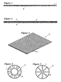
- FIG. 1 is a schematic cross-section illustrating a felt used in the present invention.
- FIG. 2 is a schematic cross-section showing another embodiment of a felt.
- FIG. 3 is a partial perspective enlarged view showing an example of a thin membrane film that can be cut with a micro-slitter.
- FIG. 4 is an enlarged end elevation showing an example of a dividable hollow composite fiber.
- FIG. 5 is an enlarged end elevation showing an example of a dividable radial composite fiber.
- FIG. 6 is a perspective view of an oiled belt showing an embodiment of a material for removing toner.
- FIG. 7 is a partial sectional view of an oiled roller showing another embodiment of a material for removing toner.
- FIG. 8 is a schematic side view illustrating the installation of the oiled roller shown in FIG. 7 .
- a felt 1 used for a material for removing residue toner according to the present invention, it is manufactured from carded lap made out of a heat-resistant organic fiber 2 produced by a film-splitting method or a fiber-dividing method.
- the carded lap is milled by needle-punching to obtain the felt 1 having a predetermined thickness and density by heat treatment.
- a high-pressure water-jet treatment or a resin finishing with a fluorocarbon resin such as FEP (tetrafluoroethylene hexafluoropropylene copolymer) resin may be carried out after the needle-punching, this resin finishing being, for instance, a surface-coating or impregnating treatment.
- a ground fabric 4 of a heat-resistant organic fiber may be put between bisecting carded laps 3 and 3 as shown in FIG. 2 or under single carded lap.
- the heat-resistant organic fiber 2 composing the felt is preferably a PTFE fiber or other fluorine fibers, a polyimide fiber and/or an aramid fiber which manufactured by a film-splitting method, especially preferably a PTFE fiber. It is possible to add at least one heat-resistant organic fiber manufactured by a dividing method and other inorganic or organic fibers and to blend it with the heat-resistant fiber 2 to such an extent that physical properties of the heat-resistant fiber 2 is not degraded. The mixture amount thereof is generally less than 50%.
- the felt 1 composed of these fibers is excellent in a thermal stability, an oil-retentivity, a cleaning property and the like.
- a thin membrane 5 manufactured by a melt membrane-making method or the like is cut into fibers with a micro slitter, the fibers being drawn and treated with heating according to circumstances, to obtain the organic fiber 2 whose cross section is rectangular in shape.
- PTFE fiber PTFE paste in which a supplementary agent such as petroleum agent is added to PTFE resin particulates is formed into a rawish tape-shaped membrane 5 with an extrusion-molding machine.
- the thin membrane 5 is cut into fibers with a micro slitter and then the fibers are drawn and treated with heating.
- the cross section of the PTFE fiber thus obtained is rectangular in shape.
- the organic fiber 2 produced by the film-splitting method has the form of an ultra fine tape, fineness thereof is more than 1 decitex and cross section thereof has an acute angle.
- the PTFE fiber produced by the film-splitting method is a white color as compared with brown fibers produced by an emulsion-spinning method.
- the additional fiber manufactured by the fiber-dividing method is a composite fiber 6 ( FIG. 4 and FIG. 5 ) of multi-component that consists of at least two and more fiber-forming resins of non-compatibility before dividing. Two and more resins are formed and integrated into a given shape of a raw fiber through a guide or passage in a nozzle plate and the raw fiber is extruded from the spinning nozzle, solidified and then wound up to obtain the composite fiber 6 .
- the composite fiber 6 is, for instance, a binary hollow fiber ( FIG. 4 ) or radial-shaped fiber ( FIG. 5 ) having one thermoplastic resin portion 7 of polyester and another thermoplastic resin portion 8 of nylon. The thermoplastic resin portions 7 , 8 turn into mixed heat-resistant fibers of polyester and nylon by dividing.
- a polyester/nylon fiber, a polyester/polypropylene fiber, a polyester/polyethylene/polypropylene fiber or a polyester/nylon/polypropylene fiber may be exemplified as a combination with thermoplastic resin portions 7 and 8 .
- the polyester/nylon fiber is suitable for the composite fiber 6 .
- one or more optional combinations can be adopted.
- the composite fiber 6 is dividable by a mechanical process such as needle-punching, a heating process or the chemical treatment with the solvent. As a result of this treatment, the composite fiber 6 is divided into fibers along given longitudinal contact lines to get 8, 16, 24 or more pieces of fiber. Fineness per a piece of the fibers after dividing is preferably 0.1-0.5 decitex.
- the divided fiber may be so formed that a cross section thereof has an acute angle, for example, the cross section thereof being not only like a sector in shape as shown in FIG. 4 , but also a nearly triangular in shape as shown in FIG. 5 .
- the felt 1 may be composed mainly of one or more heat-resistant divided fibers and may include partially one or more conventional divided fibers.
- conventional divided fibers are partially included, it is preferably to mount the material of the present invention on a relatively low temperature location inside a fixing machine, or to dispose the material of the present invention for a developing machine or the like in the lower temperature surroundings than the inside of the fixing machine with respect to a photographic imaging process.
- the felt composed of one or more divided fibers is excellent in oil retentivity and cleaning property. It is also possible to improve dimensional stability of the felt 1 better than ever by putting a ground fabric 4 ( FIG. 2 ).
- the material of the present invention may be mounted on a location where the felt 1 comes into contact with the surface of an operating member such as the fixing roller, a transferring roller or a developing roller or may be arranged around the operating member whose inside temperature reaches 220-230° C. during starting in the photographic imaging process.
- the material of the present invention may be applied to an acting member such as an oiled belt 11 ( FIG. 6 ), oiled roller 12 ( FIG. 7 ) or the like, in which silicone or fluorocarbon oil is impregnated in the predetermined volume before or after the installation of the felt 1 .
- the material of the present invention may be also used as the cleaning roller 14 ( FIG. 8 ) or the cleaning pad 15 ( FIG. 9 ) inside the fixing or developing machine.
- a PTFE fiber was manufactured by a film-splitting method, the fiber having a rectangular cross section and average fineness of 3.3 decitex.
- a web was made out of 100% these PTFE fibers. The web was accumulated to form carded lap having unit weight of 400 gm/m 2 and then punch the entire carded lap with needle. After punching with needle, it was pressed at about 250° C. for three minutes to obtain the felt 1 having 1.0 mm. in thickness.
- the felt 1 was used for an oiled belt 11 as shown in FIG. 6 .
- a couple of core rollers 16 , 16 made from aluminum or bakelite was horizontally disposed at regular intervals. Both the side edges of the felt 1 were put into contact with on the upper circumference of the core rollers 16 , 16 and then bonded with liquid epoxy resin.
- the felt 1 was kept horizontally by both of the core rollers 16 , 16 .
- a limit bar 18 was a plate having a long rectangular form.
- the limit bar 18 made from Duracon or epoxy resin was put into contact with on the surface of the felt 1 and then bonded with liquid epoxy resin.
- the limit bar 18 was arranged in parallel to a core roller 16 .
- silicone oil was impregnated into the felt 1 .
- the impregnation volume of silicone oil was 0.2 cc/cc.
- An oiled belt 11 was disposed so as to bring the felt 1 into contact with the circumference of a fixing roller in a fixing machine whose inside temperature reaches 220-230° C. during starting.
- the oiled belt 11 was sufficient for a toner-removing property.
- a slipping property, an oil-retention and oil-supply capacities thereof were also excellent.
- a FEP film 5 of 12.5 microns in thickness ( FIG. 3 ) manufactured by a melt membrane-making method was cut into fibers with a micro-slitter and then drawn to obtain FEP fibers having average fineness of 20 decitex whose cross section is rectangular in shape.
- Carded lap of unit weight of 400 gm/m 2 was made out of 100% these fibers and then the entire carded lap was punched with needle. After punching with needle, it was pressed at about 230° C. for three minutes to obtain the felt 1 having 1.5 mm. in thickness.
- Silicone oil was impregnated into the felt 1 to use for an oiled belt 11 as well as Example 1.
- the impregnation volume of silicone oil was 0.2 cc/cc.
- the oiled belt 11 was disposed so as to bring the felt 1 into contact with the circumference of a fixing roller in a fixing machine whose inside temperature reaches 220-230° C. during starting.
- the oiled belt 11 was sufficient for a toner-removing property. An oil-retention and oil-supply capacities thereof were also excellent.
- a PTFE fiber produced by an emulsion-spinning method had round cross section. 100% these fibers were uniformly carded or blended together to manufacture a web. This web received the same treatment as Example 1 to obtain a felt of 1.5 mm. in thickness and unit weight of 400 gm/m 2 .
- the felt thus obtained was applied to an oiled belt as well as Example 1. Silicone oil was impregnated into the felt. The impregnation volume of silicone oil was 0.2 cc/cc. This oiled belt was relatively good for a slipping property and oil-retention capacity, but was insufficient for a toner-removing property.
- the oiled roller 12 was arranged so as to bring the felt 1 into contact with the circumference of a fixing roller 22 in a fixing machine 21 whose inside temperature reaches 220-230° C. during starting.
- the oiled roller 12 was sufficient for a toner-removing property. An oil-retention property and oil-supply capacity thereof were also excellent.
- a cleaning roller 14 ( FIG. 8 ) was manufactured as well as Example 3 by means of a felt 1 of 1.0 mm. in thickness. In this case, oil was not impregnated into the roller. The cleaning roller 14 was sufficient for a toner-removing property when it was disposed so as to bring the felt 1 into contact with the circumference of a fixing roller 22 .
- the felt 1 manufactured in Example 1 was cut out to a width of 7 mm. and a length of 23 mm. and applied to a cleaning pad 15 .
- a base 24 of the cleaning pad 15 was made of phenol resin.
- a duplicated acrylic tape was put between the pad base 15 and the felt 1 to bond them together.
- 0.3 cc/cc of silicone oil was impregnated into the felt 1 .
- the size of the felt used for the cleaning pad 15 may be the range of 5-10 mm. in width and 20-30 mm. in length.
- the cleaning pad 15 was arranged so as to bring the felt 1 into contact with the circumference of a fixing roller in a fixing machine whose inside temperature reaches 220-230° C. during starting.
- the cleaning pad 15 was sufficient for a toner-removing property.
Abstract
Description
Claims (8)
Applications Claiming Priority (3)
| Application Number | Priority Date | Filing Date | Title |
|---|---|---|---|
| JP2005-002332U | 2005-04-15 | ||
| JPJP2005-002332U | 2005-04-15 | ||
| JP2005002332U JP3111895U (en) | 2005-04-15 | 2005-04-15 | Toner scraping material |
Publications (2)
| Publication Number | Publication Date |
|---|---|
| US20060233574A1 US20060233574A1 (en) | 2006-10-19 |
| US8050606B2 true US8050606B2 (en) | 2011-11-01 |
Family
ID=37108599
Family Applications (1)
| Application Number | Title | Priority Date | Filing Date |
|---|---|---|---|
| US11/398,871 Expired - Fee Related US8050606B2 (en) | 2005-04-15 | 2006-04-06 | Material for removing residue toner |
Country Status (2)
| Country | Link |
|---|---|
| US (1) | US8050606B2 (en) |
| JP (1) | JP3111895U (en) |
Cited By (1)
| Publication number | Priority date | Publication date | Assignee | Title |
|---|---|---|---|---|
| US9639036B2 (en) * | 2014-04-24 | 2017-05-02 | Canon Kabushiki Kaisha | Image heating apparatus having a rubbing rotatable member |
Families Citing this family (2)
| Publication number | Priority date | Publication date | Assignee | Title |
|---|---|---|---|---|
| US20050118073A1 (en) * | 2003-11-26 | 2005-06-02 | Fluidigm Corporation | Devices and methods for holding microfluidic devices |
| JP4689370B2 (en) * | 2005-06-30 | 2011-05-25 | 株式会社リコー | Fixing apparatus and image forming apparatus |
Citations (5)
| Publication number | Priority date | Publication date | Assignee | Title |
|---|---|---|---|---|
| US5576815A (en) * | 1995-09-29 | 1996-11-19 | Minnesota Mining And Manufacturing Company | Development apparatus for a liquid electrographic imaging system |
| US5649130A (en) * | 1995-08-11 | 1997-07-15 | Japan Vilene Company, Ltd. | Cleaning sheet, a cleaning member and a cleaning apparatus for a fuser roll |
| JPH10116011A (en) | 1996-08-22 | 1998-05-06 | Ricoh Co Ltd | Toner cleaning method |
| US6156681A (en) * | 1996-01-16 | 2000-12-05 | Daikin Industries, Ltd. | Multi layered felt, member formed of same, and method of manufacturing same |
| JP2001312172A (en) | 2000-04-28 | 2001-11-09 | Fujikoo:Kk | Felt material used in member on periphery of fixing device |
-
2005
- 2005-04-15 JP JP2005002332U patent/JP3111895U/en not_active Ceased
-
2006
- 2006-04-06 US US11/398,871 patent/US8050606B2/en not_active Expired - Fee Related
Patent Citations (5)
| Publication number | Priority date | Publication date | Assignee | Title |
|---|---|---|---|---|
| US5649130A (en) * | 1995-08-11 | 1997-07-15 | Japan Vilene Company, Ltd. | Cleaning sheet, a cleaning member and a cleaning apparatus for a fuser roll |
| US5576815A (en) * | 1995-09-29 | 1996-11-19 | Minnesota Mining And Manufacturing Company | Development apparatus for a liquid electrographic imaging system |
| US6156681A (en) * | 1996-01-16 | 2000-12-05 | Daikin Industries, Ltd. | Multi layered felt, member formed of same, and method of manufacturing same |
| JPH10116011A (en) | 1996-08-22 | 1998-05-06 | Ricoh Co Ltd | Toner cleaning method |
| JP2001312172A (en) | 2000-04-28 | 2001-11-09 | Fujikoo:Kk | Felt material used in member on periphery of fixing device |
Non-Patent Citations (1)
| Title |
|---|
| Machine translation of JP 2001-312172A. * |
Cited By (1)
| Publication number | Priority date | Publication date | Assignee | Title |
|---|---|---|---|---|
| US9639036B2 (en) * | 2014-04-24 | 2017-05-02 | Canon Kabushiki Kaisha | Image heating apparatus having a rubbing rotatable member |
Also Published As
| Publication number | Publication date |
|---|---|
| US20060233574A1 (en) | 2006-10-19 |
| JP3111895U (en) | 2005-07-28 |
Similar Documents
| Publication | Publication Date | Title |
|---|---|---|
| US5649130A (en) | Cleaning sheet, a cleaning member and a cleaning apparatus for a fuser roll | |
| EP0816946B1 (en) | Cleaning brush with electrically conductive fibers | |
| US5800908A (en) | Oil delivery sheet material for use in various printer devices | |
| US8050606B2 (en) | Material for removing residue toner | |
| US5877098A (en) | Abrasive sheet made of very fine and ultrafine fibers | |
| EP0969334A2 (en) | Oil coating apparatus | |
| JP5839114B2 (en) | Stampable seat | |
| JP7035336B2 (en) | Sliding member, sliding member for fixing device, fixing device and image forming device | |
| CN1289753C (en) | Dehydroating doctor | |
| JP3112862U (en) | Toner seal material | |
| JP2000161406A (en) | Wet type friction material | |
| JP2008173759A (en) | Abrasive cloth and its manufacturing method | |
| JP4695660B2 (en) | Toner scraping material | |
| JP6587448B2 (en) | Fixing tool and manufacturing method thereof | |
| JP2022033173A (en) | Slide member, slide member for fixing device, fixing device, and image forming apparatus | |
| JP4480849B2 (en) | Felt material used in fixing devices | |
| JP2006317647A (en) | Felt material for photographic image forming process | |
| JPH0744053A (en) | Cleaning material | |
| JP6647446B1 (en) | Toner seal material | |
| JP3263465B2 (en) | Cleaning sheet for copier | |
| JPS58199371A (en) | Cleaning web | |
| US6969691B2 (en) | Doctor blade for removing water | |
| JPH06167902A (en) | Cleaning web for fixing roll and cleaning device as well as cleaning method for fixing roll | |
| JP5040260B2 (en) | Abrasive cloth and method for producing the same | |
| CN114653137A (en) | Anti-oxidation glass fiber needled felt |
Legal Events
| Date | Code | Title | Description |
|---|---|---|---|
| AS | Assignment |
Owner name: FUJI CORPORATION, JAPAN Free format text: ASSIGNMENT OF ASSIGNORS INTEREST;ASSIGNOR:INADA, KAZUHIDE;REEL/FRAME:017772/0145 Effective date: 20060303 |
|
| ZAAA | Notice of allowance and fees due |
Free format text: ORIGINAL CODE: NOA |
|
| ZAAB | Notice of allowance mailed |
Free format text: ORIGINAL CODE: MN/=. |
|
| STCF | Information on status: patent grant |
Free format text: PATENTED CASE |
|
| FPAY | Fee payment |
Year of fee payment: 4 |
|
| MAFP | Maintenance fee payment |
Free format text: PAYMENT OF MAINTENANCE FEE, 8TH YR, SMALL ENTITY (ORIGINAL EVENT CODE: M2552); ENTITY STATUS OF PATENT OWNER: SMALL ENTITY Year of fee payment: 8 |
|
| FEPP | Fee payment procedure |
Free format text: MAINTENANCE FEE REMINDER MAILED (ORIGINAL EVENT CODE: REM.); ENTITY STATUS OF PATENT OWNER: SMALL ENTITY |
|
| LAPS | Lapse for failure to pay maintenance fees |
Free format text: PATENT EXPIRED FOR FAILURE TO PAY MAINTENANCE FEES (ORIGINAL EVENT CODE: EXP.); ENTITY STATUS OF PATENT OWNER: SMALL ENTITY |
|
| STCH | Information on status: patent discontinuation |
Free format text: PATENT EXPIRED DUE TO NONPAYMENT OF MAINTENANCE FEES UNDER 37 CFR 1.362 |
|
| FP | Lapsed due to failure to pay maintenance fee |
Effective date: 20231101 |