US8050199B2 - Endpoint registration with local back-off in a call processing system - Google Patents
Endpoint registration with local back-off in a call processing system Download PDFInfo
- Publication number
- US8050199B2 US8050199B2 US10/940,464 US94046404A US8050199B2 US 8050199 B2 US8050199 B2 US 8050199B2 US 94046404 A US94046404 A US 94046404A US 8050199 B2 US8050199 B2 US 8050199B2
- Authority
- US
- United States
- Prior art keywords
- endpoint
- message
- server
- processing system
- call processing
- Prior art date
- Legal status (The legal status is an assumption and is not a legal conclusion. Google has not performed a legal analysis and makes no representation as to the accuracy of the status listed.)
- Expired - Fee Related, expires
Links
- 238000012545 processing Methods 0.000 title claims abstract description 75
- 238000000034 method Methods 0.000 claims abstract description 64
- 230000008569 process Effects 0.000 claims abstract description 26
- 238000001514 detection method Methods 0.000 claims description 13
- 238000013459 approach Methods 0.000 abstract description 12
- 230000002776 aggregation Effects 0.000 abstract description 10
- 238000004220 aggregation Methods 0.000 abstract description 10
- 238000004891 communication Methods 0.000 description 20
- 238000010586 diagram Methods 0.000 description 13
- 238000011084 recovery Methods 0.000 description 13
- 230000000694 effects Effects 0.000 description 10
- 230000008901 benefit Effects 0.000 description 9
- 230000006870 function Effects 0.000 description 9
- 238000002474 experimental method Methods 0.000 description 5
- 238000004088 simulation Methods 0.000 description 5
- QYSGYZVSCZSLHT-UHFFFAOYSA-N octafluoropropane Chemical compound FC(F)(F)C(F)(F)C(F)(F)F QYSGYZVSCZSLHT-UHFFFAOYSA-N 0.000 description 4
- 230000011664 signaling Effects 0.000 description 4
- 230000006399 behavior Effects 0.000 description 3
- 230000009286 beneficial effect Effects 0.000 description 3
- 230000000295 complement effect Effects 0.000 description 3
- 230000000977 initiatory effect Effects 0.000 description 3
- 230000007246 mechanism Effects 0.000 description 3
- 230000004931 aggregating effect Effects 0.000 description 2
- 230000007423 decrease Effects 0.000 description 2
- 239000004744 fabric Substances 0.000 description 2
- 230000006872 improvement Effects 0.000 description 2
- 230000009467 reduction Effects 0.000 description 2
- 238000012546 transfer Methods 0.000 description 2
- 230000003466 anti-cipated effect Effects 0.000 description 1
- 230000005540 biological transmission Effects 0.000 description 1
- 230000015556 catabolic process Effects 0.000 description 1
- 230000001186 cumulative effect Effects 0.000 description 1
- 238000006731 degradation reaction Methods 0.000 description 1
- 230000002708 enhancing effect Effects 0.000 description 1
- 208000015181 infectious disease Diseases 0.000 description 1
- 230000010354 integration Effects 0.000 description 1
- 238000007726 management method Methods 0.000 description 1
Images


Classifications
-
- H—ELECTRICITY
- H04—ELECTRIC COMMUNICATION TECHNIQUE
- H04L—TRANSMISSION OF DIGITAL INFORMATION, e.g. TELEGRAPHIC COMMUNICATION
- H04L67/00—Network arrangements or protocols for supporting network services or applications
- H04L67/01—Protocols
- H04L67/10—Protocols in which an application is distributed across nodes in the network
- H04L67/1001—Protocols in which an application is distributed across nodes in the network for accessing one among a plurality of replicated servers
- H04L67/1034—Reaction to server failures by a load balancer
-
- H—ELECTRICITY
- H04—ELECTRIC COMMUNICATION TECHNIQUE
- H04L—TRANSMISSION OF DIGITAL INFORMATION, e.g. TELEGRAPHIC COMMUNICATION
- H04L65/00—Network arrangements, protocols or services for supporting real-time applications in data packet communication
- H04L65/1066—Session management
- H04L65/1073—Registration or de-registration
-
- H—ELECTRICITY
- H04—ELECTRIC COMMUNICATION TECHNIQUE
- H04L—TRANSMISSION OF DIGITAL INFORMATION, e.g. TELEGRAPHIC COMMUNICATION
- H04L67/00—Network arrangements or protocols for supporting network services or applications
- H04L67/01—Protocols
- H04L67/10—Protocols in which an application is distributed across nodes in the network
- H04L67/1001—Protocols in which an application is distributed across nodes in the network for accessing one among a plurality of replicated servers
- H04L67/1004—Server selection for load balancing
- H04L67/1019—Random or heuristic server selection
-
- H—ELECTRICITY
- H04—ELECTRIC COMMUNICATION TECHNIQUE
- H04L—TRANSMISSION OF DIGITAL INFORMATION, e.g. TELEGRAPHIC COMMUNICATION
- H04L69/00—Network arrangements, protocols or services independent of the application payload and not provided for in the other groups of this subclass
- H04L69/40—Network arrangements, protocols or services independent of the application payload and not provided for in the other groups of this subclass for recovering from a failure of a protocol instance or entity, e.g. service redundancy protocols, protocol state redundancy or protocol service redirection
-
- H—ELECTRICITY
- H04—ELECTRIC COMMUNICATION TECHNIQUE
- H04M—TELEPHONIC COMMUNICATION
- H04M3/00—Automatic or semi-automatic exchanges
- H04M3/42—Systems providing special services or facilities to subscribers
- H04M3/50—Centralised arrangements for answering calls; Centralised arrangements for recording messages for absent or busy subscribers ; Centralised arrangements for recording messages
- H04M3/51—Centralised call answering arrangements requiring operator intervention, e.g. call or contact centers for telemarketing
- H04M3/523—Centralised call answering arrangements requiring operator intervention, e.g. call or contact centers for telemarketing with call distribution or queueing
- H04M3/5237—Interconnection arrangements between ACD systems
-
- H—ELECTRICITY
- H04—ELECTRIC COMMUNICATION TECHNIQUE
- H04M—TELEPHONIC COMMUNICATION
- H04M3/00—Automatic or semi-automatic exchanges
- H04M3/08—Indicating faults in circuits or apparatus
- H04M3/12—Marking faulty circuits "busy"; Enabling equipment to disengage itself from faulty circuits ; Using redundant circuits; Response of a circuit, apparatus or system to an error
-
- H—ELECTRICITY
- H04—ELECTRIC COMMUNICATION TECHNIQUE
- H04M—TELEPHONIC COMMUNICATION
- H04M3/00—Automatic or semi-automatic exchanges
- H04M3/42—Systems providing special services or facilities to subscribers
- H04M3/50—Centralised arrangements for answering calls; Centralised arrangements for recording messages for absent or busy subscribers ; Centralised arrangements for recording messages
- H04M3/51—Centralised call answering arrangements requiring operator intervention, e.g. call or contact centers for telemarketing
- H04M3/523—Centralised call answering arrangements requiring operator intervention, e.g. call or contact centers for telemarketing with call distribution or queueing
- H04M3/5232—Call distribution algorithms
- H04M3/5234—Uniform load distribution
Definitions
- the invention relates generally to call centers or other call processing systems in which voice calls, e-mails, faxes, voice messages, text messages, Internet service requests or other types of communications are distributed among a number of service agents for handling, and more particularly to call centers which include multiple geographically-distributed work sites.
- Call centers distribute calls and other types of communications or work items to available service agents in accordance with various predetermined criteria.
- a given call center may be implemented in a geographically distributed manner, e.g., as a combination of multiple distributed call center sites at different locations. Such an arrangement is commonly referred to as a multi-site call center or more generally a multi-site call processing system.
- a centralized load balancing process is typically utilized in order to distribute communications among the various sites for processing.
- an important cause of instability in a given multi-site call processing system relates to an overload situation as endpoints attempt to register after a network failure, equipment shutdown or other similar condition. Techniques are needed which can provide improved performance in these and other situations.
- the present invention provides dependability enhancement techniques suitable for implementation in a multi-site call processing system or other type of call processing system.
- a call processing system which may include multiple distributed call center sites, utilizes a local back-off approach to endpoint registration.
- the call processing system comprises a plurality of endpoints and at least a first server, wherein the endpoints register with the first server in order to send and receive calls in the call processing system.
- Responsive to an end-to-end connectivity failure or other designated event a registration process is initiated in the call processing system for a given one of the endpoints.
- the issuance of at least one message of the sequence for the given endpoint is controlled so as to provide a local random back-off or other local back-off of the controlled message at that endpoint.
- a second server implemented as an aggregation server is configured to control the issuance of messages by the endpoints, so as to provide a local random back-off for each of the plurality of endpoints, by staggering the delivery of failure notifications to the endpoints.
- the invention in the illustrative embodiment considerably alleviates the above-described overload situation that could otherwise result as endpoints attempt to register after a network failure, equipment shutdown or other similar condition.
- FIG. 1 is a block diagram of an exemplary multi-site call processing system in which the invention may be implemented.
- FIG. 2 is a block diagram of one possible implementation of a distributed call center in the multi-site call processing system of FIG. 1 .
- FIG. 3 is a timing diagram showing a successful registration sequence for an endpoint of the FIG. 1 system.
- FIG. 4 is a timing diagram showing a bottleneck that may arise when a large number of endpoints make substantially simultaneous registration attempts in the FIG. 1 system.
- FIG. 5 is a timing diagram showing the use of local random back-off before registration initiation in accordance with an illustrative embodiment of the invention.
- FIG. 6 is a block diagram of one possible implementation of at least a portion of the FIG. 1 system, comprising an aggregation server (AS) in accordance with an illustrative embodiment of the invention.
- AS aggregation server
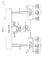
- FIG. 7 is a timing diagram illustrating the operation of the AS of FIG. 6 .
- FIGS. 8 through 12 are plots showing various performance aspects of illustrative embodiments of the invention.
- a call center in accordance with the invention may be configured using any type of network infrastructure, such as, e.g., asynchronous transfer mode (ATM), local area networks, wide area networks, Internet Protocol (IP) networks, etc.
- ATM asynchronous transfer mode
- IP Internet Protocol
- call center as used herein is thus intended to include any type of ACD system, telemarketing system or other communication system which processes calls or other service requests, including voice calls, video calls, multimedia calls, e-mail, faxes, text chat or voice messages as well as various portions or combinations of these and other types of communications.
- call as used herein is intended to include any of the above-noted types of communications as well as portions or combinations of these and other communications.
- FIG. 1 shows an illustrative call processing system 10 including multiple distributed call center sites.
- the system 10 includes a network provider 20 , a central load balancing application 30 , and a set of performance data 40 .
- the network provider 20 is coupled via sets of trunks 50 and 60 to distributed call center sites 100 - 1 and 100 - 2 , respectively.
- the invention can be implemented in a system having any desired number of sites. Also, as indicated previously, the invention can be implemented in a single-site call processing system.
- At least a subset of the agent terminals 110 may be separated from the call center sites 100 via one or more service provider networks (not shown).
- Such a configuration is desirable in applications in which the agent terminals need to be geographically distributed, but the call center sites or one or more associated servers need to be located at a single location for the sake of maintainability, security or privacy. Numerous other configurations are possible, as will be appreciated by those skilled in the art.
- the agent terminals 110 may be viewed as examples of what are more generally referred to herein as endpoints. Such endpoints may include, by way of example, IP telephones or other types of telephones, computer terminals, workstations, etc.
- Each of the call center sites 100 - 1 and 100 - 2 may include, in addition to other elements, one or more servers, as will be described in greater detail below.
- Endpoints typically register with a corresponding server of the call center site, as is well known.
- central load balancing application 30 receives notification of an incoming call from the network provider 20 .
- the central load balancing application 30 then accesses the performance data 40 in order to determine where to route the call, i.e., which of the distributed call center sites 100 - i should receive the call.
- the central load balancing application 30 notifies the network provider 20 of its call center site selection, and the network provider 20 accordingly routes the incoming call to the selected one of the distributed call center sites 100 - i over the appropriate trunk.
- conventional agent selection and call selection techniques may be used to direct the incoming call to a particular agent terminal in the corresponding set of agent terminals 10 - i . This process is repeated for all incoming calls directed to the multi-site call processing system 10 .
- Performance data is collected from the distributed call center sites 100 - i and stored in the set of performance data 40 for use by the load balancing application 30 in making future call routing decisions.
- FIG. 2 shows a simplified block diagram of one possible implementation of a given one of the distributed call center sites 100 - i in the system 10 of FIG. 1 .
- the distributed call center site 100 - i comprises interfaces 112 to external communication links, a communications switch fabric 113 , and service circuits 114 which may be, e.g., tone generators, announcement circuits, etc.
- the distributed call center site 100 - i further includes a memory 115 and a processor 116 .
- the memory 115 may be used for storing, e.g., control programs, data, etc., and may be an electronic memory, a disk-based memory or a combination of these and other memory elements.
- the processor 116 is configured to execute stored control programs to control the interfaces 112 and the switch fabric 113 , to provide call distribution functionality, and to provide storage or processing of e-mails, faxes and other communications.
- the processor 116 may be, e.g., a microprocessor, a central processing unit (CPU), a computer, an application-specific integrated circuit (ASIC), or various portions or combinations of these and other processing elements.
- the distributed call center site 100 - i of FIG. 1 may comprise a communication system switch, such as a DEFINITY® Enterprise Communication Service (ECS) communication system switch available from Avaya Inc. of Basking Ridge, N.J., USA.
- ECS DEFINITY® Enterprise Communication Service
- MV MultiVantageTM
- Such devices may be viewed as comprising examples of what are more generally referred to herein as servers.
- One or more servers, or portions or combinations thereof, may be implemented, by way of example, utilizing the memory 115 and processor 116 .
- an example embodiment of a given call center site may include multiple servers, such as an MV server, a Dynamic Host Configuration Protocol (DHCP) server, and a Trivial File Transfer Protocol (TFTP) server.
- MV server a Dynamic Host Configuration Protocol
- TFTP Trivial File Transfer Protocol
- Such servers may be implemented within a system switch, or external to such a switch.
- a given switch may be viewed as comprising one or more servers.
- FIGS. 1 and 2 are by way of example only, and should not be construed as limiting the invention to any particular embodiment or group of embodiments.
- the invention can be implemented in many other types of multi-site processing system configurations, such as those described in U.S. Pat. No. 5,754,639 issued May 19, 1998 in the name of inventors A. D. Flockhart et al. and entitled “Method and Apparatus for Queuing a Call to the Best Split,” which is incorporated by reference herein.
- FIGS. 1 and 2 may be programmed or otherwise configured in a straightforward manner to implement the dependability enhancement techniques of the present invention as described below.
- an important cause of instability in a system such as that described above relates to an overload situation as endpoints attempt to register after a network failure, equipment shutdown or other similar condition.
- the term “register” in this context is intended to include a process which enables IP endpoints or other endpoints to make themselves known to a server so that they can place and receive calls in the system.
- the registration process may involve the binding of IP addresses for the endpoints to particular system extensions.
- the process of failure detection and registration in conventional systems is typically accomplished via message exchanges which are specified in the ITU-T recommendations, including ITU-T Recommendation H.323, “Packet based multimedia communication systems,” 1998, and ITU-T Recommendation H.245, “Control protocol for multimedia communication,” 1998, both of which are incorporated by reference herein.
- TCP Transmission Control Protocol
- a connectivity failure may be assumed to have occurred.
- the exact determination of failure is usually not based on a single timeout, but a sequence of keep-alive timeouts.
- the recovery process starts, which may include the discovery of the server and/or an associated Avaya control local area network (CLAN) board or other device, followed by registration of the endpoint with that server.
- the discovery procedure involves GRQ/GCF messages, whereas the registration involves RRQ/RCF messages.
- GRQ and GCF denote Gateway Request and Gateway Confirm, respectively
- RRQ and RCF denote Registration Request and Registration Confirm, respectively.
- the GRQ/GCF and RRQ/RCF messages may be collectively viewed as one particular example of what is more generally referred to herein as a “registration sequence.”
- a network outage at a given call center site may cause recovery initiation by as many as 1000 or more IP phones or other endpoints within a short duration.
- the flood of GRQ messages causes the associated server to be overloaded.
- the net result of overload is loss of GRQs, which leads to multiple registration retries by a large subset of the endpoints. Some may eventually go into a reboot mode.
- the overload occurs since the server is typically limited to processing only a certain number of simultaneous registration sequences, such as 10.
- a typical IP endpoint exchanges a User Datagram Protocol (UDP) message sequence with the server in order to register itself.
- UDP User Datagram Protocol
- the total time taken for these steps is what we shall call the registration time Treg.
- the time and message exchange sequence is depicted in FIG. 3 .
- an RRQ message is not received at the server within a specified time, e.g., within 15 seconds of it sending a GCF message to the endpoint, then the server releases the registration. It will be assumed that, due to limitations of its associated login manager elements, the server can only process 10 simultaneous registrations (although other embodiments may use login manager elements able to handle more or fewer simultaneous registrations). In other words, if at any time 10 registration procedures are underway, then no more GRQs can be processed at that time. If x GRQs arrive at the server within a registration time period, where x is greater than 10, then x-10 requests are dropped.
- WAN wide area network
- the first one is rate throttling of GRQs and the second one is the use of Registration-in-Progress (RIP) messages.
- RIP Registration-in-Progress
- Rate Throttling of GRQs The notion is to throttle the flood of GRQs before they reach the server.
- One of the elements which allows throttling is a gateway router at the call center site. In a typical deployment, the router may be configured to rate limit the GRQ requests to a value at or below the rate the server can handle, which may be approximately 100 GRQs per second.
- RIP messages Since the server in the present example can only process 10 simultaneous registration sequences, in the case of a GRQ flood, a substantial number of endpoints time out waiting for GCF and start to retry with GRQs, thereby worsening the flood.
- the server sends out a RIP message to the endpoint before dropping the GRQ, requesting it to retry after a timeout interval specified in the RIP message. This timeout is normally larger than the local timeout at the endpoint, resulting in slowing down of GRQs arriving at the server.
- rate throttling and RIP messaging shall be assumed in the description of the illustrative embodiment unless noted otherwise.
- the registering endpoints comprise IP endpoints, although the techniques are also applicable to a wide variety of other types of endpoints. It should be appreciated, however, that these and other assumptions referred to herein need not apply in alternative embodiments of the invention.
- rate throttling and RIP messaging solutions are supplemented through the use of an approach referred to herein as local random back-off by endpoints.
- FIG. 4 illustrates a situation in which multiple substantially simultaneous registration attempts are made in the FIG. 1 system.
- time is shown on the horizontal axis.
- Events from typical IP endpoints are depicted as symbols with legends. It should be noted that RRQ messages are not shown for clarity and simplicity of illustration.
- the GRQs are generated at the endpoints and are received at the server within a short span. While the first 10 GRQs grab available login manager elements at the server and engage in the registration sequence, any subsequent arrivals receive a RIP message back. Note however, that the following conditions still hold true:
- GRQs are queued at the server and are examined in a first-in first-out (FIFO) manner.
- Sending a RIP message consumes server processor resources.
- the RIP messaging solution works on the principle of “tolerating” the GRQ flood once it starts to occur.
- the local random back-off approach of the present invention is complementary to RIP as it aims to prevent the occurrence of the GRQ flood to begin with.
- the timing diagram of FIG. 5 illustrates one implementation of the random back-off approach.
- TCP keep-alive messages from the CLAN to the IP endpoint (with timeouts and retries) is construed as a failure of end-to-end connectivity. Missing RAS keep-alive messages, where appropriate, may also be used to detect failures.
- an IP endpoint detects a failure, it starts the re-registration process by sending out a GRQ message to the CLAN in its list.
- the IP endpoint performs a random back-off after failure detection and before the GRQ is sent.
- the range of the random numbers is determined by factors such as the total number of IP endpoints, the platform (e.g., Avaya DEFINITY® G3r, Avaya DEFINITY® S8700, etc.) and preferably should be preconfigured.
- the platform e.g., Avaya DEFINITY® G3r, Avaya DEFINITY® S8700, etc.
- the registration initiation gets staggered because of the back-off.
- Generating RIP messages consumes CPU resources at the server.
- the use of local back-offs reduces the contention for CPU resources at the MV server and more CPU resources are then available for registration processing and call processing since the need for generating RIP messages is reduced.
- System/endpoint recovery is less susceptible to loss of RIP messages as there are fewer RIP messages to begin with. As indicated above, a RIP message from the server to the endpoint may be lost in network transit.
- GRQ messages are queued at various processes/components before finally being processed by the server. These include the CLAN interface and associated higher protocol processes, other processes at the server, etc. It is possible in a sudden burst of GRQs for some queue to overflow, resulting in the loss of a GRQ before it is processed.
- the local back-off at the endpoint substantially reduces the probability of queue overflow by controlling the GRQ rate at the source, i.e., the endpoint.
- the recovery state machine is more robust as there is less probability of the endpoint exhausting its retries on an available CLAN and therefore trying another one on the list. In some cases without RIP messaging in place, it was noted that phones went into a reboot cycle.
- the IP endpoints in the illustrative embodiment preferably are provided with an indication of an optimal back-off duration M opt .
- M opt an optimal back-off duration
- the MV server indicates the value of M opt to the endpoint. This value may be statically configured in the MV server by an administrator, or otherwise provided to the server.
- the endpoints can obtain the value of M opt from a DHCP server in one of the optional parameters.
- the DHCP server in turn, could be administered manually or otherwise with the value.
- an additional architectural element is introduced, which we refer to as the aggregation server (AS).
- AS aggregation server
- FIG. 6 illustrates an example of the placement of an AS in an example call center site, as well as its functionality.
- the AS in the figure is shown as a separate network element, this is not necessarily the case.
- some of the capabilities of the AS could be co-located with another system server, such as an MV server or a TFTP server.
- the set of system elements shown in FIG. 6 may be viewed as representing one possible implementation of at least a portion of the FIG. 1 multi-site call processing system, or of a single-site call processing system.
- RRJ in the figure denotes Registration Reject
- RAS Registration Admissions Signaling
- KA keep-alive
- a call processing system 200 comprises an Avaya DEFINITY® ECS switch 202 which in this embodiment includes as elements thereof an Avaya CLAN 204 and a software-based MV server 206 .
- the switch 202 is coupled via LAN 212 , router 214 , WAN 216 and router 218 to AS 210 .
- the AS 210 is coupled via LAN 220 to endpoints 222 .
- the AS 210 is coupled between the switch 202 and the endpoints 222 in this embodiment.
- the CLAN 204 in this embodiment serves as an IP interface to the MV server 206 .
- the CLAN receives GRQ messages and passes them to the MV server.
- the IP endpoints 222 typically connect to the MV server 206 over a WAN link.
- Functions such as failure detection, registration, call signaling and call data all traverse the WAN link with separate end-to-end connections between each endpoint and the server.
- each endpoint has its own TCP connection with the CLAN 204 over which TCP keep-alives are exchanged. Since the WAN link has a limited capacity which is shared for call signaling, call data and management traffic, any aggregation of traffic should free up the link for more calls.
- the AS 210 in this embodiment is placed at the call center site to serve as an aggregation point for many functions which are performed by the IP endpoints on an individual basis. Examples of these functions are listed below.
- the detection will first happen at the AS.
- the endpoints then may not be notified immediately of the failure upon which they will each start the re-registration procedure. Rather, the AS can stagger the notifications in time to each endpoint such that a GRQ flood is avoided.
- the AS can also serve as a registration proxy for all endpoints local to its site. This could be easily achieved, for example, by setting the IP address of the AS to the first address in a list of one or more server addresses that is sent to the endpoint or manually configured at the endpoint, or by use of DHCP. Such a feature may require the AS to have part of the H.323 stack. In the least, the NAT/PAT capability is needed if the AS were to serve as a pass-through proxy acting only at layer 3.
- the AS can deploy rate control mechanisms to control the rate of GRQs passing through to the MV server. As shown in the diagram of FIG. 6 , the rate control could be based on a token bucket scheme, in which the tokens are generated based the rate of RCF and GCG messages from the MV server to the endpoints.
- the AS can combine multiple GRQs into a single packet that is sent to the MV server. Although this results in network resource savings, the protocol between the AS and the server becomes non-standard. An approach in which this GRQ aggregation occurs only when the failure is known to be a catastrophic failure might also be beneficial.
- the simulation includes the endpoints, LANs, WAN, CLAN, MV server, DHCP server, and TFTP server.
- Each element has certain settable parameters (such as the amount of time needed to process each particular message type).
- Elements also maintain the state information needed to process protocols such as DHCP, TFTP, H323 RAS, etc.
- the simulator was able to predict the behavior of a system with the proposed enhancements. For example, the local random back-off approach was added to the simulator without having to implement the feature in actual endpoints.
- the sets of simulation trials that only varied the endpoint boot rate were grouped into runs. In each run, the endpoint boot rate was evaluated at rates of 5 ms, 10 ms, 20 ms, 40 ms, 75 ms, 100 ms, 150 ms, and 250 ms. Because one of the primary advantages of the back-off solution is that the MV process spends less time processing RIP messages, intuitively, the RIP message processing time should be a factor for the effectiveness of the strategy. The RIP message processing time was evaluated at 2.5 ms, 5 ms, and 15 ms.
- the simulation results may be graphed in any of a few ways.
- FIG. 8 graphs the number of endpoints registered (on the vertical axis) versus the time (on the horizontal axis). Each curve represents a different boot rate.
- FIG. 9 graph the simulated results to show the amount of time required to register the endpoints (on the vertical axis) as a function of the boot rate in milliseconds (on the horizontal axis). Data points for different boot rates in the same run are connected.
- FIG. 8 shows the cumulative number of endpoints registered as a function of time for various boot rates. Note that the first registration does not occur until after 30 seconds because the simulator includes the booting process on the IP endpoints (though, for these experiments, the endpoints were configured to bypass the DHCP and TFTP servers).
- the RIP message processing time was set to 10 ms for this graph. In general, the time required to register the endpoints decreases as the boot rate decreases until it passes an optimal value (near 150 ms). Beyond the optimal value, the server was idle while waiting for the endpoints to attempt to register.
- the curve is flat, because the server was always free to process the next request.
- the second slowest boot rate (150 ms) was slightly faster than the optimal rate. A few requests needed to be retried, resulting in an infection point for the last 40 or so endpoints.
- the curves for the fastest boot rates have an inflection point for the around 40 seconds before the first few endpoints registered. This suggests that the server was completely overwhelmed until after the RIP message processing has spaced out the requests. For example, it is likely that the GRQ messages were being dropped due to the limited length input queue on the server.
- the endpoints In the worst-case (10 ms boot rate), the endpoints required 360 seconds to register. The best-case (150 ms) required only 247 seconds. Setting the local random back-off rate to 150 seconds, the registration time could be reduced by 113 seconds from the worst case. Measuring from the time the first endpoint completes the boot process (i.e., ignoring the 25 second boot time before the first registration message was sent), the back-off approach improved the registration time by more than 1 ⁇ 3.
- FIG. 9 shows the effect of rate limiting at the WAN router.
- Rate limiting was only effective in certain situation: For example, with a boot rate of 40 ms and a RIP message processing time of 15 ms, rate-limiting improves the performance by 2.5% (from 401 to 391 seconds). In most other scenarios, rate-limiting had no noticeable effect on performance or led to a slight degradation.
- FIG. 10 shows the effect of 5% random packet loss.
- a high level of packet loss increased the time needed to complete the registration process because useful packets were dropped.
- What may be surprising, is how resilient the system was to packet loss. Note that the combination of packet loss and rate-limiting often performed worse than packet loss alone. In each case, the local back-off was still effective in reducing the completion time compared to the best-effort case.
- FIG. 11 shows the time to register 100%, 95%, and 90% of 2000 endpoints with three RIP message processing times.
- the described techniques may be applied to systems other than those comprising distributed call center sites.
- the techniques of the invention may be applied to a single-site system.
- FIG. 1 may be altered to incorporate a wide variety of different arrangements of components to provide the processing functions described herein.
- One such alternative arrangement may be configured such that the described techniques are implemented at least in part in a so-called “off-board” server, e.g., a server outside of a system switch.
- a server e.g., a server outside of a system switch.
- one or more servers control the distribution of work to agents in an enterprise, such that the processing functions related to distribution can be moved in whole or in part from the switch to the servers.
- the term “call center” as used herein is intended to include these and other alternative systems in which the present invention can be implemented.
- the local random back-off approach described above may be implemented using other types of local back-off, for example, back-off which is not necessarily random, but is instead pseudorandom or follows a particular predetermined pattern.
- the AS described above is merely an example of one type of proxy that may be used to provide the associated functionality, and other types of proxies, based on techniques other than the described token bucket technique, may be used.
- the invention may be implemented at least in part in the form of a computer-readable medium or other similar medium containing software which, when executed by a computer or other type of processor, will cause the processor to implement the processing functions described above.
- software programs may be stored in memory 115 or any other computer readable medium associated with the system 10 , and executed by processor 116 or other processing hardware associated with the system 10 .
Abstract
Description
Claims (19)
Priority Applications (4)
| Application Number | Priority Date | Filing Date | Title |
|---|---|---|---|
| US10/940,464 US8050199B2 (en) | 2003-09-30 | 2004-09-14 | Endpoint registration with local back-off in a call processing system |
| DE112004001819.6T DE112004001819B4 (en) | 2003-09-30 | 2004-09-30 | Endpoint registration with local delay time in a call processing system |
| GB0603998A GB2421145B (en) | 2003-09-30 | 2004-09-30 | Endpoint registration with local back-off in a call processing system |
| PCT/US2004/032496 WO2005033900A2 (en) | 2003-09-30 | 2004-09-30 | Endpoint registration with local back-off in a call processing system |
Applications Claiming Priority (2)
| Application Number | Priority Date | Filing Date | Title |
|---|---|---|---|
| US50717903P | 2003-09-30 | 2003-09-30 | |
| US10/940,464 US8050199B2 (en) | 2003-09-30 | 2004-09-14 | Endpoint registration with local back-off in a call processing system |
Publications (2)
| Publication Number | Publication Date |
|---|---|
| US20050068907A1 US20050068907A1 (en) | 2005-03-31 |
| US8050199B2 true US8050199B2 (en) | 2011-11-01 |
Family
ID=34381308
Family Applications (1)
| Application Number | Title | Priority Date | Filing Date |
|---|---|---|---|
| US10/940,464 Expired - Fee Related US8050199B2 (en) | 2003-09-30 | 2004-09-14 | Endpoint registration with local back-off in a call processing system |
Country Status (4)
| Country | Link |
|---|---|
| US (1) | US8050199B2 (en) |
| DE (1) | DE112004001819B4 (en) |
| GB (1) | GB2421145B (en) |
| WO (1) | WO2005033900A2 (en) |
Cited By (2)
| Publication number | Priority date | Publication date | Assignee | Title |
|---|---|---|---|---|
| US20180324640A1 (en) * | 2015-11-25 | 2018-11-08 | Hitachi Automotive Systems, Ltd. | Vehicle-Mounted Gateway Device, Electronic Control Device, and Vehicle-Mounted Network System |
| CN109314846A (en) * | 2016-05-04 | 2019-02-05 | 捷德移动安全有限责任公司 | Subscriber's self-activation equipment, program and method |
Families Citing this family (13)
| Publication number | Priority date | Publication date | Assignee | Title |
|---|---|---|---|---|
| US7860918B1 (en) | 2006-06-01 | 2010-12-28 | Avaya Inc. | Hierarchical fair scheduling algorithm in a distributed measurement system |
| US8767944B1 (en) | 2007-01-03 | 2014-07-01 | Avaya Inc. | Mechanism for status and control communication over SIP using CODEC tunneling |
| US7876690B1 (en) * | 2007-09-26 | 2011-01-25 | Avaya Inc. | Distributed measurement system configurator tool |
| US8116237B2 (en) * | 2008-09-26 | 2012-02-14 | Avaya Inc. | Clearing house for publish/subscribe of status data from distributed telecommunications systems |
| CN101883190A (en) * | 2009-05-06 | 2010-11-10 | 华为技术有限公司 | Seat processing method, switch and call center |
| CN101645800B (en) * | 2009-08-20 | 2011-09-21 | 中兴通讯股份有限公司 | Upgrading method and system of computer telecommunication integrated device |
| CA2796431C (en) * | 2010-04-15 | 2018-04-10 | Vonage Network, Llc | Systems and methods of improving the quality of voip communications |
| US8976949B2 (en) * | 2010-06-29 | 2015-03-10 | Telmate, Llc | Central call platform |
| CN104539558B (en) * | 2014-12-31 | 2018-09-25 | 林坚 | Extendible capacity IP phone interchanger rolling reamer machine system and automatic expansion method |
| KR102340796B1 (en) * | 2015-05-11 | 2021-12-17 | 삼성전자주식회사 | Method and terminal for communicating |
| US10142353B2 (en) | 2015-06-05 | 2018-11-27 | Cisco Technology, Inc. | System for monitoring and managing datacenters |
| US10536357B2 (en) | 2015-06-05 | 2020-01-14 | Cisco Technology, Inc. | Late data detection in data center |
| US20240095127A1 (en) * | 2022-06-07 | 2024-03-21 | Datto, Inc. | Fleetwide Adaptive Rate Limiting Gatekeeper Apparatuses, Processes and Systems |
Citations (23)
| Publication number | Priority date | Publication date | Assignee | Title |
|---|---|---|---|---|
| US5206903A (en) | 1990-12-26 | 1993-04-27 | At&T Bell Laboratories | Automatic call distribution based on matching required skills with agents skills |
| US5226077A (en) | 1992-03-02 | 1993-07-06 | Acs Communications, Inc. | Headset amplifier with automatic log on/log off detection |
| US5754639A (en) | 1995-11-03 | 1998-05-19 | Lucent Technologies | Method and apparatus for queuing a call to the best split |
| US5905793A (en) | 1997-03-07 | 1999-05-18 | Lucent Technologies Inc. | Waiting-call selection based on anticipated wait times |
| US5960001A (en) * | 1997-06-19 | 1999-09-28 | Siemens Information And Communication Networks, Inc. | Apparatus and method for guaranteeing isochronous data flow on a CSMA/CD network |
| EP1047241A2 (en) | 1999-04-22 | 2000-10-25 | Siemens Information and Communication Networks Inc. | System and method for restarting of signaling entities in H.323-based realtime communication networks |
| US6192122B1 (en) | 1998-02-12 | 2001-02-20 | Avaya Technology Corp. | Call center agent selection that optimizes call wait times |
| WO2001069862A2 (en) | 2000-03-16 | 2001-09-20 | Sri International | Mobile ad hoc extensions for the internet |
| US20020067822A1 (en) | 1998-12-23 | 2002-06-06 | Richard Allen Cohen | Call selection based on continuum skill levels in a call center |
| US20020101860A1 (en) * | 1999-11-10 | 2002-08-01 | Thornton Timothy R. | Application for a voice over IP (VoIP) telephony gateway and methods for use therein |
| US20030026241A1 (en) * | 2001-04-27 | 2003-02-06 | Hideaki Ono | Packet transfer method for hierarchical packet network, hierarchical packet communication system, and gate node, edge node and mobile terminal for use with hierarchical packet communication system, as well as handover method and routing node for packet network |
| US20030053480A1 (en) * | 2001-09-20 | 2003-03-20 | Kyung-Hun Jang | Data communications method using backoff number control |
| US6563920B1 (en) | 1999-12-15 | 2003-05-13 | Avaya Technology Corp. | Methods and apparatus for processing of communications in a call center based on variable rest period determinations |
| US20030123619A1 (en) | 2001-12-28 | 2003-07-03 | Mckinnon Steve J. | Voice authenticated terminal registration |
| US20030167343A1 (en) * | 2002-03-04 | 2003-09-04 | Takayuki Furuno | Communications system |
| US6633640B1 (en) | 2000-02-01 | 2003-10-14 | Avaya Technology Corp. | Methods and apparatus for analysis of load-balanced multi-site call processing systems |
| US6697858B1 (en) | 2000-08-14 | 2004-02-24 | Telephony@Work | Call center |
| US20040078338A1 (en) * | 2002-08-28 | 2004-04-22 | Yuusaku Ohta | Content duplication management system and networked apparatus |
| US6728236B2 (en) | 1996-10-16 | 2004-04-27 | British Telecommunications Public Limited Company | Multimedia call center |
| US20040260831A1 (en) * | 2003-05-16 | 2004-12-23 | Jeffrey Dyck | Link latency determination for optimal mobile IP re-registration |
| US20040261101A1 (en) * | 2003-06-18 | 2004-12-23 | Sony Corporation And Sony Electronics | Method and apparatus for non-centralized network bandwidth management |
| US20060221925A1 (en) * | 2001-10-03 | 2006-10-05 | Cisco Technology, Inc. | Token Registration of Managed Devices |
| US20080056226A1 (en) * | 2002-11-04 | 2008-03-06 | Research In Motion Limited | Method and system for maintaining a wireless data connection |
Family Cites Families (1)
| Publication number | Priority date | Publication date | Assignee | Title |
|---|---|---|---|---|
| US5734977A (en) * | 1994-11-10 | 1998-03-31 | Telefonaktiebolaget Lm Ericsson | Fraud detection in radio communications network |
-
2004
- 2004-09-14 US US10/940,464 patent/US8050199B2/en not_active Expired - Fee Related
- 2004-09-30 WO PCT/US2004/032496 patent/WO2005033900A2/en active Application Filing
- 2004-09-30 GB GB0603998A patent/GB2421145B/en not_active Expired - Fee Related
- 2004-09-30 DE DE112004001819.6T patent/DE112004001819B4/en active Active
Patent Citations (24)
| Publication number | Priority date | Publication date | Assignee | Title |
|---|---|---|---|---|
| US5206903A (en) | 1990-12-26 | 1993-04-27 | At&T Bell Laboratories | Automatic call distribution based on matching required skills with agents skills |
| US5226077A (en) | 1992-03-02 | 1993-07-06 | Acs Communications, Inc. | Headset amplifier with automatic log on/log off detection |
| US5754639A (en) | 1995-11-03 | 1998-05-19 | Lucent Technologies | Method and apparatus for queuing a call to the best split |
| US6728236B2 (en) | 1996-10-16 | 2004-04-27 | British Telecommunications Public Limited Company | Multimedia call center |
| US5905793A (en) | 1997-03-07 | 1999-05-18 | Lucent Technologies Inc. | Waiting-call selection based on anticipated wait times |
| US5960001A (en) * | 1997-06-19 | 1999-09-28 | Siemens Information And Communication Networks, Inc. | Apparatus and method for guaranteeing isochronous data flow on a CSMA/CD network |
| US6192122B1 (en) | 1998-02-12 | 2001-02-20 | Avaya Technology Corp. | Call center agent selection that optimizes call wait times |
| US20020067822A1 (en) | 1998-12-23 | 2002-06-06 | Richard Allen Cohen | Call selection based on continuum skill levels in a call center |
| US6785223B1 (en) * | 1999-04-22 | 2004-08-31 | Siemens Information And Communication Networks, Inc. | System and method for restarting of signaling entities in H.323-based realtime communication networks |
| EP1047241A2 (en) | 1999-04-22 | 2000-10-25 | Siemens Information and Communication Networks Inc. | System and method for restarting of signaling entities in H.323-based realtime communication networks |
| US20020101860A1 (en) * | 1999-11-10 | 2002-08-01 | Thornton Timothy R. | Application for a voice over IP (VoIP) telephony gateway and methods for use therein |
| US6563920B1 (en) | 1999-12-15 | 2003-05-13 | Avaya Technology Corp. | Methods and apparatus for processing of communications in a call center based on variable rest period determinations |
| US6633640B1 (en) | 2000-02-01 | 2003-10-14 | Avaya Technology Corp. | Methods and apparatus for analysis of load-balanced multi-site call processing systems |
| WO2001069862A2 (en) | 2000-03-16 | 2001-09-20 | Sri International | Mobile ad hoc extensions for the internet |
| US6697858B1 (en) | 2000-08-14 | 2004-02-24 | Telephony@Work | Call center |
| US20030026241A1 (en) * | 2001-04-27 | 2003-02-06 | Hideaki Ono | Packet transfer method for hierarchical packet network, hierarchical packet communication system, and gate node, edge node and mobile terminal for use with hierarchical packet communication system, as well as handover method and routing node for packet network |
| US20030053480A1 (en) * | 2001-09-20 | 2003-03-20 | Kyung-Hun Jang | Data communications method using backoff number control |
| US20060221925A1 (en) * | 2001-10-03 | 2006-10-05 | Cisco Technology, Inc. | Token Registration of Managed Devices |
| US20030123619A1 (en) | 2001-12-28 | 2003-07-03 | Mckinnon Steve J. | Voice authenticated terminal registration |
| US20030167343A1 (en) * | 2002-03-04 | 2003-09-04 | Takayuki Furuno | Communications system |
| US20040078338A1 (en) * | 2002-08-28 | 2004-04-22 | Yuusaku Ohta | Content duplication management system and networked apparatus |
| US20080056226A1 (en) * | 2002-11-04 | 2008-03-06 | Research In Motion Limited | Method and system for maintaining a wireless data connection |
| US20040260831A1 (en) * | 2003-05-16 | 2004-12-23 | Jeffrey Dyck | Link latency determination for optimal mobile IP re-registration |
| US20040261101A1 (en) * | 2003-06-18 | 2004-12-23 | Sony Corporation And Sony Electronics | Method and apparatus for non-centralized network bandwidth management |
Non-Patent Citations (4)
| Title |
|---|
| Courtenay, Dr. Andrew, "GB Application No. GB0603998.6 Examination Report Dec. 7, 2006", , Publisher: UK IPO, Published in: GB. |
| PCT/US04/32496, Jun. 20, 2006, PCT International Search Report. |
| Plarre, "DE Application No. 11 2004 001819.6-56 Office Action Jul. 9, 2009", , DPMA, Published in: DE. |
| Zhao et al., U.S. Appl. No. 60/423,371, filed Nov. 4, 2002. * |
Cited By (4)
| Publication number | Priority date | Publication date | Assignee | Title |
|---|---|---|---|---|
| US20180324640A1 (en) * | 2015-11-25 | 2018-11-08 | Hitachi Automotive Systems, Ltd. | Vehicle-Mounted Gateway Device, Electronic Control Device, and Vehicle-Mounted Network System |
| CN109314846A (en) * | 2016-05-04 | 2019-02-05 | 捷德移动安全有限责任公司 | Subscriber's self-activation equipment, program and method |
| US10893398B2 (en) * | 2016-05-04 | 2021-01-12 | Giesecke+Devrient Mobile Security America, Inc. | Subscriber self-activation device, program, and method |
| CN109314846B (en) * | 2016-05-04 | 2021-08-31 | 捷德移动安全有限责任公司 | Subscriber self-activation device, program, and method |
Also Published As
| Publication number | Publication date |
|---|---|
| DE112004001819T5 (en) | 2006-08-31 |
| DE112004001819B4 (en) | 2016-07-07 |
| GB0603998D0 (en) | 2006-04-05 |
| GB2421145B (en) | 2007-04-11 |
| US20050068907A1 (en) | 2005-03-31 |
| WO2005033900A2 (en) | 2005-04-14 |
| WO2005033900A3 (en) | 2006-08-17 |
| GB2421145A (en) | 2006-06-14 |
Similar Documents
| Publication | Publication Date | Title |
|---|---|---|
| US8050199B2 (en) | Endpoint registration with local back-off in a call processing system | |
| US6591301B1 (en) | Methods and systems for controlling network gatekeeper message processing | |
| US7668100B2 (en) | Efficient load balancing and heartbeat mechanism for telecommunication endpoints | |
| US7701854B2 (en) | Differentiated handling of SIP messages for VoIP call control | |
| US9641561B2 (en) | Method and system for managing a SIP server | |
| US7286661B1 (en) | Systems and methods for scalable hunt-group management | |
| US8305890B2 (en) | Method and apparatus for prioritizing voice over internet protocol signaling messages | |
| US8374079B2 (en) | Proxy server, communication system, communication method and program | |
| US20120008495A1 (en) | Methods And Systems For Controlling SIP Overload | |
| US9736118B2 (en) | Session initiation protocol denial of service attack throttling | |
| EP4147138A1 (en) | Networking as a service | |
| US8601139B2 (en) | Multiple core session initiation protocol (SIP) | |
| US8570853B2 (en) | Systems, methods, apparatus and computer program products for networking trading turret systems using SIP | |
| US20140023067A1 (en) | Telephone Call Processing Method and Apparatus | |
| Buyakar et al. | Prototyping and load balancing the service based architecture of 5G core using NFV | |
| US20130179581A1 (en) | SIP Server Overload Control | |
| Ram et al. | Explaining the impact of network transport protocols on SIP proxy performance | |
| US8589570B2 (en) | Dynamic handler for SIP max-size error | |
| JP5241705B2 (en) | Call management over limited bandwidth | |
| JP2006165879A (en) | Call control system, call control method and call control program | |
| US8713123B2 (en) | Method of sending CTI messages in a communication system | |
| KR100735389B1 (en) | Apparatus for sharing the call at call center in network | |
| Dreibholz et al. | On the security of reliable server pooling systems | |
| US9781026B2 (en) | System and method to prevent polling overload for detection of presence information | |
| Kumar et al. | A Low-Cost Disaster Recovery Method for 1.323 Based VoIP Network |
Legal Events
| Date | Code | Title | Description |
|---|---|---|---|
| AS | Assignment |
Owner name: AVAYA TECHNOLOGY CORP., NEW JERSEY Free format text: ASSIGNMENT OF ASSIGNORS INTEREST;ASSIGNORS:GARG, SACHIN;KINTALA, CHANDRA M.R.;NAYBOR, EDWARD VINCENT;AND OTHERS;REEL/FRAME:015994/0037;SIGNING DATES FROM 20041015 TO 20041103 Owner name: AVAYA TECHNOLOGY CORP., NEW JERSEY Free format text: ASSIGNMENT OF ASSIGNORS INTEREST;ASSIGNORS:GARG, SACHIN;KINTALA, CHANDRA M.R.;NAYBOR, EDWARD VINCENT;AND OTHERS;SIGNING DATES FROM 20041015 TO 20041103;REEL/FRAME:015994/0037 |
|
| AS | Assignment |
Owner name: CITIBANK, N.A., AS ADMINISTRATIVE AGENT, NEW YORK Free format text: SECURITY AGREEMENT;ASSIGNORS:AVAYA, INC.;AVAYA TECHNOLOGY LLC;OCTEL COMMUNICATIONS LLC;AND OTHERS;REEL/FRAME:020156/0149 Effective date: 20071026 Owner name: CITIBANK, N.A., AS ADMINISTRATIVE AGENT,NEW YORK Free format text: SECURITY AGREEMENT;ASSIGNORS:AVAYA, INC.;AVAYA TECHNOLOGY LLC;OCTEL COMMUNICATIONS LLC;AND OTHERS;REEL/FRAME:020156/0149 Effective date: 20071026 |
|
| AS | Assignment |
Owner name: CITICORP USA, INC., AS ADMINISTRATIVE AGENT, NEW Y Free format text: SECURITY AGREEMENT;ASSIGNORS:AVAYA, INC.;AVAYA TECHNOLOGY LLC;OCTEL COMMUNICATIONS LLC;AND OTHERS;REEL/FRAME:020166/0705 Effective date: 20071026 Owner name: CITICORP USA, INC., AS ADMINISTRATIVE AGENT, NEW YORK Free format text: SECURITY AGREEMENT;ASSIGNORS:AVAYA, INC.;AVAYA TECHNOLOGY LLC;OCTEL COMMUNICATIONS LLC;AND OTHERS;REEL/FRAME:020166/0705 Effective date: 20071026 Owner name: CITICORP USA, INC., AS ADMINISTRATIVE AGENT,NEW YO Free format text: SECURITY AGREEMENT;ASSIGNORS:AVAYA, INC.;AVAYA TECHNOLOGY LLC;OCTEL COMMUNICATIONS LLC;AND OTHERS;REEL/FRAME:020166/0705 Effective date: 20071026 |
|
| AS | Assignment |
Owner name: AVAYA INC, NEW JERSEY Free format text: REASSIGNMENT;ASSIGNORS:AVAYA TECHNOLOGY LLC;AVAYA LICENSING LLC;REEL/FRAME:021156/0082 Effective date: 20080626 Owner name: AVAYA INC,NEW JERSEY Free format text: REASSIGNMENT;ASSIGNORS:AVAYA TECHNOLOGY LLC;AVAYA LICENSING LLC;REEL/FRAME:021156/0082 Effective date: 20080626 |
|
| AS | Assignment |
Owner name: AVAYA TECHNOLOGY LLC, NEW JERSEY Free format text: CONVERSION FROM CORP TO LLC;ASSIGNOR:AVAYA TECHNOLOGY CORP.;REEL/FRAME:022677/0550 Effective date: 20050930 Owner name: AVAYA TECHNOLOGY LLC,NEW JERSEY Free format text: CONVERSION FROM CORP TO LLC;ASSIGNOR:AVAYA TECHNOLOGY CORP.;REEL/FRAME:022677/0550 Effective date: 20050930 |
|
| AS | Assignment |
Owner name: BANK OF NEW YORK MELLON TRUST, NA, AS NOTES COLLATERAL AGENT, THE, PENNSYLVANIA Free format text: SECURITY AGREEMENT;ASSIGNOR:AVAYA INC., A DELAWARE CORPORATION;REEL/FRAME:025863/0535 Effective date: 20110211 Owner name: BANK OF NEW YORK MELLON TRUST, NA, AS NOTES COLLAT Free format text: SECURITY AGREEMENT;ASSIGNOR:AVAYA INC., A DELAWARE CORPORATION;REEL/FRAME:025863/0535 Effective date: 20110211 |
|
| ZAAA | Notice of allowance and fees due |
Free format text: ORIGINAL CODE: NOA |
|
| ZAAB | Notice of allowance mailed |
Free format text: ORIGINAL CODE: MN/=. |
|
| STCF | Information on status: patent grant |
Free format text: PATENTED CASE |
|
| AS | Assignment |
Owner name: BANK OF NEW YORK MELLON TRUST COMPANY, N.A., THE, Free format text: SECURITY AGREEMENT;ASSIGNOR:AVAYA, INC.;REEL/FRAME:030083/0639 Effective date: 20130307 Owner name: BANK OF NEW YORK MELLON TRUST COMPANY, N.A., THE, PENNSYLVANIA Free format text: SECURITY AGREEMENT;ASSIGNOR:AVAYA, INC.;REEL/FRAME:030083/0639 Effective date: 20130307 |
|
| FEPP | Fee payment procedure |
Free format text: PAYOR NUMBER ASSIGNED (ORIGINAL EVENT CODE: ASPN); ENTITY STATUS OF PATENT OWNER: LARGE ENTITY Free format text: PAYER NUMBER DE-ASSIGNED (ORIGINAL EVENT CODE: RMPN); ENTITY STATUS OF PATENT OWNER: LARGE ENTITY |
|
| FPAY | Fee payment |
Year of fee payment: 4 |
|
| AS | Assignment |
Owner name: CITIBANK, N.A., AS ADMINISTRATIVE AGENT, NEW YORK Free format text: SECURITY INTEREST;ASSIGNORS:AVAYA INC.;AVAYA INTEGRATED CABINET SOLUTIONS INC.;OCTEL COMMUNICATIONS CORPORATION;AND OTHERS;REEL/FRAME:041576/0001 Effective date: 20170124 |
|
| AS | Assignment |
Owner name: AVAYA INTEGRATED CABINET SOLUTIONS INC., CALIFORNIA Free format text: BANKRUPTCY COURT ORDER RELEASING ALL LIENS INCLUDING THE SECURITY INTEREST RECORDED AT REEL/FRAME 041576/0001;ASSIGNOR:CITIBANK, N.A.;REEL/FRAME:044893/0531 Effective date: 20171128 Owner name: OCTEL COMMUNICATIONS LLC (FORMERLY KNOWN AS OCTEL COMMUNICATIONS CORPORATION), CALIFORNIA Free format text: BANKRUPTCY COURT ORDER RELEASING ALL LIENS INCLUDING THE SECURITY INTEREST RECORDED AT REEL/FRAME 041576/0001;ASSIGNOR:CITIBANK, N.A.;REEL/FRAME:044893/0531 Effective date: 20171128 Owner name: AVAYA INC., CALIFORNIA Free format text: BANKRUPTCY COURT ORDER RELEASING ALL LIENS INCLUDING THE SECURITY INTEREST RECORDED AT REEL/FRAME 025863/0535;ASSIGNOR:THE BANK OF NEW YORK MELLON TRUST, NA;REEL/FRAME:044892/0001 Effective date: 20171128 Owner name: OCTEL COMMUNICATIONS LLC (FORMERLY KNOWN AS OCTEL Free format text: BANKRUPTCY COURT ORDER RELEASING ALL LIENS INCLUDING THE SECURITY INTEREST RECORDED AT REEL/FRAME 041576/0001;ASSIGNOR:CITIBANK, N.A.;REEL/FRAME:044893/0531 Effective date: 20171128 Owner name: VPNET TECHNOLOGIES, INC., CALIFORNIA Free format text: BANKRUPTCY COURT ORDER RELEASING ALL LIENS INCLUDING THE SECURITY INTEREST RECORDED AT REEL/FRAME 041576/0001;ASSIGNOR:CITIBANK, N.A.;REEL/FRAME:044893/0531 Effective date: 20171128 Owner name: AVAYA INC., CALIFORNIA Free format text: BANKRUPTCY COURT ORDER RELEASING ALL LIENS INCLUDING THE SECURITY INTEREST RECORDED AT REEL/FRAME 041576/0001;ASSIGNOR:CITIBANK, N.A.;REEL/FRAME:044893/0531 Effective date: 20171128 Owner name: AVAYA INTEGRATED CABINET SOLUTIONS INC., CALIFORNI Free format text: BANKRUPTCY COURT ORDER RELEASING ALL LIENS INCLUDING THE SECURITY INTEREST RECORDED AT REEL/FRAME 041576/0001;ASSIGNOR:CITIBANK, N.A.;REEL/FRAME:044893/0531 Effective date: 20171128 Owner name: AVAYA INC., CALIFORNIA Free format text: BANKRUPTCY COURT ORDER RELEASING ALL LIENS INCLUDING THE SECURITY INTEREST RECORDED AT REEL/FRAME 030083/0639;ASSIGNOR:THE BANK OF NEW YORK MELLON TRUST COMPANY, N.A.;REEL/FRAME:045012/0666 Effective date: 20171128 |
|
| AS | Assignment |
Owner name: OCTEL COMMUNICATIONS LLC, CALIFORNIA Free format text: RELEASE BY SECURED PARTY;ASSIGNOR:CITICORP USA, INC.;REEL/FRAME:045032/0213 Effective date: 20171215 Owner name: SIERRA HOLDINGS CORP., NEW JERSEY Free format text: RELEASE BY SECURED PARTY;ASSIGNOR:CITICORP USA, INC.;REEL/FRAME:045032/0213 Effective date: 20171215 Owner name: AVAYA, INC., CALIFORNIA Free format text: RELEASE BY SECURED PARTY;ASSIGNOR:CITICORP USA, INC.;REEL/FRAME:045032/0213 Effective date: 20171215 Owner name: AVAYA TECHNOLOGY, LLC, NEW JERSEY Free format text: RELEASE BY SECURED PARTY;ASSIGNOR:CITICORP USA, INC.;REEL/FRAME:045032/0213 Effective date: 20171215 Owner name: VPNET TECHNOLOGIES, INC., NEW JERSEY Free format text: RELEASE BY SECURED PARTY;ASSIGNOR:CITICORP USA, INC.;REEL/FRAME:045032/0213 Effective date: 20171215 |
|
| AS | Assignment |
Owner name: GOLDMAN SACHS BANK USA, AS COLLATERAL AGENT, NEW YORK Free format text: SECURITY INTEREST;ASSIGNORS:AVAYA INC.;AVAYA INTEGRATED CABINET SOLUTIONS LLC;OCTEL COMMUNICATIONS LLC;AND OTHERS;REEL/FRAME:045034/0001 Effective date: 20171215 Owner name: GOLDMAN SACHS BANK USA, AS COLLATERAL AGENT, NEW Y Free format text: SECURITY INTEREST;ASSIGNORS:AVAYA INC.;AVAYA INTEGRATED CABINET SOLUTIONS LLC;OCTEL COMMUNICATIONS LLC;AND OTHERS;REEL/FRAME:045034/0001 Effective date: 20171215 |
|
| AS | Assignment |
Owner name: CITIBANK, N.A., AS COLLATERAL AGENT, NEW YORK Free format text: SECURITY INTEREST;ASSIGNORS:AVAYA INC.;AVAYA INTEGRATED CABINET SOLUTIONS LLC;OCTEL COMMUNICATIONS LLC;AND OTHERS;REEL/FRAME:045124/0026 Effective date: 20171215 |
|
| MAFP | Maintenance fee payment |
Free format text: PAYMENT OF MAINTENANCE FEE, 8TH YEAR, LARGE ENTITY (ORIGINAL EVENT CODE: M1552); ENTITY STATUS OF PATENT OWNER: LARGE ENTITY Year of fee payment: 8 |
|
| AS | Assignment |
Owner name: WILMINGTON TRUST, NATIONAL ASSOCIATION, MINNESOTA Free format text: SECURITY INTEREST;ASSIGNORS:AVAYA INC.;AVAYA MANAGEMENT L.P.;INTELLISIST, INC.;AND OTHERS;REEL/FRAME:053955/0436 Effective date: 20200925 |
|
| AS | Assignment |
Owner name: VPNET TECHNOLOGIES, CALIFORNIA Free format text: BANKRUPTCY COURT ORDER RELEASING THE SECURITY INTEREST RECORDED AT REEL/FRAME 020156/0149;ASSIGNOR:CITIBANK, N.A., AS ADMINISTRATIVE AGENT;REEL/FRAME:060953/0412 Effective date: 20171128 Owner name: OCTEL COMMUNICATIONS LLC, CALIFORNIA Free format text: BANKRUPTCY COURT ORDER RELEASING THE SECURITY INTEREST RECORDED AT REEL/FRAME 020156/0149;ASSIGNOR:CITIBANK, N.A., AS ADMINISTRATIVE AGENT;REEL/FRAME:060953/0412 Effective date: 20171128 Owner name: AVAYA TECHNOLOGY LLC, CALIFORNIA Free format text: BANKRUPTCY COURT ORDER RELEASING THE SECURITY INTEREST RECORDED AT REEL/FRAME 020156/0149;ASSIGNOR:CITIBANK, N.A., AS ADMINISTRATIVE AGENT;REEL/FRAME:060953/0412 Effective date: 20171128 Owner name: AVAYA, INC., CALIFORNIA Free format text: BANKRUPTCY COURT ORDER RELEASING THE SECURITY INTEREST RECORDED AT REEL/FRAME 020156/0149;ASSIGNOR:CITIBANK, N.A., AS ADMINISTRATIVE AGENT;REEL/FRAME:060953/0412 Effective date: 20171128 |
|
| AS | Assignment |
Owner name: WILMINGTON TRUST, NATIONAL ASSOCIATION, AS COLLATERAL AGENT, DELAWARE Free format text: INTELLECTUAL PROPERTY SECURITY AGREEMENT;ASSIGNORS:AVAYA INC.;INTELLISIST, INC.;AVAYA MANAGEMENT L.P.;AND OTHERS;REEL/FRAME:061087/0386 Effective date: 20220712 |
|
| AS | Assignment |
Owner name: AVAYA INTEGRATED CABINET SOLUTIONS LLC, NEW JERSEY Free format text: RELEASE OF SECURITY INTEREST IN PATENTS AT REEL 45124/FRAME 0026;ASSIGNOR:CITIBANK, N.A., AS COLLATERAL AGENT;REEL/FRAME:063457/0001 Effective date: 20230403 Owner name: AVAYA MANAGEMENT L.P., NEW JERSEY Free format text: RELEASE OF SECURITY INTEREST IN PATENTS AT REEL 45124/FRAME 0026;ASSIGNOR:CITIBANK, N.A., AS COLLATERAL AGENT;REEL/FRAME:063457/0001 Effective date: 20230403 Owner name: AVAYA INC., NEW JERSEY Free format text: RELEASE OF SECURITY INTEREST IN PATENTS AT REEL 45124/FRAME 0026;ASSIGNOR:CITIBANK, N.A., AS COLLATERAL AGENT;REEL/FRAME:063457/0001 Effective date: 20230403 Owner name: AVAYA HOLDINGS CORP., NEW JERSEY Free format text: RELEASE OF SECURITY INTEREST IN PATENTS AT REEL 45124/FRAME 0026;ASSIGNOR:CITIBANK, N.A., AS COLLATERAL AGENT;REEL/FRAME:063457/0001 Effective date: 20230403 |
|
| AS | Assignment |
Owner name: WILMINGTON SAVINGS FUND SOCIETY, FSB (COLLATERAL AGENT), DELAWARE Free format text: INTELLECTUAL PROPERTY SECURITY AGREEMENT;ASSIGNORS:AVAYA MANAGEMENT L.P.;AVAYA INC.;INTELLISIST, INC.;AND OTHERS;REEL/FRAME:063742/0001 Effective date: 20230501 |
|
| AS | Assignment |
Owner name: CITIBANK, N.A., AS COLLATERAL AGENT, NEW YORK Free format text: INTELLECTUAL PROPERTY SECURITY AGREEMENT;ASSIGNORS:AVAYA INC.;AVAYA MANAGEMENT L.P.;INTELLISIST, INC.;REEL/FRAME:063542/0662 Effective date: 20230501 |
|
| AS | Assignment |
Owner name: AVAYA MANAGEMENT L.P., NEW JERSEY Free format text: RELEASE OF SECURITY INTEREST IN PATENTS (REEL/FRAME 045034/0001);ASSIGNOR:GOLDMAN SACHS BANK USA., AS COLLATERAL AGENT;REEL/FRAME:063779/0622 Effective date: 20230501 Owner name: CAAS TECHNOLOGIES, LLC, NEW JERSEY Free format text: RELEASE OF SECURITY INTEREST IN PATENTS (REEL/FRAME 045034/0001);ASSIGNOR:GOLDMAN SACHS BANK USA., AS COLLATERAL AGENT;REEL/FRAME:063779/0622 Effective date: 20230501 Owner name: HYPERQUALITY II, LLC, NEW JERSEY Free format text: RELEASE OF SECURITY INTEREST IN PATENTS (REEL/FRAME 045034/0001);ASSIGNOR:GOLDMAN SACHS BANK USA., AS COLLATERAL AGENT;REEL/FRAME:063779/0622 Effective date: 20230501 Owner name: HYPERQUALITY, INC., NEW JERSEY Free format text: RELEASE OF SECURITY INTEREST IN PATENTS (REEL/FRAME 045034/0001);ASSIGNOR:GOLDMAN SACHS BANK USA., AS COLLATERAL AGENT;REEL/FRAME:063779/0622 Effective date: 20230501 Owner name: ZANG, INC. (FORMER NAME OF AVAYA CLOUD INC.), NEW JERSEY Free format text: RELEASE OF SECURITY INTEREST IN PATENTS (REEL/FRAME 045034/0001);ASSIGNOR:GOLDMAN SACHS BANK USA., AS COLLATERAL AGENT;REEL/FRAME:063779/0622 Effective date: 20230501 Owner name: VPNET TECHNOLOGIES, INC., NEW JERSEY Free format text: RELEASE OF SECURITY INTEREST IN PATENTS (REEL/FRAME 045034/0001);ASSIGNOR:GOLDMAN SACHS BANK USA., AS COLLATERAL AGENT;REEL/FRAME:063779/0622 Effective date: 20230501 Owner name: OCTEL COMMUNICATIONS LLC, NEW JERSEY Free format text: RELEASE OF SECURITY INTEREST IN PATENTS (REEL/FRAME 045034/0001);ASSIGNOR:GOLDMAN SACHS BANK USA., AS COLLATERAL AGENT;REEL/FRAME:063779/0622 Effective date: 20230501 Owner name: AVAYA INTEGRATED CABINET SOLUTIONS LLC, NEW JERSEY Free format text: RELEASE OF SECURITY INTEREST IN PATENTS (REEL/FRAME 045034/0001);ASSIGNOR:GOLDMAN SACHS BANK USA., AS COLLATERAL AGENT;REEL/FRAME:063779/0622 Effective date: 20230501 Owner name: INTELLISIST, INC., NEW JERSEY Free format text: RELEASE OF SECURITY INTEREST IN PATENTS (REEL/FRAME 045034/0001);ASSIGNOR:GOLDMAN SACHS BANK USA., AS COLLATERAL AGENT;REEL/FRAME:063779/0622 Effective date: 20230501 Owner name: AVAYA INC., NEW JERSEY Free format text: RELEASE OF SECURITY INTEREST IN PATENTS (REEL/FRAME 045034/0001);ASSIGNOR:GOLDMAN SACHS BANK USA., AS COLLATERAL AGENT;REEL/FRAME:063779/0622 Effective date: 20230501 Owner name: AVAYA INTEGRATED CABINET SOLUTIONS LLC, NEW JERSEY Free format text: RELEASE OF SECURITY INTEREST IN PATENTS (REEL/FRAME 53955/0436);ASSIGNOR:WILMINGTON TRUST, NATIONAL ASSOCIATION, AS NOTES COLLATERAL AGENT;REEL/FRAME:063705/0023 Effective date: 20230501 Owner name: INTELLISIST, INC., NEW JERSEY Free format text: RELEASE OF SECURITY INTEREST IN PATENTS (REEL/FRAME 53955/0436);ASSIGNOR:WILMINGTON TRUST, NATIONAL ASSOCIATION, AS NOTES COLLATERAL AGENT;REEL/FRAME:063705/0023 Effective date: 20230501 Owner name: AVAYA INC., NEW JERSEY Free format text: RELEASE OF SECURITY INTEREST IN PATENTS (REEL/FRAME 53955/0436);ASSIGNOR:WILMINGTON TRUST, NATIONAL ASSOCIATION, AS NOTES COLLATERAL AGENT;REEL/FRAME:063705/0023 Effective date: 20230501 Owner name: AVAYA MANAGEMENT L.P., NEW JERSEY Free format text: RELEASE OF SECURITY INTEREST IN PATENTS (REEL/FRAME 53955/0436);ASSIGNOR:WILMINGTON TRUST, NATIONAL ASSOCIATION, AS NOTES COLLATERAL AGENT;REEL/FRAME:063705/0023 Effective date: 20230501 Owner name: AVAYA INTEGRATED CABINET SOLUTIONS LLC, NEW JERSEY Free format text: RELEASE OF SECURITY INTEREST IN PATENTS (REEL/FRAME 61087/0386);ASSIGNOR:WILMINGTON TRUST, NATIONAL ASSOCIATION, AS NOTES COLLATERAL AGENT;REEL/FRAME:063690/0359 Effective date: 20230501 Owner name: INTELLISIST, INC., NEW JERSEY Free format text: RELEASE OF SECURITY INTEREST IN PATENTS (REEL/FRAME 61087/0386);ASSIGNOR:WILMINGTON TRUST, NATIONAL ASSOCIATION, AS NOTES COLLATERAL AGENT;REEL/FRAME:063690/0359 Effective date: 20230501 Owner name: AVAYA INC., NEW JERSEY Free format text: RELEASE OF SECURITY INTEREST IN PATENTS (REEL/FRAME 61087/0386);ASSIGNOR:WILMINGTON TRUST, NATIONAL ASSOCIATION, AS NOTES COLLATERAL AGENT;REEL/FRAME:063690/0359 Effective date: 20230501 Owner name: AVAYA MANAGEMENT L.P., NEW JERSEY Free format text: RELEASE OF SECURITY INTEREST IN PATENTS (REEL/FRAME 61087/0386);ASSIGNOR:WILMINGTON TRUST, NATIONAL ASSOCIATION, AS NOTES COLLATERAL AGENT;REEL/FRAME:063690/0359 Effective date: 20230501 |
|
| FEPP | Fee payment procedure |
Free format text: MAINTENANCE FEE REMINDER MAILED (ORIGINAL EVENT CODE: REM.); ENTITY STATUS OF PATENT OWNER: LARGE ENTITY |
|
| AS | Assignment |
Owner name: AVAYA LLC, DELAWARE Free format text: (SECURITY INTEREST) GRANTOR'S NAME CHANGE;ASSIGNOR:AVAYA INC.;REEL/FRAME:065019/0231 Effective date: 20230501 |
|
| LAPS | Lapse for failure to pay maintenance fees |
Free format text: PATENT EXPIRED FOR FAILURE TO PAY MAINTENANCE FEES (ORIGINAL EVENT CODE: EXP.); ENTITY STATUS OF PATENT OWNER: LARGE ENTITY |
|
| STCH | Information on status: patent discontinuation |
Free format text: PATENT EXPIRED DUE TO NONPAYMENT OF MAINTENANCE FEES UNDER 37 CFR 1.362 |
|
| FP | Lapsed due to failure to pay maintenance fee |
Effective date: 20231101 |
|
| AS | Assignment |
Owner name: AVAYA MANAGEMENT L.P., NEW JERSEY Free format text: INTELLECTUAL PROPERTY RELEASE AND REASSIGNMENT;ASSIGNOR:WILMINGTON SAVINGS FUND SOCIETY, FSB;REEL/FRAME:066894/0227 Effective date: 20240325 Owner name: AVAYA LLC, DELAWARE Free format text: INTELLECTUAL PROPERTY RELEASE AND REASSIGNMENT;ASSIGNOR:WILMINGTON SAVINGS FUND SOCIETY, FSB;REEL/FRAME:066894/0227 Effective date: 20240325 Owner name: AVAYA MANAGEMENT L.P., NEW JERSEY Free format text: INTELLECTUAL PROPERTY RELEASE AND REASSIGNMENT;ASSIGNOR:CITIBANK, N.A.;REEL/FRAME:066894/0117 Effective date: 20240325 Owner name: AVAYA LLC, DELAWARE Free format text: INTELLECTUAL PROPERTY RELEASE AND REASSIGNMENT;ASSIGNOR:CITIBANK, N.A.;REEL/FRAME:066894/0117 Effective date: 20240325 |