US8047075B2 - Vertically integrated 3-axis MEMS accelerometer with electronics - Google Patents
Vertically integrated 3-axis MEMS accelerometer with electronics Download PDFInfo
- Publication number
- US8047075B2 US8047075B2 US11/766,776 US76677607A US8047075B2 US 8047075 B2 US8047075 B2 US 8047075B2 US 76677607 A US76677607 A US 76677607A US 8047075 B2 US8047075 B2 US 8047075B2
- Authority
- US
- United States
- Prior art keywords
- accelerometer
- proof masses
- proof
- capacitance
- bridge configuration
- Prior art date
- Legal status (The legal status is an assumption and is not a legal conclusion. Google has not performed a legal analysis and makes no representation as to the accuracy of the status listed.)
- Active, expires
Links
Images


Classifications
-
- G—PHYSICS
- G01—MEASURING; TESTING
- G01P—MEASURING LINEAR OR ANGULAR SPEED, ACCELERATION, DECELERATION, OR SHOCK; INDICATING PRESENCE, ABSENCE, OR DIRECTION, OF MOVEMENT
- G01P15/00—Measuring acceleration; Measuring deceleration; Measuring shock, i.e. sudden change of acceleration
- G01P15/02—Measuring acceleration; Measuring deceleration; Measuring shock, i.e. sudden change of acceleration by making use of inertia forces using solid seismic masses
- G01P15/08—Measuring acceleration; Measuring deceleration; Measuring shock, i.e. sudden change of acceleration by making use of inertia forces using solid seismic masses with conversion into electric or magnetic values
- G01P15/125—Measuring acceleration; Measuring deceleration; Measuring shock, i.e. sudden change of acceleration by making use of inertia forces using solid seismic masses with conversion into electric or magnetic values by capacitive pick-up
-
- G—PHYSICS
- G01—MEASURING; TESTING
- G01P—MEASURING LINEAR OR ANGULAR SPEED, ACCELERATION, DECELERATION, OR SHOCK; INDICATING PRESENCE, ABSENCE, OR DIRECTION, OF MOVEMENT
- G01P15/00—Measuring acceleration; Measuring deceleration; Measuring shock, i.e. sudden change of acceleration
- G01P15/18—Measuring acceleration; Measuring deceleration; Measuring shock, i.e. sudden change of acceleration in two or more dimensions
-
- G—PHYSICS
- G01—MEASURING; TESTING
- G01P—MEASURING LINEAR OR ANGULAR SPEED, ACCELERATION, DECELERATION, OR SHOCK; INDICATING PRESENCE, ABSENCE, OR DIRECTION, OF MOVEMENT
- G01P15/00—Measuring acceleration; Measuring deceleration; Measuring shock, i.e. sudden change of acceleration
- G01P15/02—Measuring acceleration; Measuring deceleration; Measuring shock, i.e. sudden change of acceleration by making use of inertia forces using solid seismic masses
- G01P15/08—Measuring acceleration; Measuring deceleration; Measuring shock, i.e. sudden change of acceleration by making use of inertia forces using solid seismic masses with conversion into electric or magnetic values
- G01P2015/0805—Measuring acceleration; Measuring deceleration; Measuring shock, i.e. sudden change of acceleration by making use of inertia forces using solid seismic masses with conversion into electric or magnetic values being provided with a particular type of spring-mass-system for defining the displacement of a seismic mass due to an external acceleration
- G01P2015/0808—Measuring acceleration; Measuring deceleration; Measuring shock, i.e. sudden change of acceleration by making use of inertia forces using solid seismic masses with conversion into electric or magnetic values being provided with a particular type of spring-mass-system for defining the displacement of a seismic mass due to an external acceleration for defining in-plane movement of the mass, i.e. movement of the mass in the plane of the substrate
- G01P2015/0811—Measuring acceleration; Measuring deceleration; Measuring shock, i.e. sudden change of acceleration by making use of inertia forces using solid seismic masses with conversion into electric or magnetic values being provided with a particular type of spring-mass-system for defining the displacement of a seismic mass due to an external acceleration for defining in-plane movement of the mass, i.e. movement of the mass in the plane of the substrate for one single degree of freedom of movement of the mass
- G01P2015/0814—Measuring acceleration; Measuring deceleration; Measuring shock, i.e. sudden change of acceleration by making use of inertia forces using solid seismic masses with conversion into electric or magnetic values being provided with a particular type of spring-mass-system for defining the displacement of a seismic mass due to an external acceleration for defining in-plane movement of the mass, i.e. movement of the mass in the plane of the substrate for one single degree of freedom of movement of the mass for translational movement of the mass, e.g. shuttle type
-
- G—PHYSICS
- G01—MEASURING; TESTING
- G01P—MEASURING LINEAR OR ANGULAR SPEED, ACCELERATION, DECELERATION, OR SHOCK; INDICATING PRESENCE, ABSENCE, OR DIRECTION, OF MOVEMENT
- G01P15/00—Measuring acceleration; Measuring deceleration; Measuring shock, i.e. sudden change of acceleration
- G01P15/02—Measuring acceleration; Measuring deceleration; Measuring shock, i.e. sudden change of acceleration by making use of inertia forces using solid seismic masses
- G01P15/08—Measuring acceleration; Measuring deceleration; Measuring shock, i.e. sudden change of acceleration by making use of inertia forces using solid seismic masses with conversion into electric or magnetic values
- G01P2015/0805—Measuring acceleration; Measuring deceleration; Measuring shock, i.e. sudden change of acceleration by making use of inertia forces using solid seismic masses with conversion into electric or magnetic values being provided with a particular type of spring-mass-system for defining the displacement of a seismic mass due to an external acceleration
- G01P2015/0822—Measuring acceleration; Measuring deceleration; Measuring shock, i.e. sudden change of acceleration by making use of inertia forces using solid seismic masses with conversion into electric or magnetic values being provided with a particular type of spring-mass-system for defining the displacement of a seismic mass due to an external acceleration for defining out-of-plane movement of the mass
- G01P2015/0825—Measuring acceleration; Measuring deceleration; Measuring shock, i.e. sudden change of acceleration by making use of inertia forces using solid seismic masses with conversion into electric or magnetic values being provided with a particular type of spring-mass-system for defining the displacement of a seismic mass due to an external acceleration for defining out-of-plane movement of the mass for one single degree of freedom of movement of the mass
- G01P2015/0831—Measuring acceleration; Measuring deceleration; Measuring shock, i.e. sudden change of acceleration by making use of inertia forces using solid seismic masses with conversion into electric or magnetic values being provided with a particular type of spring-mass-system for defining the displacement of a seismic mass due to an external acceleration for defining out-of-plane movement of the mass for one single degree of freedom of movement of the mass the mass being of the paddle type having the pivot axis between the longitudinal ends of the mass, e.g. see-saw configuration
Definitions
- the present invention relates generally to motion sensing devices and more specifically to accelerometers that are utilized in integrated circuits.
- Accelerometers are widely used for motion sensing applications.
- an accelerometer consists of a suspended proof mass and a means of measuring the proof mass displacement with respect to the reference frame.
- Recent advances in microelectronics technology enabled fabrication of accelerometers with integrated electronics in volume production.
- One of the first applications of these integrated micromachined sensors was in airbag deployment for automobiles (Analog Device's XL50).
- the first accelerometer products that were fabricated using MEMS technology were introduced by large corporations such as Analog Devices, ST and Bosch who had already infrastructure to produce integrated circuits. Integrated circuit fabrication mostly involves depositing several dielectric layers and selectively etching these layers. Therefore the first MEMS accelerometers were fabricated using the same techniques due to the ease of integration with electronics and compatibility with existing CMOS manufacturing equipment.
- Bulk micromachining overcomes most of the technical difficulties of surface micromachining as well as it provides a viable solution for fabless semiconductor MEMS companies.
- bulk micromachining defines structures by selectively etching the substrate. Since the height of the structures is defined in the substrate, it is possible to build accelerometers with increased height and reduced foot print without the complexities associated with building structures using deposited layers. Increased mass in a small foot print provides fabricating accelerometer with better noise performance at a reduced cost.
- bulk micromachining techniques are readily available through MEMS foundaries. Bulk micromachined devices can easily be built on off the shelf SOI (silicon on insulator) substrates.
- the present invention addresses such a need.
- the accelerometer that is fabricated by bulk micromachining and integrated with CMOS wafer by Nasiri-Fabrication process is disclosed.
- the accelerometer comprises an actuator substrate; a reference substrate; and at least one moving proof mass on the actuator substrate.
- the proof mass is anchored to a cover plate at a single point, on the reference substrate with at least one flexure spring.
- the accelerometer also includes at least one electrode coupled to each proof mass, wherein a capacitance of the electrode increases and decreases with the motion of the other proof mass.
- a process is utilized that provides a low pressure cavity for hermetic protection of the moving parts from moisture and as such.
- added features in the design are to allow for squeeze film dampening in order for the accelerometer to operate properly.
- the quality factor of the accelerometer resonances is suppressed by these dampers.
- the accelerometer can also be integrated with gyroscopes, that operate in a low pressure environment, without a need for separately encapsulating the sensors in different chambers.
- Acceleration sensing in each axis is achieved by separate structures where the motion of the proof mass affects the value of sense capacitor.
- Two structures can be used per axis to enable full bridge measurements to further reduce the mechanical noise, susceptibility to power supply changes, cross axis coupling and the complexity of the sense electronics.
- each mechanical structure is anchored to a single anchor pillar bonded to the top cover.
- FIG. 1A shows a top view of a portion of a MEMS assembly according to an embodiment.
- FIG. 1B illustrates an accelerometer in accordance with the present invention.
- FIG. 1C shows the cross section AA′ of Y-accelerometer.
- FIGS. 2A and 2B illustrate one structure for an X-axis accelerometer and one structure for a Y-axis accelerometer, respectively in accordance with the present invention.
- FIG. 2C shows bumps along the dampers of an accelerometer to increase the damping effect.
- FIGS. 3A and 3B illustrate a top view and a side view, respectively of a Z axis accelerometer in accordance with the present invention.
- FIG. 4 illustrates a circuit which is electrode driven for sensing a change in capacitance in an accelerometer in accordance with the present invention.
- FIG. 5 illustrates a circuit which is proof mass driven for sensing a change in capacitance in an accelerometer in accordance with the present invention.
- FIG. 6 shows an accelerometer with a combined X (or Y) axis and Z axis in accordance with the present invention.
- FIG. 7 shows an accelerometer in accordance with the present invention where all axes combined.
- the present invention relates generally to motion sensing devices and more specifically to accelerometers utilized in integrated circuits.
- the following description is presented to enable one of ordinary skill in the art to make and use the invention and is provided in the context of a patent application and its requirements.
- Various modifications to the preferred embodiments and the generic principles and features described herein will be readily apparent to those skilled in the art.
- the present invention is not intended to be limited to the embodiments shown, but is to be accorded the widest scope consistent with the principles and features described herein.
- a method and system in accordance with the present invention relates to the accelerometers that are fabricated using silicon micromachining methods that have been described in U.S. Pat. No. 6,892,575, entitled “X-Y axis dual-mass tuning fork gyroscope with vertically integrated electronics and wafer-scale hermetic packaging”, issued May 17, 2005, and assigned to the assignee of the present application; and Published Application No. US2005/0170656, entitled “Vertical Integration of a Mems Structure with Electronics in a Hermetically Sealed Cavity,” filed Feb. 2, 2004, and assigned to the assignee of the present application, both of which are incorporated by reference in their entirety herein.
- FIG. 1A shows a top view of a portion of a MEMS assembly according to an embodiment.
- a MEMS device element 102 is positioned within a substantially planar frame 100 .
- Device element 102 can be a proof mass for an inertial sensor, such as an accelerometer or a gyroscope.
- device element 102 can be a movable element such as a mirror for optical applications, or a movable element within an RF device such as a switch or a resonator.
- device element 102 is flexibly connected to frame 100 with flexures 104 .
- Flexures 104 can be either rotational flexures, permitting rotation about an axis, or translational flexures, permitting linear motion in a particular direction.
- Frame 100 and device element 102 can be regarded as being included in a MEMS subassembly. More generally, a wide variety of vertical MEMS devices, including inertial sensors such as gyroscopes and accelerometers, optical devices, and RF devices, have a MEMS subassembly having a substantially planar frame and at least one MEMS device element (such as a proof mass) within the frame.
- MEMS device element such as a proof mass
- FIG. 1B shows a typical cross section of the accelerometer.
- the proof mass 102 is attached to an anchor 103 which is connected to a top cover plate 109 .
- the anchor 103 provides the electrical connection to the proof mass 102 .
- the anchor can be connected to the sense substrate 107 under the anchor 103 as shown in FIG. 1B or the electrical connections can be made through another structure between the anchor 103 and the substrate 107 .
- the previously mentioned “Nasiri-Fabrication” process described in U.S. Pat. No. 7,104,129 provides a low pressure cavity for hermetic protection of the moving parts from moisture and as such.
- added features in the design are to allow for squeeze film dampening in order for the accelerometer to operate properly.
- the quality factor of the accelerometer resonances is suppressed by these dampers.
- the accelerometer can also be integrated with gyroscopes, that operate in a low pressure environment, without a need for separately encapsulating the sensors in different chambers.
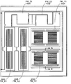
- FIG. 1C illustrates an accelerometer with six proof masses 200 a , 200 b , 300 a , 300 b , 400 a and 400 b in accordance with the present invention.
- proof masses 200 a and 200 b are for the X-axis accelerometer
- proof masses 300 a and 300 b are for the Y-axis accelerometer
- proof masses 400 a and 400 b are for the Z-axis accelerometer.
- FIGS. 2A and 2B illustrate one structure 250 for an X-axis accelerometer and one structure 350 for a Y-axis accelerometer, respectively, in accordance with the present invention.
- the structures 250 and 350 can be utilized interchangeably to enable the best use of the available area.
- Each of the x-axis accelerometer and y-axis accelerometer would utilize one or more of these structures to measure acceleration in two directions.
- Each of the accelerometers 250 and 350 comprise a proof mass 200 and 300 , flexural springs 202 and 302 and dampers 204 and 304 .
- the mechanical parts are fabricated for example, by using deep reactive ion etching (DRIE) of a low resistivity single crystal silicon wafer.
- the proof mass 200 and 300 is attached to an anchor 206 and 306 through the flexural springs 202 and 302 as shown in FIGS. 2A and 2B .
- the anchors 206 and 306 are attached to an upper cover (not shown) for example by diffusion bonding and are attached to the CMOS die (not shown), for example, by eutectic bonding.
- An oxide layer electrically insulates the anchor 206 and 306 and therefore the proof mass 200 and 300 from the cover but eutectic bond between the anchor and the CMOS electronics enables the electrical connections to the proof mass 200 and 300 .
- the proof masses 200 and 300 can be also connected to the substrate electrically through a soft spring.
- the main difference between the structure 250 and the structure 350 is that structure 250 uses a two folded flexural springs 209 whereas structure 350 uses four folded flexural springs 302 . By increasing the number of folds one can reduce the length of the springs while keeping the spring constant the same. This allows combining sensors with different aspect ratios on the substrate for efficient use of the surface area.
- the motion of the proof mass 200 and 300 is sensed by parallel plate electrodes 208 a , 208 b and 308 a , 308 b that are placed perpendicular to the motion of the proof mass 200 and 300 .
- the electrodes 208 a , 208 b and 308 a , 308 b are held fixed by means of diffusion and eutectic bond.
- Each pair of electrodes 208 a , 208 b and 308 a , 308 b is used to enable differential capacitance sensing.
- the capacitance sensing can be implemented utilizing a bridge configuration. This feature will be described in detail later in this specification.
- the dampers 204 and 304 allow for the proper operation of the accelerometers in a low pressure vacuum environment which is required for the rate sensor operation.
- FIG. 2C shows bumps along the dampers to increase the damping effect. The bumps along the dampers reduce the gap in between without pushing the limits of the DRIE process.
- the over range limiters (stoppers) 210 and 310 are provided in the sense direction since in this direction the springs have the lowest spring constants.
- the over range limit in the other directions can be either provided by other sets of stoppers or by making the spring constants very high.
- a single anchor 206 and 306 point connects the structures to the substrate. Therefore, the effect of relative stress between the package and the substrate is minimized on the performance of the accelerometer.
- self test electrodes 212 and 312 are also incorporated into the accelerometers as shown in FIGS. 2A and 2B .
- FIGS. 3A and 3B illustrate a top view and a side view, respectively of a Z axis accelerometer 450 in accordance with the present invention.
- the figure illustrates usage of two proof masses per axis, but only one structure can also be used for acceleration detection in Z-direction.
- Both structures of the accelerometer are depicted in the figures unlike FIGS. 2A and 2B where only one of the structures for the accelerometers is depicted per axis.
- the two structures are packed such that to make the best use of available chip area.
- a lever arm for each structure 410 a and 410 b pivoted at the center is attached to three proof mass systems 401 a , 403 a , 405 a and 401 b , 403 b and 405 b .
- the total weight on the each side of the lever arm 410 a and 410 b is different. When there is acceleration in the Z direction this results in a bending of the lever arm around the pivot point.
- the electrodes 408 a and 408 b placed under the outer most proof mass systems 401 a , 405 a , 401 b and 405 b on the CMOS reference substrate 409 enable differential measurement.
- the center proof mass 403 a and 403 b adds more weight to one side of the lever arm.
- a thin film under proof masses 403 a and 403 b reducing the gap between the CMOS die and the proof mass.
- the placement and the shape of the proof masses are chosen such that the two accelerometers can be fit in a very small area as shown FIG. 3A .
- the spring constant of the Z-axis accelerometer is also low in Y-axis direction. This makes it sensitive to the Y-axis acceleration. If there is no process variation along the thickness direction or if the side walls are perfectly 90 degrees this does not cause any cross-axis sensitivity since the capacitance will not change with translational motion provided that the electrodes on the CMOS are smaller than the proof masses.
- FIG. 4 illustrates a circuit 500 which is electrode driven for sensing a change in capacitance in an accelerometer in accordance with the present invention.
- an AC voltage 502 is applied to the sense electrodes 804 a and 504 b and the output voltage is detected off the proof masses 508 a and 508 b utilizing an operational amplifier 506 .
- the output voltage is zero. Acceleration of the proof masses 508 a and 508 b gives rise to an AC voltage at the operational amplifier output which can be demodulated later.
- FIG. 5 illustrates a circuit 600 which is proof mass driven for sensing a change in capacitance in an accelerometer in accordance with the present invention.
- the advantage of the circuit of FIG. 5 is that the AC drive does not cause any motion on the proof masses 508 a ′ and 508 b ′.
- the detection is determined by the amount of parasitic capacitances 604 a and 604 b .
- the operational amplifier 506 ′ is connected to the nodes where the parasitic capacitances 604 a and 604 b are lower.
- FIG. 6 shows a combined X (or Y) axis and Z axis accelerometer.
- X or Y
- Z axis accelerometer For example, one can easily combine Y axis and Z axis by just adding electrodes 652 to the sides of the structure for the z-axis accelerometer. Since these structures are built using bulk micromachining the thickness is high allowing relatively high capacitance in the thickness direction.
- the accelerometer shown in FIG. 6 can be also be used in X direction by just rotating it.
- FIG. 7 shows another accelerometer 750 where all axes are combined. This allows very efficient use of chip area.
- the accelerometer shown in FIG. 7 combines all the proof masses.
- X-axis and y-axis acceleration sense electrodes 701 and 703 are similar to the structures shown in FIGS. 2A and 2B .
- the center proof mass moves out of plane while bending the edge proof masses around the pivot points 702 and 704 . This allows differential capacitance detection for the z-axis measurement.
Abstract
Description
Claims (22)
Priority Applications (6)
| Application Number | Priority Date | Filing Date | Title |
|---|---|---|---|
| US11/766,776 US8047075B2 (en) | 2007-06-21 | 2007-06-21 | Vertically integrated 3-axis MEMS accelerometer with electronics |
| US12/398,156 US20090262074A1 (en) | 2007-01-05 | 2009-03-04 | Controlling and accessing content using motion processing on mobile devices |
| US12/485,823 US8462109B2 (en) | 2007-01-05 | 2009-06-16 | Controlling and accessing content using motion processing on mobile devices |
| US12/782,608 US7907838B2 (en) | 2007-01-05 | 2010-05-18 | Motion sensing and processing on mobile devices |
| US13/046,623 US8351773B2 (en) | 2007-01-05 | 2011-03-11 | Motion sensing and processing on mobile devices |
| US13/910,485 US9292102B2 (en) | 2007-01-05 | 2013-06-05 | Controlling and accessing content using motion processing on mobile devices |
Applications Claiming Priority (1)
| Application Number | Priority Date | Filing Date | Title |
|---|---|---|---|
| US11/766,776 US8047075B2 (en) | 2007-06-21 | 2007-06-21 | Vertically integrated 3-axis MEMS accelerometer with electronics |
Related Parent Applications (2)
| Application Number | Title | Priority Date | Filing Date |
|---|---|---|---|
| US11/649,936 Continuation-In-Part US7796872B2 (en) | 2007-01-05 | 2007-01-05 | Method and apparatus for producing a sharp image from a handheld device containing a gyroscope |
| US11/774,488 Continuation-In-Part US8250921B2 (en) | 2007-01-05 | 2007-07-06 | Integrated motion processing unit (MPU) with MEMS inertial sensing and embedded digital electronics |
Related Child Applications (2)
| Application Number | Title | Priority Date | Filing Date |
|---|---|---|---|
| US11/649,936 Continuation-In-Part US7796872B2 (en) | 2007-01-05 | 2007-01-05 | Method and apparatus for producing a sharp image from a handheld device containing a gyroscope |
| US11/774,488 Continuation-In-Part US8250921B2 (en) | 2007-01-05 | 2007-07-06 | Integrated motion processing unit (MPU) with MEMS inertial sensing and embedded digital electronics |
Publications (2)
| Publication Number | Publication Date |
|---|---|
| US20080314147A1 US20080314147A1 (en) | 2008-12-25 |
| US8047075B2 true US8047075B2 (en) | 2011-11-01 |
Family
ID=40135111
Family Applications (1)
| Application Number | Title | Priority Date | Filing Date |
|---|---|---|---|
| US11/766,776 Active 2028-04-30 US8047075B2 (en) | 2007-01-05 | 2007-06-21 | Vertically integrated 3-axis MEMS accelerometer with electronics |
Country Status (1)
| Country | Link |
|---|---|
| US (1) | US8047075B2 (en) |
Cited By (41)
| Publication number | Priority date | Publication date | Assignee | Title |
|---|---|---|---|---|
| US20100024554A1 (en) * | 2008-07-30 | 2010-02-04 | Johannes Classen | Triaxial acceleration sensor |
| US20100083756A1 (en) * | 2007-04-05 | 2010-04-08 | Fraunhofer-Gesellschaft zur Foeerderung der angewa | Micromechanical Inertial Sensor for Measuring Rotation Rates |
| US20100122579A1 (en) * | 2008-11-18 | 2010-05-20 | Industrial Technology Research Institute | Multi-axis capacitive accelerometer |
| US20100206075A1 (en) * | 2009-02-17 | 2010-08-19 | Seiko Epson Corporation | Composite sensor and electronic device |
| US20100257933A1 (en) * | 2007-07-24 | 2010-10-14 | Nxp B.V. | Multi-axial linear and rotational displacement sensor |
| US20110011182A1 (en) * | 2009-07-16 | 2011-01-20 | Mitsubishi Electric Corporation | Capacitive acceleration sensor |
| US20110056295A1 (en) * | 2009-09-04 | 2011-03-10 | Johannes Classen | Micromechanical system |
| US20120017681A1 (en) * | 2009-02-04 | 2012-01-26 | Jochen Reinmuth | Acceleration sensor method for operating an acceleration sensor |
| US20120055249A1 (en) * | 2009-06-03 | 2012-03-08 | Alps Electric Co., Ltd. | Physical quantity sensor |
| US20120126348A1 (en) * | 2010-11-23 | 2012-05-24 | Honeywell International Inc. | Systems and methods for a four-layer chip-scale mems device |
| US20140090471A1 (en) * | 2011-12-13 | 2014-04-03 | Ying Wen Hsu | Three-Axis Nano-Resonator Accelerometer Device and Method |
| US8952832B2 (en) | 2008-01-18 | 2015-02-10 | Invensense, Inc. | Interfacing application programs and motion sensors of a device |
| US8960002B2 (en) | 2007-12-10 | 2015-02-24 | Invensense, Inc. | Vertically integrated 3-axis MEMS angular accelerometer with integrated electronics |
| US20150068308A1 (en) * | 2013-09-11 | 2015-03-12 | Murata Manufacturing Co., Ltd. | Gyroscope structure and gyroscope |
| US20150082885A1 (en) * | 2013-09-11 | 2015-03-26 | Murata Manufacturing Co., Ltd. | Gyroscope structure and gyroscope with improved quadrature compensation |
| US8997564B2 (en) | 2007-07-06 | 2015-04-07 | Invensense, Inc. | Integrated motion processing unit (MPU) with MEMS inertial sensing and embedded digital electronics |
| US9008757B2 (en) | 2012-09-26 | 2015-04-14 | Stryker Corporation | Navigation system including optical and non-optical sensors |
| US20150143904A1 (en) * | 2013-11-25 | 2015-05-28 | Seiko Epson Corporation | Functional element, electronic device, and moving object |
| US9171964B2 (en) | 2010-11-23 | 2015-10-27 | Honeywell International Inc. | Systems and methods for a three-layer chip-scale MEMS device |
| CN105004883A (en) * | 2014-04-18 | 2015-10-28 | 精工爱普生株式会社 | Electronic device, electronic apparatus, and moving object |
| US9292102B2 (en) | 2007-01-05 | 2016-03-22 | Invensense, Inc. | Controlling and accessing content using motion processing on mobile devices |
| CN105445496A (en) * | 2014-09-18 | 2016-03-30 | 硕英股份有限公司 | Three-axis accelerometer |
| US9309106B2 (en) | 2013-07-08 | 2016-04-12 | Motion Engine Inc. | 3D MEMS device and method of manufacturing |
| CN106370889A (en) * | 2015-07-21 | 2017-02-01 | 飞思卡尔半导体公司 | Multi-axis inertial sensor with dual mass and integrated damping structure |
| US9830043B2 (en) | 2012-08-21 | 2017-11-28 | Beijing Lenovo Software Ltd. | Processing method and processing device for displaying icon and electronic device |
| US9834432B2 (en) | 2013-04-25 | 2017-12-05 | Commissariat à l'énergie atomique et aux énergies alternatives | Microelectromechanical and/or nanoelectromechanical structure with a variable quality factor |
| CN107576322A (en) * | 2012-02-01 | 2018-01-12 | 快捷半导体公司 | Microelectromechanical systems with separated z-axis part(MEMS)Mass |
| US10214414B2 (en) | 2014-01-09 | 2019-02-26 | Motion Engine, Inc. | Integrated MEMS system |
| US10231337B2 (en) | 2014-12-16 | 2019-03-12 | Inertial Sense, Inc. | Folded printed circuit assemblies and related methods |
| US10273147B2 (en) | 2013-07-08 | 2019-04-30 | Motion Engine Inc. | MEMS components and method of wafer-level manufacturing thereof |
| US10407299B2 (en) | 2015-01-15 | 2019-09-10 | Motion Engine Inc. | 3D MEMS device with hermetic cavity |
| US10429407B2 (en) | 2017-03-27 | 2019-10-01 | Nxp Usa, Inc. | Three-axis inertial sensor for detecting linear acceleration forces |
| US10591318B2 (en) | 2017-08-31 | 2020-03-17 | Invensense, Inc. | Half-bridge circuit for a sensor |
| US10768065B2 (en) | 2014-04-10 | 2020-09-08 | Mei Micro, Inc. | MEMS pressure sensor |
| US10809277B2 (en) | 2017-12-18 | 2020-10-20 | Nxp Usa, Inc. | Single axis inertial sensor with suppressed parasitic modes |
| US11009350B2 (en) | 2018-01-11 | 2021-05-18 | Invensense, Inc. | Proof mass offset compensation |
| US11287486B2 (en) | 2014-12-09 | 2022-03-29 | Motion Engine, Inc. | 3D MEMS magnetometer and associated methods |
| US11674803B2 (en) | 2014-06-02 | 2023-06-13 | Motion Engine, Inc. | Multi-mass MEMS motion sensor |
| US11852481B2 (en) | 2013-08-02 | 2023-12-26 | Motion Engine Inc. | MEMS motion sensor and method of manufacturing |
| US11860048B2 (en) | 2017-07-10 | 2024-01-02 | The Board Of Trustees Of The Leland Stanford Junior University | Capacitive and tactile sensors and related sensing methods |
| US11892467B2 (en) | 2020-12-18 | 2024-02-06 | Analog Devices, Inc. | Accelerometer with translational motion of masses |
Families Citing this family (58)
| Publication number | Priority date | Publication date | Assignee | Title |
|---|---|---|---|---|
| US20100071467A1 (en) * | 2008-09-24 | 2010-03-25 | Invensense | Integrated multiaxis motion sensor |
| US7796872B2 (en) * | 2007-01-05 | 2010-09-14 | Invensense, Inc. | Method and apparatus for producing a sharp image from a handheld device containing a gyroscope |
| US8141424B2 (en) | 2008-09-12 | 2012-03-27 | Invensense, Inc. | Low inertia frame for detecting coriolis acceleration |
| US8047075B2 (en) | 2007-06-21 | 2011-11-01 | Invensense, Inc. | Vertically integrated 3-axis MEMS accelerometer with electronics |
| US20090265671A1 (en) * | 2008-04-21 | 2009-10-22 | Invensense | Mobile devices with motion gesture recognition |
| US8020441B2 (en) | 2008-02-05 | 2011-09-20 | Invensense, Inc. | Dual mode sensing for vibratory gyroscope |
| US8508039B1 (en) | 2008-05-08 | 2013-08-13 | Invensense, Inc. | Wafer scale chip scale packaging of vertically integrated MEMS sensors with electronics |
| US8956904B2 (en) | 2008-09-10 | 2015-02-17 | Analog Devices, Inc. | Apparatus and method of wafer bonding using compatible alloy |
| US7981765B2 (en) | 2008-09-10 | 2011-07-19 | Analog Devices, Inc. | Substrate bonding with bonding material having rare earth metal |
| DE102009001847B4 (en) | 2009-03-25 | 2022-07-28 | Robert Bosch Gmbh | Micromechanical component, sensor device with a micromechanical component and method for operating a micromechanical component |
| JP2012528335A (en) * | 2009-05-27 | 2012-11-12 | キング アブドゥーラ ユニバーシティ オブ サイエンス アンド テクノロジー | MEMS mass-spring-damper system using out-of-plane suspension system |
| US8427508B2 (en) * | 2009-06-25 | 2013-04-23 | Nokia Corporation | Method and apparatus for an augmented reality user interface |
| US8739626B2 (en) | 2009-08-04 | 2014-06-03 | Fairchild Semiconductor Corporation | Micromachined inertial sensor devices |
| DE102009045645B4 (en) | 2009-10-13 | 2023-01-19 | Robert Bosch Gmbh | Sensor device and manufacturing method for a sensor device |
| US8543917B2 (en) | 2009-12-11 | 2013-09-24 | Nokia Corporation | Method and apparatus for presenting a first-person world view of content |
| US8966400B2 (en) | 2010-06-07 | 2015-02-24 | Empire Technology Development Llc | User movement interpretation in computer generated reality |
| EP2616771B8 (en) | 2010-09-18 | 2018-12-19 | Fairchild Semiconductor Corporation | Micromachined monolithic 6-axis inertial sensor |
| KR20130057485A (en) | 2010-09-18 | 2013-05-31 | 페어차일드 세미컨덕터 코포레이션 | Packaging to reduce stress on microelectromechanical systems |
| KR101871865B1 (en) | 2010-09-18 | 2018-08-02 | 페어차일드 세미컨덕터 코포레이션 | Multi-die mems package |
| US9278845B2 (en) | 2010-09-18 | 2016-03-08 | Fairchild Semiconductor Corporation | MEMS multi-axis gyroscope Z-axis electrode structure |
| WO2012037501A2 (en) | 2010-09-18 | 2012-03-22 | Cenk Acar | Flexure bearing to reduce quadrature for resonating micromachined devices |
| CN103221778B (en) * | 2010-09-18 | 2016-03-30 | 快捷半导体公司 | There is single micromechanics one chip three-axis gyroscope driven |
| KR101311966B1 (en) | 2010-09-20 | 2013-10-14 | 페어차일드 세미컨덕터 코포레이션 | Through silicon via with reduced shunt capacitance |
| US10065851B2 (en) | 2010-09-20 | 2018-09-04 | Fairchild Semiconductor Corporation | Microelectromechanical pressure sensor including reference capacitor |
| KR20130132900A (en) * | 2010-12-07 | 2013-12-05 | 조지아 테크 리서치 코포레이션 | Mode-matched single proof-mass dual-axis gyroscope and method of fabrication |
| US9395410B2 (en) * | 2011-06-06 | 2016-07-19 | Iii Holdings 1, Llc | Integrated circuit with sensing unit and method for using the same |
| US9062972B2 (en) | 2012-01-31 | 2015-06-23 | Fairchild Semiconductor Corporation | MEMS multi-axis accelerometer electrode structure |
| US8754694B2 (en) | 2012-04-03 | 2014-06-17 | Fairchild Semiconductor Corporation | Accurate ninety-degree phase shifter |
| US8742964B2 (en) | 2012-04-04 | 2014-06-03 | Fairchild Semiconductor Corporation | Noise reduction method with chopping for a merged MEMS accelerometer sensor |
| US9488693B2 (en) | 2012-04-04 | 2016-11-08 | Fairchild Semiconductor Corporation | Self test of MEMS accelerometer with ASICS integrated capacitors |
| EP2647955B8 (en) | 2012-04-05 | 2018-12-19 | Fairchild Semiconductor Corporation | MEMS device quadrature phase shift cancellation |
| EP2647952B1 (en) | 2012-04-05 | 2017-11-15 | Fairchild Semiconductor Corporation | Mems device automatic-gain control loop for mechanical amplitude drive |
| US9069006B2 (en) | 2012-04-05 | 2015-06-30 | Fairchild Semiconductor Corporation | Self test of MEMS gyroscope with ASICs integrated capacitors |
| KR102058489B1 (en) | 2012-04-05 | 2019-12-23 | 페어차일드 세미컨덕터 코포레이션 | Mems device front-end charge amplifier |
| US9094027B2 (en) | 2012-04-12 | 2015-07-28 | Fairchild Semiconductor Corporation | Micro-electro-mechanical-system (MEMS) driver |
| US9625272B2 (en) | 2012-04-12 | 2017-04-18 | Fairchild Semiconductor Corporation | MEMS quadrature cancellation and signal demodulation |
| DE102013014881B4 (en) | 2012-09-12 | 2023-05-04 | Fairchild Semiconductor Corporation | Enhanced silicon via with multi-material fill |
| JP6070111B2 (en) * | 2012-11-27 | 2017-02-01 | 株式会社村田製作所 | Acceleration sensor |
| US9316666B2 (en) * | 2012-11-27 | 2016-04-19 | Murata Manufacturing Co., Ltd. | Acceleration sensor having a capacitor array located in the center of an inertial mass |
| US10036635B2 (en) | 2013-01-25 | 2018-07-31 | MCube Inc. | Multi-axis MEMS rate sensor device |
| US10132630B2 (en) * | 2013-01-25 | 2018-11-20 | MCube Inc. | Multi-axis integrated MEMS inertial sensing device on single packaged chip |
| US10913653B2 (en) * | 2013-03-07 | 2021-02-09 | MCube Inc. | Method of fabricating MEMS devices using plasma etching and device therefor |
| JP2015045600A (en) * | 2013-08-29 | 2015-03-12 | セイコーエプソン株式会社 | Functional element, electronic device, and movable body |
| JP6020392B2 (en) | 2013-09-03 | 2016-11-02 | 株式会社デンソー | Acceleration sensor |
| CN104698222B (en) * | 2015-02-15 | 2017-06-16 | 东南大学 | Three axle single-chip integration resonant capacitance formula silicon micro accerometers and its processing method |
| US10012671B2 (en) * | 2015-11-03 | 2018-07-03 | Richtek Technology Corporation | Micro-electro-mechanical system device |
| US10393770B2 (en) * | 2016-04-28 | 2019-08-27 | Semiconductor Components Industries, Llc | Multi-axis accelerometer with reduced stress sensitivity |
| KR101915954B1 (en) * | 2016-06-29 | 2018-11-08 | 주식회사 신성씨앤티 | MEMS based 3-axis accelerometer |
| US10697994B2 (en) | 2017-02-22 | 2020-06-30 | Semiconductor Components Industries, Llc | Accelerometer techniques to compensate package stress |
| US10759656B2 (en) * | 2017-09-29 | 2020-09-01 | Apple Inc. | MEMS sensor with dual pendulous proof masses |
| US10816568B2 (en) * | 2017-12-26 | 2020-10-27 | Physical Logic Ltd. | Closed loop accelerometer |
| EP3598146B1 (en) | 2018-07-16 | 2022-05-11 | Murata Manufacturing Co., Ltd. | Microelectromechanical device for out-of-plane motion detection |
| CN112748258A (en) * | 2019-10-31 | 2021-05-04 | 美新半导体(无锡)有限公司 | Triaxial accelerometer based on single mass block |
| GB2595294A (en) * | 2020-05-21 | 2021-11-24 | Cambridge Entpr Ltd | Single axis resonant accelerometer |
| DE102020211928A1 (en) | 2020-09-23 | 2022-05-19 | Robert Bosch Gesellschaft mit beschränkter Haftung | Damping device for micromechanical component |
| CN112858723B (en) * | 2021-01-14 | 2023-06-09 | 南京理工大学 | Interference mode suppression device and method for silicon micro-resonant accelerometer |
| JP2023066598A (en) * | 2021-10-29 | 2023-05-16 | セイコーエプソン株式会社 | Physical quantity sensor and inertial measurement device |
| DE102022200338A1 (en) | 2022-01-13 | 2023-07-13 | Robert Bosch Gesellschaft mit beschränkter Haftung | Micromechanical sensor device |
Citations (178)
| Publication number | Priority date | Publication date | Assignee | Title |
|---|---|---|---|---|
| US4510802A (en) | 1983-09-02 | 1985-04-16 | Sundstrand Data Control, Inc. | Angular rate sensor utilizing two vibrating accelerometers secured to a parallelogram linkage |
| US4601206A (en) | 1983-09-16 | 1986-07-22 | Ferranti Plc | Accelerometer system |
| US4736629A (en) | 1985-12-20 | 1988-04-12 | Silicon Designs, Inc. | Micro-miniature accelerometer |
| US4783742A (en) | 1986-12-31 | 1988-11-08 | Sundstrand Data Control, Inc. | Apparatus and method for gravity correction in borehole survey systems |
| US4841773A (en) | 1987-05-01 | 1989-06-27 | Litton Systems, Inc. | Miniature inertial measurement unit |
| US5251484A (en) | 1992-04-03 | 1993-10-12 | Hewlett-Packard Company | Rotational accelerometer |
| US5349858A (en) | 1991-01-29 | 1994-09-27 | Canon Kabushiki Kaisha | Angular acceleration sensor |
| US5359893A (en) | 1991-12-19 | 1994-11-01 | Motorola, Inc. | Multi-axes gyroscope |
| US5367631A (en) | 1992-04-14 | 1994-11-22 | Apple Computer, Inc. | Cursor control device with programmable preset cursor positions |
| US5415040A (en) | 1993-03-03 | 1995-05-16 | Zexel Corporation | Acceleration sensor |
| US5433110A (en) | 1992-10-29 | 1995-07-18 | Sextant Avionique | Detector having selectable multiple axes of sensitivity |
| US5440326A (en) | 1990-03-21 | 1995-08-08 | Gyration, Inc. | Gyroscopic pointer |
| US5444639A (en) | 1993-09-07 | 1995-08-22 | Rockwell International Corporation | Angular rate sensing system and method, with digital synthesizer and variable-frequency oscillator |
| EP0429391B1 (en) | 1989-11-06 | 1995-08-23 | International Business Machines Corporation | Three-dimensional computer input device |
| US5511419A (en) | 1991-12-19 | 1996-04-30 | Motorola | Rotational vibration gyroscope |
| US5541860A (en) | 1988-06-22 | 1996-07-30 | Fujitsu Limited | Small size apparatus for measuring and recording acceleration |
| US5574221A (en) | 1993-10-29 | 1996-11-12 | Samsung Electro-Mechanics Co., Ltd. | Angular acceleration sensor |
| US5629988A (en) | 1993-06-04 | 1997-05-13 | David Sarnoff Research Center, Inc. | System and method for electronic image stabilization |
| US5635638A (en) | 1995-06-06 | 1997-06-03 | Analog Devices, Inc. | Coupling for multiple masses in a micromachined device |
| US5698784A (en) | 1996-01-24 | 1997-12-16 | Gyration, Inc. | Vibratory rate gyroscope and methods of assembly and operation |
| US5703293A (en) | 1995-05-27 | 1997-12-30 | Robert Bosch Gmbh | Rotational rate sensor with two acceleration sensors |
| US5703623A (en) | 1996-01-24 | 1997-12-30 | Hall; Malcolm G. | Smart orientation sensing circuit for remote control |
| US5734373A (en) | 1993-07-16 | 1998-03-31 | Immersion Human Interface Corporation | Method and apparatus for controlling force feedback interface systems utilizing a host computer |
| US5780740A (en) | 1995-10-27 | 1998-07-14 | Samsung Electronics Co., Ltd. | Vibratory structure, method for controlling natural frequency thereof, and actuator, sensor, accelerator, gyroscope and gyroscope natural frequency controlling method using vibratory structure |
| US5825350A (en) | 1996-03-13 | 1998-10-20 | Gyration, Inc. | Electronic pointing apparatus and method |
| US5895850A (en) | 1994-04-23 | 1999-04-20 | Robert Bosch Gmbh | Micromechanical resonator of a vibration gyrometer |
| US5955668A (en) | 1997-01-28 | 1999-09-21 | Irvine Sensors Corporation | Multi-element micro gyro |
| US5992233A (en) | 1996-05-31 | 1999-11-30 | The Regents Of The University Of California | Micromachined Z-axis vibratory rate gyroscope |
| US5996409A (en) | 1997-05-10 | 1999-12-07 | Robert Bosch Gmbh | Acceleration sensing device |
| US6122961A (en) | 1997-09-02 | 2000-09-26 | Analog Devices, Inc. | Micromachined gyros |
| US6134961A (en) | 1998-06-24 | 2000-10-24 | Aisin Seiki Kabushiki Kaisha | Angular velocity sensor |
| US6158280A (en) | 1997-12-22 | 2000-12-12 | Kabushiki Kaisha Toyota Chuo Kenkyusho | Detector for detecting angular velocities about perpendicular axes |
| US6168965B1 (en) | 1999-08-12 | 2001-01-02 | Tower Semiconductor Ltd. | Method for making backside illuminated image sensor |
| US6189381B1 (en) | 1999-04-26 | 2001-02-20 | Sitek, Inc. | Angular rate sensor made from a structural wafer of single crystal silicon |
| US6230564B1 (en) * | 1998-02-19 | 2001-05-15 | Akebono Brake Industry Co., Ltd. | Semiconductor acceleration sensor and its self-diagnosing method |
| US6250156B1 (en) | 1996-05-31 | 2001-06-26 | The Regents Of The University Of California | Dual-mass micromachined vibratory rate gyroscope |
| US6250157B1 (en) | 1998-06-22 | 2001-06-26 | Aisin Seiki Kabushiki Kaisha | Angular rate sensor |
| US6269254B1 (en) | 1998-09-28 | 2001-07-31 | Motorola, Inc. | Radio communications device and method with API between user application program and telephony program and method |
| US6279043B1 (en) | 1998-05-01 | 2001-08-21 | Apple Computer, Inc. | Method and system for script access to API functionality |
| US6292170B1 (en) | 1997-04-25 | 2001-09-18 | Immersion Corporation | Designing compound force sensations for computer applications |
| US6343349B1 (en) | 1997-11-14 | 2002-01-29 | Immersion Corporation | Memory caching for force feedback effects |
| US20020027296A1 (en) | 1999-12-10 | 2002-03-07 | Badehi Avner Pierre | Methods for producing packaged integrated circuit devices & packaged integrated circuit devices produced thereby |
| US6370937B2 (en) | 2000-03-17 | 2002-04-16 | Microsensors, Inc. | Method of canceling quadrature error in an angular rate sensor |
| US6374255B1 (en) | 1996-05-21 | 2002-04-16 | Immersion Corporation | Haptic authoring |
| US6386033B1 (en) | 1998-07-10 | 2002-05-14 | Murata Manufacturing Co., | Angular velocity sensor |
| US6391673B1 (en) | 1999-11-04 | 2002-05-21 | Samsung Electronics Co., Ltd. | Method of fabricating micro electro mechanical system structure which can be vacuum-packed at wafer level |
| US6393914B1 (en) | 2001-02-13 | 2002-05-28 | Delphi Technologies, Inc. | Angular accelerometer |
| US6424356B2 (en) | 1999-05-05 | 2002-07-23 | Immersion Corporation | Command of force sensations in a forceback system using force effect suites |
| US6429895B1 (en) | 1996-12-27 | 2002-08-06 | Canon Kabushiki Kaisha | Image sensing apparatus and method capable of merging function for obtaining high-precision image by synthesizing images and image stabilization function |
| US6430998B2 (en) | 1999-12-03 | 2002-08-13 | Murata Manufacturing Co., Ltd. | Resonant element |
| US6480320B2 (en) | 2001-02-07 | 2002-11-12 | Transparent Optical, Inc. | Microelectromechanical mirror and mirror array |
| US6481283B1 (en) | 1999-04-05 | 2002-11-19 | Milli Sensor Systems & Actuators, Inc. | Coriolis oscillating gyroscopic instrument |
| US6481285B1 (en) | 1999-04-21 | 2002-11-19 | Andrei M. Shkel | Micro-machined angle-measuring gyroscope |
| US6487369B1 (en) | 1999-04-26 | 2002-11-26 | Olympus Optical Co., Ltd. | Camera with blur reducing function |
| US6494096B2 (en) * | 2000-03-16 | 2002-12-17 | Denso Corporation | Semiconductor physical quantity sensor |
| US20020189351A1 (en) | 2001-06-14 | 2002-12-19 | Reeds John W. | Angular rate sensor having a sense element constrained to motion about a single axis and flexibly attached to a rotary drive mass |
| US6508125B2 (en) * | 2000-09-07 | 2003-01-21 | Mitsubishi Denki Kabushiki Kaisha | Electrostatic capacitance type acceleration sensor, electrostatic capacitance type angular acceleration sensor and electrostatic actuator |
| US6508122B1 (en) | 1999-09-16 | 2003-01-21 | American Gnc Corporation | Microelectromechanical system for measuring angular rate |
| US6513380B2 (en) | 2001-06-19 | 2003-02-04 | Microsensors, Inc. | MEMS sensor with single central anchor and motion-limiting connection geometry |
| US6520017B1 (en) | 1999-08-12 | 2003-02-18 | Robert Bosch Gmbh | Micromechanical spin angular acceleration sensor |
| US6573883B1 (en) | 1998-06-24 | 2003-06-03 | Hewlett Packard Development Company, L.P. | Method and apparatus for controlling a computing device with gestures |
| US20030159511A1 (en) | 2002-02-28 | 2003-08-28 | Zarabadi Seyed R. | Angular accelerometer having balanced inertia mass |
| US6636521B1 (en) | 1998-12-18 | 2003-10-21 | Lucent Technologies Inc. | Flexible runtime configurable application program interface (API) that is command independent and reusable |
| US6646289B1 (en) | 1998-02-06 | 2003-11-11 | Shellcase Ltd. | Integrated circuit device |
| US6668614B2 (en) * | 2001-10-16 | 2003-12-30 | Denso Corporation | Capacitive type physical quantity detecting sensor for detecting physical quantity along plural axes |
| US20040016995A1 (en) | 2002-07-25 | 2004-01-29 | Kuo Shun Meen | MEMS control chip integration |
| US20040066981A1 (en) | 2001-04-09 | 2004-04-08 | Mingjing Li | Hierarchical scheme for blur detection in digital image using wavelet transform |
| US6720994B1 (en) | 1999-10-28 | 2004-04-13 | Raytheon Company | System and method for electronic stabilization for second generation forward looking infrared systems |
| US6725719B2 (en) | 2002-04-17 | 2004-04-27 | Milli Sensor Systems And Actuators, Inc. | MEMS-integrated inertial measurement units on a common substrate |
| US6758093B2 (en) | 1999-07-08 | 2004-07-06 | California Institute Of Technology | Microgyroscope with integrated vibratory element |
| US20040160525A1 (en) | 2003-02-14 | 2004-08-19 | Minolta Co., Ltd. | Image processing apparatus and method |
| US20040179108A1 (en) | 2003-03-11 | 2004-09-16 | Sightic Vista Ltd. | Adaptive low-light image processing |
| US6794272B2 (en) | 2001-10-26 | 2004-09-21 | Ifire Technologies, Inc. | Wafer thinning using magnetic mirror plasma |
| US6796178B2 (en) | 2002-02-08 | 2004-09-28 | Samsung Electronics Co., Ltd. | Rotation-type decoupled MEMS gyroscope |
| US6823733B2 (en) | 2002-11-04 | 2004-11-30 | Matsushita Electric Industrial Co., Ltd. | Z-axis vibration gyroscope |
| US6834249B2 (en) | 2001-03-29 | 2004-12-21 | Arraycomm, Inc. | Method and apparatus for controlling a computing system |
| US6845669B2 (en) | 2001-05-02 | 2005-01-25 | The Regents Of The University Of California | Non-resonant four degrees-of-freedom micromachined gyroscope |
| US6848304B2 (en) | 2003-04-28 | 2005-02-01 | Analog Devices, Inc. | Six degree-of-freedom micro-machined multi-sensor |
| US6859751B2 (en) | 2001-12-17 | 2005-02-22 | Milli Sensor Systems & Actuators, Inc. | Planar inertial measurement units based on gyros and accelerometers with a common structure |
| US6860150B2 (en) | 2002-10-12 | 2005-03-01 | Samsung Electro-Mechanics Co., Ltd. | Microgyroscope tunable for translational acceleration |
| US20050066728A1 (en) | 2003-09-25 | 2005-03-31 | Kionix, Inc. | Z-axis angular rate micro electro-mechanical systems (MEMS) sensor |
| US6892575B2 (en) | 2003-10-20 | 2005-05-17 | Invensense Inc. | X-Y axis dual-mass tuning fork gyroscope with vertically integrated electronics and wafer-scale hermetic packaging |
| US20050110778A1 (en) | 2000-12-06 | 2005-05-26 | Mourad Ben Ayed | Wireless handwriting input device using grafitis and bluetooth |
| US6915693B2 (en) | 2001-12-14 | 2005-07-12 | Samsung Electronics Co., Ltd. | MEMS gyroscope having mass vibrating vertically on substrate |
| US6918297B2 (en) | 2003-02-28 | 2005-07-19 | Honeywell International, Inc. | Miniature 3-dimensional package for MEMS sensors |
| US6918298B2 (en) | 2002-12-24 | 2005-07-19 | Samsung Electro-Mechanics Co., Ltd. | Horizontal and tuning fork vibratory microgyroscope |
| US20050170656A1 (en) | 2003-10-20 | 2005-08-04 | Nasiri Steven S. | Vertical integration of a MEMS structure with electronics in a hermetically sealed cavity |
| US6938484B2 (en) * | 2003-01-16 | 2005-09-06 | The Regents Of The University Of Michigan | Micromachined capacitive lateral accelerometer device and monolithic, three-axis accelerometer having same |
| US6939473B2 (en) | 2003-10-20 | 2005-09-06 | Invensense Inc. | Method of making an X-Y axis dual-mass tuning fork gyroscope with vertically integrated electronics and wafer-scale hermetic packaging |
| US20050212751A1 (en) | 2004-03-23 | 2005-09-29 | Marvit David L | Customizable gesture mappings for motion controlled handheld devices |
| US6955086B2 (en) * | 2001-11-19 | 2005-10-18 | Mitsubishi Denki Kabushiki Kaisha | Acceleration sensor |
| US6963345B2 (en) | 2000-03-07 | 2005-11-08 | Microsoft Corporation | API communications for vertex and pixel shaders |
| US6972480B2 (en) | 2003-06-16 | 2005-12-06 | Shellcase Ltd. | Methods and apparatus for packaging integrated circuit devices |
| US6981416B2 (en) * | 2003-11-21 | 2006-01-03 | Chung-Shan Institute Of Science And Technology | Multi-axis solid state accelerometer |
| US20060017837A1 (en) | 2004-07-22 | 2006-01-26 | Sightic Vista Ltd. | Enhancing digital photography |
| US20060033823A1 (en) | 2002-09-25 | 2006-02-16 | Keisuke Okamura | Imaging device, imaging device image output method, and computer program |
| US20060032308A1 (en) | 2004-08-16 | 2006-02-16 | Cenk Acar | Torsional nonresonant z-axis micromachined gyroscope with non-resonant actuation to measure the angular rotation of an object |
| US7004025B2 (en) | 2000-06-23 | 2006-02-28 | Murata Manufacturing Co., Ltd. | Composite sensor device and method of producing the same |
| US20060061545A1 (en) | 2004-04-02 | 2006-03-23 | Media Lab Europe Limited ( In Voluntary Liquidation). | Motion-activated control with haptic feedback |
| US7028547B2 (en) | 2001-03-06 | 2006-04-18 | Microstone Co., Ltd. | Body motion detector |
| US7028546B2 (en) | 2003-10-21 | 2006-04-18 | Instrumented Sensor Technology, Inc. | Data recorder |
| US7036372B2 (en) | 2003-09-25 | 2006-05-02 | Kionix, Inc. | Z-axis angular rate sensor |
| US7040922B2 (en) | 2003-06-05 | 2006-05-09 | Analog Devices, Inc. | Multi-surface mounting member and electronic device |
| US7040163B2 (en) | 2002-08-12 | 2006-05-09 | The Boeing Company | Isolated planar gyroscope with internal radial sensing and actuation |
| US20060115297A1 (en) | 2004-11-29 | 2006-06-01 | Fuji Photo Film Co., Ltd. | Imaging device and imaging method |
| US7057645B1 (en) | 1999-02-02 | 2006-06-06 | Minolta Co., Ltd. | Camera system that compensates low luminance by composing multiple object images |
| US20060119710A1 (en) | 2002-06-21 | 2006-06-08 | Moshe Ben-Ezra | Systems and methods for de-blurring motion blurred images |
| US20060139327A1 (en) | 2002-10-15 | 2006-06-29 | Sony Corporation/Sony Electronics | Method and system for controlling a display device |
| US7077007B2 (en) | 2001-02-14 | 2006-07-18 | Delphi Technologies, Inc. | Deep reactive ion etching process and microelectromechanical devices formed thereby |
| US20060164382A1 (en) | 2005-01-25 | 2006-07-27 | Technology Licensing Company, Inc. | Image manipulation in response to a movement of a display |
| US20060164385A1 (en) | 2003-05-01 | 2006-07-27 | Smith Gregory C | Multimedia user interface |
| US20060187308A1 (en) | 2005-02-23 | 2006-08-24 | Lim Suk H | Method for deblurring an image |
| US20060185502A1 (en) | 2000-01-11 | 2006-08-24 | Yamaha Corporation | Apparatus and method for detecting performer's motion to interactively control performance of music or the like |
| US7104129B2 (en) | 2004-02-02 | 2006-09-12 | Invensense Inc. | Vertically integrated MEMS structure with electronics in a hermetically sealed cavity |
| US7121141B2 (en) * | 2005-01-28 | 2006-10-17 | Freescale Semiconductor, Inc. | Z-axis accelerometer with at least two gap sizes and travel stops disposed outside an active capacitor area |
| US20060251410A1 (en) | 2005-05-05 | 2006-11-09 | Trutna William R Jr | Imaging device employing optical motion sensor as gyroscope |
| US7154477B1 (en) | 2003-09-03 | 2006-12-26 | Apple Computer, Inc. | Hybrid low power computer mouse |
| US7155975B2 (en) | 2001-06-25 | 2007-01-02 | Matsushita Electric Industrial Co., Ltd. | Composite sensor for detecting angular velocity and acceleration |
| US7158118B2 (en) | 2004-04-30 | 2007-01-02 | Hillcrest Laboratories, Inc. | 3D pointing devices with orientation compensation and improved usability |
| US7159442B1 (en) | 2005-01-06 | 2007-01-09 | The United States Of America As Represented By The Secretary Of The Navy | MEMS multi-directional shock sensor |
| US7168317B2 (en) | 2003-11-04 | 2007-01-30 | Chung-Shan Institute Of Science And Technology | Planar 3-axis inertial measurement unit |
| US20070035630A1 (en) | 2005-08-12 | 2007-02-15 | Volker Lindenstruth | Method and apparatus for electronically stabilizing digital images |
| US7180500B2 (en) | 2004-03-23 | 2007-02-20 | Fujitsu Limited | User definable gestures for motion controlled handheld devices |
| US20070063985A1 (en) | 2000-03-22 | 2007-03-22 | Semiconductor Energy Laboratory Co., Ltd. | Electronic Device |
| US7196404B2 (en) | 2004-05-20 | 2007-03-27 | Analog Devices, Inc. | Motion detector and method of producing the same |
| US7210351B2 (en) * | 2004-06-10 | 2007-05-01 | Chung Shan Institute Of Science And Technology | Micro accelerometer |
| US20070113207A1 (en) | 2005-11-16 | 2007-05-17 | Hillcrest Laboratories, Inc. | Methods and systems for gesture classification in 3D pointing devices |
| US7222533B2 (en) | 2005-06-06 | 2007-05-29 | Bei Technologies, Inc. | Torsional rate sensor with momentum balance and mode decoupling |
| US7236156B2 (en) | 2004-04-30 | 2007-06-26 | Hillcrest Laboratories, Inc. | Methods and devices for identifying users based on tremor |
| US20070146325A1 (en) | 2005-12-27 | 2007-06-28 | Timothy Poston | Computer input device enabling three degrees of freedom and related input and feedback methods |
| US7237437B1 (en) | 2005-10-27 | 2007-07-03 | Honeywell International Inc. | MEMS sensor systems and methods |
| US7239301B2 (en) | 2004-04-30 | 2007-07-03 | Hillcrest Laboratories, Inc. | 3D pointing devices and methods |
| US7240552B2 (en) | 2005-06-06 | 2007-07-10 | Bei Technologies, Inc. | Torsional rate sensor with momentum balance and mode decoupling |
| US7243561B2 (en) | 2003-08-26 | 2007-07-17 | Matsushita Electric Works, Ltd. | Sensor device |
| US20070167199A1 (en) | 2006-01-04 | 2007-07-19 | Samsung Electronics Co., Ltd. | Apparatus and method for sensing folder rotation status in a portable terminal |
| US20070176898A1 (en) | 2006-02-01 | 2007-08-02 | Memsic, Inc. | Air-writing and motion sensing input for portable devices |
| US7260789B2 (en) | 2004-02-23 | 2007-08-21 | Hillcrest Laboratories, Inc. | Method of real-time incremental zooming |
| US7258011B2 (en) | 2005-11-21 | 2007-08-21 | Invensense Inc. | Multiple axis accelerometer |
| US7284430B2 (en) | 2005-08-15 | 2007-10-23 | The Regents Of The University Of California | Robust micromachined gyroscopes with two degrees of freedom sense-mode oscillator |
| US7289898B2 (en) | 2005-05-13 | 2007-10-30 | Samsung Electronics Co., Ltd. | Apparatus and method for measuring speed of a moving object |
| US7290435B2 (en) | 2006-02-06 | 2007-11-06 | Invensense Inc. | Method and apparatus for electronic cancellation of quadrature error |
| US7299695B2 (en) | 2002-02-25 | 2007-11-27 | Fujitsu Media Devices Limited | Acceleration sensor |
| US20080009348A1 (en) | 2002-07-31 | 2008-01-10 | Sony Computer Entertainment Inc. | Combiner method for altering game gearing |
| US7325454B2 (en) | 2004-09-30 | 2008-02-05 | Honda Motor Co., Ltd. | Acceleration/angular velocity sensor unit |
| US7331212B2 (en) | 2006-01-09 | 2008-02-19 | Delphi Technologies, Inc. | Sensor module |
| US7333087B2 (en) | 2004-01-27 | 2008-02-19 | Samsung Electronics Co., Ltd. | Method of adjusting pointing position during click operation and 3D input device using the same |
| US7352567B2 (en) | 2005-08-09 | 2008-04-01 | Apple Inc. | Methods and apparatuses for docking a portable electronic device that has a planar like configuration and that operates in multiple orientations |
| US20080088602A1 (en) | 2005-03-04 | 2008-04-17 | Apple Inc. | Multi-functional hand-held device |
| US20080098315A1 (en) | 2006-10-18 | 2008-04-24 | Dao-Liang Chou | Executing an operation associated with a region proximate a graphic element on a surface |
| US7377167B2 (en) | 2004-02-27 | 2008-05-27 | The Regents Of The University Of California | Nonresonant micromachined gyroscopes with structural mode-decoupling |
| US7386806B2 (en) | 2005-01-05 | 2008-06-10 | Hillcrest Laboratories, Inc. | Scaling and layout methods and systems for handling one-to-many objects |
| US20080134784A1 (en) | 2006-12-12 | 2008-06-12 | Industrial Technology Research Institute | Inertial input apparatus with six-axial detection ability and the operating method thereof |
| US7395181B2 (en) | 1998-04-17 | 2008-07-01 | Massachusetts Institute Of Technology | Motion tracking system |
| US20080204566A1 (en) | 2005-09-09 | 2008-08-28 | Canon Kabushiki Kaisha | Image pickup apparatus |
| US7424213B2 (en) | 2004-09-17 | 2008-09-09 | Canon Kabushiki Kaisha | Camera system, image capturing apparatus, and a method of an image capturing apparatus |
| US7437931B2 (en) | 2006-07-24 | 2008-10-21 | Honeywell International Inc. | Medical application for no-motion sensor |
| US7442570B2 (en) | 2005-03-18 | 2008-10-28 | Invensence Inc. | Method of fabrication of a AL/GE bonding in a wafer packaging environment and a product produced therefrom |
| US7458263B2 (en) | 2003-10-20 | 2008-12-02 | Invensense Inc. | Method of making an X-Y axis dual-mass tuning fork gyroscope with vertically integrated electronics and wafer-scale hermetic packaging |
| US20080314147A1 (en) | 2007-06-21 | 2008-12-25 | Invensense Inc. | Vertically integrated 3-axis mems accelerometer with electronics |
| US20090005975A1 (en) | 2007-06-28 | 2009-01-01 | Apple Inc. | Adaptive Mobile Device Navigation |
| US20090005986A1 (en) | 2007-06-26 | 2009-01-01 | Honeywell International Inc. | Low power inertial navigation processing |
| US20090043504A1 (en) | 2007-05-31 | 2009-02-12 | Amrit Bandyopadhyay | System and method for locating, tracking, and/or monitoring the status of personnel and/or assets both indoors and outdoors |
| US7508384B2 (en) | 2005-06-08 | 2009-03-24 | Daka Research Inc. | Writing system |
| US20090088204A1 (en) | 2007-10-01 | 2009-04-02 | Apple Inc. | Movement-based interfaces for personal media device |
| US7522947B2 (en) | 2004-11-16 | 2009-04-21 | Canon Kabushiki Kaisha | Image display apparatus, display control method for the same, program, and storage medium |
| US7533569B2 (en) | 2006-03-15 | 2009-05-19 | Qualcomm, Incorporated | Sensor-based orientation system |
| US7549335B2 (en) | 2005-04-22 | 2009-06-23 | Hitachi Metals, Ltd. | Free fall detection device |
| US7552636B2 (en) | 2007-04-17 | 2009-06-30 | Ut-Battelle, Llc | Electron/hole transport-based NEMS gyro and devices using the same |
| US7617728B2 (en) | 2006-05-17 | 2009-11-17 | Donato Cardarelli | Tuning fork gyroscope |
| US7621183B2 (en) | 2005-11-18 | 2009-11-24 | Invensense Inc. | X-Y axis dual-mass tuning fork gyroscope with vertically integrated electronics and wafer-scale hermetic packaging |
| US20090326851A1 (en) | 2006-04-13 | 2009-12-31 | Jaymart Sensors, Llc | Miniaturized Inertial Measurement Unit and Associated Methods |
| US20100013814A1 (en) | 2006-05-05 | 2010-01-21 | Benq Mobile Gmbh & Co. Ohg | LCD Circuit and A Method For Triggering At Least One Pixel Of A Liquid Crystal Display |
| US7677099B2 (en) | 2007-11-05 | 2010-03-16 | Invensense Inc. | Integrated microelectromechanical systems (MEMS) vibrating mass Z-axis rate sensor |
| US7677100B2 (en) | 2007-09-19 | 2010-03-16 | Murata Manufacturing Co., Ltd | Composite sensor and acceleration sensor |
| US7765869B2 (en) | 2007-07-19 | 2010-08-03 | Konkuk University Industrial Cooperation Corp. | Combined accelerometer and gyroscope system |
| US7783392B2 (en) | 2005-10-13 | 2010-08-24 | Toyota Jidosha Kabushiki Kaisha | Traveling apparatus and method of controlling the same |
| US7779689B2 (en) | 2007-02-21 | 2010-08-24 | Freescale Semiconductor, Inc. | Multiple axis transducer with multiple sensing range capability |
| US7784344B2 (en) | 2007-11-29 | 2010-08-31 | Honeywell International Inc. | Integrated MEMS 3D multi-sensor |
Family Cites Families (8)
| Publication number | Priority date | Publication date | Assignee | Title |
|---|---|---|---|---|
| DE4013317A1 (en) * | 1990-04-26 | 1990-08-23 | Ant Nachrichtentech | STAMPING METHOD FOR REDUCING THE WAITING PERIOD AND ARRANGEMENT FOR IMPLEMENTING THE METHOD |
| DE4027967A1 (en) * | 1990-09-04 | 1992-03-05 | Philips Patentverwaltung | PLUG DECISION CIRCUIT FOR A BITRATE ADJUSTMENT ARRANGEMENT |
| US5815634A (en) * | 1994-09-30 | 1998-09-29 | Cirrus Logic, Inc. | Stream synchronization method and apparatus for MPEG playback system |
| US5875354A (en) * | 1996-03-01 | 1999-02-23 | Apple Computer, Inc. | System for synchronization by modifying the rate of conversion by difference of rate between first clock and audio clock during a second time period |
| US7046795B2 (en) * | 1997-06-25 | 2006-05-16 | Intel Corporation | Method and apparatus for active latency characterization |
| US5918073A (en) * | 1997-06-27 | 1999-06-29 | Advanced Micro Devices, Inc. | System and method for equalizing data buffer storage and fetch rates of peripheral devices |
| US6233629B1 (en) * | 1999-02-05 | 2001-05-15 | Broadcom Corporation | Self-adjusting elasticity data buffer with preload value |
| JP3324572B2 (en) * | 1999-03-30 | 2002-09-17 | 三菱電機株式会社 | Information processing apparatus and recording medium recording program to be executed by computer |
-
2007
- 2007-06-21 US US11/766,776 patent/US8047075B2/en active Active
Patent Citations (188)
| Publication number | Priority date | Publication date | Assignee | Title |
|---|---|---|---|---|
| US4510802A (en) | 1983-09-02 | 1985-04-16 | Sundstrand Data Control, Inc. | Angular rate sensor utilizing two vibrating accelerometers secured to a parallelogram linkage |
| US4601206A (en) | 1983-09-16 | 1986-07-22 | Ferranti Plc | Accelerometer system |
| US4736629A (en) | 1985-12-20 | 1988-04-12 | Silicon Designs, Inc. | Micro-miniature accelerometer |
| US4783742A (en) | 1986-12-31 | 1988-11-08 | Sundstrand Data Control, Inc. | Apparatus and method for gravity correction in borehole survey systems |
| US4841773A (en) | 1987-05-01 | 1989-06-27 | Litton Systems, Inc. | Miniature inertial measurement unit |
| US5541860A (en) | 1988-06-22 | 1996-07-30 | Fujitsu Limited | Small size apparatus for measuring and recording acceleration |
| EP0429391B1 (en) | 1989-11-06 | 1995-08-23 | International Business Machines Corporation | Three-dimensional computer input device |
| US5898421A (en) | 1990-03-21 | 1999-04-27 | Gyration, Inc. | Gyroscopic pointer and method |
| US5440326A (en) | 1990-03-21 | 1995-08-08 | Gyration, Inc. | Gyroscopic pointer |
| US5349858A (en) | 1991-01-29 | 1994-09-27 | Canon Kabushiki Kaisha | Angular acceleration sensor |
| US5359893A (en) | 1991-12-19 | 1994-11-01 | Motorola, Inc. | Multi-axes gyroscope |
| US5511419A (en) | 1991-12-19 | 1996-04-30 | Motorola | Rotational vibration gyroscope |
| US5251484A (en) | 1992-04-03 | 1993-10-12 | Hewlett-Packard Company | Rotational accelerometer |
| US5367631A (en) | 1992-04-14 | 1994-11-22 | Apple Computer, Inc. | Cursor control device with programmable preset cursor positions |
| US5433110A (en) | 1992-10-29 | 1995-07-18 | Sextant Avionique | Detector having selectable multiple axes of sensitivity |
| US5415040A (en) | 1993-03-03 | 1995-05-16 | Zexel Corporation | Acceleration sensor |
| US5629988A (en) | 1993-06-04 | 1997-05-13 | David Sarnoff Research Center, Inc. | System and method for electronic image stabilization |
| US5734373A (en) | 1993-07-16 | 1998-03-31 | Immersion Human Interface Corporation | Method and apparatus for controlling force feedback interface systems utilizing a host computer |
| US5444639A (en) | 1993-09-07 | 1995-08-22 | Rockwell International Corporation | Angular rate sensing system and method, with digital synthesizer and variable-frequency oscillator |
| US5574221A (en) | 1993-10-29 | 1996-11-12 | Samsung Electro-Mechanics Co., Ltd. | Angular acceleration sensor |
| US5895850A (en) | 1994-04-23 | 1999-04-20 | Robert Bosch Gmbh | Micromechanical resonator of a vibration gyrometer |
| US5703293A (en) | 1995-05-27 | 1997-12-30 | Robert Bosch Gmbh | Rotational rate sensor with two acceleration sensors |
| US5635638A (en) | 1995-06-06 | 1997-06-03 | Analog Devices, Inc. | Coupling for multiple masses in a micromachined device |
| US5780740A (en) | 1995-10-27 | 1998-07-14 | Samsung Electronics Co., Ltd. | Vibratory structure, method for controlling natural frequency thereof, and actuator, sensor, accelerator, gyroscope and gyroscope natural frequency controlling method using vibratory structure |
| US5698784A (en) | 1996-01-24 | 1997-12-16 | Gyration, Inc. | Vibratory rate gyroscope and methods of assembly and operation |
| US5703623A (en) | 1996-01-24 | 1997-12-30 | Hall; Malcolm G. | Smart orientation sensing circuit for remote control |
| US5825350A (en) | 1996-03-13 | 1998-10-20 | Gyration, Inc. | Electronic pointing apparatus and method |
| US6374255B1 (en) | 1996-05-21 | 2002-04-16 | Immersion Corporation | Haptic authoring |
| US5992233A (en) | 1996-05-31 | 1999-11-30 | The Regents Of The University Of California | Micromachined Z-axis vibratory rate gyroscope |
| US6067858A (en) | 1996-05-31 | 2000-05-30 | The Regents Of The University Of California | Micromachined vibratory rate gyroscope |
| US6250156B1 (en) | 1996-05-31 | 2001-06-26 | The Regents Of The University Of California | Dual-mass micromachined vibratory rate gyroscope |
| US6429895B1 (en) | 1996-12-27 | 2002-08-06 | Canon Kabushiki Kaisha | Image sensing apparatus and method capable of merging function for obtaining high-precision image by synthesizing images and image stabilization function |
| US5955668A (en) | 1997-01-28 | 1999-09-21 | Irvine Sensors Corporation | Multi-element micro gyro |
| US6292170B1 (en) | 1997-04-25 | 2001-09-18 | Immersion Corporation | Designing compound force sensations for computer applications |
| US5996409A (en) | 1997-05-10 | 1999-12-07 | Robert Bosch Gmbh | Acceleration sensing device |
| US6487908B2 (en) | 1997-09-02 | 2002-12-03 | Analog Devices, Inc. | Micromachined devices with stop members |
| US6481284B2 (en) | 1997-09-02 | 2002-11-19 | Analog Devices, Inc. | Micromachined devices with anti-levitation devices |
| US6122961A (en) | 1997-09-02 | 2000-09-26 | Analog Devices, Inc. | Micromachined gyros |
| US6343349B1 (en) | 1997-11-14 | 2002-01-29 | Immersion Corporation | Memory caching for force feedback effects |
| US6158280A (en) | 1997-12-22 | 2000-12-12 | Kabushiki Kaisha Toyota Chuo Kenkyusho | Detector for detecting angular velocities about perpendicular axes |
| US6646289B1 (en) | 1998-02-06 | 2003-11-11 | Shellcase Ltd. | Integrated circuit device |
| US6230564B1 (en) * | 1998-02-19 | 2001-05-15 | Akebono Brake Industry Co., Ltd. | Semiconductor acceleration sensor and its self-diagnosing method |
| US7395181B2 (en) | 1998-04-17 | 2008-07-01 | Massachusetts Institute Of Technology | Motion tracking system |
| US6279043B1 (en) | 1998-05-01 | 2001-08-21 | Apple Computer, Inc. | Method and system for script access to API functionality |
| US6250157B1 (en) | 1998-06-22 | 2001-06-26 | Aisin Seiki Kabushiki Kaisha | Angular rate sensor |
| US6134961A (en) | 1998-06-24 | 2000-10-24 | Aisin Seiki Kabushiki Kaisha | Angular velocity sensor |
| US6573883B1 (en) | 1998-06-24 | 2003-06-03 | Hewlett Packard Development Company, L.P. | Method and apparatus for controlling a computing device with gestures |
| US6386033B1 (en) | 1998-07-10 | 2002-05-14 | Murata Manufacturing Co., | Angular velocity sensor |
| US6269254B1 (en) | 1998-09-28 | 2001-07-31 | Motorola, Inc. | Radio communications device and method with API between user application program and telephony program and method |
| US6636521B1 (en) | 1998-12-18 | 2003-10-21 | Lucent Technologies Inc. | Flexible runtime configurable application program interface (API) that is command independent and reusable |
| US7057645B1 (en) | 1999-02-02 | 2006-06-06 | Minolta Co., Ltd. | Camera system that compensates low luminance by composing multiple object images |
| US6481283B1 (en) | 1999-04-05 | 2002-11-19 | Milli Sensor Systems & Actuators, Inc. | Coriolis oscillating gyroscopic instrument |
| US6481285B1 (en) | 1999-04-21 | 2002-11-19 | Andrei M. Shkel | Micro-machined angle-measuring gyroscope |
| US6487369B1 (en) | 1999-04-26 | 2002-11-26 | Olympus Optical Co., Ltd. | Camera with blur reducing function |
| US6189381B1 (en) | 1999-04-26 | 2001-02-20 | Sitek, Inc. | Angular rate sensor made from a structural wafer of single crystal silicon |
| US6424356B2 (en) | 1999-05-05 | 2002-07-23 | Immersion Corporation | Command of force sensations in a forceback system using force effect suites |
| US6758093B2 (en) | 1999-07-08 | 2004-07-06 | California Institute Of Technology | Microgyroscope with integrated vibratory element |
| US6168965B1 (en) | 1999-08-12 | 2001-01-02 | Tower Semiconductor Ltd. | Method for making backside illuminated image sensor |
| US6520017B1 (en) | 1999-08-12 | 2003-02-18 | Robert Bosch Gmbh | Micromechanical spin angular acceleration sensor |
| US6508122B1 (en) | 1999-09-16 | 2003-01-21 | American Gnc Corporation | Microelectromechanical system for measuring angular rate |
| US6720994B1 (en) | 1999-10-28 | 2004-04-13 | Raytheon Company | System and method for electronic stabilization for second generation forward looking infrared systems |
| US6391673B1 (en) | 1999-11-04 | 2002-05-21 | Samsung Electronics Co., Ltd. | Method of fabricating micro electro mechanical system structure which can be vacuum-packed at wafer level |
| US6430998B2 (en) | 1999-12-03 | 2002-08-13 | Murata Manufacturing Co., Ltd. | Resonant element |
| US20020027296A1 (en) | 1999-12-10 | 2002-03-07 | Badehi Avner Pierre | Methods for producing packaged integrated circuit devices & packaged integrated circuit devices produced thereby |
| US20060185502A1 (en) | 2000-01-11 | 2006-08-24 | Yamaha Corporation | Apparatus and method for detecting performer's motion to interactively control performance of music or the like |
| US6963345B2 (en) | 2000-03-07 | 2005-11-08 | Microsoft Corporation | API communications for vertex and pixel shaders |
| US6494096B2 (en) * | 2000-03-16 | 2002-12-17 | Denso Corporation | Semiconductor physical quantity sensor |
| US6370937B2 (en) | 2000-03-17 | 2002-04-16 | Microsensors, Inc. | Method of canceling quadrature error in an angular rate sensor |
| US20070063985A1 (en) | 2000-03-22 | 2007-03-22 | Semiconductor Energy Laboratory Co., Ltd. | Electronic Device |
| US7004025B2 (en) | 2000-06-23 | 2006-02-28 | Murata Manufacturing Co., Ltd. | Composite sensor device and method of producing the same |
| US6508125B2 (en) * | 2000-09-07 | 2003-01-21 | Mitsubishi Denki Kabushiki Kaisha | Electrostatic capacitance type acceleration sensor, electrostatic capacitance type angular acceleration sensor and electrostatic actuator |
| US20050110778A1 (en) | 2000-12-06 | 2005-05-26 | Mourad Ben Ayed | Wireless handwriting input device using grafitis and bluetooth |
| US6533947B2 (en) | 2001-02-07 | 2003-03-18 | Transparent Optical, Inc. | Microelectromechanical mirror and mirror array |
| US6480320B2 (en) | 2001-02-07 | 2002-11-12 | Transparent Optical, Inc. | Microelectromechanical mirror and mirror array |
| US6393914B1 (en) | 2001-02-13 | 2002-05-28 | Delphi Technologies, Inc. | Angular accelerometer |
| US7077007B2 (en) | 2001-02-14 | 2006-07-18 | Delphi Technologies, Inc. | Deep reactive ion etching process and microelectromechanical devices formed thereby |
| US7028547B2 (en) | 2001-03-06 | 2006-04-18 | Microstone Co., Ltd. | Body motion detector |
| US6834249B2 (en) | 2001-03-29 | 2004-12-21 | Arraycomm, Inc. | Method and apparatus for controlling a computing system |
| US20040066981A1 (en) | 2001-04-09 | 2004-04-08 | Mingjing Li | Hierarchical scheme for blur detection in digital image using wavelet transform |
| US6845669B2 (en) | 2001-05-02 | 2005-01-25 | The Regents Of The University Of California | Non-resonant four degrees-of-freedom micromachined gyroscope |
| US20020189351A1 (en) | 2001-06-14 | 2002-12-19 | Reeds John W. | Angular rate sensor having a sense element constrained to motion about a single axis and flexibly attached to a rotary drive mass |
| US6513380B2 (en) | 2001-06-19 | 2003-02-04 | Microsensors, Inc. | MEMS sensor with single central anchor and motion-limiting connection geometry |
| US7155975B2 (en) | 2001-06-25 | 2007-01-02 | Matsushita Electric Industrial Co., Ltd. | Composite sensor for detecting angular velocity and acceleration |
| US6668614B2 (en) * | 2001-10-16 | 2003-12-30 | Denso Corporation | Capacitive type physical quantity detecting sensor for detecting physical quantity along plural axes |
| US6794272B2 (en) | 2001-10-26 | 2004-09-21 | Ifire Technologies, Inc. | Wafer thinning using magnetic mirror plasma |
| US6955086B2 (en) * | 2001-11-19 | 2005-10-18 | Mitsubishi Denki Kabushiki Kaisha | Acceleration sensor |
| US6915693B2 (en) | 2001-12-14 | 2005-07-12 | Samsung Electronics Co., Ltd. | MEMS gyroscope having mass vibrating vertically on substrate |
| US6859751B2 (en) | 2001-12-17 | 2005-02-22 | Milli Sensor Systems & Actuators, Inc. | Planar inertial measurement units based on gyros and accelerometers with a common structure |
| US6796178B2 (en) | 2002-02-08 | 2004-09-28 | Samsung Electronics Co., Ltd. | Rotation-type decoupled MEMS gyroscope |
| US7299695B2 (en) | 2002-02-25 | 2007-11-27 | Fujitsu Media Devices Limited | Acceleration sensor |
| US20030159511A1 (en) | 2002-02-28 | 2003-08-28 | Zarabadi Seyed R. | Angular accelerometer having balanced inertia mass |
| US6725719B2 (en) | 2002-04-17 | 2004-04-27 | Milli Sensor Systems And Actuators, Inc. | MEMS-integrated inertial measurement units on a common substrate |
| US20060119710A1 (en) | 2002-06-21 | 2006-06-08 | Moshe Ben-Ezra | Systems and methods for de-blurring motion blurred images |
| US20040016995A1 (en) | 2002-07-25 | 2004-01-29 | Kuo Shun Meen | MEMS control chip integration |
| US20080009348A1 (en) | 2002-07-31 | 2008-01-10 | Sony Computer Entertainment Inc. | Combiner method for altering game gearing |
| US7040163B2 (en) | 2002-08-12 | 2006-05-09 | The Boeing Company | Isolated planar gyroscope with internal radial sensing and actuation |
| US20060033823A1 (en) | 2002-09-25 | 2006-02-16 | Keisuke Okamura | Imaging device, imaging device image output method, and computer program |
| US6860150B2 (en) | 2002-10-12 | 2005-03-01 | Samsung Electro-Mechanics Co., Ltd. | Microgyroscope tunable for translational acceleration |
| US20060139327A1 (en) | 2002-10-15 | 2006-06-29 | Sony Corporation/Sony Electronics | Method and system for controlling a display device |
| US6823733B2 (en) | 2002-11-04 | 2004-11-30 | Matsushita Electric Industrial Co., Ltd. | Z-axis vibration gyroscope |
| US6918298B2 (en) | 2002-12-24 | 2005-07-19 | Samsung Electro-Mechanics Co., Ltd. | Horizontal and tuning fork vibratory microgyroscope |
| US6938484B2 (en) * | 2003-01-16 | 2005-09-06 | The Regents Of The University Of Michigan | Micromachined capacitive lateral accelerometer device and monolithic, three-axis accelerometer having same |
| US20040160525A1 (en) | 2003-02-14 | 2004-08-19 | Minolta Co., Ltd. | Image processing apparatus and method |
| US6918297B2 (en) | 2003-02-28 | 2005-07-19 | Honeywell International, Inc. | Miniature 3-dimensional package for MEMS sensors |
| US20040179108A1 (en) | 2003-03-11 | 2004-09-16 | Sightic Vista Ltd. | Adaptive low-light image processing |
| US6848304B2 (en) | 2003-04-28 | 2005-02-01 | Analog Devices, Inc. | Six degree-of-freedom micro-machined multi-sensor |
| US20060164385A1 (en) | 2003-05-01 | 2006-07-27 | Smith Gregory C | Multimedia user interface |
| US7040922B2 (en) | 2003-06-05 | 2006-05-09 | Analog Devices, Inc. | Multi-surface mounting member and electronic device |
| US6972480B2 (en) | 2003-06-16 | 2005-12-06 | Shellcase Ltd. | Methods and apparatus for packaging integrated circuit devices |
| US7243561B2 (en) | 2003-08-26 | 2007-07-17 | Matsushita Electric Works, Ltd. | Sensor device |
| US7154477B1 (en) | 2003-09-03 | 2006-12-26 | Apple Computer, Inc. | Hybrid low power computer mouse |
| US7036372B2 (en) | 2003-09-25 | 2006-05-02 | Kionix, Inc. | Z-axis angular rate sensor |
| US20050066728A1 (en) | 2003-09-25 | 2005-03-31 | Kionix, Inc. | Z-axis angular rate micro electro-mechanical systems (MEMS) sensor |
| US6939473B2 (en) | 2003-10-20 | 2005-09-06 | Invensense Inc. | Method of making an X-Y axis dual-mass tuning fork gyroscope with vertically integrated electronics and wafer-scale hermetic packaging |
| US6892575B2 (en) | 2003-10-20 | 2005-05-17 | Invensense Inc. | X-Y axis dual-mass tuning fork gyroscope with vertically integrated electronics and wafer-scale hermetic packaging |
| US20050170656A1 (en) | 2003-10-20 | 2005-08-04 | Nasiri Steven S. | Vertical integration of a MEMS structure with electronics in a hermetically sealed cavity |
| US7247246B2 (en) | 2003-10-20 | 2007-07-24 | Atmel Corporation | Vertical integration of a MEMS structure with electronics in a hermetically sealed cavity |
| US7458263B2 (en) | 2003-10-20 | 2008-12-02 | Invensense Inc. | Method of making an X-Y axis dual-mass tuning fork gyroscope with vertically integrated electronics and wafer-scale hermetic packaging |
| US7250112B2 (en) | 2003-10-20 | 2007-07-31 | Invensense Inc | Method of making an X-Y axis dual-mass tuning fork gyroscope with vertically integrated electronics and wafer-scale hermetic packaging |
| US7028546B2 (en) | 2003-10-21 | 2006-04-18 | Instrumented Sensor Technology, Inc. | Data recorder |
| US7168317B2 (en) | 2003-11-04 | 2007-01-30 | Chung-Shan Institute Of Science And Technology | Planar 3-axis inertial measurement unit |
| US6981416B2 (en) * | 2003-11-21 | 2006-01-03 | Chung-Shan Institute Of Science And Technology | Multi-axis solid state accelerometer |
| US7333087B2 (en) | 2004-01-27 | 2008-02-19 | Samsung Electronics Co., Ltd. | Method of adjusting pointing position during click operation and 3D input device using the same |
| US7104129B2 (en) | 2004-02-02 | 2006-09-12 | Invensense Inc. | Vertically integrated MEMS structure with electronics in a hermetically sealed cavity |
| US7260789B2 (en) | 2004-02-23 | 2007-08-21 | Hillcrest Laboratories, Inc. | Method of real-time incremental zooming |
| US7377167B2 (en) | 2004-02-27 | 2008-05-27 | The Regents Of The University Of California | Nonresonant micromachined gyroscopes with structural mode-decoupling |
| US20050212751A1 (en) | 2004-03-23 | 2005-09-29 | Marvit David L | Customizable gesture mappings for motion controlled handheld devices |
| US7180500B2 (en) | 2004-03-23 | 2007-02-20 | Fujitsu Limited | User definable gestures for motion controlled handheld devices |
| US20060061545A1 (en) | 2004-04-02 | 2006-03-23 | Media Lab Europe Limited ( In Voluntary Liquidation). | Motion-activated control with haptic feedback |
| US7158118B2 (en) | 2004-04-30 | 2007-01-02 | Hillcrest Laboratories, Inc. | 3D pointing devices with orientation compensation and improved usability |
| US7239301B2 (en) | 2004-04-30 | 2007-07-03 | Hillcrest Laboratories, Inc. | 3D pointing devices and methods |
| US7262760B2 (en) | 2004-04-30 | 2007-08-28 | Hillcrest Laboratories, Inc. | 3D pointing devices with orientation compensation and improved usability |
| US20080158154A1 (en) | 2004-04-30 | 2008-07-03 | Hillcrest Laboratories, Inc. | 3D pointing devices and methods |
| US7236156B2 (en) | 2004-04-30 | 2007-06-26 | Hillcrest Laboratories, Inc. | Methods and devices for identifying users based on tremor |
| US7414611B2 (en) | 2004-04-30 | 2008-08-19 | Hillcrest Laboratories, Inc. | 3D pointing devices with orientation compensation and improved usability |
| US7196404B2 (en) | 2004-05-20 | 2007-03-27 | Analog Devices, Inc. | Motion detector and method of producing the same |
| US7210351B2 (en) * | 2004-06-10 | 2007-05-01 | Chung Shan Institute Of Science And Technology | Micro accelerometer |
| US20060017837A1 (en) | 2004-07-22 | 2006-01-26 | Sightic Vista Ltd. | Enhancing digital photography |
| US20060032308A1 (en) | 2004-08-16 | 2006-02-16 | Cenk Acar | Torsional nonresonant z-axis micromachined gyroscope with non-resonant actuation to measure the angular rotation of an object |
| US7424213B2 (en) | 2004-09-17 | 2008-09-09 | Canon Kabushiki Kaisha | Camera system, image capturing apparatus, and a method of an image capturing apparatus |
| US7325454B2 (en) | 2004-09-30 | 2008-02-05 | Honda Motor Co., Ltd. | Acceleration/angular velocity sensor unit |
| US7522947B2 (en) | 2004-11-16 | 2009-04-21 | Canon Kabushiki Kaisha | Image display apparatus, display control method for the same, program, and storage medium |
| US20060115297A1 (en) | 2004-11-29 | 2006-06-01 | Fuji Photo Film Co., Ltd. | Imaging device and imaging method |
| US7386806B2 (en) | 2005-01-05 | 2008-06-10 | Hillcrest Laboratories, Inc. | Scaling and layout methods and systems for handling one-to-many objects |
| US7159442B1 (en) | 2005-01-06 | 2007-01-09 | The United States Of America As Represented By The Secretary Of The Navy | MEMS multi-directional shock sensor |
| US20060164382A1 (en) | 2005-01-25 | 2006-07-27 | Technology Licensing Company, Inc. | Image manipulation in response to a movement of a display |
| US7121141B2 (en) * | 2005-01-28 | 2006-10-17 | Freescale Semiconductor, Inc. | Z-axis accelerometer with at least two gap sizes and travel stops disposed outside an active capacitor area |
| US20060187308A1 (en) | 2005-02-23 | 2006-08-24 | Lim Suk H | Method for deblurring an image |
| US20080088602A1 (en) | 2005-03-04 | 2008-04-17 | Apple Inc. | Multi-functional hand-held device |
| US7442570B2 (en) | 2005-03-18 | 2008-10-28 | Invensence Inc. | Method of fabrication of a AL/GE bonding in a wafer packaging environment and a product produced therefrom |
| US7549335B2 (en) | 2005-04-22 | 2009-06-23 | Hitachi Metals, Ltd. | Free fall detection device |
| US20060251410A1 (en) | 2005-05-05 | 2006-11-09 | Trutna William R Jr | Imaging device employing optical motion sensor as gyroscope |
| US7289898B2 (en) | 2005-05-13 | 2007-10-30 | Samsung Electronics Co., Ltd. | Apparatus and method for measuring speed of a moving object |
| US7222533B2 (en) | 2005-06-06 | 2007-05-29 | Bei Technologies, Inc. | Torsional rate sensor with momentum balance and mode decoupling |
| US7240552B2 (en) | 2005-06-06 | 2007-07-10 | Bei Technologies, Inc. | Torsional rate sensor with momentum balance and mode decoupling |
| US7508384B2 (en) | 2005-06-08 | 2009-03-24 | Daka Research Inc. | Writing system |
| US7352567B2 (en) | 2005-08-09 | 2008-04-01 | Apple Inc. | Methods and apparatuses for docking a portable electronic device that has a planar like configuration and that operates in multiple orientations |
| US20070035630A1 (en) | 2005-08-12 | 2007-02-15 | Volker Lindenstruth | Method and apparatus for electronically stabilizing digital images |
| US7284430B2 (en) | 2005-08-15 | 2007-10-23 | The Regents Of The University Of California | Robust micromachined gyroscopes with two degrees of freedom sense-mode oscillator |
| US20080204566A1 (en) | 2005-09-09 | 2008-08-28 | Canon Kabushiki Kaisha | Image pickup apparatus |
| US7783392B2 (en) | 2005-10-13 | 2010-08-24 | Toyota Jidosha Kabushiki Kaisha | Traveling apparatus and method of controlling the same |
| US7237437B1 (en) | 2005-10-27 | 2007-07-03 | Honeywell International Inc. | MEMS sensor systems and methods |
| US20070113207A1 (en) | 2005-11-16 | 2007-05-17 | Hillcrest Laboratories, Inc. | Methods and systems for gesture classification in 3D pointing devices |
| US7621183B2 (en) | 2005-11-18 | 2009-11-24 | Invensense Inc. | X-Y axis dual-mass tuning fork gyroscope with vertically integrated electronics and wafer-scale hermetic packaging |
| US7258011B2 (en) | 2005-11-21 | 2007-08-21 | Invensense Inc. | Multiple axis accelerometer |
| US20070146325A1 (en) | 2005-12-27 | 2007-06-28 | Timothy Poston | Computer input device enabling three degrees of freedom and related input and feedback methods |
| US20070167199A1 (en) | 2006-01-04 | 2007-07-19 | Samsung Electronics Co., Ltd. | Apparatus and method for sensing folder rotation status in a portable terminal |
| US7331212B2 (en) | 2006-01-09 | 2008-02-19 | Delphi Technologies, Inc. | Sensor module |
| US20070176898A1 (en) | 2006-02-01 | 2007-08-02 | Memsic, Inc. | Air-writing and motion sensing input for portable devices |
| US7290435B2 (en) | 2006-02-06 | 2007-11-06 | Invensense Inc. | Method and apparatus for electronic cancellation of quadrature error |
| US7533569B2 (en) | 2006-03-15 | 2009-05-19 | Qualcomm, Incorporated | Sensor-based orientation system |
| US20090326851A1 (en) | 2006-04-13 | 2009-12-31 | Jaymart Sensors, Llc | Miniaturized Inertial Measurement Unit and Associated Methods |
| US20100013814A1 (en) | 2006-05-05 | 2010-01-21 | Benq Mobile Gmbh & Co. Ohg | LCD Circuit and A Method For Triggering At Least One Pixel Of A Liquid Crystal Display |
| US7617728B2 (en) | 2006-05-17 | 2009-11-17 | Donato Cardarelli | Tuning fork gyroscope |
| US7437931B2 (en) | 2006-07-24 | 2008-10-21 | Honeywell International Inc. | Medical application for no-motion sensor |
| US20080098315A1 (en) | 2006-10-18 | 2008-04-24 | Dao-Liang Chou | Executing an operation associated with a region proximate a graphic element on a surface |
| US20080134784A1 (en) | 2006-12-12 | 2008-06-12 | Industrial Technology Research Institute | Inertial input apparatus with six-axial detection ability and the operating method thereof |
| US7779689B2 (en) | 2007-02-21 | 2010-08-24 | Freescale Semiconductor, Inc. | Multiple axis transducer with multiple sensing range capability |
| US7552636B2 (en) | 2007-04-17 | 2009-06-30 | Ut-Battelle, Llc | Electron/hole transport-based NEMS gyro and devices using the same |
| US20090043504A1 (en) | 2007-05-31 | 2009-02-12 | Amrit Bandyopadhyay | System and method for locating, tracking, and/or monitoring the status of personnel and/or assets both indoors and outdoors |
| US20080314147A1 (en) | 2007-06-21 | 2008-12-25 | Invensense Inc. | Vertically integrated 3-axis mems accelerometer with electronics |
| US20090005986A1 (en) | 2007-06-26 | 2009-01-01 | Honeywell International Inc. | Low power inertial navigation processing |
| US20090005975A1 (en) | 2007-06-28 | 2009-01-01 | Apple Inc. | Adaptive Mobile Device Navigation |
| US7765869B2 (en) | 2007-07-19 | 2010-08-03 | Konkuk University Industrial Cooperation Corp. | Combined accelerometer and gyroscope system |
| US7677100B2 (en) | 2007-09-19 | 2010-03-16 | Murata Manufacturing Co., Ltd | Composite sensor and acceleration sensor |
| US20090088204A1 (en) | 2007-10-01 | 2009-04-02 | Apple Inc. | Movement-based interfaces for personal media device |
| US7677099B2 (en) | 2007-11-05 | 2010-03-16 | Invensense Inc. | Integrated microelectromechanical systems (MEMS) vibrating mass Z-axis rate sensor |
| US7784344B2 (en) | 2007-11-29 | 2010-08-31 | Honeywell International Inc. | Integrated MEMS 3D multi-sensor |
Non-Patent Citations (3)
| Title |
|---|
| Cho, et al., Dynamics of Tilt-based Browsing on Mobile Devices. CHI 2007, Apr. 28-May 3, 2007, San Jose, California, USA., pp. 1947-1952. |
| Oboe, R., Lasalandra, E., White, M. M. MEMS-based Accelerometers and their Application to Vibration Suppression in Hard Disk Drives. MEMS/NEMS Handbook Techniques and Applications vol. 4, Springer 2006, pp. 1-29 see pp. 7-22. |
| Singh, Amit, "The Apple Motion Sensor as a Human Interface Device," www.kernelthread.com, 1994-2006. |
Cited By (66)
| Publication number | Priority date | Publication date | Assignee | Title |
|---|---|---|---|---|
| US9292102B2 (en) | 2007-01-05 | 2016-03-22 | Invensense, Inc. | Controlling and accessing content using motion processing on mobile devices |
| US8215168B2 (en) * | 2007-04-05 | 2012-07-10 | Fraunhofer-Gesellschaft zur Förderung der angewandten Forschung e. V. | Micromechanical inertial sensor for measuring rotation rates |
| US20100083756A1 (en) * | 2007-04-05 | 2010-04-08 | Fraunhofer-Gesellschaft zur Foeerderung der angewa | Micromechanical Inertial Sensor for Measuring Rotation Rates |
| US10288427B2 (en) | 2007-07-06 | 2019-05-14 | Invensense, Inc. | Integrated motion processing unit (MPU) with MEMS inertial sensing and embedded digital electronics |
| US8997564B2 (en) | 2007-07-06 | 2015-04-07 | Invensense, Inc. | Integrated motion processing unit (MPU) with MEMS inertial sensing and embedded digital electronics |
| US20100257933A1 (en) * | 2007-07-24 | 2010-10-14 | Nxp B.V. | Multi-axial linear and rotational displacement sensor |
| US8397570B2 (en) * | 2007-07-24 | 2013-03-19 | Nxp B.V. | Multi-axial linear and rotational displacement sensor |
| US20150135831A1 (en) * | 2007-12-10 | 2015-05-21 | Invensense, Inc. | Mems rotation sensor with integrated electronics |
| US8960002B2 (en) | 2007-12-10 | 2015-02-24 | Invensense, Inc. | Vertically integrated 3-axis MEMS angular accelerometer with integrated electronics |
| US9846175B2 (en) * | 2007-12-10 | 2017-12-19 | Invensense, Inc. | MEMS rotation sensor with integrated electronics |
| US9811174B2 (en) | 2008-01-18 | 2017-11-07 | Invensense, Inc. | Interfacing application programs and motion sensors of a device |
| US9342154B2 (en) | 2008-01-18 | 2016-05-17 | Invensense, Inc. | Interfacing application programs and motion sensors of a device |
| US8952832B2 (en) | 2008-01-18 | 2015-02-10 | Invensense, Inc. | Interfacing application programs and motion sensors of a device |
| US8333113B2 (en) * | 2008-07-30 | 2012-12-18 | Robert Bosch Gmbh | Triaxial acceleration sensor |
| US20100024554A1 (en) * | 2008-07-30 | 2010-02-04 | Johannes Classen | Triaxial acceleration sensor |
| US20100122579A1 (en) * | 2008-11-18 | 2010-05-20 | Industrial Technology Research Institute | Multi-axis capacitive accelerometer |
| US8205498B2 (en) * | 2008-11-18 | 2012-06-26 | Industrial Technology Research Institute | Multi-axis capacitive accelerometer |
| US20120017681A1 (en) * | 2009-02-04 | 2012-01-26 | Jochen Reinmuth | Acceleration sensor method for operating an acceleration sensor |
| US8752431B2 (en) * | 2009-02-04 | 2014-06-17 | Robert Bosch Gmbh | Acceleration sensor method for operating an acceleration sensor |
| US20100206075A1 (en) * | 2009-02-17 | 2010-08-19 | Seiko Epson Corporation | Composite sensor and electronic device |
| US8733169B2 (en) | 2009-02-17 | 2014-05-27 | Seiko Epson Corporation | Composite sensor and electronic device |
| US8342021B2 (en) * | 2009-02-17 | 2013-01-01 | Seiko Epson Corporation | Composite sensor and electronic device |
| US20120055249A1 (en) * | 2009-06-03 | 2012-03-08 | Alps Electric Co., Ltd. | Physical quantity sensor |
| US8459116B2 (en) * | 2009-06-03 | 2013-06-11 | Alps Electric Co., Ltd. | Physical quantity sensor |
| US8505381B2 (en) * | 2009-07-16 | 2013-08-13 | Mitsubishi Electric Corporation | Capacitive acceleration sensor |
| US20110011182A1 (en) * | 2009-07-16 | 2011-01-20 | Mitsubishi Electric Corporation | Capacitive acceleration sensor |
| US8689633B2 (en) * | 2009-09-04 | 2014-04-08 | Robert Bosch Gmbh | Micromechanical system |
| US20110056295A1 (en) * | 2009-09-04 | 2011-03-10 | Johannes Classen | Micromechanical system |
| US8748206B2 (en) * | 2010-11-23 | 2014-06-10 | Honeywell International Inc. | Systems and methods for a four-layer chip-scale MEMS device |
| US9171964B2 (en) | 2010-11-23 | 2015-10-27 | Honeywell International Inc. | Systems and methods for a three-layer chip-scale MEMS device |
| US20120126348A1 (en) * | 2010-11-23 | 2012-05-24 | Honeywell International Inc. | Systems and methods for a four-layer chip-scale mems device |
| US20140090471A1 (en) * | 2011-12-13 | 2014-04-03 | Ying Wen Hsu | Three-Axis Nano-Resonator Accelerometer Device and Method |
| CN107576322A (en) * | 2012-02-01 | 2018-01-12 | 快捷半导体公司 | Microelectromechanical systems with separated z-axis part(MEMS)Mass |
| US9830043B2 (en) | 2012-08-21 | 2017-11-28 | Beijing Lenovo Software Ltd. | Processing method and processing device for displaying icon and electronic device |
| US9271804B2 (en) | 2012-09-26 | 2016-03-01 | Stryker Corporation | Method for tracking objects using optical and non-optical sensors |
| US9687307B2 (en) | 2012-09-26 | 2017-06-27 | Stryker Corporation | Navigation system and method for tracking objects using optical and non-optical sensors |
| US10575906B2 (en) | 2012-09-26 | 2020-03-03 | Stryker Corporation | Navigation system and method for tracking objects using optical and non-optical sensors |
| US9008757B2 (en) | 2012-09-26 | 2015-04-14 | Stryker Corporation | Navigation system including optical and non-optical sensors |
| US11529198B2 (en) | 2012-09-26 | 2022-12-20 | Stryker Corporation | Optical and non-optical sensor tracking of objects for a robotic cutting system |
| US9834432B2 (en) | 2013-04-25 | 2017-12-05 | Commissariat à l'énergie atomique et aux énergies alternatives | Microelectromechanical and/or nanoelectromechanical structure with a variable quality factor |
| US9309106B2 (en) | 2013-07-08 | 2016-04-12 | Motion Engine Inc. | 3D MEMS device and method of manufacturing |
| US10273147B2 (en) | 2013-07-08 | 2019-04-30 | Motion Engine Inc. | MEMS components and method of wafer-level manufacturing thereof |
| US11852481B2 (en) | 2013-08-02 | 2023-12-26 | Motion Engine Inc. | MEMS motion sensor and method of manufacturing |
| US9631928B2 (en) * | 2013-09-11 | 2017-04-25 | Murata Manufacturing Co., Ltd. | Gyroscope structure and gyroscope with improved quadrature compensation |
| US20150068308A1 (en) * | 2013-09-11 | 2015-03-12 | Murata Manufacturing Co., Ltd. | Gyroscope structure and gyroscope |
| US9452921B2 (en) * | 2013-09-11 | 2016-09-27 | Murata Manufacturing Co., Ltd. | Gyroscope structure and gyroscope |
| US20150082885A1 (en) * | 2013-09-11 | 2015-03-26 | Murata Manufacturing Co., Ltd. | Gyroscope structure and gyroscope with improved quadrature compensation |
| US9746489B2 (en) * | 2013-11-25 | 2017-08-29 | Seiko Epson Corporation | Physical quantity sensor with multiple masses and displacement conversion mechanism |
| US20150143904A1 (en) * | 2013-11-25 | 2015-05-28 | Seiko Epson Corporation | Functional element, electronic device, and moving object |
| US10214414B2 (en) | 2014-01-09 | 2019-02-26 | Motion Engine, Inc. | Integrated MEMS system |
| US10768065B2 (en) | 2014-04-10 | 2020-09-08 | Mei Micro, Inc. | MEMS pressure sensor |
| US11579033B2 (en) | 2014-04-10 | 2023-02-14 | Mei Micro, Inc. | MEMS pressure sensor |
| CN105004883B (en) * | 2014-04-18 | 2019-09-20 | 精工爱普生株式会社 | Electronic device, electronic equipment and moving body |
| CN105004883A (en) * | 2014-04-18 | 2015-10-28 | 精工爱普生株式会社 | Electronic device, electronic apparatus, and moving object |
| US11674803B2 (en) | 2014-06-02 | 2023-06-13 | Motion Engine, Inc. | Multi-mass MEMS motion sensor |
| CN105445496A (en) * | 2014-09-18 | 2016-03-30 | 硕英股份有限公司 | Three-axis accelerometer |
| US11287486B2 (en) | 2014-12-09 | 2022-03-29 | Motion Engine, Inc. | 3D MEMS magnetometer and associated methods |
| US10231337B2 (en) | 2014-12-16 | 2019-03-12 | Inertial Sense, Inc. | Folded printed circuit assemblies and related methods |
| US10407299B2 (en) | 2015-01-15 | 2019-09-10 | Motion Engine Inc. | 3D MEMS device with hermetic cavity |
| CN106370889A (en) * | 2015-07-21 | 2017-02-01 | 飞思卡尔半导体公司 | Multi-axis inertial sensor with dual mass and integrated damping structure |
| US10429407B2 (en) | 2017-03-27 | 2019-10-01 | Nxp Usa, Inc. | Three-axis inertial sensor for detecting linear acceleration forces |
| US11860048B2 (en) | 2017-07-10 | 2024-01-02 | The Board Of Trustees Of The Leland Stanford Junior University | Capacitive and tactile sensors and related sensing methods |
| US10591318B2 (en) | 2017-08-31 | 2020-03-17 | Invensense, Inc. | Half-bridge circuit for a sensor |
| US10809277B2 (en) | 2017-12-18 | 2020-10-20 | Nxp Usa, Inc. | Single axis inertial sensor with suppressed parasitic modes |
| US11009350B2 (en) | 2018-01-11 | 2021-05-18 | Invensense, Inc. | Proof mass offset compensation |
| US11892467B2 (en) | 2020-12-18 | 2024-02-06 | Analog Devices, Inc. | Accelerometer with translational motion of masses |
Also Published As
| Publication number | Publication date |
|---|---|
| US20080314147A1 (en) | 2008-12-25 |
Similar Documents
| Publication | Publication Date | Title |
|---|---|---|
| US8047075B2 (en) | Vertically integrated 3-axis MEMS accelerometer with electronics | |
| US8960002B2 (en) | Vertically integrated 3-axis MEMS angular accelerometer with integrated electronics | |
| US7258011B2 (en) | Multiple axis accelerometer | |
| US8220330B2 (en) | Vertically integrated MEMS sensor device with multi-stimulus sensing | |
| US8186221B2 (en) | Vertically integrated MEMS acceleration transducer | |
| US8739626B2 (en) | Micromachined inertial sensor devices | |
| JP4787746B2 (en) | Method for manufacturing transducer | |
| JP5898283B2 (en) | Micro electromechanical system | |
| US6286369B1 (en) | Single-side microelectromechanical capacitive acclerometer and method of making same | |
| US6718605B2 (en) | Single-side microelectromechanical capacitive accelerometer and method of making same | |
| WO2011016859A2 (en) | Micromachined inertial sensor devices | |
| JPH1151967A (en) | Multi-axis acceleration sensor and its manufacture | |
| JPH0832090A (en) | Inertia force sensor and manufacture thereof | |
| US10197590B2 (en) | Combined magnetometer accelerometer MEMS devices and methods | |
| CN107003333B9 (en) | MEMS sensor and semiconductor package | |
| US20200158751A1 (en) | Accelerometer | |
| EP3951403B1 (en) | Microelectromechanical sensor device with improved stability to stress | |
| Traechtler et al. | Novel 3-axis gyroscope on a single chip using SOI-technology | |
| Hu et al. | Design, fabrication, and calibration of a full silicon WLP MEMS sandwich accelerometer | |
| KR20020072411A (en) | Gyroscope Array with Capacitive Detection | |
| Classen et al. | Advanced surface micromachining process for inertial sensors | |
| SG194332A1 (en) | Accelerometers and methods of fabricating thereof |
Legal Events
| Date | Code | Title | Description |
|---|---|---|---|
| AS | Assignment |
Owner name: INVENSENSE INC., CALIFORNIA Free format text: ASSIGNMENT OF ASSIGNORS INTEREST;ASSIGNORS:NASIRI, STEVEN S.;SEEGER, JOSEPH;YARALIOGLU, GOKSEN;REEL/FRAME:019467/0341 Effective date: 20070620 |
|
| STCF | Information on status: patent grant |
Free format text: PATENTED CASE |
|
| CC | Certificate of correction | ||
| FEPP | Fee payment procedure |
Free format text: PAT HOLDER NO LONGER CLAIMS SMALL ENTITY STATUS, ENTITY STATUS SET TO UNDISCOUNTED (ORIGINAL EVENT CODE: STOL); ENTITY STATUS OF PATENT OWNER: LARGE ENTITY |
|
| FPAY | Fee payment |
Year of fee payment: 4 |
|
| MAFP | Maintenance fee payment |
Free format text: PAYMENT OF MAINTENANCE FEE, 8TH YEAR, LARGE ENTITY (ORIGINAL EVENT CODE: M1552); ENTITY STATUS OF PATENT OWNER: LARGE ENTITY Year of fee payment: 8 |
|
| MAFP | Maintenance fee payment |
Free format text: PAYMENT OF MAINTENANCE FEE, 12TH YEAR, LARGE ENTITY (ORIGINAL EVENT CODE: M1553); ENTITY STATUS OF PATENT OWNER: LARGE ENTITY Year of fee payment: 12 |