US8043390B2 - Apparatus and method for controlling the gas composition produced during the gasification of carbon containing feeds - Google Patents
Apparatus and method for controlling the gas composition produced during the gasification of carbon containing feeds Download PDFInfo
- Publication number
- US8043390B2 US8043390B2 US12/471,198 US47119809A US8043390B2 US 8043390 B2 US8043390 B2 US 8043390B2 US 47119809 A US47119809 A US 47119809A US 8043390 B2 US8043390 B2 US 8043390B2
- Authority
- US
- United States
- Prior art keywords
- injectors
- chamber
- steam
- oxidant
- grate
- Prior art date
- Legal status (The legal status is an assumption and is not a legal conclusion. Google has not performed a legal analysis and makes no representation as to the accuracy of the status listed.)
- Expired - Fee Related, expires
Links
Images

Classifications
-
- C—CHEMISTRY; METALLURGY
- C10—PETROLEUM, GAS OR COKE INDUSTRIES; TECHNICAL GASES CONTAINING CARBON MONOXIDE; FUELS; LUBRICANTS; PEAT
- C10J—PRODUCTION OF PRODUCER GAS, WATER-GAS, SYNTHESIS GAS FROM SOLID CARBONACEOUS MATERIAL, OR MIXTURES CONTAINING THESE GASES; CARBURETTING AIR OR OTHER GASES
- C10J3/00—Production of combustible gases containing carbon monoxide from solid carbonaceous fuels
- C10J3/02—Fixed-bed gasification of lump fuel
- C10J3/20—Apparatus; Plants
- C10J3/22—Arrangements or dispositions of valves or flues
- C10J3/24—Arrangements or dispositions of valves or flues to permit flow of gases or vapours other than upwardly through the fuel bed
- C10J3/26—Arrangements or dispositions of valves or flues to permit flow of gases or vapours other than upwardly through the fuel bed downwardly
-
- C—CHEMISTRY; METALLURGY
- C10—PETROLEUM, GAS OR COKE INDUSTRIES; TECHNICAL GASES CONTAINING CARBON MONOXIDE; FUELS; LUBRICANTS; PEAT
- C10J—PRODUCTION OF PRODUCER GAS, WATER-GAS, SYNTHESIS GAS FROM SOLID CARBONACEOUS MATERIAL, OR MIXTURES CONTAINING THESE GASES; CARBURETTING AIR OR OTHER GASES
- C10J2200/00—Details of gasification apparatus
- C10J2200/09—Mechanical details of gasifiers not otherwise provided for, e.g. sealing means
-
- C—CHEMISTRY; METALLURGY
- C10—PETROLEUM, GAS OR COKE INDUSTRIES; TECHNICAL GASES CONTAINING CARBON MONOXIDE; FUELS; LUBRICANTS; PEAT
- C10J—PRODUCTION OF PRODUCER GAS, WATER-GAS, SYNTHESIS GAS FROM SOLID CARBONACEOUS MATERIAL, OR MIXTURES CONTAINING THESE GASES; CARBURETTING AIR OR OTHER GASES
- C10J2200/00—Details of gasification apparatus
- C10J2200/15—Details of feeding means
- C10J2200/152—Nozzles or lances for introducing gas, liquids or suspensions
-
- C—CHEMISTRY; METALLURGY
- C10—PETROLEUM, GAS OR COKE INDUSTRIES; TECHNICAL GASES CONTAINING CARBON MONOXIDE; FUELS; LUBRICANTS; PEAT
- C10J—PRODUCTION OF PRODUCER GAS, WATER-GAS, SYNTHESIS GAS FROM SOLID CARBONACEOUS MATERIAL, OR MIXTURES CONTAINING THESE GASES; CARBURETTING AIR OR OTHER GASES
- C10J2300/00—Details of gasification processes
- C10J2300/09—Details of the feed, e.g. feeding of spent catalyst, inert gas or halogens
- C10J2300/0913—Carbonaceous raw material
- C10J2300/0916—Biomass
-
- C—CHEMISTRY; METALLURGY
- C10—PETROLEUM, GAS OR COKE INDUSTRIES; TECHNICAL GASES CONTAINING CARBON MONOXIDE; FUELS; LUBRICANTS; PEAT
- C10J—PRODUCTION OF PRODUCER GAS, WATER-GAS, SYNTHESIS GAS FROM SOLID CARBONACEOUS MATERIAL, OR MIXTURES CONTAINING THESE GASES; CARBURETTING AIR OR OTHER GASES
- C10J2300/00—Details of gasification processes
- C10J2300/09—Details of the feed, e.g. feeding of spent catalyst, inert gas or halogens
- C10J2300/0953—Gasifying agents
- C10J2300/0959—Oxygen
-
- C—CHEMISTRY; METALLURGY
- C10—PETROLEUM, GAS OR COKE INDUSTRIES; TECHNICAL GASES CONTAINING CARBON MONOXIDE; FUELS; LUBRICANTS; PEAT
- C10J—PRODUCTION OF PRODUCER GAS, WATER-GAS, SYNTHESIS GAS FROM SOLID CARBONACEOUS MATERIAL, OR MIXTURES CONTAINING THESE GASES; CARBURETTING AIR OR OTHER GASES
- C10J2300/00—Details of gasification processes
- C10J2300/09—Details of the feed, e.g. feeding of spent catalyst, inert gas or halogens
- C10J2300/0953—Gasifying agents
- C10J2300/0973—Water
-
- Y—GENERAL TAGGING OF NEW TECHNOLOGICAL DEVELOPMENTS; GENERAL TAGGING OF CROSS-SECTIONAL TECHNOLOGIES SPANNING OVER SEVERAL SECTIONS OF THE IPC; TECHNICAL SUBJECTS COVERED BY FORMER USPC CROSS-REFERENCE ART COLLECTIONS [XRACs] AND DIGESTS
- Y02—TECHNOLOGIES OR APPLICATIONS FOR MITIGATION OR ADAPTATION AGAINST CLIMATE CHANGE
- Y02P—CLIMATE CHANGE MITIGATION TECHNOLOGIES IN THE PRODUCTION OR PROCESSING OF GOODS
- Y02P20/00—Technologies relating to chemical industry
- Y02P20/10—Process efficiency
- Y02P20/129—Energy recovery, e.g. by cogeneration, H2recovery or pressure recovery turbines
-
- Y—GENERAL TAGGING OF NEW TECHNOLOGICAL DEVELOPMENTS; GENERAL TAGGING OF CROSS-SECTIONAL TECHNOLOGIES SPANNING OVER SEVERAL SECTIONS OF THE IPC; TECHNICAL SUBJECTS COVERED BY FORMER USPC CROSS-REFERENCE ART COLLECTIONS [XRACs] AND DIGESTS
- Y02—TECHNOLOGIES OR APPLICATIONS FOR MITIGATION OR ADAPTATION AGAINST CLIMATE CHANGE
- Y02P—CLIMATE CHANGE MITIGATION TECHNOLOGIES IN THE PRODUCTION OR PROCESSING OF GOODS
- Y02P20/00—Technologies relating to chemical industry
- Y02P20/141—Feedstock
- Y02P20/145—Feedstock the feedstock being materials of biological origin
Definitions
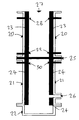
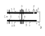
- U.S. Pat. No. 4,306,506 issued to F. Rotter describes a gasification apparatus consisting of a vertical cylindrical downdraft gasifier, in which the lower section is of double shell construction.
- gasification processes consisting of drying, distillation, oxidation and reduction occur.
- the bottom of the gasification section is comprised of a cone such that the local superficial velocity is increased to aid in heat and mass transfer.
- the syngas After passing through a grate the syngas is passed in an upward direction through the annulus created by the double shell construction.
- heat is transferred from the syngas exiting the system to the gasification processes occurring in the inner section, thus improving the thermal efficiency of the process and avoiding the need for an external heat exchange device.
- the biomass is partially combusted with oxygen, the heat of the combustion acts to fuel the endothermic reforming reactions which act to break down the remaining solid to produce the syngas.
- the biomass is contacted with superheated steam.
- the steam is either used in excess such that the required energy for the endothermic reactions is provided by the sensible heat contained in the steam or the process is externally heated.
- the syngas produced has a CO:H 2 ratio of approximately 1:1.
- syngas streams which are very rich in hydrogen are produced, syngas with a CO:H 2 as high as 1:9 has been achieved.
Abstract
Description
CH1.4O0.6+0.2O2=CO+0.7H2 (1)
However an energy balance across the Equation 1 reveals that the products contain more energy than the reactants, hence some of the biomass is burnt to offset this imbalance. Equation 1 illustrates how the typical ration of carbon monoxide to hydrogen is close to 1:1.
2H2+CO→CH3OH (2)
4H2+2CO→CH3CH2OH+H2O (3)
4H2+2CO→CH3OCH3+H2O (4)
2nH2 +nCO→n-CH2-+nH2O (5)
CO+H2O=CO2+H2 (6)
in which CO can be stoichiometrically interchanged with H2. This approach has been successfully used; however, the approach inevitably leads to a substantially mass loss of reactants, as carbon monoxide with a weight of 28 g/mol is used to produce hydrogen with a weight of 2 g/mol.
Claims (16)
Priority Applications (1)
| Application Number | Priority Date | Filing Date | Title |
|---|---|---|---|
| US12/471,198 US8043390B2 (en) | 2006-02-27 | 2009-05-22 | Apparatus and method for controlling the gas composition produced during the gasification of carbon containing feeds |
Applications Claiming Priority (3)
| Application Number | Priority Date | Filing Date | Title |
|---|---|---|---|
| US77716506P | 2006-02-27 | 2006-02-27 | |
| US11/678,981 US7569204B2 (en) | 2006-02-27 | 2007-02-26 | Apparatus and method for controlling the gas composition produced during the gasification of carbon containing feeds |
| US12/471,198 US8043390B2 (en) | 2006-02-27 | 2009-05-22 | Apparatus and method for controlling the gas composition produced during the gasification of carbon containing feeds |
Related Parent Applications (1)
| Application Number | Title | Priority Date | Filing Date |
|---|---|---|---|
| US11/678,981 Division US7569204B2 (en) | 2006-02-27 | 2007-02-26 | Apparatus and method for controlling the gas composition produced during the gasification of carbon containing feeds |
Publications (2)
| Publication Number | Publication Date |
|---|---|
| US20100098596A1 US20100098596A1 (en) | 2010-04-22 |
| US8043390B2 true US8043390B2 (en) | 2011-10-25 |
Family
ID=38459788
Family Applications (2)
| Application Number | Title | Priority Date | Filing Date |
|---|---|---|---|
| US11/678,981 Active - Reinstated US7569204B2 (en) | 2006-02-27 | 2007-02-26 | Apparatus and method for controlling the gas composition produced during the gasification of carbon containing feeds |
| US12/471,198 Expired - Fee Related US8043390B2 (en) | 2006-02-27 | 2009-05-22 | Apparatus and method for controlling the gas composition produced during the gasification of carbon containing feeds |
Family Applications Before (1)
| Application Number | Title | Priority Date | Filing Date |
|---|---|---|---|
| US11/678,981 Active - Reinstated US7569204B2 (en) | 2006-02-27 | 2007-02-26 | Apparatus and method for controlling the gas composition produced during the gasification of carbon containing feeds |
Country Status (5)
| Country | Link |
|---|---|
| US (2) | US7569204B2 (en) |
| EP (1) | EP1993368B1 (en) |
| BR (1) | BRPI0708721B1 (en) |
| MY (1) | MY140949A (en) |
| WO (1) | WO2007101186A2 (en) |
Cited By (1)
| Publication number | Priority date | Publication date | Assignee | Title |
|---|---|---|---|---|
| US20210363442A1 (en) * | 2016-03-04 | 2021-11-25 | Lummus Technology Llc | Two-stage gasifier and gasification process with feedstock flexibility |
Families Citing this family (13)
| Publication number | Priority date | Publication date | Assignee | Title |
|---|---|---|---|---|
| FR2905691B1 (en) * | 2006-09-13 | 2009-07-03 | Bio 3D Applic | METHOD FOR GENERATING AN ENERGY SOURCE FROM A WET GASEOUS FLOW |
| US8657892B2 (en) * | 2007-07-05 | 2014-02-25 | The Board Of Regents For Oklahoma State University | Downdraft gasifier with internal cyclonic combustion chamber |
| MX2007008317A (en) * | 2007-07-06 | 2009-02-26 | Aba Res Sa De Cv | Microwave gasification device. |
| US8309617B2 (en) * | 2009-12-31 | 2012-11-13 | Phillips 66 Company | Recycling methane-rich purge gas to gasifier |
| US20120021123A1 (en) | 2010-01-19 | 2012-01-26 | Leveson Philip D | process to sequester carbon, mercury, and other chemicals |
| US10059882B2 (en) | 2012-08-30 | 2018-08-28 | Earth Systems Consulting Pty Ltd | Efficient drying and pyrolysis of carbon-containing material |
| CA2899123C (en) * | 2013-01-28 | 2017-08-15 | PHG Energy, LLC | Method and device for gasifying feedstock |
| NZ712853A (en) * | 2013-03-01 | 2018-01-26 | John David Winter | Method and apparatus for processing carbonaceous material |
| US9376639B2 (en) * | 2013-03-15 | 2016-06-28 | Terrapower, Llc | Method and system for performing gasification of carbonaceous feedstock |
| US10144874B2 (en) | 2013-03-15 | 2018-12-04 | Terrapower, Llc | Method and system for performing thermochemical conversion of a carbonaceous feedstock to a reaction product |
| AU2014396195A1 (en) | 2014-06-02 | 2016-12-08 | PHG Energy, LLC | Microwave induced plasma cleaning device and method for producer gas |
| WO2018176026A1 (en) | 2017-03-24 | 2018-09-27 | Terrapower, Llc | Method and system for recycling pyrolysis tail gas through conversion into formic acid |
| US10787610B2 (en) | 2017-04-11 | 2020-09-29 | Terrapower, Llc | Flexible pyrolysis system and method |
Citations (19)
| Publication number | Priority date | Publication date | Assignee | Title |
|---|---|---|---|---|
| US3841239A (en) * | 1972-06-17 | 1974-10-15 | Shin Meiwa Ind Co Ltd | Method and apparatus for thermally decomposing refuse |
| US4004896A (en) | 1974-11-21 | 1977-01-25 | University Of Illinois Foundation | Production of water gas |
| US4146369A (en) * | 1976-09-07 | 1979-03-27 | Projektierung Chemische Verfahrenstechnik Gmbh | Process for gas production from solid fuels |
| US4306506A (en) | 1980-06-02 | 1981-12-22 | Energy Recovery Research Group, Inc. | Gasification apparatus |
| US4309195A (en) * | 1980-06-02 | 1982-01-05 | Energy Recovery Research Group, Inc. | Apparatus for gasifying solid fuels and wastes |
| US4417528A (en) * | 1982-09-29 | 1983-11-29 | Mansfield Carbon Products Inc. | Coal gasification process and apparatus |
| US4568271A (en) * | 1983-07-02 | 1986-02-04 | Kernforschungsanlage Julich Gesellschaft Mit Beschrankter Haftung | Method and shaft furnace for gasifying waste liquids containing organic components |
| US4583992A (en) | 1984-12-04 | 1986-04-22 | Buck Rogers Mfg. Co., Inc. | Biomass gasifier and charcoal producer |
| US4584947A (en) * | 1985-07-01 | 1986-04-29 | Chittick Donald E | Fuel gas-producing pyrolysis reactors |
| US4732091A (en) * | 1985-09-30 | 1988-03-22 | G.G.C., Inc. | Pyrolysis and combustion process and system |
| US4929254A (en) | 1989-07-13 | 1990-05-29 | Set Technology B.V. | Down-draft fixed bed gasifier system |
| US5226927A (en) * | 1991-02-13 | 1993-07-13 | Southern California Edison | Wood gasifier |
| US5554453A (en) | 1995-01-04 | 1996-09-10 | Energy Research Corporation | Carbonate fuel cell system with thermally integrated gasification |
| US20020069798A1 (en) * | 2000-09-14 | 2002-06-13 | Aguadas Ellis Charles W. | Method and apparatus for generating and utilizing combustible gas |
| US6615748B2 (en) * | 2000-10-20 | 2003-09-09 | Malahat Systems Corporation | Gasifier |
| US20040006917A1 (en) * | 2002-07-09 | 2004-01-15 | Wakefield David W. | Clean fuel gas made by the gasification of coal |
| US20040013605A1 (en) | 2002-07-16 | 2004-01-22 | Conoco Inc. | Controlling syngas H2:CO ratio by controlling feed hydrocarbon composition |
| US20040060236A1 (en) * | 2001-01-18 | 2004-04-01 | Kunio Yoshikawa | Apparatus for gasifying solid fuel |
| US20070261303A1 (en) * | 2006-05-12 | 2007-11-15 | Integrated Environmental Technologies, Llc | Combined gasification and vitrification system |
Family Cites Families (8)
| Publication number | Priority date | Publication date | Assignee | Title |
|---|---|---|---|---|
| US492954A (en) * | 1893-03-07 | Car-lamp | ||
| DE1017314B (en) * | 1953-10-09 | 1957-10-10 | Basf Ag | Process for the generation of fuel gases from dust-like to coarse-grained fuels |
| DE2947222A1 (en) * | 1979-11-23 | 1981-05-27 | Carbon Gas Technologie GmbH, 4030 Ratingen | METHOD FOR GASIFYING SOLID, DUST-MADE TO PIECE-LIKE CARBONATED MATERIAL |
| AU3058802A (en) * | 2000-12-04 | 2002-06-18 | Emery Recycling Corp | Multi-faceted gasifier and related methods |
| US6497187B2 (en) | 2001-03-16 | 2002-12-24 | Gas Technology Institute | Advanced NOX reduction for boilers |
| US20030083390A1 (en) * | 2001-10-23 | 2003-05-01 | Shah Lalit S. | Fischer-tropsch tail-gas utilization |
| DE10343582B4 (en) | 2003-09-18 | 2006-01-12 | Rwe Power Ag | Process and apparatus for fluidized bed gasification of solid carbonaceous materials with liquid slag removal |
| US6971323B2 (en) * | 2004-03-19 | 2005-12-06 | Peat International, Inc. | Method and apparatus for treating waste |
-
2007
- 2007-02-26 US US11/678,981 patent/US7569204B2/en active Active - Reinstated
- 2007-02-27 BR BRPI0708721A patent/BRPI0708721B1/en not_active IP Right Cessation
- 2007-02-27 EP EP07757532.2A patent/EP1993368B1/en not_active Not-in-force
- 2007-02-27 WO PCT/US2007/062861 patent/WO2007101186A2/en active Application Filing
-
2008
- 2008-08-07 MY MYPI20082995A patent/MY140949A/en unknown
-
2009
- 2009-05-22 US US12/471,198 patent/US8043390B2/en not_active Expired - Fee Related
Patent Citations (20)
| Publication number | Priority date | Publication date | Assignee | Title |
|---|---|---|---|---|
| US3841239A (en) * | 1972-06-17 | 1974-10-15 | Shin Meiwa Ind Co Ltd | Method and apparatus for thermally decomposing refuse |
| US4004896A (en) | 1974-11-21 | 1977-01-25 | University Of Illinois Foundation | Production of water gas |
| US4146369A (en) * | 1976-09-07 | 1979-03-27 | Projektierung Chemische Verfahrenstechnik Gmbh | Process for gas production from solid fuels |
| US4306506A (en) | 1980-06-02 | 1981-12-22 | Energy Recovery Research Group, Inc. | Gasification apparatus |
| US4309195A (en) * | 1980-06-02 | 1982-01-05 | Energy Recovery Research Group, Inc. | Apparatus for gasifying solid fuels and wastes |
| US4417528A (en) * | 1982-09-29 | 1983-11-29 | Mansfield Carbon Products Inc. | Coal gasification process and apparatus |
| US4568271A (en) * | 1983-07-02 | 1986-02-04 | Kernforschungsanlage Julich Gesellschaft Mit Beschrankter Haftung | Method and shaft furnace for gasifying waste liquids containing organic components |
| US4583992A (en) | 1984-12-04 | 1986-04-22 | Buck Rogers Mfg. Co., Inc. | Biomass gasifier and charcoal producer |
| US4584947A (en) * | 1985-07-01 | 1986-04-29 | Chittick Donald E | Fuel gas-producing pyrolysis reactors |
| US4732091A (en) * | 1985-09-30 | 1988-03-22 | G.G.C., Inc. | Pyrolysis and combustion process and system |
| US4929254A (en) | 1989-07-13 | 1990-05-29 | Set Technology B.V. | Down-draft fixed bed gasifier system |
| US5226927A (en) * | 1991-02-13 | 1993-07-13 | Southern California Edison | Wood gasifier |
| US5554453A (en) | 1995-01-04 | 1996-09-10 | Energy Research Corporation | Carbonate fuel cell system with thermally integrated gasification |
| US20020069798A1 (en) * | 2000-09-14 | 2002-06-13 | Aguadas Ellis Charles W. | Method and apparatus for generating and utilizing combustible gas |
| US6647903B2 (en) | 2000-09-14 | 2003-11-18 | Charles W. Aguadas Ellis | Method and apparatus for generating and utilizing combustible gas |
| US6615748B2 (en) * | 2000-10-20 | 2003-09-09 | Malahat Systems Corporation | Gasifier |
| US20040060236A1 (en) * | 2001-01-18 | 2004-04-01 | Kunio Yoshikawa | Apparatus for gasifying solid fuel |
| US20040006917A1 (en) * | 2002-07-09 | 2004-01-15 | Wakefield David W. | Clean fuel gas made by the gasification of coal |
| US20040013605A1 (en) | 2002-07-16 | 2004-01-22 | Conoco Inc. | Controlling syngas H2:CO ratio by controlling feed hydrocarbon composition |
| US20070261303A1 (en) * | 2006-05-12 | 2007-11-15 | Integrated Environmental Technologies, Llc | Combined gasification and vitrification system |
Non-Patent Citations (4)
| Title |
|---|
| Search Report for International Patent Application No. PCT/US2007/062861. |
| Spath et al; Preliminary Screening-Technical and Economic Assessment of Syntheses Gas to Fuels and Chemicals with . . . ; National Renewable Energy Laboratory; Dec. 2003; pp. 1-143. |
| Spath et al; Preliminary Screening—Technical and Economic Assessment of Syntheses Gas to Fuels and Chemicals with . . . ; National Renewable Energy Laboratory; Dec. 2003; pp. 1-143. |
| Zimmerman et al; On-line monitoring of traces of aromatic . . . (REMPI-TOFMS); Fresenius' Journal of Analytical Chemistry; Apr. 1999; vol. 363, No. 8, pp. 720-730 (Abstract only). |
Cited By (2)
| Publication number | Priority date | Publication date | Assignee | Title |
|---|---|---|---|---|
| US20210363442A1 (en) * | 2016-03-04 | 2021-11-25 | Lummus Technology Llc | Two-stage gasifier and gasification process with feedstock flexibility |
| US11639477B2 (en) * | 2016-03-04 | 2023-05-02 | Lummus Technology, Llc | Two-stage gasifier and gasification process with feedstock flexibility |
Also Published As
| Publication number | Publication date |
|---|---|
| MY140949A (en) | 2010-02-12 |
| BRPI0708721B1 (en) | 2016-08-02 |
| WO2007101186A3 (en) | 2007-12-21 |
| EP1993368B1 (en) | 2014-11-05 |
| BRPI0708721A2 (en) | 2011-06-07 |
| EP1993368A2 (en) | 2008-11-26 |
| US7569204B2 (en) | 2009-08-04 |
| BRPI0708721A8 (en) | 2015-10-06 |
| US20100098596A1 (en) | 2010-04-22 |
| EP1993368A4 (en) | 2013-01-09 |
| WO2007101186A2 (en) | 2007-09-07 |
| US20070270513A1 (en) | 2007-11-22 |
Similar Documents
| Publication | Publication Date | Title |
|---|---|---|
| US8043390B2 (en) | Apparatus and method for controlling the gas composition produced during the gasification of carbon containing feeds | |
| US9365784B2 (en) | Method of reducing oxygen requirement of a coal gasifier | |
| US8771387B2 (en) | Systems and methods for solar-thermal gasification of biomass | |
| US8574329B2 (en) | Method of operating a gasifier | |
| AU2002220288B2 (en) | Process and gas generator for generating fuel gas | |
| US20110078951A1 (en) | Two-stage high-temperature preheated steam gasifier | |
| EP3519537B1 (en) | Process for converting carbonaceous material into low tar synthesis gas | |
| KR101643792B1 (en) | Two stage dry feed gasification system and process | |
| CN103857772A (en) | Partial oxidation of methane and higher hydrocarbons in syngas streams | |
| KR20070085039A (en) | Process and apparatus for biomass gasification | |
| CN104937078B (en) | For the mixing arrangement of liquid fuel production and when the gasification unit in the mixing arrangement is in the method run under less than its designed productive capacity or while not running runs the mixing arrangement | |
| AU2011370246A1 (en) | Process for co-gasification of two or more carbonaceous feedstocks and apparatus thereof | |
| CA2184531C (en) | Method for producing hydrogen-carbon monoxide mixed gas, and apparatus thereof | |
| EP2199375A2 (en) | Multizone co-gasifier, method of operation thereof, and retrofit method | |
| US10982151B2 (en) | Process for converting carbonaceous material into low tar synthesis gas | |
| JP5380691B2 (en) | Biomass gasifier and method therefor | |
| WO2021191925A1 (en) | Gasification system design and process for reduction in tar formation | |
| US20230151285A1 (en) | Tar free cross flow gasification system for moisture containing feed |
Legal Events
| Date | Code | Title | Description |
|---|---|---|---|
| AS | Assignment |
Owner name: ZEROPOINT CLEAN TECH, INC.,NEW YORK Free format text: ASSIGNMENT OF ASSIGNORS INTEREST;ASSIGNOR:LEVESON, PHILIP D.;REEL/FRAME:023926/0782 Effective date: 20070604 Owner name: ZEROPOINT CLEAN TECH, INC., NEW YORK Free format text: ASSIGNMENT OF ASSIGNORS INTEREST;ASSIGNOR:LEVESON, PHILIP D.;REEL/FRAME:023926/0782 Effective date: 20070604 |
|
| STCF | Information on status: patent grant |
Free format text: PATENTED CASE |
|
| FPAY | Fee payment |
Year of fee payment: 4 |
|
| FEPP | Fee payment procedure |
Free format text: MAINTENANCE FEE REMINDER MAILED (ORIGINAL EVENT CODE: REM.); ENTITY STATUS OF PATENT OWNER: SMALL ENTITY |
|
| LAPS | Lapse for failure to pay maintenance fees |
Free format text: PATENT EXPIRED FOR FAILURE TO PAY MAINTENANCE FEES (ORIGINAL EVENT CODE: EXP.); ENTITY STATUS OF PATENT OWNER: SMALL ENTITY |
|
| STCH | Information on status: patent discontinuation |
Free format text: PATENT EXPIRED DUE TO NONPAYMENT OF MAINTENANCE FEES UNDER 37 CFR 1.362 |
|
| FP | Lapsed due to failure to pay maintenance fee |
Effective date: 20191025 |