US8040145B2 - Miniature fluid-cooled heat sink with integral heater - Google Patents
Miniature fluid-cooled heat sink with integral heater Download PDFInfo
- Publication number
- US8040145B2 US8040145B2 US12/625,154 US62515409A US8040145B2 US 8040145 B2 US8040145 B2 US 8040145B2 US 62515409 A US62515409 A US 62515409A US 8040145 B2 US8040145 B2 US 8040145B2
- Authority
- US
- United States
- Prior art keywords
- temperature control
- control device
- fluid
- heat sink
- flow
- Prior art date
- Legal status (The legal status is an assumption and is not a legal conclusion. Google has not performed a legal analysis and makes no representation as to the accuracy of the status listed.)
- Expired - Fee Related
Links
- 239000012530 fluid Substances 0.000 claims abstract description 126
- 239000002826 coolant Substances 0.000 claims abstract description 46
- 238000012360 testing method Methods 0.000 claims abstract description 32
- 238000001816 cooling Methods 0.000 claims description 34
- 238000012546 transfer Methods 0.000 abstract description 42
- 239000004065 semiconductor Substances 0.000 abstract description 6
- 239000010410 layer Substances 0.000 description 134
- AHCYMLUZIRLXAA-SHYZEUOFSA-N Deoxyuridine 5'-triphosphate Chemical compound O1[C@H](COP(O)(=O)OP(O)(=O)OP(O)(O)=O)[C@@H](O)C[C@@H]1N1C(=O)NC(=O)C=C1 AHCYMLUZIRLXAA-SHYZEUOFSA-N 0.000 description 18
- 239000000758 substrate Substances 0.000 description 12
- 238000013461 design Methods 0.000 description 9
- 238000010438 heat treatment Methods 0.000 description 8
- 239000000463 material Substances 0.000 description 8
- WYTGDNHDOZPMIW-RCBQFDQVSA-N alstonine Natural products C1=CC2=C3C=CC=CC3=NC2=C2N1C[C@H]1[C@H](C)OC=C(C(=O)OC)[C@H]1C2 WYTGDNHDOZPMIW-RCBQFDQVSA-N 0.000 description 6
- 239000000919 ceramic Substances 0.000 description 5
- 239000012809 cooling fluid Substances 0.000 description 5
- RYGMFSIKBFXOCR-UHFFFAOYSA-N Copper Chemical compound [Cu] RYGMFSIKBFXOCR-UHFFFAOYSA-N 0.000 description 4
- 229910052802 copper Inorganic materials 0.000 description 4
- 239000010949 copper Substances 0.000 description 4
- 230000001105 regulatory effect Effects 0.000 description 4
- 238000000034 method Methods 0.000 description 3
- 230000000704 physical effect Effects 0.000 description 3
- 230000004044 response Effects 0.000 description 3
- PXHVJJICTQNCMI-UHFFFAOYSA-N Nickel Chemical compound [Ni] PXHVJJICTQNCMI-UHFFFAOYSA-N 0.000 description 2
- 230000013011 mating Effects 0.000 description 2
- 229910052751 metal Inorganic materials 0.000 description 2
- 239000002184 metal Substances 0.000 description 2
- 238000012986 modification Methods 0.000 description 2
- 230000004048 modification Effects 0.000 description 2
- 238000012544 monitoring process Methods 0.000 description 2
- 229910052710 silicon Inorganic materials 0.000 description 2
- 239000010703 silicon Substances 0.000 description 2
- 230000007480 spreading Effects 0.000 description 2
- 238000003892 spreading Methods 0.000 description 2
- 238000010998 test method Methods 0.000 description 2
- 239000000853 adhesive Substances 0.000 description 1
- 230000001070 adhesive effect Effects 0.000 description 1
- 239000000956 alloy Substances 0.000 description 1
- 229910045601 alloy Inorganic materials 0.000 description 1
- 230000008901 benefit Effects 0.000 description 1
- 230000008859 change Effects 0.000 description 1
- 238000010344 co-firing Methods 0.000 description 1
- 239000012141 concentrate Substances 0.000 description 1
- 239000004020 conductor Substances 0.000 description 1
- 230000008602 contraction Effects 0.000 description 1
- 238000012937 correction Methods 0.000 description 1
- 230000008878 coupling Effects 0.000 description 1
- 238000010168 coupling process Methods 0.000 description 1
- 238000005859 coupling reaction Methods 0.000 description 1
- 230000007547 defect Effects 0.000 description 1
- 230000000694 effects Effects 0.000 description 1
- 230000005496 eutectics Effects 0.000 description 1
- 238000011990 functional testing Methods 0.000 description 1
- 238000005304 joining Methods 0.000 description 1
- 238000004519 manufacturing process Methods 0.000 description 1
- 239000011159 matrix material Substances 0.000 description 1
- 229910052759 nickel Inorganic materials 0.000 description 1
- 230000008569 process Effects 0.000 description 1
- 239000003507 refrigerant Substances 0.000 description 1
- 239000002356 single layer Substances 0.000 description 1
- 238000005476 soldering Methods 0.000 description 1
- 239000000126 substance Substances 0.000 description 1
- 238000012956 testing procedure Methods 0.000 description 1
- 239000002470 thermal conductor Substances 0.000 description 1
- WFKWXMTUELFFGS-UHFFFAOYSA-N tungsten Chemical compound [W] WFKWXMTUELFFGS-UHFFFAOYSA-N 0.000 description 1
- 229910052721 tungsten Inorganic materials 0.000 description 1
- 239000010937 tungsten Substances 0.000 description 1
- XLYOFNOQVPJJNP-UHFFFAOYSA-N water Substances O XLYOFNOQVPJJNP-UHFFFAOYSA-N 0.000 description 1
Images


Classifications
-
- H—ELECTRICITY
- H01—ELECTRIC ELEMENTS
- H01L—SEMICONDUCTOR DEVICES NOT COVERED BY CLASS H10
- H01L23/00—Details of semiconductor or other solid state devices
- H01L23/34—Arrangements for cooling, heating, ventilating or temperature compensation ; Temperature sensing arrangements
- H01L23/46—Arrangements for cooling, heating, ventilating or temperature compensation ; Temperature sensing arrangements involving the transfer of heat by flowing fluids
- H01L23/473—Arrangements for cooling, heating, ventilating or temperature compensation ; Temperature sensing arrangements involving the transfer of heat by flowing fluids by flowing liquids
-
- F—MECHANICAL ENGINEERING; LIGHTING; HEATING; WEAPONS; BLASTING
- F28—HEAT EXCHANGE IN GENERAL
- F28F—DETAILS OF HEAT-EXCHANGE AND HEAT-TRANSFER APPARATUS, OF GENERAL APPLICATION
- F28F3/00—Plate-like or laminated elements; Assemblies of plate-like or laminated elements
- F28F3/08—Elements constructed for building-up into stacks, e.g. capable of being taken apart for cleaning
- F28F3/086—Elements constructed for building-up into stacks, e.g. capable of being taken apart for cleaning having one or more openings therein forming tubular heat-exchange passages
-
- F—MECHANICAL ENGINEERING; LIGHTING; HEATING; WEAPONS; BLASTING
- F28—HEAT EXCHANGE IN GENERAL
- F28F—DETAILS OF HEAT-EXCHANGE AND HEAT-TRANSFER APPARATUS, OF GENERAL APPLICATION
- F28F2260/00—Heat exchangers or heat exchange elements having special size, e.g. microstructures
- F28F2260/02—Heat exchangers or heat exchange elements having special size, e.g. microstructures having microchannels
-
- H—ELECTRICITY
- H01—ELECTRIC ELEMENTS
- H01L—SEMICONDUCTOR DEVICES NOT COVERED BY CLASS H10
- H01L2924/00—Indexing scheme for arrangements or methods for connecting or disconnecting semiconductor or solid-state bodies as covered by H01L24/00
- H01L2924/0001—Technical content checked by a classifier
- H01L2924/0002—Not covered by any one of groups H01L24/00, H01L24/00 and H01L2224/00
Definitions
- the present invention relates generally to a temperature control device that controls the temperature of an electronic device during testing. More particularly, the present invention relates to a miniature liquid-cooled heat sink with integral heater and sensing elements for maintaining constant operating temperature of the electronic device under test.
- Electronic devices such as integrated circuit chips, are usually tested prior to use.
- Device manufacturers typically perform a number of electrical and physical tests to ensure that the devices are free from defects and that the devices function according to their specifications.
- Common types of device testing include burn-in testing and electrical performance testing.
- the operating temperature of an electronic device under test is an important test parameter that usually requires careful monitoring and/or regulating.
- an electrical test procedure may designate a number of specific test temperatures or a specific range of test temperatures. Consequently, the prior art is replete with different types of temperature control systems, heat sink components, and heater elements designed to heat, cool, and otherwise control the operating temperature of a DUT. These temperature control systems are designed to maintain a steady state DUT operating temperature during the electronic testing procedure.
- it can be difficult to regulate the temperature of a DUT if the DUT exhibits rapid or excessive internal temperature changes while being tested; the electronic devices within the DUT often generate heat which causes such internal temperature changes.
- the prior art configurations may not be capable of efficiently and effectively compensating for rapid temperature fluctuations generated by the DUT.
- a preferred embodiment of the present invention is realized as a temperature control device that includes a miniature fluid-cooled heat sink with integral heater and sensing elements.
- the device may be used as part of a temperature control system to provide a controlled temperature surface to an electronic DUT, such as a semiconductor device, during the testing phase.
- the liquid-cooled heat sink includes two internal cooling passages with inlets, outlets and heat transfer portions. The heat transfer portions are located on separate planes and may include cooling fins.
- a temperature control device includes a fluid-cooled heat sink structure configured to maintain a cross-flow of coolant in three-dimensions for the cooling of a DUT interface surface.
- the heat sink structure may employ a three-dimensional microchannel structure that directs coolant flow in three dimensions within a respective fluid conduit.
- FIG. 1 is an isometric view of a temperature control device for regulating the temperature of a device under test
- FIG. 2 is an exploded perspective view of the temperature control device of FIG. 1 , showing the cooling layers and passages;
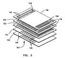
- FIGS. 3-5 are exploded perspective views of various temperature control devices, showing the heater layer positions in relation to the cooling layers;
- FIG. 6 is a perspective view of a temperature control device, showing the DUT interface surface side
- FIG. 7 is a perspective view of the temperature control device shown in FIG. 6 , showing the fluid entry/exit side;
- FIG. 8 is an exploded perspective view of the temperature control device shown in FIGS. 6 and 7 ;
- FIG. 9 is a top view of one of the outer layers of the temperature control device shown in FIG. 8 ;
- FIG. 10 is a top view of one of the internal layers of the temperature control device shown in FIG. 8 ;
- FIG. 11 is a schematic perspective view of an example microchannel structure that may be formed within the temperature control device shown in FIGS. 6 and 7 .
- a temperature control device configured in accordance with the invention employs a fluid-cooled heat sink structure that maintains a cross-flow of coolant in three dimensions for cooling a DUT interface surface of the temperature control device.
- the heat sink structure includes at least two layered heat transfer portions that establish the three-dimensional coolant flow.
- the heat sink structure includes a microchannel structure that forces the coolant to flow in three dimensions within a fluid conduit or channel. Other practical embodiments may also fall within the scope and spirit of the invention.
- a miniature fluid-cooled heat sink with integral heater and sensing elements is used as part of a temperature control system to provide a controlled temperature surface to an electronic device, such as a semiconductor device, during the testing phase.
- the semiconductor device is placed either directly in contact with the device or with an interface material or area-adapting heat spreader, such as a metal plate, while in use.
- the integral heating element is used to heat itself and the device to a set temperature
- the sensing elements detect the temperature
- the coolant flowing through the heat sink removes excess heat from the device.
- a practical temperature control device can be designed to accommodate test temperatures between ⁇ 55 and 155 degrees Celsius. However, most electronic devices are typically tested at temperatures between ⁇ 45 and 120 degrees Celsius (these example temperature ranges may change in the future and the invention disclosed is not limited to any specific range of test temperatures). In addition, electronic device test specifications do not usually call for temperature transients, i.e., most electronic testing is performed at a substantially steady state operating temperature.
- One advantage of the devices described herein is that their compact size, low thermal mass, and electronic heating allow very rapid corrections to deviations from the setpoint temperature.
- the integral nature of the temperature control devices simplifies the design and requires no subsequent assembly. Once assembled, the monolithic nature of the devices, which use thermally conductive materials, ensures that the fluid channel will effectively and repeatably remove heat.
- FIG. 1 is a perspective view of one embodiment of a temperature control device 100 used for regulating the temperature of a DUT 102 .
- DUT 102 is an electronic semiconductor circuit device, such as a microprocessor chip.
- DUT 102 may be any electronic, mechanical, or other device being subjected to one or more tests performed under specific temperature settings.
- the temperature control device 100 may cooperate with a suitable testing system (not shown) that provides a power supply, coolant flow control, input signals, and possibly other inputs to DUT 102 .
- a typical testing system also monitors a number of outputs and signals generated by DUT 102 during the test procedure.
- the temperature control device 100 is designed to provide a controlled temperature at an interface surface or first side 103 that provides a thermal path from the temperature control device 100 to the DUT 102 .
- the DUT 102 is preferably held against or in close proximity to interface surface 103 of the temperature control device 100 .
- Inside the temperature control device 100 are internal cooling passages, integral heaters, and sensing elements. To regulate the temperature at the interface surface 103 , the integral heaters are turned on to provide heat and a fluid is directed through the cooling passages to provide cooling. The subsequent figures and text will describe the cooling passages and integral heater layers and their locations.
- the temperature control device 100 may be regulated by a suitably configured control system 101 .
- the sensing elements are used to provide input to the control system to monitor the temperature of the temperature control device 100 and determine when it should be heated or cooled.
- the control system 101 generates a control signal that serves as an input signal to the integral heater and/or cooling system contained in temperature control device 100 .
- the control signal may be generated by control system 101 in response to one or more testing criteria, operating conditions, or feedback signals.
- control system 101 may generate a control signal in response to any of the following parameters: a test temperature setting associated with the current testing specification for DUT 102 ; an input signal utilized by DUT 102 , e.g., an input power signal, an input voltage, or an input current; a signal indicative of the real-time operating temperature of DUT 102 ; a signal indicative of the real-time operating temperature of an internal component of DUT 102 , e.g., a semiconductor die; a signal indicative of the real-time temperature of a portion of temperature control device 100 ; the RF signature of DUT 102 ; or the like.
- a test temperature setting associated with the current testing specification for DUT 102
- an input signal utilized by DUT 102 e.g., an input power signal, an input voltage, or an input current
- a signal indicative of the real-time operating temperature of DUT 102 e.g., a signal indicative of the real-time operating temperature of an internal component of DUT 102 , e.g.,
- a fluid is passed through a first internal cooling passage 104 and a second internal cooling passage 106 (see FIG. 2 ).
- the fluid may be water, air, a refrigerant, or any fluid substance having the desired thermal properties.
- the first internal cooling passage 104 has an inlet 108 and an outlet 109 .
- the second internal cooling passage 106 has an inlet 110 and an outlet 111 .
- a first fluid 112 A enters through the first inlet 108 and the fluid 112 B exits through the first outlet 109 .
- the second fluid 114 A enters through the second inlet 110 and the second fluid 114 B exits through the second outlet 111 .
- the fluid travels through the internal passages 104 and 106 , cooling the temperature control device 100 .
- a coolant system (not shown) may provide the fluid 112 and 114 and cooperate with temperature control device 100 to regulate the temperature and flow rate of the fluid.
- the coolant system pumps the fluid into temperature control device 100 through the inlets 108 and 110 , and receives the return fluid from the outlets 109 and 111 .
- the inlet and outlet ports may be designed with internal threads such that suitable fluid fittings (not shown) can be attached.
- the fluid fittings receive fluid delivery hoses or conduits that carry the fluid between the temperature control device 100 and coolant system.
- FIG. 2 is an exploded view showing some of the layers of the cooling portion of the temperature control device 100 .
- the cooling portion includes two cooling passages 104 and 106 that go through the temperature control device 100 .
- Each cooling passage has an inlet, an outlet, and a heat transfer portion or layer that create a continuous fluid conduit through the device.
- the inlets and outlets are positioned in the cover layer 116 , which may include one or more layers depending on the design.
- the cover layer 116 shown in FIG. 2 has multiple layers 116 A, 116 B and 116 C that provide channels and passages to direct the fluid flow to the other layers and keep each of the fluid passages separate.
- the flow of the fluid paths through the cooling passages 104 and 106 are shown in FIG. 2 .
- the first cooling passage 104 starts at the first inlet 108 , in cover layer 116 A, opening to a passage on layer 116 B that leads to a fluid opening 118 A at a first end of the layer 116 B. There may be subsequent fluid openings 118 , depending on the number of layers and the position of the first heat transfer portion or layer. In the figure shown, there is a fluid opening 118 B in layer 116 C and a fluid opening 118 C in layer 120 that leads to a first heat transfer portion or layer 122 .
- the first heat transfer portion or layer 122 is designed such that fluid enters near a first end, travels across the layer, through various openings or passages, to a second end, where it exits the layer 122 .
- the fluid passage continues to a fluid opening 119 C in layer 120 , a fluid opening 119 B in layer 116 C, to a fluid opening 119 A in layer 116 B, which finally leads to the first outlet 109 .
- the second cooling passage 106 starts at the second inlet 110 in cover layer 116 A, opening to a passage 124 through a layer 116 B that leads to a passage in layer 116 C that leads to a fluid opening 126 , near fluid opening 199 B in layer 116 C. There may be subsequent fluid openings 126 , depending on the number of layers and the position of the first heat transfer portion or layer. In the figure shown, the fluid opening 126 leads to a second heat transfer portion or layer 120 .
- the second heat transfer portion or layer 120 is designed such that fluid enters near a first end, travels across the layer, through various openings or passages to a second end, where it exits the layer 120 .
- the fluid passage 106 leads a to fluid opening 128 in layer 116 C, to a fluid opening 130 in layer 116 B, which leads to the second outlet 111 .
- the fluid can flow in either direction in the cooling passages, but for enhanced performance, the fluid should flow in opposite directions in each passage.
- One goal of this design is to reduce the surface temperature gradient of the temperature control device 100 .
- the first heat transfer portion 122 resides in a first plane and the second heat transfer portion 120 resides in a second plane, where the first plane is closer to the interface surface 103 than the second plane.
- the two planes are parallel to each other, as depicted in FIG. 2 .
- This stacked arrangement facilitates a cross-flow of coolant in three dimensions.
- two heat transfer layers are shown in the figures, a practical implementation may employ any number of heat transfer layers, whether directly stacked upon each other or separated by one or more other elements.
- FIGS. 3-5 show examples of some positions where the integral heater layers may be located within the temperature control device 100 .
- the cover layer 116 is shown as a single layer, but may have multiple layers, as described above.
- the heater layers 132 and 134 may be made of electrically resistive serpentine traces 138 on a substrate having external connections 136 connected to a controller 101 .
- the substrate may be made from silicon, ceramic or other appropriate material.
- the resistive traces 138 may provide uniform heating or may be arranged to provide differential heating with differential control.
- FIG. 3 there may be fluid openings for fluid passages 104 and 106 in the heater layers.
- the heater layers 132 and 134 are shown proximate the interface surface 103 , such that the heat transfer layers 120 and 122 are positioned between the heater layers 132 and 134 and the cover layer 116 . Since the heater layers 132 and 134 are positioned away from the cover layer 116 and heat transfer layers 120 and 122 , there are no fluid openings required through the heater layers.
- FIG. 4 the heat transfer layers 120 and 122 are proximate the interface surface 103 and the heater layers 132 and 134 are positioned between the heat transfer layers 120 and 122 and the cover layer 116 .
- the heater layers 132 and 134 are positioned between the cover layer 116 and the heat transfer layers 120 and 122 , there are fluid openings 118 and 128 through the heater layers 132 and 134 near a first end, and fluid openings 119 and 126 through them near a second end as part of the fluid passages 104 and 106 .
- the electrically resistive serpentine traces 138 are positioned on each heater layer 132 and 134 between the fluid openings.
- the heater layer 132 is proximate the interface surface 103 and the heater layer 134 is proximate the cover layer 116 .
- the heat transfer layers 120 and 122 are positioned between the heater layers 132 and 134 .
- the heater layer 134 is positioned between the cover layer 116 and the heat transfer layers 120 and 122 , there are fluid openings 118 and 128 through the heater layer 134 near a first end, and fluid openings 119 and 126 through it near a second end as part of the fluid passages 104 and 106 .
- the electrically resistive serpentine trace 138 is positioned on the heater layer 134 between the fluid openings.
- One or more sensing elements are included in the temperature control device 100 .
- the sensing elements are connected to the control system or other means of monitoring the sensor readings.
- the sensing elements may be used to indicate the temperatures at one or more locations in the temperature control device 100 .
- the sensors may monitor the interface surface 103 temperature, the heater layer 132 and 134 temperatures (separately or combined), the fluid temperatures or heat transfer layer temperature (separately or combined) and other places where sensing may be appropriate or desired.
- temperature control device 100 may thermally condition the DUT 102 by providing a controlled thermal surface 103 to the DUT 102 during a testing phase.
- the DUT 102 is placed either directly in contact with the device or uses an interface material or area-adapting heat spreader, such as a metal plate, while in use.
- the DUT 102 is then subjected to the functional testing as required by the test specification.
- the control system 101 or test equipment, monitors the temperature of DUT 102 during the functional test and regulates the temperature of the heating and cooling elements associated with temperature control device 100 .
- the integral heater layers 132 and 134 may be turned on and off, either together or separately, with varying power levels, to heat the device, and cooling fluid flows through the fluid passages 104 and 106 to cool the device.
- the temperature of each heating element is independently controlled by adjusting the respective power applied to the element.
- the temperature control device 100 is configured to heat or cool the DUT by providing a direct thermal path to the DUT.
- the thermal path to the DUT is from the controlled thermal interface surface 103 to the cover layer(s) 116 .
- the thermal path includes the first heater layer 132 , the second heater layer 134 , the first heat transfer layer 122 and the second heat transfer layer 120 .
- the thermal path includes the first heat transfer layer 122 , the second heat transfer layer 120 the first heater layer 132 and the second heater layer 134 .
- the thermal path includes the first heater layer 132 , first heat transfer layer 122 , the second heat transfer layer 120 and the second heater layer 134 .
- the size and shape of the controlled thermal interface surface 103 of the temperature control device 100 may be suitably configured to mate with the size and shape of the particular DUT.
- the size of the device may be 1 inch wide by 2 inches long and 0.25 inches thick (other sizes and shapes can be employed to accommodate the particular application).
- a suitably configured mating element formed from a thermal conductor, can be placed between temperature control device 100 and the DUT 102 .
- a mating element may be desirable to accommodate the specific physical characteristics of the DUT or to concentrate heating or cooling in certain areas of the DUT.
- the heat transfer layers 120 and 122 may include a number of cooling fins that are configured and arranged to promote heat transfer from to the fluid or coolant.
- the plurality of parallel cooling fins are also parallel to the fluid flow path in the heat transfer layers 120 and 122 .
- each of the cooling fins is approximately 0.012 inches thick.
- neighboring cooling fins are separated by approximately 0.012 inches.
- the heat transfer layers may employ any suitable cooling fin design and the particular design may depend on any number of parameters such as the thermal properties of the heat sink material, the thermal and physical properties of the coolant, the flow rate of the coolant, the size of heat transfer layers, and the like.
- Electrically conductive “ink” may be used to form the electrically resistive serpentine traces 138 on the substrate.
- the conductive ink includes a nickel, tungsten, or other alloy having a relatively high electrical resistance.
- the substrate is patterned and the conductive ink is printed onto the surface of the substrate, which might then be joined to additional layers by stacking.
- Signal wires or leads 136 are soldered or otherwise attached to the respective traces to carry the respective heater control signals from the control system.
- the electrical heating elements traces are not exposed to the DUT.
- the temperature control device 100 Numerous methods of manufacture may be used to construct the temperature control device 100 .
- all of the layer substrates are manufactured in a “green” ceramic state, then once the fluid channels, electrically resistive metallic serpentine traces, sensors and connections have been formed on the substrates, the layers are joined by co-firing forming a monolithic type structure.
- the layer substrates are silicon and once the fluid channels, electrically resistive metallic serpentine traces, sensors and connections have been formed on the substrates, the layers are joined by eutectic bonding, or other high-thermal-conductivity joining process.
- FIGS. 6-11 show various views of another temperature control device 200 configured in accordance with the invention.
- the device 200 generally includes an interface surface 202 configured to provide a thermal path to a DUT, a fluid-cooled heat sink structure 204 configured to maintain a cross-flow of coolant in three dimensions for cooling interface surface 202 ; and a heater assembly 206 configured to heat interface surface 202 .
- Heater assembly 206 may be configured as described above in connection with device 100 .
- Heater assembly 206 includes one or more electrical heater elements coupled to a substrate.
- heater assembly 206 may include a number of terminals or contact points (hidden from view) that accommodate one or more heater control signals.
- the control signals are fed through holes in the heat sink en route to the terminals on heater assembly 206 .
- interface surface 202 is held against a DUT (not shown), heater assembly 206 is controlled to regulate heat applied to the DUT, and coolant is passed through heat sink structure 204 to regulate the temperature of the DUT.
- the flow rate and/or temperature of the coolant can be controlled by a coolant flow control system (not shown) coupled to the device 200 .
- device 200 includes one or more fluid inlets 210 and one or more fluid outlets 212 formed therein to accommodate the flow of coolant.
- fluid coupling elements for the inlets 210 and outlets 212 are not shown in connection with device 200 .
- Temperature control device 200 is preferably formed from a plurality of layers, as best shown in FIG. 8 .
- the illustrated embodiment includes heater assembly 206 , a first cover layer 214 , a first intermediate layer 216 , a plurality of microchannel layers 218 , a second intermediate layer 220 having fluid inlets and fluid outlets formed therein, and a second cover layer 222 having fluid inlets and fluid outlets formed therein.
- the various layers are coupled together using one or more known techniques such as bonding, soldering, adhesive, or the like. After the stack is constructed, the fluid inlets and outlets formed in second intermediate layer 220 and second cover layer 222 form fluid inlets 210 and fluid outlets 212 .
- first cover layer 214 is formed from copper
- first intermediate layer 216 is formed from a ceramic substrate material
- each of the microchannel layers 218 is formed from copper
- second intermediate layer 220 is formed from a ceramic substrate material
- second cover layer 222 is formed from copper.
- First and second intermediate layers 216 and 220 function to “isolate” the effects of thermal expansion and contraction of the copper layers from heater assembly 206 (which, in the example embodiment, is ceramic based).
- the layers are coupled together in a manner that forms fluid seals such that the cooling fluid is maintained in the proper channels and flow paths within heat sink structure 204 .
- heat sink structure 204 is formed such that (ideally) the cooling fluid can only enter through fluid inlets 210 and only exit through fluid outlets 212 .
- each of the microchannel layers 218 includes ribs 224 that separate adjacent fluid conduits 226 from one another.
- the microchannel layer 218 shown in FIG. 10 includes seven ribs 224 and eight conduits 226 .
- ribs 224 form “walls” between adjacent conduits 226 .
- ribs 224 are each approximately 0.020 inches wide, each conduit 226 is approximately 1.850 inches long, and (after stacking) heat sink structure is approximately 0.158 inches thick. Of course, these dimensions can vary to accommodate different applications and different DUT sizes.
- Temperature control device 200 is suitably configured to establish a cross-flow of coolant within heat sink structure 204 .
- fluid conduits 226 are coplanar and parallel.
- one subset of the fluid conduits 226 accommodate coolant flow in a first direction while another subset of the fluid conduits 226 accommodate coolant flow in a second direction.
- the first direction is opposite to the second direction.
- device 200 maintains the coolant cross-flow by directing the coolant into certain fluid inlets 210 .
- fluid inlets 210 a - d which respectively correspond to fluid outlets 212 a - d , accommodate coolant flow in a first direction (from the top to the bottom of FIG. 9 ).
- fluid inlets 210 e - h which respectively correspond to fluid outlets 212 e - h , accommodate coolant flow in a second direction (from the bottom to the top of FIG. 9 ).
- This flow pattern results in a different flow direction in adjacent conduits 226 .
- the coolant cross-flow reduces the thermal gradient over the interface surface 206 and results in more efficient temperature regulation of the DUT.
- Each microchannel layer 218 also includes a web, mesh, matrix, lattice, or similar structure 228 located within the fluid conduits 226 .
- the web structure 228 may employ a geometric pattern, e.g., squares, triangles, circles, hexagons, octagons, or the like. As shown in FIG. 11 , the example embodiment employs a lattice of hexagons for web structure 228 .
- the web structure 228 in each microchannel layer 218 is planar or flat such that only one “level” of hexagons reside in each microchannel layer 218 .
- the web structure 228 in adjacent stacked microchannel layers 218 is staggered or offset such that, when heat sink structure 204 is formed, the web structures 228 create respective three-dimensional microchannel structures located within the various fluid conduits 226 .
- FIG. 11 depicts three offset web structures 228 forming such a three-dimensional microchannel structure.
- the resulting three-dimensional microchannel structures are configured to direct coolant flow in three dimensions within each fluid conduit. Due to the offset nature of the individual web structures 228 , the coolant will flow laterally through the three-dimensional microchannel structure while flowing vertically over and under the individual web structure levels.
- the individual web structures 228 may be arranged and coupled together such that continuous heat transfer paths are formed from the top to the bottom of heat sink structure 204 , thus improving the heat transfer efficiency.
- fluid conduits 226 and respective microchannel structures are adjacent to one another.
- a first subset of fluid conduits are located at one layer
- a second subset of fluid conduits are located at a second layer below the first layer
- both groups of fluid conduits are located above interface surface 206 .
- Coolant cross-flow may be established in the manner described above and/or by directing coolant in one direction through the first subset of fluid conduits and in a second direction through the second subset of fluid conduits.
- the layered design of these devices allows the flexibility to tailor the heat sink efficiency and the pressure drop across the heat sink by simply changing the number of layers. In this regard, more layers results in higher heat sink efficiency to remove heat, which in turn results in a better response time for an active thermal control system. Additional layers also results in lower pressure drop as the cooling fluid flows across the heat sink. Lower pressure drop results in a lower cooling fluid inlet pressure requirement, which is desirable for practical applications. Additional layers also results in higher thermal mass for the heat sink. Consequently, the layered heat sink design facilitates rapid cost effective provisioning of an optimized device for the given application by allowing the designer to strike a balance between thermal efficiency and thermal mass.
Abstract
Description
Claims (15)
Priority Applications (1)
| Application Number | Priority Date | Filing Date | Title |
|---|---|---|---|
| US12/625,154 US8040145B2 (en) | 2004-02-23 | 2009-11-24 | Miniature fluid-cooled heat sink with integral heater |
Applications Claiming Priority (3)
| Application Number | Priority Date | Filing Date | Title |
|---|---|---|---|
| US10/785,204 US20050189342A1 (en) | 2004-02-23 | 2004-02-23 | Miniature fluid-cooled heat sink with integral heater |
| US11/326,340 US7626407B2 (en) | 2004-02-23 | 2006-01-06 | Miniature fluid-cooled heat sink with integral heater |
| US12/625,154 US8040145B2 (en) | 2004-02-23 | 2009-11-24 | Miniature fluid-cooled heat sink with integral heater |
Related Parent Applications (1)
| Application Number | Title | Priority Date | Filing Date |
|---|---|---|---|
| US11/326,340 Division US7626407B2 (en) | 2004-02-23 | 2006-01-06 | Miniature fluid-cooled heat sink with integral heater |
Publications (2)
| Publication Number | Publication Date |
|---|---|
| US20100066399A1 US20100066399A1 (en) | 2010-03-18 |
| US8040145B2 true US8040145B2 (en) | 2011-10-18 |
Family
ID=34886641
Family Applications (3)
| Application Number | Title | Priority Date | Filing Date |
|---|---|---|---|
| US10/785,204 Abandoned US20050189342A1 (en) | 2004-02-23 | 2004-02-23 | Miniature fluid-cooled heat sink with integral heater |
| US11/326,340 Expired - Fee Related US7626407B2 (en) | 2004-02-23 | 2006-01-06 | Miniature fluid-cooled heat sink with integral heater |
| US12/625,154 Expired - Fee Related US8040145B2 (en) | 2004-02-23 | 2009-11-24 | Miniature fluid-cooled heat sink with integral heater |
Family Applications Before (2)
| Application Number | Title | Priority Date | Filing Date |
|---|---|---|---|
| US10/785,204 Abandoned US20050189342A1 (en) | 2004-02-23 | 2004-02-23 | Miniature fluid-cooled heat sink with integral heater |
| US11/326,340 Expired - Fee Related US7626407B2 (en) | 2004-02-23 | 2006-01-06 | Miniature fluid-cooled heat sink with integral heater |
Country Status (4)
| Country | Link |
|---|---|
| US (3) | US20050189342A1 (en) |
| JP (1) | JP2007534937A (en) |
| DE (1) | DE112005000414T5 (en) |
| WO (1) | WO2005081947A2 (en) |
Cited By (2)
| Publication number | Priority date | Publication date | Assignee | Title |
|---|---|---|---|---|
| US20090323285A1 (en) * | 2008-06-25 | 2009-12-31 | Sony Corporation | Heat transport device and electronic apparatus |
| US9835649B1 (en) * | 2014-06-26 | 2017-12-05 | Vektrex Electronic Systems, Inc. | Reconfigurable LED load board clamp |
Families Citing this family (60)
| Publication number | Priority date | Publication date | Assignee | Title |
|---|---|---|---|---|
| US7218129B2 (en) * | 2005-01-12 | 2007-05-15 | International Business Machines Corporation | System, apparatus and method for controlling temperature of an integrated circuit under test |
| US7391320B1 (en) | 2005-04-01 | 2008-06-24 | Horizon Hobby, Inc. | Method and system for controlling radio controlled devices |
| US7663227B2 (en) * | 2005-10-11 | 2010-02-16 | Macris Chris G | Liquid metal thermal interface material system |
| WO2008024821A2 (en) * | 2006-08-22 | 2008-02-28 | Brilliant Telecommunications, Inc. | Apparatus and method for thermal stabilization of pcb-mounted electronic components within an enclosed housing |
| US20080047688A1 (en) * | 2006-08-28 | 2008-02-28 | Airbus Deutschland Gmbh | Cooling System And Cooling Method For Cooling Components Of A Power Electronics |
| US8056615B2 (en) * | 2007-01-17 | 2011-11-15 | Hamilton Sundstrand Corporation | Evaporative compact high intensity cooler |
| EP2061078B1 (en) * | 2007-11-16 | 2015-07-15 | IQ evolution GmbH | Cooling element |
| US20090151893A1 (en) * | 2007-12-13 | 2009-06-18 | International Business Machines Corporation | High performance compliant thermal interface cooling structures |
| US9157687B2 (en) * | 2007-12-28 | 2015-10-13 | Qcip Holdings, Llc | Heat pipes incorporating microchannel heat exchangers |
| BRPI0923789B8 (en) | 2008-12-30 | 2021-06-22 | Ultradent Products Inc | dental healing light having unique body design that acts as a heat sink |
| DE102009000514A1 (en) | 2009-01-30 | 2010-08-26 | Robert Bosch Gmbh | Composite component and method for producing a composite component |
| US20100200197A1 (en) * | 2009-02-09 | 2010-08-12 | International Business Machines Corporation | Liquid cooled compliant heat sink and related method |
| US8400178B2 (en) * | 2009-04-29 | 2013-03-19 | Taiwan Semiconductor Manufacturing Company, Ltd. | Method and system of testing a semiconductor device |
| US9347987B2 (en) * | 2009-11-06 | 2016-05-24 | Intel Corporation | Direct liquid-contact micro-channel heat transfer devices, methods of temperature control for semiconductive devices, and processes of forming same |
| US8779793B2 (en) * | 2010-03-03 | 2014-07-15 | Nvidia Corporation | System and method for temperature cycling |
| US20120012299A1 (en) * | 2010-07-16 | 2012-01-19 | Industrial Idea Partners, Inc. | Proportional Micro-Valve With Thermal Feedback |
| US8899052B2 (en) | 2010-11-04 | 2014-12-02 | International Business Machines Corporation | Thermoelectric-enhanced, refrigeration cooling of an electronic component |
| US8813515B2 (en) | 2010-11-04 | 2014-08-26 | International Business Machines Corporation | Thermoelectric-enhanced, vapor-compression refrigeration apparatus facilitating cooling of an electronic component |
| US8955346B2 (en) | 2010-11-04 | 2015-02-17 | International Business Machines Corporation | Coolant-buffered, vapor-compression refrigeration apparatus and method with controlled coolant heat load |
| US8833096B2 (en) | 2010-11-04 | 2014-09-16 | International Business Machines Corporation | Heat exchange assembly with integrated heater |
| US8783052B2 (en) | 2010-11-04 | 2014-07-22 | International Business Machines Corporation | Coolant-buffered, vapor-compression refrigeration with thermal storage and compressor cycling |
| US20120111038A1 (en) | 2010-11-04 | 2012-05-10 | International Business Machines Corporation | Vapor-compression refrigeration apparatus with backup air-cooled heat sink and auxiliary refrigerant heater |
| JP5946476B2 (en) * | 2011-03-07 | 2016-07-06 | アアヴィッド・サーマロイ・エルエルシー | Heat transfer device with helical fluid path |
| US20130056176A1 (en) * | 2011-08-26 | 2013-03-07 | Mikros Manufacturing, Inc. | Heat Exchanger with Controlled Coefficient of Thermal Expansion |
| US8814425B1 (en) * | 2011-09-30 | 2014-08-26 | Emc Corporation | Power measurement transducer |
| US8814424B1 (en) * | 2011-09-30 | 2014-08-26 | Emc Corporation | Power measurement transducer |
| US9207002B2 (en) | 2011-10-12 | 2015-12-08 | International Business Machines Corporation | Contaminant separator for a vapor-compression refrigeration apparatus |
| DE102012106244B4 (en) * | 2012-07-11 | 2020-02-20 | Rogers Germany Gmbh | Metal-ceramic substrate |
| US20160282059A1 (en) * | 2013-03-18 | 2016-09-29 | Mahle International Gmbh | Layered heat transfer device and method for producing a layered heat transfer device |
| US9526191B2 (en) * | 2013-05-15 | 2016-12-20 | Dy 4 Systems Inc. | Fluid cooled enclosure for circuit module apparatus and methods of cooling a conduction cooled circuit module |
| TWI639011B (en) * | 2015-02-13 | 2018-10-21 | 日商精工愛普生股份有限公司 | Electronic component conveying device and electronic component inspection device |
| JP2016148610A (en) * | 2015-02-13 | 2016-08-18 | セイコーエプソン株式会社 | Electronic component conveyance device and electronic component inspection device |
| DE102015009603B4 (en) * | 2015-07-24 | 2019-05-09 | Te Connectivity Germany Gmbh | DEVICE FOR MEASURING AN ELECTRIC CURRENT THROUGH A CIRCUIT |
| CN107924898B (en) * | 2015-09-18 | 2020-10-27 | 株式会社T.Rad | Laminated radiator |
| EP3352215B1 (en) * | 2015-09-18 | 2021-08-25 | T.RAD Co., Ltd. | Laminated core type heat sink |
| US9977072B2 (en) * | 2015-11-30 | 2018-05-22 | Taiwan Semiconductor Manufacturing Company Ltd. | Semiconductor structure and method for operating the same |
| EP3446059A4 (en) * | 2016-04-18 | 2020-01-01 | Oregon State University | Laminated microchannel heat exchangers |
| US11732978B2 (en) | 2016-04-18 | 2023-08-22 | Qcip Holdings, Llc | Laminated microchannel heat exchangers |
| US20180172041A1 (en) * | 2016-12-20 | 2018-06-21 | Baker Hughes Incorporated | Temperature regulated components having cooling channels and method |
| US10782316B2 (en) | 2017-01-09 | 2020-09-22 | Delta Design, Inc. | Socket side thermal system |
| US20190212066A1 (en) * | 2018-01-11 | 2019-07-11 | Asia Vital Components Co., Ltd. | Water-cooling radiator assembly with internal horiziontal partition members and flow disturbing members |
| US11493551B2 (en) | 2020-06-22 | 2022-11-08 | Advantest Test Solutions, Inc. | Integrated test cell using active thermal interposer (ATI) with parallel socket actuation |
| US11549981B2 (en) | 2020-10-01 | 2023-01-10 | Advantest Test Solutions, Inc. | Thermal solution for massively parallel testing |
| US11821913B2 (en) | 2020-11-02 | 2023-11-21 | Advantest Test Solutions, Inc. | Shielded socket and carrier for high-volume test of semiconductor devices |
| US11808812B2 (en) | 2020-11-02 | 2023-11-07 | Advantest Test Solutions, Inc. | Passive carrier-based device delivery for slot-based high-volume semiconductor test system |
| US20220155364A1 (en) | 2020-11-19 | 2022-05-19 | Advantest Test Solutions, Inc. | Wafer scale active thermal interposer for device testing |
| US11567119B2 (en) | 2020-12-04 | 2023-01-31 | Advantest Test Solutions, Inc. | Testing system including active thermal interposer device |
| US11573262B2 (en) | 2020-12-31 | 2023-02-07 | Advantest Test Solutions, Inc. | Multi-input multi-zone thermal control for device testing |
| US11587640B2 (en) | 2021-03-08 | 2023-02-21 | Advantest Test Solutions, Inc. | Carrier based high volume system level testing of devices with pop structures |
| KR20240027784A (en) | 2021-06-30 | 2024-03-04 | 델타 디자인, 인코포레이티드 | Temperature control system including contactor assembly |
| US11656273B1 (en) | 2021-11-05 | 2023-05-23 | Advantest Test Solutions, Inc. | High current device testing apparatus and systems |
| US11835549B2 (en) | 2022-01-26 | 2023-12-05 | Advantest Test Solutions, Inc. | Thermal array with gimbal features and enhanced thermal performance |
| US11796589B1 (en) | 2022-10-21 | 2023-10-24 | AEM Holdings Ltd. | Thermal head for independent control of zones |
| US11693051B1 (en) | 2022-10-21 | 2023-07-04 | AEM Holdings Ltd. | Thermal head for independent control of zones |
| US11656272B1 (en) | 2022-10-21 | 2023-05-23 | AEM Holdings Ltd. | Test system with a thermal head comprising a plurality of adapters and one or more cold plates for independent control of zones |
| US11828795B1 (en) | 2022-10-21 | 2023-11-28 | AEM Holdings Ltd. | Test system with a thermal head comprising a plurality of adapters for independent thermal control of zones |
| KR102648699B1 (en) * | 2022-12-16 | 2024-03-19 | 최병규 | Appratus for testing semiconductor device |
| KR102648693B1 (en) * | 2022-12-16 | 2024-03-19 | 최병규 | Appratus for testing semiconductor device |
| CN115753176B (en) * | 2023-01-09 | 2023-05-05 | 湖南博匠信息科技有限公司 | Liquid cooling parameter testing method and system for VPX equipment |
| US11828796B1 (en) | 2023-05-02 | 2023-11-28 | AEM Holdings Ltd. | Integrated heater and temperature measurement |
Citations (15)
| Publication number | Priority date | Publication date | Assignee | Title |
|---|---|---|---|---|
| US4352273A (en) * | 1979-05-22 | 1982-10-05 | The Garrett Corporation | Fluid conditioning apparatus and system |
| US4434112A (en) * | 1981-10-06 | 1984-02-28 | Frick Company | Heat transfer surface with increased liquid to air evaporative heat exchange |
| US5001423A (en) | 1990-01-24 | 1991-03-19 | International Business Machines Corporation | Dry interface thermal chuck temperature control system for semiconductor wafer testing |
| US5034688A (en) | 1988-05-05 | 1991-07-23 | Ets Gourdon | Temperature conditioning support for small objects such as semi-conductor components and thermal regulation process using said support |
| US5099910A (en) | 1991-01-15 | 1992-03-31 | Massachusetts Institute Of Technology | Microchannel heat sink with alternating flow directions |
| US5325052A (en) | 1990-11-30 | 1994-06-28 | Tokyo Electron Yamanashi Limited | Probe apparatus |
| US5821505A (en) | 1997-04-04 | 1998-10-13 | Unisys Corporation | Temperature control system for an electronic device which achieves a quick response by interposing a heater between the device and a heat sink |
| US5977785A (en) | 1996-05-28 | 1999-11-02 | Burward-Hoy; Trevor | Method and apparatus for rapidly varying the operating temperature of a semiconductor device in a testing environment |
| US6084215A (en) | 1997-11-05 | 2000-07-04 | Tokyo Electron Limited | Semiconductor wafer holder with spring-mounted temperature measurement apparatus disposed therein |
| US6129973A (en) | 1994-07-29 | 2000-10-10 | Battelle Memorial Institute | Microchannel laminated mass exchanger and method of making |
| US20020014894A1 (en) | 2000-07-19 | 2002-02-07 | Toshihiro Yonezawa | Temperature control apparatus |
| US6636062B2 (en) | 2001-04-10 | 2003-10-21 | Delta Design, Inc. | Temperature control device for an electronic component |
| US6668570B2 (en) | 2001-05-31 | 2003-12-30 | Kryotech, Inc. | Apparatus and method for controlling the temperature of an electronic device under test |
| US6771086B2 (en) | 2002-02-19 | 2004-08-03 | Lucas/Signatone Corporation | Semiconductor wafer electrical testing with a mobile chiller plate for rapid and precise test temperature control |
| US6827128B2 (en) | 2002-05-20 | 2004-12-07 | The Board Of Trustees Of The University Of Illinois | Flexible microchannel heat exchanger |
-
2004
- 2004-02-23 US US10/785,204 patent/US20050189342A1/en not_active Abandoned
-
2005
- 2005-02-23 DE DE112005000414T patent/DE112005000414T5/en not_active Withdrawn
- 2005-02-23 WO PCT/US2005/005673 patent/WO2005081947A2/en active Application Filing
- 2005-02-23 JP JP2006554309A patent/JP2007534937A/en active Pending
-
2006
- 2006-01-06 US US11/326,340 patent/US7626407B2/en not_active Expired - Fee Related
-
2009
- 2009-11-24 US US12/625,154 patent/US8040145B2/en not_active Expired - Fee Related
Patent Citations (15)
| Publication number | Priority date | Publication date | Assignee | Title |
|---|---|---|---|---|
| US4352273A (en) * | 1979-05-22 | 1982-10-05 | The Garrett Corporation | Fluid conditioning apparatus and system |
| US4434112A (en) * | 1981-10-06 | 1984-02-28 | Frick Company | Heat transfer surface with increased liquid to air evaporative heat exchange |
| US5034688A (en) | 1988-05-05 | 1991-07-23 | Ets Gourdon | Temperature conditioning support for small objects such as semi-conductor components and thermal regulation process using said support |
| US5001423A (en) | 1990-01-24 | 1991-03-19 | International Business Machines Corporation | Dry interface thermal chuck temperature control system for semiconductor wafer testing |
| US5325052A (en) | 1990-11-30 | 1994-06-28 | Tokyo Electron Yamanashi Limited | Probe apparatus |
| US5099910A (en) | 1991-01-15 | 1992-03-31 | Massachusetts Institute Of Technology | Microchannel heat sink with alternating flow directions |
| US6129973A (en) | 1994-07-29 | 2000-10-10 | Battelle Memorial Institute | Microchannel laminated mass exchanger and method of making |
| US5977785A (en) | 1996-05-28 | 1999-11-02 | Burward-Hoy; Trevor | Method and apparatus for rapidly varying the operating temperature of a semiconductor device in a testing environment |
| US5821505A (en) | 1997-04-04 | 1998-10-13 | Unisys Corporation | Temperature control system for an electronic device which achieves a quick response by interposing a heater between the device and a heat sink |
| US6084215A (en) | 1997-11-05 | 2000-07-04 | Tokyo Electron Limited | Semiconductor wafer holder with spring-mounted temperature measurement apparatus disposed therein |
| US20020014894A1 (en) | 2000-07-19 | 2002-02-07 | Toshihiro Yonezawa | Temperature control apparatus |
| US6636062B2 (en) | 2001-04-10 | 2003-10-21 | Delta Design, Inc. | Temperature control device for an electronic component |
| US6668570B2 (en) | 2001-05-31 | 2003-12-30 | Kryotech, Inc. | Apparatus and method for controlling the temperature of an electronic device under test |
| US6771086B2 (en) | 2002-02-19 | 2004-08-03 | Lucas/Signatone Corporation | Semiconductor wafer electrical testing with a mobile chiller plate for rapid and precise test temperature control |
| US6827128B2 (en) | 2002-05-20 | 2004-12-07 | The Board Of Trustees Of The University Of Illinois | Flexible microchannel heat exchanger |
Non-Patent Citations (1)
| Title |
|---|
| Dr. Karl Exel and Dr. Juergen Schulz-Harder, "Water Cooled DBC Direct Bonded Copper Substrate", Downloaded from the internet at www.curamik.com, undated, 5 pgs, (Sep. 4, 1998). |
Cited By (2)
| Publication number | Priority date | Publication date | Assignee | Title |
|---|---|---|---|---|
| US20090323285A1 (en) * | 2008-06-25 | 2009-12-31 | Sony Corporation | Heat transport device and electronic apparatus |
| US9835649B1 (en) * | 2014-06-26 | 2017-12-05 | Vektrex Electronic Systems, Inc. | Reconfigurable LED load board clamp |
Also Published As
| Publication number | Publication date |
|---|---|
| US20060114013A1 (en) | 2006-06-01 |
| US20100066399A1 (en) | 2010-03-18 |
| JP2007534937A (en) | 2007-11-29 |
| DE112005000414T5 (en) | 2007-01-18 |
| US20050189342A1 (en) | 2005-09-01 |
| WO2005081947A2 (en) | 2005-09-09 |
| WO2005081947A3 (en) | 2007-01-25 |
| US7626407B2 (en) | 2009-12-01 |
Similar Documents
| Publication | Publication Date | Title |
|---|---|---|
| US8040145B2 (en) | Miniature fluid-cooled heat sink with integral heater | |
| US7355428B2 (en) | Active thermal control system with miniature liquid-cooled temperature control device for electronic device testing | |
| US6886976B2 (en) | Method for controlling the temperature of an electronic component under test | |
| US7411290B2 (en) | Integrated circuit chip and method for cooling an integrated circuit chip | |
| CN108028221B (en) | Electrostatic chuck heater | |
| KR101119349B1 (en) | Integrated circuit stack and its thermal management | |
| US5016090A (en) | Cross-hatch flow distribution and applications thereof | |
| CN108074890B (en) | Electronic assembly having a cooled chip layer with impingement channels and through-substrate vias | |
| EP0445309A1 (en) | Fluid heat exchanger for an electronic component | |
| TWI756494B (en) | Multi-zone pedestal heater having a routing layer | |
| JP2001518705A (en) | Integrated bake and cooling plate | |
| CN109715374A (en) | Seal mechanism | |
| US20090153171A1 (en) | Apparatus for testing objects under controlled conditions | |
| JP7221737B2 (en) | Wafer placement device | |
| TW202046624A (en) | Heat conversion device | |
| CN110418438A (en) | Temperature control equipment with PTC module | |
| US6521991B1 (en) | Thermoelectric module | |
| US10060969B2 (en) | Test board unit and apparatus for testing a semiconductor chip including the same | |
| KR100663117B1 (en) | Thermoelectric module | |
| US20210247151A1 (en) | Fluid-based cooling device for cooling at least two distinct first heat-generating elements of a heat source assembly | |
| KR20070022232A (en) | Miniature Fluid-Cooled Heat Sink with Integral Heater | |
| JP6760242B2 (en) | Heater module | |
| KR102351851B1 (en) | Heater core, heater and heating system including thereof | |
| CA2802815A1 (en) | Dispositif de generation de courant et/ou de tension a base de module thermoelectrique dispose dans un flux de fluide | |
| KR102495489B1 (en) | Cooling device |
Legal Events
| Date | Code | Title | Description |
|---|---|---|---|
| STCF | Information on status: patent grant |
Free format text: PATENTED CASE |
|
| FEPP | Fee payment procedure |
Free format text: PAYOR NUMBER ASSIGNED (ORIGINAL EVENT CODE: ASPN); ENTITY STATUS OF PATENT OWNER: LARGE ENTITY |
|
| FPAY | Fee payment |
Year of fee payment: 4 |
|
| AS | Assignment |
Owner name: DEUTSCHE BANK AG NEW YORK BRANCH, AS COLLATERAL AGENT, NEW YORK Free format text: PATENT SECURITY AGREEMENT;ASSIGNOR:DELTA DESIGN, INC.;REEL/FRAME:047640/0566 Effective date: 20181001 Owner name: DEUTSCHE BANK AG NEW YORK BRANCH, AS COLLATERAL AG Free format text: PATENT SECURITY AGREEMENT;ASSIGNOR:DELTA DESIGN, INC.;REEL/FRAME:047640/0566 Effective date: 20181001 |
|
| AS | Assignment |
Owner name: DEUTSCHE BANK AG NEW YORK BRANCH, AS COLLATERAL AGENT, NEW YORK Free format text: CORRECTIVE ASSIGNMENT TO CORRECT THE INCORRECT STATEMENT THAT THIS DOCUMENT SERVES AS AN OATH/DECLARATION PREVIOUSLY RECORDED ON REEL 047640 FRAME 0566. ASSIGNOR(S) HEREBY CONFIRMS THE PATENT SECURITY AGREEMENT;ASSIGNOR:DELTA DESIGN, INC.;REEL/FRAME:048003/0306 Effective date: 20181001 Owner name: DEUTSCHE BANK AG NEW YORK BRANCH, AS COLLATERAL AG Free format text: CORRECTIVE ASSIGNMENT TO CORRECT THE INCORRECT STATEMENT THAT THIS DOCUMENT SERVES AS AN OATH/DECLARATION PREVIOUSLY RECORDED ON REEL 047640 FRAME 0566. ASSIGNOR(S) HEREBY CONFIRMS THE PATENT SECURITY AGREEMENT;ASSIGNOR:DELTA DESIGN, INC.;REEL/FRAME:048003/0306 Effective date: 20181001 |
|
| FEPP | Fee payment procedure |
Free format text: MAINTENANCE FEE REMINDER MAILED (ORIGINAL EVENT CODE: REM.); ENTITY STATUS OF PATENT OWNER: LARGE ENTITY |
|
| LAPS | Lapse for failure to pay maintenance fees |
Free format text: PATENT EXPIRED FOR FAILURE TO PAY MAINTENANCE FEES (ORIGINAL EVENT CODE: EXP.); ENTITY STATUS OF PATENT OWNER: LARGE ENTITY |
|
| STCH | Information on status: patent discontinuation |
Free format text: PATENT EXPIRED DUE TO NONPAYMENT OF MAINTENANCE FEES UNDER 37 CFR 1.362 |
|
| FP | Lapsed due to failure to pay maintenance fee |
Effective date: 20191018 |
|
| AS | Assignment |
Owner name: DELTA DESIGN, INC., CALIFORNIA Free format text: TERMINATION AND RELEASE OF SECURITY INTEREST IN PATENTS RECORDED AT REEL 047640, FRAME 0566;ASSIGNOR:DEUTSCHE BANK AG NEW YORK BRANCH, AS AGENT;REEL/FRAME:066762/0857 Effective date: 20240209 |