US8036736B2 - Implantable systems and methods for identifying a contra-ictal condition in a subject - Google Patents
Implantable systems and methods for identifying a contra-ictal condition in a subject Download PDFInfo
- Publication number
- US8036736B2 US8036736B2 US12/053,312 US5331208A US8036736B2 US 8036736 B2 US8036736 B2 US 8036736B2 US 5331208 A US5331208 A US 5331208A US 8036736 B2 US8036736 B2 US 8036736B2
- Authority
- US
- United States
- Prior art keywords
- subject
- ictal
- contra
- output
- condition
- Prior art date
- Legal status (The legal status is an assumption and is not a legal conclusion. Google has not performed a legal analysis and makes no representation as to the accuracy of the status listed.)
- Active, expires
Links
- WTOXVSWWMDFHIB-UHFFFAOYSA-N N=SCCCC1CCC1 Chemical compound N=SCCCC1CCC1 WTOXVSWWMDFHIB-UHFFFAOYSA-N 0.000 description 1
Images


Classifications
-
- A—HUMAN NECESSITIES
- A61—MEDICAL OR VETERINARY SCIENCE; HYGIENE
- A61B—DIAGNOSIS; SURGERY; IDENTIFICATION
- A61B5/00—Measuring for diagnostic purposes; Identification of persons
- A61B5/0002—Remote monitoring of patients using telemetry, e.g. transmission of vital signals via a communication network
- A61B5/0004—Remote monitoring of patients using telemetry, e.g. transmission of vital signals via a communication network characterised by the type of physiological signal transmitted
- A61B5/0006—ECG or EEG signals
-
- A—HUMAN NECESSITIES
- A61—MEDICAL OR VETERINARY SCIENCE; HYGIENE
- A61B—DIAGNOSIS; SURGERY; IDENTIFICATION
- A61B5/00—Measuring for diagnostic purposes; Identification of persons
- A61B5/02—Detecting, measuring or recording pulse, heart rate, blood pressure or blood flow; Combined pulse/heart-rate/blood pressure determination; Evaluating a cardiovascular condition not otherwise provided for, e.g. using combinations of techniques provided for in this group with electrocardiography or electroauscultation; Heart catheters for measuring blood pressure
- A61B5/0205—Simultaneously evaluating both cardiovascular conditions and different types of body conditions, e.g. heart and respiratory condition
- A61B5/02055—Simultaneously evaluating both cardiovascular condition and temperature
-
- A—HUMAN NECESSITIES
- A61—MEDICAL OR VETERINARY SCIENCE; HYGIENE
- A61B—DIAGNOSIS; SURGERY; IDENTIFICATION
- A61B5/00—Measuring for diagnostic purposes; Identification of persons
- A61B5/0002—Remote monitoring of patients using telemetry, e.g. transmission of vital signals via a communication network
- A61B5/0031—Implanted circuitry
-
- A—HUMAN NECESSITIES
- A61—MEDICAL OR VETERINARY SCIENCE; HYGIENE
- A61B—DIAGNOSIS; SURGERY; IDENTIFICATION
- A61B5/00—Measuring for diagnostic purposes; Identification of persons
- A61B5/01—Measuring temperature of body parts ; Diagnostic temperature sensing, e.g. for malignant or inflamed tissue
-
- A—HUMAN NECESSITIES
- A61—MEDICAL OR VETERINARY SCIENCE; HYGIENE
- A61B—DIAGNOSIS; SURGERY; IDENTIFICATION
- A61B5/00—Measuring for diagnostic purposes; Identification of persons
- A61B5/02—Detecting, measuring or recording pulse, heart rate, blood pressure or blood flow; Combined pulse/heart-rate/blood pressure determination; Evaluating a cardiovascular condition not otherwise provided for, e.g. using combinations of techniques provided for in this group with electrocardiography or electroauscultation; Heart catheters for measuring blood pressure
- A61B5/0205—Simultaneously evaluating both cardiovascular conditions and different types of body conditions, e.g. heart and respiratory condition
-
- A—HUMAN NECESSITIES
- A61—MEDICAL OR VETERINARY SCIENCE; HYGIENE
- A61B—DIAGNOSIS; SURGERY; IDENTIFICATION
- A61B5/00—Measuring for diagnostic purposes; Identification of persons
- A61B5/02—Detecting, measuring or recording pulse, heart rate, blood pressure or blood flow; Combined pulse/heart-rate/blood pressure determination; Evaluating a cardiovascular condition not otherwise provided for, e.g. using combinations of techniques provided for in this group with electrocardiography or electroauscultation; Heart catheters for measuring blood pressure
- A61B5/021—Measuring pressure in heart or blood vessels
-
- A—HUMAN NECESSITIES
- A61—MEDICAL OR VETERINARY SCIENCE; HYGIENE
- A61B—DIAGNOSIS; SURGERY; IDENTIFICATION
- A61B5/00—Measuring for diagnostic purposes; Identification of persons
- A61B5/02—Detecting, measuring or recording pulse, heart rate, blood pressure or blood flow; Combined pulse/heart-rate/blood pressure determination; Evaluating a cardiovascular condition not otherwise provided for, e.g. using combinations of techniques provided for in this group with electrocardiography or electroauscultation; Heart catheters for measuring blood pressure
- A61B5/026—Measuring blood flow
-
- A—HUMAN NECESSITIES
- A61—MEDICAL OR VETERINARY SCIENCE; HYGIENE
- A61B—DIAGNOSIS; SURGERY; IDENTIFICATION
- A61B5/00—Measuring for diagnostic purposes; Identification of persons
- A61B5/08—Detecting, measuring or recording devices for evaluating the respiratory organs
-
- A—HUMAN NECESSITIES
- A61—MEDICAL OR VETERINARY SCIENCE; HYGIENE
- A61B—DIAGNOSIS; SURGERY; IDENTIFICATION
- A61B5/00—Measuring for diagnostic purposes; Identification of persons
- A61B5/145—Measuring characteristics of blood in vivo, e.g. gas concentration, pH value; Measuring characteristics of body fluids or tissues, e.g. interstitial fluid, cerebral tissue
- A61B5/1455—Measuring characteristics of blood in vivo, e.g. gas concentration, pH value; Measuring characteristics of body fluids or tissues, e.g. interstitial fluid, cerebral tissue using optical sensors, e.g. spectral photometrical oximeters
- A61B5/14551—Measuring characteristics of blood in vivo, e.g. gas concentration, pH value; Measuring characteristics of body fluids or tissues, e.g. interstitial fluid, cerebral tissue using optical sensors, e.g. spectral photometrical oximeters for measuring blood gases
- A61B5/14552—Details of sensors specially adapted therefor
-
- A—HUMAN NECESSITIES
- A61—MEDICAL OR VETERINARY SCIENCE; HYGIENE
- A61B—DIAGNOSIS; SURGERY; IDENTIFICATION
- A61B5/00—Measuring for diagnostic purposes; Identification of persons
- A61B5/24—Detecting, measuring or recording bioelectric or biomagnetic signals of the body or parts thereof
- A61B5/316—Modalities, i.e. specific diagnostic methods
- A61B5/318—Heart-related electrical modalities, e.g. electrocardiography [ECG]
- A61B5/346—Analysis of electrocardiograms
- A61B5/349—Detecting specific parameters of the electrocardiograph cycle
-
- A—HUMAN NECESSITIES
- A61—MEDICAL OR VETERINARY SCIENCE; HYGIENE
- A61B—DIAGNOSIS; SURGERY; IDENTIFICATION
- A61B5/00—Measuring for diagnostic purposes; Identification of persons
- A61B5/24—Detecting, measuring or recording bioelectric or biomagnetic signals of the body or parts thereof
- A61B5/316—Modalities, i.e. specific diagnostic methods
- A61B5/369—Electroencephalography [EEG]
- A61B5/372—Analysis of electroencephalograms
- A61B5/374—Detecting the frequency distribution of signals, e.g. detecting delta, theta, alpha, beta or gamma waves
-
- A—HUMAN NECESSITIES
- A61—MEDICAL OR VETERINARY SCIENCE; HYGIENE
- A61B—DIAGNOSIS; SURGERY; IDENTIFICATION
- A61B5/00—Measuring for diagnostic purposes; Identification of persons
- A61B5/40—Detecting, measuring or recording for evaluating the nervous system
- A61B5/4076—Diagnosing or monitoring particular conditions of the nervous system
- A61B5/4094—Diagnosing or monitoring seizure diseases, e.g. epilepsy
-
- A—HUMAN NECESSITIES
- A61—MEDICAL OR VETERINARY SCIENCE; HYGIENE
- A61B—DIAGNOSIS; SURGERY; IDENTIFICATION
- A61B2560/00—Constructional details of operational features of apparatus; Accessories for medical measuring apparatus
- A61B2560/02—Operational features
- A61B2560/0204—Operational features of power management
- A61B2560/0214—Operational features of power management of power generation or supply
- A61B2560/0219—Operational features of power management of power generation or supply of externally powered implanted units
-
- A—HUMAN NECESSITIES
- A61—MEDICAL OR VETERINARY SCIENCE; HYGIENE
- A61B—DIAGNOSIS; SURGERY; IDENTIFICATION
- A61B5/00—Measuring for diagnostic purposes; Identification of persons
- A61B5/72—Signal processing specially adapted for physiological signals or for diagnostic purposes
- A61B5/7232—Signal processing specially adapted for physiological signals or for diagnostic purposes involving compression of the physiological signal, e.g. to extend the signal recording period
Definitions
- the present invention relates generally to systems and methods for monitoring a subject's neurological condition. More specifically, the present invention is related to minimally invasive methods and systems for monitoring a subject who has epilepsy and determining if the subject is in a contra-ictal condition in which the subject is at low susceptibility for a seizure and is unlikely to transition into a pre-seizure condition within a computed or predetermined time period.
- Epilepsy is a disorder of the brain characterized by chronic, recurring seizures. Seizures are a result of uncontrolled discharges of electrical activity in the brain. A seizure typically manifests itself as sudden, involuntary, disruptive, and often destructive sensory, motor, and cognitive phenomena. Seizures are frequently associated with physical harm to the body (e.g., tongue biting, limb breakage, and burns), a complete loss of consciousness, and incontinence. A typical seizure, for example, might begin as spontaneous shaking of an arm or leg and progress over seconds or minutes to rhythmic movement of the entire body, loss of consciousness, and voiding of urine or stool.
- a typical seizure for example, might begin as spontaneous shaking of an arm or leg and progress over seconds or minutes to rhythmic movement of the entire body, loss of consciousness, and voiding of urine or stool.
- a single seizure most often does not cause significant morbidity or mortality, but severe or recurring seizures (epilepsy) results in major medical, social, and economic consequences.
- Epilepsy is most often diagnosed in children and young adults, making the long-term medical and societal burden severe for this population of subjects. People with uncontrolled epilepsy are often significantly limited in their ability to work in many industries.
- An uncommon, but potentially lethal form of seizure is called status epilepticus, in which a seizure continues for more than 30 minutes. This continuous seizure activity may lead to permanent brain damage, and can be lethal if untreated.
- epilepsy can result from head trauma (such as from a car accident or a fall), infection (such as meningitis), or from neoplastic, vascular, or developmental abnormalities of the brain.
- head trauma such as from a car accident or a fall
- infection such as meningitis
- neoplastic, vascular, or developmental abnormalities of the brain Most epilepsy, especially most forms that are resistant to treatment (i.e., refractory), are idiopathic or of unknown causes, and are generally presumed to be an inherited genetic disorder.
- Demographic studies have estimated the prevalence of epilepsy at approximately 1% of the population, or roughly 2.5 million individuals in the United States alone. Approximately 60% of these subjects have focal epilepsy where a defined point of onset can be identified in the brain and are therefore candidates for some form of a focal treatment approach.
- an “average” subject with focal epilepsy has between 3 and 4 seizures per month, in which each of the seizures last for several seconds or minutes, the cumulative time the subject would be seizing is only about one hour per year. The other 99.98% of the year, the epileptic subject is free from seizures.
- the debilitating aspect of epilepsy is the constant uncertainty of when the next seizure is going to strike. It is this constant state of uncertainty which causes epileptic subjects to remove themselves from society. It is the constant fear and uncertainty of when the next seizure will strike that prevents the person from performing activities that most non-epileptic subjects take for granted.
- a seizure is imminent and will occur if a pre-ictal condition is observed.
- a pre-ictal condition represents a state which only has a high susceptibility for a seizure and does not always lead to a seizure, and that seizures occur either due to chance (e.g., noise) or via a triggering event during this high susceptibility time period.
- the term “pro-ictal” is introduced here to represent a state or condition that represents a high susceptibility for seizure; in other words, a seizure can happen at any time.
- Ictal activity within the scope of epilepsy, refers to seizure activity. Ictal activity may have other meanings in other contexts.
- Prior art seizure detection and warning systems focused only on the identification of ictal or pro-ictal physiological data from the subject. See, e.g., Litt U.S. Pat. No. 6,658,287. While being able to determine that the subject is in a “pro-ictal” condition is highly desirable, identifying when the subject has entered or is likely to enter a pro-ictal condition is only part of the solution for these subjects.
- An equally important aspect of any seizure advisory system is the ability to be able to inform the subject when they are unlikely to have a seizure for a predetermined period of time (e.g., low susceptibility or “contra-ictal”).
- a state or condition in which the subject is unlikely to transition to an ictal state or condition within a time period is described herein as a “contra-ictal” condition or state. If it is determined that the subject is in the contra-ictal state, a communication is output to the subject that is indicative of the subject being in the contra-ictal state.
- the present invention may provide a substantially continuous output to the subject that indicates the subject's real-time susceptibility to a seizure for a time period.
- the output may provide an indication that the subject is at a high susceptibility to a seizure (e.g., seizure prediction or determination of being in a pre-ictal condition), a mild or normal susceptibility to a seizure (e.g., the subject is in an inter-ictal state), or a low susceptibility to a seizure (e.g., the subject appears to be highly unlikely to have a seizure within a time period).
- a high susceptibility to a seizure e.g., seizure prediction or determination of being in a pre-ictal condition
- a mild or normal susceptibility to a seizure e.g., the subject is in an inter-ictal state
- a low susceptibility to a seizure e.g., the subject appears to be highly unlikely to have a
- state is used herein to generally refer to calculation results or indices that are reflective of the state of the subject's neural system, but does not necessarily constitute a complete or comprehensive accounting of the subject's total neurological condition.
- the estimation and characterization of “state” may be based on one or more subject dependent parameters from the brain, such as electrical signals from the brain, including but not limited to electroencephalogram signals “EEG” and electrocorticogram signals “ECoG” (referred to herein collectively as “EEG”), brain temperature, blood flow in the brain, concentration of anti-epileptic drugs (AEDs) in the brain, or other physiological signals.
- EEG electroencephalogram signals
- ECG electrocorticogram signals
- pro-ictal is used herein to refer to a neurological state or condition characterized by an increased likelihood of transition to an ictal state.
- a pro-ictal state may transition to either an ictal or inter-ictal state.
- a pro-ictal state that transitions to an ictal state is also referred to as pre-ictal.
- Minimally-invasive systems that provide for the long-term, ambulatory monitoring of subject's brain activity are described. These systems will typically include one or more implantable devices that may be minimally invasively implanted in the subject.
- the implantable device may be adapted to sample a physiological signal from a subject.
- a processing assembly processes a data signal from the implantable device to determine if the subject is in a contra-ictal condition. If the subject is determined to be in a contra-ictal condition, a user interface provides an output to the subject that indicates that the subject is in the contra-ictal condition.
- the data signal can be indicative of the physiological signal and can be substantially continuously transmitted substantially in real-time from the implanted minimally invasive leadless device to the processing assembly.
- the data signal can comprise a compressed EEG signal or an encrypted EEG signal, or it may comprise an extracted feature from a physiological signal from the subject.
- the user interface can provide a substantially continuous output to the subject regarding the subject's condition.
- the minimally invasive leadless device can be in wireless communication with the processing assembly.
- the processing assembly and the user interface can both be part of a patient handheld device.
- the contra-ictal condition can include a condition in which the subject is at a low susceptibility to having a seizure within a time period.
- the output to the subject that indicates that the subject is in the contra-ictal condition can comprise an audible output, a tactile output, a visual output on a display, or a combination thereof.
- the output to the subject can comprise, e.g., a green light.
- a seizure advisory system comprising an implanted leadless device that is configured to sample an EEG signal (or other physiological signal) from a subject and transmit a wireless signal from the subject's body to a subject advisory device that is external to the subject's body.
- the subject advisory device comprises a processing assembly that processes the wireless signal to determine if the subject is in a contra-ictal condition. If the user is determined to be in a contra-ictal condition, a user interface of the subject advisory device provides an output to the subject that indicates that the subject is in the contra-ictal condition.
- the subject advisory device can comprise a memory for storing the wireless signal.
- the contra-ictal condition can be a neurological state in which the subject is unlikely to transition into an ictal condition within a time period.
- the time period can be a predetermined time period.
- the leadless device can be adapted to be implanted between the subject's dura and scalp, and preferably between the subject's skull and scalp.
- a method of monitoring a subject's neurological condition comprises implanting a device in the subject.
- the device is implanted in a minimally invasive fashion.
- the devices are leadless and are implanted between a subject's skull and scalp.
- a physiological signal sampled by the implanted devices is analyzed to determine if the subject is in a contra-ictal condition. If the subject is in a contra-ictal condition, an output is provided to the subject that is indicative of the subject being in the contra-ictal condition.
- the physiological signal can be an EEG signal.
- the contra-ictal condition can be a neurological state in which the subject is unlikely to transition into an ictal condition within a time period.
- the time period can be a predetermined time period.
- Analyzing the physiological signal can comprise extracting N features from the physiological signal, generating a N-dimensional feature vector of the extracted N features for time points of the physiological signal, and determining if the N-dimensional feature vector is within a contra-ictal cluster or region in the N-dimensional space.
- FIG. 1A is a simplified method of identifying a contra-ictal condition in a subject data set according to one embodiment of the invention.
- FIG. 1B is a simplified method of identifying a contra-ictal condition in a subject data set according to another embodiment of the invention.
- FIG. 1C is a simplified method of identifying a contra-ictal condition in a subject data set according to yet another embodiment of the invention.
- FIG. 2 schematically illustrates a plurality of algorithms that may be embodied by the present invention.
- FIG. 3 is a diagram illustrating three neurological states of epilepsy (ictal, post-ictal and inter-ictal).
- FIG. 4 is a diagram illustrating the three neurological states as well as a pre-ictal period.
- FIG. 5 is a diagram illustrating the three neurological states as well as contra-ictal and pro-ictal states.
- FIG. 6 illustrates one example of a classification method in 2D feature space.
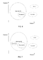
- FIGS. 7 and 8 illustrate various classification methods encompassed by the present invention which include a contra-ictal class in 2D feature space.
- FIG. 9 illustrates a plotting of two-dimensional feature vectors in a two-dimensional feature space with different combination of variables (features).
- FIG. 10 illustrates a plotting of two-dimensional feature vectors in a two dimensional feature space with contours indicating minimum time to seizure.
- FIG. 11 is an overlay of an output from a contra-ictal classifier over an output of a pro-ictal classifier.
- FIG. 12 is a sample truth chart that may be used to determine a communication output provided to the subject.
- FIG. 13 illustrates a simplified system embodied by the present invention which comprises one or more implantable devices in communication with an external device.
- FIG. 14 illustrates simplified methods of operating the system of the present invention.
- FIG. 15A illustrates a bottom view of one embodiment of an active implantable device that is encompassed by the present invention.
- FIG. 15B illustrates a cross-sectional view of the active implantable device of FIG. 15A along lines B-B.
- FIG. 15C is a linear implantable device that comprises a plurality of electrode contacts in which at least one electrode contact comprises the active implantable device of FIG. 15A .
- FIG. 15D is a cross sectional view of the implantable device of FIG. 15C along lines D-D.
- FIG. 15E is a 4 ⁇ 4 electrode array that comprises a plurality of electrode contacts in which at least one electrode contact comprises the active implantable contact of FIG. 15A .
- FIG. 16A is a cross-sectional view of another embodiment of an implantable device that is encompassed by the present invention.
- FIG. 16B is a cross-sectional view of another embodiment of the implantable device in which a conductive can forms a housing around the electronic components and acts as an electrode.
- FIG. 16C illustrates a simplified plan view of an embodiment that comprises four electrodes disposed on the implanted device.
- FIG. 17 illustrates one embodiment of the electronic components that may be disposed within the implantable device.
- FIG. 18 is a block diagram illustrating one embodiment of electronic components that may be in the external device.
- FIG. 19 illustrates a simplified trocar or needle-like device that may be used to implant the implantable device beneath the subject's skin.
- FIG. 20 illustrates a simplified trocar or needle-like device that may be used to implant the implantable device within a burr hole in the subject's skull.
- FIG. 21 illustrates a method of inserting an implantable device in the subject and wirelessly sampling EEG signals from a subject.
- FIG. 22 illustrates a method of using an implantable device in the subject to determine if the subject is in a contra-ictal condition.
- FIG. 23 is a kit in accordance with embodiments of the present invention.
- the invention is not limited to measuring EEG signals or to determining when the subject is in a contra-ictal state.
- the invention could also be used in systems that measure one or more of a blood pressure, blood oxygenation (e.g., via pulse oximetry), temperature of the brain or of portions of the subject, blood flow measurements, ECG/EKG, heart rate signals, respiratory signals, chemical concentrations of neurotransmitters, chemical concentrations of medications, pH in the blood, or other physiological or biochemical parameters of a subject.
- the present invention may also be applicable to monitoring other neurological or psychiatric disorders and identifying a condition or state for such disorders in which the subject is unlikely to experience some adverse effect.
- the present invention may also be applicable to monitoring and management of sleep apnea, Parkinson's disease, essential tremor, Alzheimer's disease, migraine headaches, depression, eating disorders, cardiac arrhythmias, bipolar spectrum disorders, or the like.
- the features extracted from the signals and used by the algorithms will be specific to the underlying disorder that is being managed. While certain features may be relevant to epilepsy, such features may or may not be relevant to the state measurement for other disorders.
- One embodiment of the present invention identifies and uses a contra-ictal classification for each subject in which the subject is highly unlikely to transition to the ictal state within a specified time period.
- the contra-ictal condition can be considered to be a subset of the inter-ictal class or it can be considered to be a completely new neurological classification. While it is beneficial to the subject to know if the subject is in the inter-ictal condition, being in the inter-ictal condition does not necessarily inform the subject that they will not quickly transition from the inter-ictal condition to the ictal condition.
- Being able to inform a subject that they are in a contra-ictal state can allow the subject to engage in normal daily activities, such as walking down a set up stairs, without fearing that they will have a seizure or without fearing that they may quickly transition into a pro-ictal state. Knowing when a seizure is unlikely to occur can be even more important to the subject's freedom than being alerted when a seizure is likely to occur.
- the period of time associated with the contra-ictal state will vary depending on the implementation of the algorithm.
- the period of time could be a predetermined time period as determined from the training data and programmed into the algorithm, such as 10 minutes, 20 minutes, 30 minutes, 60 minutes, 90 minutes or more.
- the algorithm could compute the period, which may be different from episode to episode for a single subject. Thus, for some subjects, the period of time could span many hours or even days or weeks.
- Proposed seizure prediction systems only attempt to differentiate between a pre-ictal state and an inter-ictal state for purposes of seizure prediction.
- embodiments of the present invention may further identify the contra-ictal condition or state for the particular subject.
- FIG. 1A illustrates a simplified method of identifying a contra-ictal state for the subject.
- the method of FIG. 1A is typically performed in a computer system in a physician's office, but it could also be performed in a central processing computer workstation remote from the physician, or even in a subject's external data device or implanted communication unit (shown in FIG. 9 ).
- a training dataset of the subject is obtained and annotated to identify the ictal activity.
- the training data could span days or weeks, and is preferably a substantially continuous monitoring of the subject's EEG signals using an array of scalp or intracranial electrodes.
- the training data comprises a plurality of ictal events separated by inter-ictal intervals.
- the training set of physiological signals typically includes a training set of intracranial EEG recordings from the subject's long term visit to an epilepsy monitoring unit (EMU).
- EMU epilepsy monitoring unit
- the EEG training sets could be obtained from the ambulatory system utilizing an implantable device and external device as described below.
- EEG signals are currently the desirable physiological signals that are analyzed, any of the aforementioned physiological signals could be used to train the algorithms.
- the training set may be overlaid with comments from a physician and/or a marking algorithm may automatically identify some or all of the ictal activity in the training set—such as epileptiform spikes, earliest electrographic change (EEC), unequivocal electrical onset of seizure (UEO), unequivocal clinical onset (UCO), end of electrographic seizure (EES), etc.
- EEC epileptiform spikes
- UEO unequivocal electrical onset of seizure
- UO unequivocal clinical onset
- EES end of electrographic seizure
- N feature extractors may be applied to the training set to quantify relevant aspects of the EEG training dataset. Any number of features can be extracted from the EEG signals in order to assess the subject's condition.
- an N-dimensional feature vector will be formed for each of the N features that are extracted.
- the extracted N-dimensional feature vectors may then be allocated or plotted in an N-dimensional feature space. While not shown in FIG. 1A , the invention may also be used with lower dimension spaces created through application of data transformations to the N-dimensional feature vector, including but not limited to, principle components analysis, factor analysis, or linear discriminant analysis.
- one aspect of the present invention utilizes an unsupervised learning protocol to identify a contra-ictal condition for the subject by utilizing an algorithm or other means to identify a region of the feature space or clusters or groupings of feature vectors in the N-dimensional feature space that are substantially devoid of feature vectors that are in an ictal condition and for which all feature vectors in the grouping or region are separated from an ictal event (e.g., seizure) by a predetermined time period (step 10 ).
- the N-dimensional feature space may be partitioned into a collection of N-dimensional hypercubes.
- a hypercube that is substantially devoid of training vectors that occur within a predetermined time period prior to the next seizure may be labeled contra-ictal.
- a binary space partitioning algorithm can be used to partition the N-dimensional feature space into a collection of N-dimensional hyperprisms.
- a hyperprism that is substantially devoid of training vectors that occur within a predetermined time period prior to the next seizure may be labeled contra-ictal.
- the structure of the training data may be approximated by an expansion of radial basis function, e.g. a Gaussian mixture model. Each feature vector in the training data may be assigned to one component of the radial basis function expansion using, e.g., Bayesian posterior probability or decision risk criteria.
- a component that is substantially devoid of training vectors that occur within a predetermined time period prior to the next seizure may be labeled contra-ictal.
- the algorithm may also identify other classes of interest from the EEG training dataset (e.g., inter-ictal that is not part of the contra-ictal class, pro-ictal, ictal, post-ictal, or the like), and the classes of interest (or groupings of feature vectors) for the subject and/or mathematical representations thereof are stored in memory for later use in the subject system implanted or otherwise used by the subject.
- each identified partition in the N-dimensional feature space can be assigned an identifier that may be used to represent states in a Markov chain, or symbols emitted by hidden states in a hidden Markov model. These identifiers, or sequences of identifiers may be used to make inferences about future states, and thereby the likelihood of seizure occurrence.
- Similar approaches may be used to derive and train a pro-ictal algorithm.
- an algorithm or other means may be used to identify a region of the feature space or clusters or groupings of feature vectors in the N-dimensional feature space that frequently precede an ictal state by a predetermined period of time but occur infrequently in inter-ictal intervals.
- a prior art seizure prediction algorithm may be used.
- FIG. 1B shows another embodiment of a method of identifying a contra-ictal state for a subject. This method tracks the method of FIG. 1A for steps 2 , 4 , 6 and 8 .
- FIG. 1B adds a step 9 , however, that involves identifying a grouping of points or a region in the N-dimensional feature space that occurs within a predetermined time of seizure activity.
- step 10 of this method the method then identifies a grouping of points or a region in the N-dimensional feature space that is substantially free from pro-ictal activity feature vectors and is separated in time from the pro-ictal activity by a predetermined time period using, e.g., the techniques discussed above with respect to step 10 of FIG. 1A .
- FIG. 1C shows yet another embodiment of a method of identifying a contra-ictal state for a subject. Once again, this method tracks the method of FIG. 1A for steps 2 , 4 , 6 and 8 . Like the method of FIG. 1B , FIG. 1C adds a step 9 that involves identifying a grouping of points or a region in the N-dimensional feature space that occurs within a predetermined time of seizure activity.
- step 10 of this method the method then identifies a grouping of points or a region in the N-dimensional feature space that is substantially free from both pro-ictal activity feature vectors and seizure feature vectors, and is separated in time from the seizure and pro-ictal activity by a predetermined time period using, e.g., the techniques discussed above with respect to step 10 of FIG. 1A .
- FIG. 2 depicts an example of the overall structure of a system for performing substantially real-time assessment of the subject's brain activity and for determining the communication output that is provided to the subject.
- the system may comprise one or more algorithms or modules that process input data 12 .
- the algorithms may take a variety of different forms, but typically comprises one or more feature extractors 14 a , 14 b , 15 and at least one classifier 16 , 17 .
- the algorithms used in the system may use exactly the same feature extractors or completely different feature extractors (not shown).
- the input data 12 is typically EEG, but may comprise representations of physiological signals obtained from monitoring a subject and may comprise any one or combination of the aforementioned physiological signals from the subject.
- the input data may be in the form of analog signal data or digital signal data that has been converted by way of an analog to digital converter (not shown).
- the signals may also be amplified, preprocessed, and/or conditioned to filter out spurious signals or noise.
- the input data of all of the preceding forms is referred to herein as input data 12 .
- the input data comprises between about 1 channel and about 64 channels of EEG from the subject.
- the input data 12 from the selected physiological signals is supplied to the one or more feature extractors 14 a , 14 b , 15 .
- Feature extractor 14 a , 14 b , 15 may be, for example, a set of computer executable instructions stored on a computer readable medium, or a corresponding instantiated object or process that executes on a computing device. Certain feature extractors may also be implemented as programmable logic or in a fixed logic device. In general, feature extractors 14 a , 14 b , 15 can process data 12 and identify some characteristic of interest in the data 12 .
- Feature extractors used in the subject system are typically the same feature extractors used in the method described in the method of FIG. 1 . Such a characteristic of the data is referred to herein as an extracted feature.
- Each feature extractor 14 a , 14 b , 15 may be univariate (operating on a single input data channel), bivariate (operating on two data channels), or multivariate (operating on multiple data channels).
- Some examples of potentially useful characteristics to extract from signals for use in determining the subject's propensity for a neurological event include but are not limited to bandwidth limited power (alpha band [8-13 Hz], beta band [13-18 Hz], delta band [0.1-4 Hz], theta band [4-8 Hz], low beta band [12-15 Hz], mid-beta band [15-18 Hz], high beta band [18-30 Hz], gamma band [30-48 Hz], high frequency power [>48 Hz], bands with octave or half-octave spacings, wavelets, etc.), second, third and fourth (and higher) statistical moments of the EEG amplitudes or other features, spectral edge frequency, decorrelation time, Hjorth mobility (HM), Hjorth complexity (HC), the
- each classifier 16 , 17 may be, for example, a set of computer executable instructions stored on a computer readable medium or a corresponding instantiated object or process that executes on a computing device. Certain classifiers may also be implemented as programmable logic or in a fixed logic device.
- the classifiers 16 , 17 analyze one or more of the extracted characteristics, and either alone or in combination with each other (and possibly other subject dependent parameters), provide a result 18 that may characterize, for example, a subject's condition.
- the output from the classifiers may then be used to determine the output communication that is provided to the subject regarding their condition.
- the classifiers 16 , 17 are trained by exposing them to training measurement vectors, typically using supervised methods for known classes, e.g. ictal, and unsupervised methods as described above for classes that can't be identified a priori, e.g. contra-ictal.
- classifiers include k-nearest neighbor (“KNN”), binary and higher order space partitions, linear or non-linear regression, Bayesian, mixture models based on Gaussians or other basis functions, neural networks, and support vector machines (“SVM”).
- KNN k-nearest neighbor
- SVM support vector machines
- Each classifier 16 , 17 may provide a variety of output results, such as a logical result or a weighted result.
- the classifiers 16 , 17 may be customized for the individual subject and may be adapted to use only a subset of the characteristics that are most useful for the specific subject. Additionally, over time, the classifiers 16 , 17 may be further adapted to the subject, based, for example, in part on the result of previous analyses and may reselect extracted characteristics that are used for the specific subject.
- the pro-ictal classifier 17 may classify the outputs from feature extractors 14 a , 14 b to detect characteristics that indicate that the subject is at an elevated susceptibility for a neurological event, while the contra-ictal classifier 16 may classify the outputs from feature extractors 14 a , 14 b , 15 to detect characteristics that occur when the subject is unlikely to transition into an ictal condition for a specified period of time.
- the combined output of the classifiers 16 , 17 may be used to determine the output communication provided to the subject.
- the output from the contra-ictal classifier 16 alone may be used to determine the output communication to the subject.
- FIG. 3 illustrates a Venn diagram illustrating a simplified approximation of the relationship of the neurological states or conditions of subjects diagnosed with epilepsy.
- the ictal state 26 is the actual period in which the subject is experiencing a seizure. As previously mentioned, the “average” subject is in the ictal state approximately 0.02% of the overall time. Therefore, the associated sizes of the Venn diagram set areas are not meant to be representative of the overall time the subject is in the various states, otherwise, the ictal period would be approximately 5,000 times smaller than the inter-ictal period.
- the inter-ictal state 22 is sometimes termed the “normal” neurological state and represents the neurological state between seizures.
- the post-ictal state 28 is the neurological state immediately following a seizure or ictal 26 state.
- the transitions are also depicted in this three state model.
- the neurological state transitions 202 from the inter-ictal state to the ictal state.
- the neurological state transitions 200 to the post-ictal state and then transitions 204 to the inter-ictal state.
- seizure clustering it is also possible for the subject to transition 200 from the post-ictal state to the ictal state.
- FIG. 4 illustrates an additional state, pre-ictal 27 , which occurs between the inter-ictal state and the seizure or ictal state.
- EEGs electroencephalogram or electrocorticograms
- pre-ictal condition i.e., pre-seizure condition
- inter-ictal condition i.e., between seizures
- FIG. 5 illustrates two additional neurological states. These states, contra-ictal and pro-ictal, are shown as subsets within the inter-ictal state.
- the contra-ictal state 29 is referred to as a “low susceptibility to seizure” condition for a time period.
- the pro-ictal state 24 represents a neurological state having a high susceptibility for a seizure. As shown it is possible for the neurological contra-ictal state to transition back into the general inter-ictal state (transition 218 ) or into a pro-ictal state (transition 216 ). As shown by transitions 216 , 222 and 202 , it is possible for the neurological pro-ictal state to transition to the contra-ictal state, the inter-ictal state or the ictal state. The subject may also go from an inter-ictal state to an ictal state.
- FIGS. 6 to 12 illustrate different aspects of the systems encompassed by the present invention.
- the classifiers may have multiple classes (e.g., two or more), may provide a weighted answer, or they may provide an output that is expressed as a continuum between the contra-ictal and pro-ictal conditions, with a scalar or vector of parameters describing the actual condition and its variations.
- a multiple class classifier may have labels such as ‘inter-ictal’ 22 , ‘pro-ictal’ 24 , ‘ictal’ 26 , or ‘post-ictal’ 28 .
- the classifiers 16 , 17 are one-class classifiers that calculate probability of class membership (probability of pro-ictal, probability of contra-ictal).
- FIGS. 7 and 8 as they relate to the seizure advisory system, one implementation of a classification of conditions defined by the classifiers 16 , 17 includes (1) an inter-ictal class 22 (sometimes referred to as a “normal” condition), (2) a pro-ictal class 24 (sometimes referred to as an “abnormal” or “high-susceptibility to seizure” condition), (3) an ictal class 26 (sometimes referred to as a “seizure” condition), (4) a post-ictal class 28 (sometimes referred to as a “post-seizure” condition), and (5) a contra-ictal condition 29 (sometimes referred to as a “low susceptibility to seizure for a time period” condition).
- FIG. 7 illustrates the contra-ictal class 29 as a sub-set of the inter-ictal class 28 while FIG. 8 illustrates the contra-ictal class 29 as a separate class from the inter-ictal class 28 .
- FIG. 9 illustrates an example of 2-dimensional projections of an N-dimensional feature space extracted from subject physiological data, such as EEG data.
- the dark data points are feature vectors that occur within 20 minutes of a subsequent seizure. These data points are therefore labeled pro-ictal.
- the lighter points are inter-ictal feature vectors that occur more than 3 hours prior to a seizure.
- the projection onto variables 15 and 21 and variables 36 and 44 in the left column of FIG. 9 there does not appear to be any differentiable clusters or groupings between the two groups.
- variable 2 and 18 and variable 1 and 34 in the right column of FIG. 9 there is a more defined separation between the two classes.
- the pro-ictal class is included in the inter-ictal class, there are areas outlined by the dotted lines 30 in both two-dimensional projections that are substantially free of pro-ictal feature vectors.
- FIG. 10 illustrates one of the 2-dimensional projections of an N-dimensional features space of FIG. 9 for variable 2 versus 18 .
- contour lines regarding the time elapsed prior to a seizure. For the area marked by “A” all the feature vectors occur more than 5 minutes prior to a seizure. For the area marked by “B” all the feature vectors occur more than 15 minutes prior to the seizure. For areas marked by “C”, “D”, “E” all of the feature vectors occur more than 30, 60 and 90 minutes prior to the seizure, respectively.
- this 2-dimensional projection one may also adjust/customize the green light for indicating the “contra-ictal” state by selecting the time to seizure contour line (e.g. 15, 30, 60, 90, etc.).
- FIGS. 11 and 12 illustrate how the outputs from two one-state classifiers within a trained analysis algorithm in a patient monitoring device may be used to determine the output communication provided to the subject.
- FIG. 11 illustrates an example of the output from the contra-ictal classifier 40 overlaid on an output from the pro-ictal classifier 42 .
- FIG. 12 is a truth table 50 that processes the outputs from the classifiers to determine the output communication provided to the subject.
- the truth table 50 of FIG. 12 shows the different possible combinations of outputs from the each of the classifiers and the associated output communication provided to the subject.
- the potential output to the subject includes a green light, a yellow light and a red light.
- a green light may indicate to the subject that they are at a low susceptibility to a seizure for a time period.
- a yellow light (or some other indication) may indicate to the subject to proceed with caution. Such an indication does not necessarily mean that the subject is at a high susceptibility to have a seizure, but it does mean that it is possible to have a seizure within a predetermined time (such as 90 minutes, etc.).
- a red light (or some other indication) may indicate to the subject that they are at an elevated susceptibility for a seizure.
- FIGS. 11 and 12 describe providing an output to the subject in the form of yellow lights, green lights and red lights
- the present invention embodies any number of different type of outputs may be provided to the subject to indicate their condition.
- the subject's condition could, alternatively, be indicated by the absence of an output.
- the system could comprise a yellow light and a red light, and the lack of either the red light or yellow light being illuminated would indicate the subject is in a contra-ictal state.
- the outputs may be different displays on a screen to the subject, different tactile outputs (e.g., vibrations), different sounds, different lights, or any combination thereof. Additionally, such outputs are not limited to the patient/subject, rather the output may be provided to a caregiver.
- Caregivers may include a physician, nurse or relative, or the like. Furthermore, such output may also provide the inputs to either a closed loop or open loop therapeutic response which attempts to minimize and/or prevent a seizure occurrence.
- Such therapeutic approaches may include, without limitation, vagus nerve stimulation, deep brain stimulation, neurostimulation, automated/semi-automated or manual dispensing of antiepileptic drugs, and biofeedback techniques.
- both classifier outputs 40 , 42 are considered to be below an artificially specified threshold 44 and are both considered to be “low.”
- anything below the threshold 44 indicates that there is a low likelihood that the subject is in a pro-ictal state and/or a low likelihood that the subject is in a contra-ictal state.
- the output communication provided to the subject may indicate that that the subject should proceed with caution.
- One example of such an output communication is a yellow light. This output corresponds to the first row 52 of the truth table 50 of FIG. 12 .
- the output 40 from the contra-ictal classifier is high (H) and the output from the pro-ictal classifier 42 is low (L).
- H high
- L low
- Such a classification indicates that there is a low likelihood that the subject has an increased susceptibility for a seizure and a high likelihood of being in a contra-ictal state.
- These classifiers appear to be consistent with each other; consequently, the output communication provided to the subject may indicate that the subject is in a contra-ictal state.
- One example of such an output communication is the display of a green light. This scenario corresponds to the second row 54 of FIG. 12 .
- the output 40 from the contra-ictal classifier has fully transitioned to low (L) (e.g., low likelihood that the subject is in a contra-ictal state) and the output 42 from the pro-ictal classifier is above threshold 44 and is high (H) (e.g., high likelihood that the subject is at an increased susceptibility to a seizure).
- L low likelihood that the subject is in a contra-ictal state
- H high likelihood that the subject is at an increased susceptibility to a seizure
- different thresholds are used for the contra-ictal and pro-ictal classifiers.
- the contra-ictal classifier output 40 could be compared to a higher threshold 43
- the pro-ictal classifier output 42 could be compared to the lower threshold 44 .
- the contra-ictal indication (e.g., green light) might be provided if the contra-ictal classifier output 40 exceeds the threshold 43 and if the pro-ictal classifier output 42 does not exceed the threshold 44 ;
- the pro-ictal indication (e.g., red light) might be provided if the contra-ictal classifier output 40 does not exceed threshold 43 and if the pro-ictal classifier output 42 exceeds threshold 44 ;
- an indication that the outputs are inconclusive e.g., a yellow light
- FIGS. 11 and 12 illustrate the use of two one-class classifiers
- any number and type of classifier may be used by the systems of the present invention.
- the output of the classification algorithm would indicate the existence of a contra-ictal condition (e.g., a green light) so long as the extracted feature vector corresponds only with training points that almost never preceded a seizure by less than the predetermined time period, such as 90 minutes.
- the output of the classification algorithm would indicate the existence of a pro-ictal condition (e.g., a red light) if the extracted feature corresponds to a region of the feature space indicative of pro-ictal state. This indication is not a seizure prediction; a pro-ictal condition might resolve without a seizure ever occurring. The end of a contra-ictal indication does indicate, however, that it is no longer unlikely that a seizure will occur within 90 minutes (or other predetermined time).
- the pro-ictal indication does not.
- the subject may stay in a pro-ictal state for a prolonged period of time, or the subject might leave the pro-ictal state immediately after entering it.
- the classification algorithm for a contra-ictal indication can be derived by determining the kinds of feature vectors that never preceded a pro-ictal condition by less than a predetermined time.
- this contra-ictal classification algorithm would indicate a contra-ictal condition (such as be lighting a green light) when a feature vector extracted from a subject's physiological signal (such as an EEG) corresponds to one of such feature vectors, thereby indicating that the subject is unlikely to transition to a pro-ictal state within that predetermined time period.
- the contra-ictal indication classification algorithm can be derived by determining the kinds of feature vectors that never preceded a pro-ictal condition by less than a predetermined time and never preceded a seizure by less than the predetermined time.
- this contra-ictal classification algorithm would indicate a contra-ictal condition (such as be lighting a green light) when a feature vector extracted from a subject's physiological signal (such as an EEG) corresponds to one of such feature vectors, thereby indicating that the subject is unlikely to transition to either a pro-ictal state or to a seizure within that predetermined time period.
- FIG. 13 illustrates one example of a system in which the algorithms 19 , 20 ( FIG. 2 ) of the present invention may be embodied.
- System 60 includes one or more implantable devices 62 that are configured to sample electrical activity from the subject's brain (e.g., EEG signals). Suitable systems including minimally-invasive implantable devices are described in commonly-owned U.S. patent application Ser. No. 11/766,742, filed Jun. 21, 2007, to Harris et al., the complete disclosure of which is incorporated herein by reference.
- the implantable devices 62 may be active (with internal power source), passive (no internal power source), or semi-passive (internal power source to power components, but not to transmit data signal).
- the implantable devices 62 may be implanted anywhere in the subject, but typically one or more of the devices 62 may be implanted adjacent a previously identified epileptic focus or a portion of the brain where the focus is believed to be located. It may also be desirable to position one or more of the implantable devices distal to the epileptic focus.
- the system 60 is used to monitor a neurological condition of subject 62 for purposes of estimating a subject's susceptibility for a neurological event.
- the system 60 of the illustrated embodiment provides for substantially continuous sampling and analysis of brain wave electrical signals.
- the devices 62 themselves may be used to help determine the location of the epileptic focus.
- the physician may implant any desired number of devices in the subject. In some embodiments between about 1 and about 32 channels are provided, and preferably between about 8 and about 16 channels are provided. As noted above, in addition to monitoring brain signals, one or more additional implanted devices 62 may be implanted to measure other physiological signals from the subject.
- Implantable devices 62 While it may be possible to implant the implantable devices 62 under the skull and in or on the brain, it is preferred to implant the implantable devices 62 in a minimally invasive fashion under at least one layer of the subject's scalp and above the skull. Implantable devices 62 may be implanted between any of the layers of the scalp (sometimes referred to herein as “sub-galeal”).
- the implantable devices may be positioned between the skin and the connective tissue, between the connective tissue and the epicranial aponeurosis/galea aponeurotica, between the epicranial aponeurosis/galea aponeurotica and the loose areolar tissue, between the loose areolar tissue and the pericranium, and/or between the pericranium and the calvarium.
- Implantable devices 62 will typically be configured to substantially continuously sample the brain activity of the groups of neurons in the immediate vicinity of the implanted device.
- the electrodes may be sized to be able to sample activity of a single neuron in the immediate vicinity of the electrode (e.g., a microelectrode).
- the implantable device 62 will be interrogated and powered by a signal from the external device to facilitate the substantially continuous sampling of the brain activity signals.
- Sampling of the brain activity is typically carried out at a rate above about 200 Hz, and preferably between about 200 Hz and about 1000 Hz, and most preferably at about 400 Hz, but it could be higher or lower, depending on the specific condition being monitored, the subject, and other factors.
- Each sample of the subject's brain activity will typically contain between about 8 bits per sample and about 32 bits per sample, and preferably between about 12 bits per sample and about 16 bits per sample.
- the data transfer rate from the implantable devices 62 to the external device 64 is at least about 6.4 Kbits/second.
- the total data transfer rate for the system 60 would be about 205 Kbits/second.
- the implantable devices 62 may be configured to sample the brain activity signals periodically (e.g., once every 10 seconds) or aperiodically.
- Implantable device 62 may comprise a separate memory module for storing the recorded brain activity signals, a unique identification code for the device, algorithms, other programming, or the like.
- a subject instrumented with the implanted devices 62 will typically carry a data collection device 64 that is external to the subject's body.
- the external device 64 would receive and store the signal from the implanted device 62 with the encoded EEG data (or other physiological signals).
- the external device is typically of a size so as to be portable and carried by the subject in a pocket or bag that is maintained in close proximity to the subject.
- the device may be configured to be used in a hospital setting and placed alongside a subject's bed.
- Communication between the data collection device 64 and the implantable device 62 typically takes place through wireless communication.
- the wireless communication link between implantable device 62 and external device 64 may provide a communication link for transmitting data and/or power.
- External device 64 may include a control module 66 that communicates with the implanted device through an antenna 68 .
- antenna 68 is in the form of a necklace that is in communication range with the implantable devices 62 .
- control module 66 may be attached around an arm or belt of the subject, integrated into a hat, integrated into a chair or pillow, and/or the antenna may be integrated into control module 66 .
- the antenna of the external device and the implantable devices must be in communication range of each other.
- the frequency used for the wireless communication link has a direct bearing on the communication range.
- the communication range is between at least one foot, preferably between about one foot and about twenty feet, and more preferably between about six feet and sixteen feet.
- the present invention is not limited to such communication ranges, and larger or smaller communication ranges may be used. For example, if an inductive communication link is used, the communication range will be smaller than the aforementioned range.
- the interface may take the form of a magnetically attached transducer, as with cochlear implants. This could enable power to be continuously delivered to the implanted devices 62 and provide for higher rates of data transmission.
- system 60 may include one or more intermediate transponders (not shown) that facilitates data transmission and power transmission between implantable device 62 and external device 64 .
- the intermediate transponder may be implanted in the subject or it may be external to the subject. If implanted, the intermediate transponder will typically be implanted between the implantable device 62 and the expected position of the external device 64 (e.g., in the neck, chest, or head). If external, the transponder may be attached to the subject's skin, positioned on the subject's clothing or other body-worn assembly (e.g., eyeglasses, cellular phone, belt, hat, etc.) or in a device that is positioned adjacent the subject (e.g., a pillow, chair headrest, etc.).
- body-worn assembly e.g., eyeglasses, cellular phone, belt, hat, etc.
- the intermediate transponder may be configured to only transmit power, only transmit data, or it may be configured to transmit both data and power.
- the external device 64 may be placed outside of its normal communication range from the implanted devices 62 (e.g., on a subject's belt or in a subject's bag), and still be able to substantially continuously receive data from the implantable device 62 and/or transmit power to the implantable device 62 .
- Radiofrequency link Transmission of data and power between implantable device 62 and external device 64 is typically carried out through a radiofrequency link, but may also be carried out through magnetic induction, electromagnetic link, Bluetooth(R) link, Zigbee link, sonic link, optical link, other types of wireless links, or combinations thereof.
- One preferred method 61 of wirelessly transmitting data and power is carried out with a radiofrequency link, similar to the link used with radiofrequency identification (RFID) tags.
- RFID radiofrequency identification
- one or more radio frequency signals are emitted from the external device 64 through antenna 68 (step 143 ). If the external device 64 is in communication range of the implantable devices, at step 145 the radiofrequency (RF) energy signal illuminates the passive, implantable devices 62 .
- the same RF signal interrogates the energized implantable device 62 to allow the implantable device to sample the desired physiological signal from the subject (such as an EEG signal).
- the implantable device samples the instantaneous EEG signal (or other physiological signal) from the subject.
- the implantable device 62 then communicates a return RF signal to the external device 64 that is encoded with data that is indicative of the sampled EEG signal.
- the return RF signal is a based on the RF signal generated by the external device and includes detectable modifications which indicate the sampled EEG signal.
- the return signal is typically a backscattering of the RF signal from the external device with the detectable modifications that indicate the sampled EEG signal.
- backscattering does not require generation of a separate radiating signal and would not require an internal power source.
- the return RF signals may also include the identification code of the implanted device so as to identify which device the data is coming from.
- the return RF signal emitted by the internal device 62 is received by the antenna 68 , and the RF signal is decoded to extract the sampled EEG signal.
- the sampled EEG signal may thereafter be stored in a memory of the external device 64 .
- data will be stored until accessed by the subject.
- data will be analyzed on a separate device (e.g., physician's computer workstation).
- the received RF signal with the sampled EEG may be analyzed by the EEG analysis algorithms to estimate the subject's brain state which is typically indicative of the subject's propensity for a neurological event (step 155 ).
- the neurological event may be a seizure, migraine headache, episode of depression, tremor, or the like.
- the estimation of the subject's brain state may cause generation of an output (step 157 ).
- the output may be in the form of a control signal to activate a therapeutic device (e.g., implanted in the subject, such as a vagus nerve stimulator, deep brain or cortical stimulator, implanted drug pump, etc.).
- the output may be used to activate a user interface on the external device to produce an output communication to the subject.
- the external device may be used to provide a substantially continuous output or periodic output communication to the subject that indicates their brain state and/or propensity for the neurological event.
- Such a communication could allow the subject to manually initiate therapy (e.g., wave wand over implanted vagus nerve stimulator, cortical, or deep brain stimulator, take a fast acting AED, etc.) or to make themselves safe.
- the return RF signal is transmitted (e.g., backscattered) immediately after sampling of the EEG signal to allow for substantially real-time transfer (and analysis) of the subject's EEG signals.
- the return RF signal may be buffered in an internal memory and the communication transmission to the external device 64 may be delayed by any desired time period and may include the buffered EEG signal and/or a real-time sampled EEG signal.
- the return RF signal may use the same frequency as the illumination RF signal or it may be a different frequency as the illumination RF signal.
- some embodiments of the methods and devices of the present invention substantially continuously sample physiological signals from the subject and communicate in real-time small amounts of data during each return RF signal communication. Because only small amounts of data (one or a small number of sampled EEG signals from each implantable device 62 ) are transmitted during each communication, a lower amount of power is consumed and the illumination of the implanted device from the incoming high-frequency RF signal will be sufficient to power the implantable device 62 for a time that is sufficient to allow for sampling of the subject's EEG signal. Consequently, in most embodiments no internal power source, such as a battery, is needed in the implantable device 62 —which further reduces the package size of the implantable device 62 .
- the implantable devices 62 and the external devices 64 of the present invention typically use an electromagnetic field/high frequency communication link to both illuminate the implantable device and enable high data transfer rates.
- Conventional systems typically have an internally powered implantable device and use a slower communication link (e.g., that is designed for long link access delays) and transmit data out on a non-continuous basis.
- some embodiments of the present invention use a fast access communication link that transmits a smaller bursts of data (e.g., single or small number of EEG sample at a time) on a substantially continuous basis.
- the frequencies used to illuminate and transfer data between the implantable devices 62 and external device 64 are typically between 13.56 MHz and 10 GHz, preferably between 402 MHz and 2.4 GHz, more preferably between 900 MHz and 2.4 GHz. While it is possible to use frequencies above 2.4 GHz, Applicants have found that it is preferred to use a frequency below 2.4 GHz in order to limit attenuation effects caused by tissue. As can be appreciated, while the aforementioned frequencies are the preferred frequencies, the present invention is not limited to such frequencies and other frequencies that are higher and lower may also be used. For example, it may be desirable us use the MICS (Medical Implant Communication Service band) that is between 402-405 MHz to facilitate the communication link. In Europe, it may be desirable to use ETSI RFID allocation 869.4-869.65 MHz.
- MICS Medical Implant Communication Service band
- the system 60 of the present invention may also make use of conventional or proprietary forward error correction (“FEC”) methods to control errors and ensure the integrity of the data transmitted from the implantable device 62 to the external device 64 .
- FEC forward error correction
- Such forward error correction methods may include such conventional implementations such as cyclic redundancy check (“CRC”), checksums, or the like.
- the data signals that are wirelessly transmitted from implantable device 62 may be encrypted prior to transmission to the control module 66 .
- the data signals may be transmitted to the control module 66 as unencrypted data, and at some point prior to the storage of the data signals in the control module 66 or prior to transfer of the data signals to the physician's office, the EEG data may be encrypted so as to help ensure the privacy of the subject data.
- FIGS. 16A and 16B illustrate two embodiments of the externally powered leadless, implantable device 62 that may be used with the system 60 of the present invention.
- the implantable devices 62 of the present invention are preferably passive or semi-passive and are “slaves” to the “master” external device 64 .
- the implantable devices will typically remain dormant until they are interrogated and possibly energized by an appropriate RF signal from the external device 64 .
- the implantable device 64 may have minimal electronic components and computing power, so as to enable a small package size for the implantable device.
- the embodiment illustrated in FIGS. 16A and 16B are minimally invasive and may be implanted with an introducer, trocar or syringe-like device under local anesthesia by a physician or potentially even a physician's assistant.
- the implanted device of FIG. 16A may have a longitudinal dimension 1620 of less than about 3 cm, and preferably between about 1 cm and about 10 cm, and a lateral dimension 1622 of less than about 2 mm, and preferably between about 0.5 mm and about 10 mm.
- such dimensions are merely illustrative, and other embodiments of implanted device may have larger or smaller dimensions.
- FIG. 16A illustrates an embodiment that comprises a first electrode 1624 and a second electrode 1626 that are disposed on opposing ends of housing 1628 .
- the first and second electrodes 1624 , 1626 may be composed of platinum, platinum-iridium alloy, stainless steel, or any other conventional material.
- the electrodes may include a coating or surface treatment such as platinum-iridium or platinum-black in order to reduce electrical impedance.
- the first and second electrodes 1624 , 1626 will typically have a smooth or rounded shape in order to reduce tissue erosion and may have a surface area of about 3 mm 2 , but other embodiments may be smaller or larger.
- electrodes 1624 , 1626 are typically adapted to only sense physiological signals and are not used to deliver stimulation, the surface area of the electrodes may be smaller than conventional implantable devices.
- the smaller electrodes have the advantage of reducing the overall device size which can be beneficial for improving subject comfort and reducing the risk of tissue erosion.
- Housing 1628 is typically in the form of a radially symmetrical, substantially cylindrical body that hermetically seals electronic components 1630 disposed within a cavity 1632 .
- Housing 1628 may be composed of a biocompatible material, such as glass, ceramic, liquid crystal polymer, or other materials that are inert and biocompatible to the human body and able to hermetically seal electronic components.
- Housing 1628 may have embedded within or disposed thereon one or more x-ray visible markers 33 that allow for x-ray localization of the implantable device. Alternatively, one or more x-ray visible markers may be disposed within the cavity 1632 .
- Cavity 1632 may be filled with an inert gas or liquid, such as an inert helium nitrogen mixture which may also be used to facilitate package leakage testing.
- the liquid encapsulant may comprise silicone, urethane, or other similar materials.
- housing 1628 is illustrated as a substantially cylindrical body with the electrodes 1624 , 1626 on opposing ends, housing may take any desired shape and the electrodes may be positioned at any position/orientation on the housing 1628 .
- housing 1628 may taper in one direction, be substantially spherical, substantially oval, substantially flat, or the like. Additionally or alternatively, the body may have one or more substantially planar surfaces so as to enhance the conformity to the subject's skull and to prevent rotation of the implantable device 62 .
- housing 1628 may optionally include a conductive electromagnetic interference shield (EMI) that is configured to shield the electronic components 1630 in housing 1628 .
- the EMI shield may be disposed on an inner surface of the housing, outer surface of the housing, or impregnated within the housing.
- housing 1628 may optionally comprise an anchoring assembly (not shown) that improves the anchoring of the implantable device 62 to the skull or the layers within the scalp.
- anchoring may be carried out with adhesive, spikes, barbs, protuberances, suture holes, sutures, screws or the like.
- first electrode 1624 is disposed on a first end of housing 1628 and is in electrical communication with the electronic components 1630 through a hermetic feedthrough 1634 .
- Feedthrough 1634 may be the same material as the first electrode 1624 or it may be composed of a material that has a similar coefficient of thermal expansion as the housing 1628 and/or the first electrode 1624 .
- Feedthrough 1634 may make direct contact with a pad (not shown) on a printed circuit board 1636 , or any other type of conventional connection may be used (e.g., solder ball, bond wire, wire lead, or the like) to make an electrical connection to the printed circuit board 1636 .
- Second electrode 1626 may be spaced from a second, opposing end of the housing 1628 via an elongated coil member 1638 .
- the second electrode 1626 typically comprises a protuberance 1639 that is disposed within and attached to a distal end of the coil member 1638 .
- Coil member 1638 acts as an electrical connection between second electrode and the electronic components 1630 disposed within housing 1628 .
- Coil member 1638 will typically be composed of stainless steel, a high strength alloy such as MP35N, or a combination of materials such as a MP35N outer layer with silver core.
- coil member 1638 has a largest lateral dimension (e.g., diameter) that is less than the largest lateral dimension (e.g., diameter) of housing 1628 , but in other embodiments, the coil may have the same lateral dimension or larger lateral dimension from housing 1628 .
- Coil member 1638 may also be used as an antenna to facilitate the wireless transmission of power and data between the implantable device 62 and the external device 64 (or other device).
- coil member 1638 may be used to receive and transmit radiofrequency signals.
- coil member 1638 may be inductively coupled to an external coil to receive energy from a modulating, alternating magnetic field.
- the RF antenna is disposed outside of the housing 1628 and extends from one end of housing 1628 . It should be appreciated however, that the present invention is not limited to a substantially cylindrical antenna extending from an end of the housing 1628 and various other configurations are possible. For example, it may be desirable to wind the antenna around or within the housing 1628 . Furthermore, it may be desirable to use a substantially flat antenna (similar to RFID tags) to facilitate the transmission of power and data. To facilitate implantation, such antennas may be rolled into a cylindrical shape and biased to take the flat shape upon release from the introducer.
- the second antenna may be used for power and downlink using a first frequency, e.g., 13.56 MHz, while the first antenna may be used for uplink using a second frequency, e.g., 902-928 MHz.
- the implantable devices would need to have an internal timebase (e.g., oscillator and a frequency synthesizer).
- an internal timebase or frequency synthesizer is not needed and the timebase established by the master (e.g., external device 64 ) can be used.
- Coil member 1638 may be in electrical communication with the electronic components 1630 with a hermetic feedthrough 1642 that extends through a via 1644 in housing 1628 .
- Feedthrough 1642 is typically composed of a material that has a coefficient of thermal expansion that is substantially similar to the material of housing 1640 . Because the coil member 1638 is outside of the housing 1628 the length of the implantable device 62 will be increased, but the flexible coil will be better exposed to the RF signals and will be allowed to conform to the shape of the subject's skull.
- Coil member 1638 is typically disposed outside of the housing 1628 and disposed within an elongate, substantially flexible housing 1640 .
- the flexible housing 1640 is better able to conform to the shape of an outer surface of the subject's skull, more comfortable for the subject and reduces the chance of tissue erosion.
- Flexible housing 1640 may comprise silicone, polyurethane, or the like In the illustrated embodiment, flexible housing 1640 extends along the entire length of coil member 1638 , but in other embodiments, flexible housing 1640 may extend less than or longer than the longitudinal length of coil member 1638 .
- Flexible housing 1640 will typically have a substantially cylindrical shape, but if desired a proximal end 1646 of the cylindrical housing may be enlarged or otherwise shaped to substantially conform to a shape of the housing 1628 .
- the shaped proximal end 1646 may be adhered or otherwise attached to the end of the housing 1640 to improve the hermetic seal of the housing and may reduce any potential sharp edge or transition between the housings 1628 , 1640 .
- FIG. 16A only illustrates a single layered flexible housing, if desired, the flexible housing 1640 may comprise a plurality of layers, and the different layers may comprise different types of materials, have embedded x-ray markers, or the like.
- a longitudinal length of flexible housing 1640 and the longitudinal length of the rigid housing 1628 may vary depending on the specific embodiment, but a ratio of the longitudinal length of the flexible housing 1640 : the longitudinal length of the more rigid housing 1628 is typically between about 0.5:1 and about 3:1, and preferably between about 1:1 and about 2:1.
- a ratio of the longitudinal length of the flexible housing 1640 : the longitudinal length of the more rigid housing 1628 is typically between about 0.5:1 and about 3:1, and preferably between about 1:1 and about 2:1.
- the implantable devices 62 of the present invention consume a minimal amount of energy and use a high frequency RF coupling to power the device and communicate the EEG signals to the external device, unlike other conventional devices, some of the implantable devices 62 of the present invention will not need a ferrite core to store energy, and the electronic components 1630 of the present invention will typically include aluminum or other MRI-safe material. Consequently, the subject's implanted with the implantable device 62 may safely undergo MRI imaging.
- FIG. 16B illustrates another embodiment of implantable device 62 that is encompassed by the present invention.
- the embodiment of FIG. 16B shares many of the same components as the embodiment of FIG. 16A , and such components are noted with the same reference numbers as FIG. 16A . There are, however, a few notable exceptions.
- the embodiment of FIG. 16B provides a conductive body 48 that acts as both the housing for the electronic components 1630 and as the second electrode.
- Conductive body 48 may be composed of a metalized polymer, one or more metal or metal alloys, or other conductive material. Because body 48 is conductive, it may act as an electromagnetic interference (EMI) shield to the electronic components disposed within the cavity 1632 .
- Electrical connections to the printed circuit board 1636 may be carried out with one or more conductive spring conductors 1650 or other conventional lead connectors.
- EMI electromagnetic interference
- Feedthrough 1642 that is connected to the coil member 1638 extends from the end of coil member 1638 and makes an electrical connection with a lead on the printed circuit board 1636 .
- the feedthrough 1642 works in conjunction with one or more dielectric seals or spacers 52 to hermetically seal the cavity 1632 . Similar to above, the cavity 1632 may be filled with an inert gas or an encapsulant.
- the proximal end 1646 of flexible body 1640 may be coupled to the seals 52 and/or coupled to the conductive body 48 .
- the surface area of conductive body 48 (e.g., the first electrode) may be larger than the surface area of the second electrode 1626 . In other embodiments, however, the surface area of the second electrode 1626 may have the substantially same surface area and/or shape as the conductive body 48 .
- the implantable devices shown in FIGS. 16A and 16B function completely independent of the other implantable devices 62 and there is no physical connection or communication between the various devices. If desired, however, the implantable devices 62 may be physically coupled to each other with a connecting wire or tether and/or in communication with each other. If the plurality of implanted devices 62 are in communication with one another, it may be desired to use a communication frequency between the implanted devices 62 that is different from the frequency to communicate between the implanted devices and the external device 64 . Of course, the communication frequency between the implanted devices 62 may also be the same frequency as the communication frequency with the external device 64 .
- FIGS. 16A and 16B illustrate a first and second electrode 1624 , 1626
- the implantable devices 62 of the present invention are not limited to only two electrodes. Any number of electrodes may be coupled to the implantable device in any orientation.
- the electrodes do not have to extend from ends of the housing, but may be positioned anywhere along a portion of the housings 1628 , 1640 .
- a plurality of electrodes and their leads may be disposed along the length of the flexible housing 1640 and/or rigid housing 1628 so as to provide more than two electrodes per implantable device.
- FIG. 16C illustrates a simplified embodiment in which there are two additional electrode 1624 ′, 1626 ′ positioned on the rigid housing 1628 and flexible housing 1640 , respectively.
- the spacing between the various contacts 1624 , 1624 ′, 1626 , 1626 ′ may vary or be the same distance between each other.
- the spacing between electrodes will likely depend on the overall length of the implantable device, but will typically be between about 2 mm and about 20 mm and preferably be between about 5 mm and about 10 mm.
- FIGS. 16A-16B illustrate some currently preferred embodiments of the implantable device 62
- the present invention further encompasses other types of minimally invasive implantable devices 62 that can monitor the brain activity and other physiological signals from the subject.
- a plurality of electrodes might reside on a single lead that could be tunneled under the scalp from a single point of entry. Examples of such embodiments are shown in FIGS. 15A-15E .
- Such implantable devices 62 include an active electrode contact 400 that is in communication with one or more passive electrode contacts 401 .
- the active electrode contact 400 may be used to facilitate monitoring of the physiological signals using the array of active and passive electrode contacts.
- the arrays of electrode contacts may be arranged in a linear orientation ( FIG. 15C ) or in a grid pattern ( FIG. 15E ), or any other desired pattern (e.g., circular, star pattern, customized asymmetric pattern, etc.)
- the implantable device comprises two electrode contacts (e.g., one active contact and one passive contact)
- such an embodiment would have a similar configuration as the embodiment of FIG. 16A .
- the implantable device were to have four substantially linearly positioned electrode contacts (e.g., one active contact and three passive contacts), such an embodiment would be substantially similar to the configuration shown in FIG. 16C .
- FIG. 15A illustrates a bottom view of an active electrode contact 400 that may be part of the implantable device 62 of the present invention.
- the active electrode contact comprises a base 402 that is coupled to a contact portion 404 .
- the base 402 and contact portion may be composed of any number of different types of materials, such as platinum, platinum-iridium alloy, stainless steel, or any other conventional material. In preferred embodiments, both the base 402 and contact portion 404 are formed to their desired shape.
- the base 402 may comprise a plurality of hermetic feedthroughs 413 that is implemented using conventional glass metal seal technology (e.g., pins 408 , glass seal 414 , and vias 406 ).
- the hermetic feedthroughs 413 may be used to connect to an antenna (not shown) for communication with the external device 64 or to make an electrical connection with an adjacent passive electrode contact 401 in the implanted device 62 .
- base 402 comprises four hermetic feedthroughs 413 . But as can be appreciated the base 402 may comprise any desired number of feedthroughs 413 (e.g., anywhere between two and sixty four feedthroughs).
- FIG. 15B illustrates a cross-sectional view of the active electrode contact 400 along lines B-B in FIG. 15A .
- the contact portion 404 is shaped to as to align the base 402 along a bottom surface defined by flanges 409 .
- Base 402 may be coupled to the contact portion 404 with a laser weld, glass metal seal, or other conventional connector 410 along an outer perimeter of the base 402 to hermetically seal components of the active electrode contact within a cavity 412 defined by the base 402 and contact portion 404 .
- the cavity 412 may be backfilled with nitrogen and/or helium to facilitate package leak testing.
- a thin or thick filmed microcircuit or a printed circuit board (“PCB”) 416 may be mounted onto an inner surface of the base 402 .
- PCB 416 may have active components 418 (e.g., integrated circuits, ASIC, memory, etc.) and passive components 420 (e.g., resistors, capacitors, etc.) mounted thereto.
- Leads or bond wires 422 from the active and passive components may be electrically attached to pads on the PCB (not shown) which make electrical connections to leads or bond wires 424 that are attached to the hermetic feedthroughs 413 .
- the active electrode contact 400 may comprise a rechargeable or non-rechargeable power supply (e.g., batteries), and/or x-ray visible markers (not shown).
- FIGS. 15C and 15D illustrate an embodiment of the implantable device 62 in which one active contact 400 is housed in a body 426 along with a plurality of passive contacts 401 to form a multiple contact implantable device 62 .
- the contact portion of the active contact 400 is exposed through an opening in the body 426 to allow for sampling of the physiological signals (e.g., EEG) from the subject.
- the body 426 may be substantially flexible or rigid and may have similar dimensions and/or shapes as the embodiments shown in FIGS. 16A-16C .
- Body 426 may be composed of a biocompatible material such as silicone, polyurethane, or other materials that are inert and biocompatible to the human body. Body 426 may also be composed of a rigid material such as polycarbonate. The implantable device may be injected into the subject using the introducer assembly shown in FIG. 19 and methods shown in FIG. 20 .
- wire leads 427 may extend from the passive contacts 401 and be electrically and physically coupled to one of the hermetic feedthroughs 413 of the active contact 400 to facilitate sampling of the physiological signals using all four electrode contacts.
- one of the feedthroughs may be coupled to an antenna 428 that is configured to wirelessly communicate with the external device.
- FIGS. 15C-15E may have any of the components or variations as described above in relation to FIGS. 16A-16B .
- FIG. 15E illustrates an alternative embodiment of the implantable device 62 in which the implantable device 62 is in the form of a 4 ⁇ 4 grid array of active and passive contacts.
- At least one of the electrode contacts may be an active contact 400 so as to facilitate monitoring of the subject's physiological signals with the array.
- the contacts in the leftmost column are active electrode contacts 400
- the contacts in remaining column are electrically connected to one of the active contacts 400 .
- any number of active contacts 400 and passive contacts 401 may be in the grid array and the active contact(s) 400 may be positioned anywhere desired. For example, if the active electrode contact 400 has sixteen or more hermetic feedthroughs, only one of the contacts in the array needs to be active and the remaining fifteen contacts could be passive contacts.
- FIG. 17 illustrates one simplified embodiment of the electronic components 1630 (e.g., active components 418 and passive components 420 in FIG. 15B ) that may be disposed in the implantable devices 62 as shown in FIGS. 15A-16C .
- the electronic components 1630 of the implantable device 62 may include any combination of conventional hardware, software and/or firmware to carry out the functionality described herein.
- the electronic components 1630 may include many of the components that are used in passive RF integrated circuits.
- the first and second electrodes will be used to sample a physiological signal from the subject—typically an EEG signal 1753 , and transmit the sampled signal to the electronic components 1630 . While it may be possible to record and transmit the analog EEG signal to the external device, the analog EEG signal will typically undergo processing before transmission to the external device 64 .
- the electronic components typically include a printed circuit board that has, among others, an amplifier 1754 , one or more filters 1756 (e.g., bandpass, notch, lowpass, and/or highpass) and an analog-to-digital converter 1758 .
- the processed EEG signals may be sent to a transmit/receive sub-system 60 for wireless transmission to the external device via an antenna (e.g., coil member 1638 ). Additional electronic components that might be useful in implantable device 62 may be found in U.S. Pat. Nos. 5,193,539, 5,193,540, 5,312,439, 5,324,316, 5,405,367 and 6,051,017.
- the electronic components 1630 may include a memory 1764 (e.g., RAM, EEPROM, Flash, etc.) for permanently or temporarily storing or buffering the processed EEG signal.
- memory 1764 may be used as a buffer to temporarily store the processed EEG signal if there are problems with transmitting the data to the external device. For example, if the external device's power supply is low, the memory in the external device is removed, or if the external device is out of communication range with the implantable device, the EEG signals may be temporarily buffered in memory 1764 and the buffered EEG signals and the current sampled EEG signals may be transmitted to the external device when the problem has been corrected.
- the external device may be configured to provide a warning or other output signal to the subject to inform them to correct the problem.
- the implantable device may automatically continue the transfer the temporarily buffered data and the real-time EEG data to the memory in the external device.
- the electronic components 1630 may optionally comprise dedicated circuitry and/or a microprocessor 1762 (referred to herein collectively as “microprocessor”) for further processing of the EEG signals prior to transmission to the external device.
- the microprocessor 1762 may execute EEG analysis software, such as a seizure prediction algorithm, a seizure detection algorithm, safety algorithm, or portions of such algorithms, or portions thereof.
- the microprocessor may run one or more feature extractors that extract features from the EEG signal that are relevant to the purpose of monitoring.
- the extracted features may be indicative of the subject's susceptibility to or protection from a neurological event (e.g., pro-ictal or contra-ictal).
- the microprocessor 1762 may send the extracted feature(s) to the transmit/receive sub-system 1760 for the wireless transmission to the external device and/or store the extracted feature(s) in memory 1764 . Because the transmission of the extracted features is likely to include less data than the EEG signal itself, such a configuration will likely reduce the bandwidth requirements for the communication link between the implantable device 62 and the external device 64 .
- the electronic components 1630 may include a rechargeable or non-rechargeable power supply 1766 and an internal clock (not shown).
- the rechargeable or non-rechargeable power supply may be a battery, a capacitor, or the like.
- the rechargeable power supply 1766 may also be in communication with the transmit/receive sub-system 1760 so as to receive power from outside the body by inductive coupling, radiofrequency (RF) coupling, etc.
- Power supply 1766 will generally be used to provide power to the other components of the implantable device 62 .
- the implanted device may generate and transmit its own signal with the sampled EEG signal for transmission back to the external device. Consequently, as used herein “transmit” includes both passive transmission of a signal back to the external device (e.g., backscattering of the RF signal) and internal generation of a separate signal for transmission back to the external device.
- FIG. 18 is a simplified illustration of some of the components that may be included in external device 64 .
- Antenna 68 and a transmit/receive subsystem 70 will receive a data signal that is encoded with the EEG data (or other physiological data) from the antenna 1738 of the implantable device 62 ( FIG. 17 ).
- EEG data may include a raw EEG signal, a processed EEG signal, extracted features from the EEG signal, an answer from an implanted EEG analysis software (e.g., safety, prediction and/or detection algorithm), or any combination thereof.
- the EEG data may thereafter be stored in memory 1872 , such as a hard drive, RAM, permanent or removable Flash Memory, or the like and/or processed by a microprocessor 1874 or other dedicated circuitry.
- Microprocessor 1874 may be configured to request that the implantable device perform an impedance check between the first and second electrodes and/or other calibrations prior to EEG recording and/or during predetermined times during the recording period to ensure the proper function of the system.
- the EEG data may be transmitted from memory 1872 to microprocessor 1874 where the data may optionally undergo additional processing. For example, if the EEG data is encrypted, it may be decrypted.
- the microprocessor 1874 may also comprise one or more filters that filter out high-frequency artifacts (e.g., muscle movement artifacts, eye-blink artifacts, chewing, etc.) so as to prevent contamination of the high frequency components of the sampled EEG signals.
- the microprocessor may process the EEG data to measure the subject's brain state, detect seizures, predict the onset of a future seizure, generate metrics/measurements of seizure activity, or the like.
- the computing power of the system of the present invention may be performed in a computer system or workstation 1876 that is separate from the system 60 , and the external device 64 may simply be used as a data collection device.
- the personal computer 1876 may be located at the physician's office or at the subject's home and the EEG data stored in memory 1872 may be uploaded to the personal computer 1876 via a USB interface 1878 , removal of the memory (e.g., Flash Memory stick), or other conventional communication protocols, and minimal processing may be performed in the external device 64 .
- the personal computer 1876 may contain the filters, decryption algorithm, EEG analysis software, such as the contra-ictal algorithm, pro-ictal algorithm, and/or detection algorithm, report generation software, or the like.
- EEG analysis software such as the contra-ictal algorithm, pro-ictal algorithm, and/or detection algorithm, report generation software, or the like.
- External device 64 may also comprise an RF signal generator 1875 that is configured to generate the RF field for interrogating and optionally powering the implanted devices 62 .
- RF generator 1875 will be under control of the microprocessor 1874 and generate the appropriate RF field to facilitate monitoring and transmission of the sampled EEG signals to the external device.
- External device 64 will typically include a user interface 1880 for displaying outputs to the subject and for receiving inputs from the subject.
- the user interface may comprise outputs such as auditory devices (e.g., speakers) visual devices (e.g., LCD display, LEDs to indicate brain state or propensity to seizure), tactile devices (e.g., vibratory mechanisms), or the like, and inputs, such as a plurality of buttons, a touch screen, and/or a scroll wheel.
- auditory devices e.g., speakers
- visual devices e.g., LCD display, LEDs to indicate brain state or propensity to seizure
- tactile devices e.g., vibratory mechanisms
- the user interface may be adapted to allow the subject to indicate and record certain events.
- the subject may indicate that medication has been taken, the dosage, the type of medication, meal intake, sleep, drowsiness, occurrence of an aura, occurrence of a neurological event, or the like.
- Such inputs may be used in conjunction with the recorded EEG data to improve the analysis of the subject's condition and determine the efficacy of the medications taken by the subject.
- the LCD display of the user interface 80 may be used to output a variety of different communications to the subject including, status of the device (e.g., memory capacity remaining), battery state of one or more components of system, whether or not the external device 64 is within communication range of the implantable devices 62 , brain state indicators (e.g., a warning (e.g., seizure warning), a prediction (e.g., seizure prediction), unknown brain state, safety indication, a recommendation (e.g., “take drugs”), or the like).
- a warning e.g., seizure warning
- a prediction e.g., seizure prediction
- unknown brain state e.g., safety indication
- a recommendation e.g., “take drugs”
- the brain state indicators may be separate from the LCD display to as to provide a clear separation between the device status outputs and the brain state indicators.
- the external device may comprise different colored LEDs to indicate different brain states. For example, a green LED may indicate a safe brain state, a yellow light may indicate an unknown brain state, and a red light may indicate either a seizure detection or seizure prediction.
- the external device 64 may comprise a plurality of LEDs to provide a substantially continuous, real-time indication to the subject of their condition.
- the LEDs may include three LEDs—a green LED, a yellow LED, and a red LED. While not shown, it may also be desirable to provide additional LEDs of different colors or additional LEDs in each color to indicate a graded condition.
- the period of time associated with a contra-ictal state can be a predetermined time period. There can also be multiple predetermined periods of varying duration. The external device could therefore comprise a plurality of outputs which indicate one of the multiple predetermined contra-ictal periods of time.
- the external device 64 may also include a medical grade power source 1882 or other conventional power supply that is in communication with at least one other component of external device 64 .
- the power source 1882 may be rechargeable. If the power source 1882 is rechargeable, the power source may optionally have an interface for communication with a charger 1884 .
- external device 64 will typically comprise a clock circuit (e.g., oscillator and frequency synthesizer) to provide the time base for synchronizing external device 64 and the implantable device(s) 62 .
- a clock circuit e.g., oscillator and frequency synthesizer
- the implantable device(s) 62 are slaves to the external device and the implantable devices 62 will not have to have an individual oscillator and a frequency synthesizer, and the implantable device(s) 62 will use the “master” clock as its time base. Consequently, it may be possible to further reduce the size of the implantable devices 62 .
- one or more of the implantable devices 62 are implanted in the subject.
- the implanted device 62 is interrogated and powered so that the EEG signals are sampled from the subject's brain.
- the EEG signals are processed by the implanted device and the processed EEG signals are wirelessly transmitted from the implanted device(s) to an external device.
- the EEG signals are stored for future or substantially real-time analysis.
- the EEG analysis systems shown in FIG. 2 may be embodied in a device that is implanted in the subject's body, external to the subject's body, or a combination thereof.
- the algorithm system may be fully stored in and processed by the device 62 that is implanted in the subject's body.
- the subject's propensity for neurological event characterization (or whatever output is generated by the classifiers) is calculated in the implantable device 62 and a data signal is transmitted to the external device.
- the external processor performs any remaining processing to generate and provide the communication output to the subject.
- Such embodiments have the benefit of maintaining processing within the subject, while reducing the communications demands on the implantable device 62 .
- the signals 103 sampled from the subject may be partially processed in the implantable device 62 before transmitting data to the external device 64 so as to reduce the total amount of data to be transmitted, thereby reducing the power demands of the transmit/receive subsystem 120 .
- Examples include: digitally compressing the signals before transmitting them; encrypting the signals; selecting only a subset of the measured signals for transmission; selecting a limited segment of time and transmitting signals only from that time segment; extracting salient characteristics of the signals, transmitting data representative of those characteristics rather than the signals themselves, and transmitting only the result of classification. Further processing and analysis of the transmitted data may take place in the external device 64 .
- the implantable device 62 may perform some of the signal processing in the implantable device 62 and some of the signal processing in the external device 64 .
- one or more characteristics from the one or more signals may be extracted with feature extractors in the implantable device 62 . Some or all of the extracted characteristics may be transmitted to the external device 64 where the characteristics may be classified to assess the subject's susceptibility for a neurological event.
- external device 64 may be tailored to the individual subject. Consequently, the classifier may be adapted to allow for transmission or receipt of only the characteristics from the implantable device 62 that are useful for that individual subject.
- feature extraction in the implantable device 62 and classification in an external device at least two benefits may be realized.
- the amount of wireless data transmitted from the implantable device 62 to the external device 64 is reduced (versus transmitting pre-processed data).
- classification which embodies the decision or judgment component, may be easily reprogrammed or custom tailored to the subject without having to reprogram the implantable device 62 .
- feature extraction may be performed external to the body.
- Pre-processed signals e.g., filtered, amplified, converted to digital
- the classifier may be adapted to allow for transmission or receipt of only the characteristics from the subject communication assembly that are predictive for that individual subject.
- feature extractors may be computationally expensive and energy hungry, it may be desirable to have the feature extractors external to the body, where it is easier to provide more processing and larger power sources.
- One particular advantage of some of the embodiments of the present invention is the ability to provide a substantially continuous, substantially real-time indication to the subject of their neurological condition.
- the subject may be provided with an indication of their neurological condition on a non-continuous basis.
- the ability to inform the subject that they are unlikely to transition to an ictal condition within a period of time will reduce the uncertainty that effects every aspect of their day to day life and opens up the possibility for the subject to perform tasks that most people take for granted.
- Such a system would further enable use of novel therapies to prevent the occurrence of the neurological event.
- Therapies include automatic or manual delivery of anti-epileptic drugs, vagus nerve stimulation, brain stimulation, etc.
- Some potential therapies are described in commonly-owned U.S. patent application Ser. No. 10/889,844 filed Jul. 12, 2004 to DiLorenzo and U.S. Ser. No. 11/321,898, filed Dec. 28, 2005 to Leyde et al., the complete disclosure of which is incorporated herein by reference.
- the implantable devices are implanted in a minimally invasive fashion under the subject's scalp 192 and above an outer surface of the skull 191 .
- FIG. 19 illustrates a simplified introducer assembly 90 that may be used to introduce the implantable devices into the subject.
- the introducer assembly 90 is typically in the form of a cannula and stylet or a syringe-like device that can access the target area and inject the implanted device under the skin 193 of the subject.
- the implantable devices 62 are preferably implanted beneath at least one layer of the subject's scalp 192 and above the subject's skull 191 .
- the devices may be injected into the subject under local anesthesia in an out-subject procedure by the physician or neurologist. Because the implantable devices are implanted entirely beneath the skin 193 infection risk would be reduced and there would be minimal cosmetic implications. Due to the small size of the implantable devices 62 , it may be desirable to have a plurality of implantable devices pre-loaded into a sterile introducer assembly 90 or into a sterile cartridge (not shown) so as to minimize the risk of contamination of the implantable devices 62 prior to implantation.
- FIG. 19 illustrates one system for implanting the implantable devices in the subject and using the implantable devices to monitor the subject's EEG
- a variety of other non-invasive and invasive implantation and monitoring methods may be used.
- minimally invasive monitoring may be preferred, the systems and methods disclosed herein may also be applicable to more invasive monitoring.
- intracranial EEG signals e.g., ECoG
- the implantable devices 62 may be placed in a burr hole 2000 or groove that extends partially through the skull 191 or completely through the skull 191 to monitor the subject's brain activity.
- the implantable devices 62 may use the anchoring assembly (not shown) to mount itself to the subject's skull 191 within the burr hole 2000 . While not shown in FIG. 20 , it may also be desirable to place the implantable devices 62 underneath the skull 191 in an epidural or subdural space.
- FIG. 21 schematically illustrates one example of a minimally invasive method 2100 of implanting the implantable devices for ambulatory monitoring of a subject's EEG signals.
- an incision is made in the subject's scalp.
- an introducer assembly is inserted into the incision and a distal tip of the introducer assembly is positioned at or near the target site.
- the introducer assembly itself may be used to create the incision.
- the syringe tip may be made to create the incision and steps 2102 and 2104 may be consolidated into a single step.
- the introducer assembly is actuated to inject the implantable device 62 to the target site.
- the introducer may be repositioned to additional target sites underneath the subject's skin and above the skull. If needed, additional incisions may be created in the subject's skin to allow for injection of the implantable device 62 at the additional target sites.
- the introducer assembly is removed from the target site.
- the implantable devices are activated and used to perform long term monitoring of the subject's EEG signals from each of the target sites.
- the sampled EEG signals are then wirelessly transmitted to an external device.
- the sampled EEG signals may then be stored in a memory in the external device or in another device (e.g., personal computer). If desired, the EEG signals may then be processed in the external device or in a personal computer of the physician. In one exemplary embodiment, the EEG data collected from the subject may be used to identify the subject's contra-ictal state, step 2116 ( FIG. 1 ).
- anchoring may be performed with tissue adhesive, barbs or other protrusions, sutures, or the like.
- the implantable devices in accordance with some embodiments are able to monitor EEG signals from the subject without the use of burr holes in the skull or implantation within the brain—which significantly reduces the risk of infection for the subject and makes the implantation process easier. While there is some attenuation of the EEG signals and movement artifacts in the signals, because the implantable devices are below the skin, it is believed that there will be much lower impedance than scalp electrodes. Furthermore, having a compact implantable device 62 below the skin reduces common-mode interference signals which can cause a differential signal to appear due to any imbalance in electrode impedance and the skin provides some protection from interference caused by stray electric charges (static).
- the monitoring systems 60 may be used to monitor the subject's susceptibility to a seizure (or other neurological event).
- the implanted leadless device are activated to sample physiological signals (e.g., EEG) from the subject using the methods described above, step 2204 .
- a signal is transmitted from the implanted leadless devices to the external device, step 2205 .
- the signal may comprise the EEG data or other similar data.
- Such a signal may include the EEG signal, features extracted from the EEG signal, a classification output, or the like.
- the EEG signal from the subject may be processed (either in the implanted devices and/or in the external device) to estimate the subject's susceptibility to a seizure, step 2206 .
- the EEG signals may be processed to determine if the subject is in a pro-ictal condition, inter-ictal condition, contra-ictal condition, or the like.
- the seizure advisory system may be completely implanted, and a transponder or other implanted device may be used to provide an audio or tactile feedback to the subject that indicates that they are in the contra-ictal condition.
- the processing determines if the subject is in the contra-ictal condition, step 2208 . If the subject is in the contra-ictal condition, a communication is provided to the subject with the external device to indicate that the subject is in the contra-ictal condition, step 2210 .
- the communication may be in the form of LEDS (e.g., green LED) or other visual output, an audio output, a tactile output, or some combination thereof.
- the methods of the present invention may also be configured to provide a substantially continuous output of the subject's susceptibility to a seizure, and if the subject is at an increased susceptibility to a seizure or normal susceptibility, the methods of the present invention will provide such a communication to the subject and/or initiate therapy.
- FIG. 23 illustrates a packaged system or kit 300 that is encompassed by the present invention.
- the packaged system 300 may include a package 302 that has one or more compartments for receiving an introducer assembly 304 , one or more implantable devices 62 , and an external device 64 .
- the introducer assembly 304 may be provided in the form of a syringe-like device or a cannula and stylet, as described above with respect to FIGS. 15A-15B .
- the implantable device 62 may include any of the embodiments described herein. One or more of the implantable devices 62 may be pre-loaded within the introducer assembly 304 .
- the implantable devices 62 may be loaded in its separate sterile packaging (shown in dotted lines) for easy loading into the introducer assembly 304 .
- the packaged system 300 may include instructions for use (“IFU”) 306 that describe any of the methods described herein.
- Alternative embodiments of the implantable device of the present invention may require a neurosurgeon to create a more invasive incision in the subject's scalp.
- a neurosurgeon may be desirable to use a low profile device that is not substantially cylindrical, but instead is substantially planar or concave so as to conform to the curvature of the subject's skull.
- Such embodiments would likely not be able to be implanted without general anesthesia and may require a surgeon to implant the device.
- Such embodiments include “implantable” devices 62 that are not actually implanted, but instead are “wearable” and may be attached to the outer surface of the skin with adhesive or a bandage so as to maintain contact with the subject's skin. For example, it may be possible to surface mount the device 62 behind the ears, in the scalp, on the forehead, along the jaw, or the like. Because the electrodes are wireless and are such a small size, unlike conventional electrodes, the visual appearance of the electrodes will be minimal.
- the implantable device 62 may be desirable to modify the implantable device 62 to provide stimulation to the subject.
- the implantable device 62 will include a pulse generator and associated hardware and software for delivering stimulation to the subject through the first and second electrodes 1624 , 1626 (or other electrodes coupled to the device.
- the external device 64 may include the hardware and software to generate the control signals for delivering the electrical stimulation to the subject.
- the implanted devices may include circuitry and other assemblies (e.g., a microgenerator) that derive and store power from subject-based energy sources such as kinetic movement/vibrations (e.g., gross body movements), movement of organs or other bodily fluids (e.g., heart, lungs, blood flow), and thermal sources in the body (e.g., temperature differences and variations across tissue).
- subject-based energy sources such as kinetic movement/vibrations (e.g., gross body movements), movement of organs or other bodily fluids (e.g., heart, lungs, blood flow), and thermal sources in the body (e.g., temperature differences and variations across tissue).
- subject-based energy sources such as kinetic movement/vibrations (e.g., gross body movements), movement of organs or other bodily fluids (e.g., heart, lungs, blood flow), and thermal sources in the body (e.g., temperature differences and variations across tissue).
- kinetic movement/vibrations e.g
- the monitoring system may include an integral patient diary functionality.
- the patient diary may be a module in the external device and inputs by the subject may be used to provide secondary inputs to provide background information for the sampled EEG signals. For example, if a seizure is recorded, the seizure diary may provide insight regarding a trigger to the seizure, or the like.
- the diary may automatically record the time and date of the entry by the subject. Entries by the subject may be a voice recording, or through activation of user inputs on the external device.
- the diary may be used to indicate the occurrence of an aura, occurrence of a seizure, the consumption of a meal, missed meal, delayed meal, activities being performed, consumption of alcohol, the subject's sleep state (drowsy, going to sleep, waking up, etc.), mental state (e.g., depressed, excited, stressed), intake of their AEDs, medication changes, missed dosage of medication, menstrual cycle, illness, or the like.
- the subject inputs recorded in the diary may also be used by the physician in assessing the subject's epilepsy state and/or determine the efficacy of the current treatment.
- the physician may be able to compare the number of seizures logged by the subject to the number of seizures detected by the seizure detection algorithm.
Landscapes
- Health & Medical Sciences (AREA)
- Life Sciences & Earth Sciences (AREA)
- Engineering & Computer Science (AREA)
- Physics & Mathematics (AREA)
- Public Health (AREA)
- General Health & Medical Sciences (AREA)
- Pathology (AREA)
- Biomedical Technology (AREA)
- Heart & Thoracic Surgery (AREA)
- Medical Informatics (AREA)
- Molecular Biology (AREA)
- Surgery (AREA)
- Animal Behavior & Ethology (AREA)
- Biophysics (AREA)
- Veterinary Medicine (AREA)
- Cardiology (AREA)
- Physiology (AREA)
- Neurology (AREA)
- Computer Networks & Wireless Communication (AREA)
- Neurosurgery (AREA)
- Pulmonology (AREA)
- Optics & Photonics (AREA)
- Spectroscopy & Molecular Physics (AREA)
- Hematology (AREA)
- Vascular Medicine (AREA)
- Psychiatry (AREA)
- Psychology (AREA)
- Measuring And Recording Apparatus For Diagnosis (AREA)
- Measurement And Recording Of Electrical Phenomena And Electrical Characteristics Of The Living Body (AREA)
Abstract
Description
Claims (40)
Priority Applications (3)
| Application Number | Priority Date | Filing Date | Title |
|---|---|---|---|
| US12/053,312 US8036736B2 (en) | 2007-03-21 | 2008-03-21 | Implantable systems and methods for identifying a contra-ictal condition in a subject |
| US13/225,241 US8543199B2 (en) | 2007-03-21 | 2011-09-02 | Implantable systems and methods for identifying a contra-ictal condition in a subject |
| US14/021,651 US9445730B2 (en) | 2007-03-21 | 2013-09-09 | Implantable systems and methods for identifying a contra-ictal condition in a subject |
Applications Claiming Priority (2)
| Application Number | Priority Date | Filing Date | Title |
|---|---|---|---|
| US91936407P | 2007-03-21 | 2007-03-21 | |
| US12/053,312 US8036736B2 (en) | 2007-03-21 | 2008-03-21 | Implantable systems and methods for identifying a contra-ictal condition in a subject |
Related Child Applications (1)
| Application Number | Title | Priority Date | Filing Date |
|---|---|---|---|
| US13/225,241 Continuation US8543199B2 (en) | 2007-03-21 | 2011-09-02 | Implantable systems and methods for identifying a contra-ictal condition in a subject |
Publications (2)
| Publication Number | Publication Date |
|---|---|
| US20080234598A1 US20080234598A1 (en) | 2008-09-25 |
| US8036736B2 true US8036736B2 (en) | 2011-10-11 |
Family
ID=39775454
Family Applications (3)
| Application Number | Title | Priority Date | Filing Date |
|---|---|---|---|
| US12/053,312 Active 2028-12-10 US8036736B2 (en) | 2007-03-21 | 2008-03-21 | Implantable systems and methods for identifying a contra-ictal condition in a subject |
| US13/225,241 Active US8543199B2 (en) | 2007-03-21 | 2011-09-02 | Implantable systems and methods for identifying a contra-ictal condition in a subject |
| US14/021,651 Active 2028-11-13 US9445730B2 (en) | 2007-03-21 | 2013-09-09 | Implantable systems and methods for identifying a contra-ictal condition in a subject |
Family Applications After (2)
| Application Number | Title | Priority Date | Filing Date |
|---|---|---|---|
| US13/225,241 Active US8543199B2 (en) | 2007-03-21 | 2011-09-02 | Implantable systems and methods for identifying a contra-ictal condition in a subject |
| US14/021,651 Active 2028-11-13 US9445730B2 (en) | 2007-03-21 | 2013-09-09 | Implantable systems and methods for identifying a contra-ictal condition in a subject |
Country Status (1)
| Country | Link |
|---|---|
| US (3) | US8036736B2 (en) |
Cited By (44)
| Publication number | Priority date | Publication date | Assignee | Title |
|---|---|---|---|---|
| US20090062682A1 (en) * | 2007-07-27 | 2009-03-05 | Michael Bland | Patient Advisory Device |
| US20100036290A1 (en) * | 2007-01-19 | 2010-02-11 | Yoshihiro Noguchi | Arousal state classification model generating device, arousal state classifying device, and warning device |
| US20110035689A1 (en) * | 2007-02-21 | 2011-02-10 | Neurovista Corporation | Reduction Of Classification Error Rates And Monitoring System Using An Artificial Class |
| US20110219325A1 (en) * | 2010-03-02 | 2011-09-08 | Himes David M | Displaying and Manipulating Brain Function Data Including Enhanced Data Scrolling Functionality |
| US20110246144A1 (en) * | 2010-04-02 | 2011-10-06 | Yugen Kaisha Suwa Torasuto | Time Series Data Analyzer, And A Computer-Readable Recording Medium Recording A Time Series Data Analysis Program |
| US8543199B2 (en) | 2007-03-21 | 2013-09-24 | Cyberonics, Inc. | Implantable systems and methods for identifying a contra-ictal condition in a subject |
| US8588933B2 (en) | 2009-01-09 | 2013-11-19 | Cyberonics, Inc. | Medical lead termination sleeve for implantable medical devices |
| US8594806B2 (en) | 2010-04-30 | 2013-11-26 | Cyberonics, Inc. | Recharging and communication lead for an implantable device |
| US8738126B2 (en) | 2006-03-29 | 2014-05-27 | Catholic Healthcare West | Synchronization of vagus nerve stimulation with the cardiac cycle of a patient |
| US8786624B2 (en) | 2009-06-02 | 2014-07-22 | Cyberonics, Inc. | Processing for multi-channel signals |
| US8840549B2 (en) | 2006-09-22 | 2014-09-23 | Masimo Corporation | Modular patient monitor |
| US8849390B2 (en) | 2008-12-29 | 2014-09-30 | Cyberonics, Inc. | Processing for multi-channel signals |
| US9044188B2 (en) | 2005-12-28 | 2015-06-02 | Cyberonics, Inc. | Methods and systems for managing epilepsy and other neurological disorders |
| US9113832B2 (en) | 2002-03-25 | 2015-08-25 | Masimo Corporation | Wrist-mounted physiological measurement device |
| US9153112B1 (en) | 2009-12-21 | 2015-10-06 | Masimo Corporation | Modular patient monitor |
| US9161696B2 (en) | 2006-09-22 | 2015-10-20 | Masimo Corporation | Modular patient monitor |
| US9326720B2 (en) | 2011-02-09 | 2016-05-03 | The Charles Stark Draper Laboratory, Inc. | Wireless, implantable electro-encephalography system |
| US9343923B2 (en) | 2012-08-23 | 2016-05-17 | Cyberonics, Inc. | Implantable medical device with backscatter signal based communication |
| US9436645B2 (en) | 2011-10-13 | 2016-09-06 | Masimo Corporation | Medical monitoring hub |
| US9643019B2 (en) | 2010-02-12 | 2017-05-09 | Cyberonics, Inc. | Neurological monitoring and alerts |
| USD788312S1 (en) | 2012-02-09 | 2017-05-30 | Masimo Corporation | Wireless patient monitoring device |
| US9935498B2 (en) | 2012-09-25 | 2018-04-03 | Cyberonics, Inc. | Communication efficiency with an implantable medical device using a circulator and a backscatter signal |
| US9943269B2 (en) | 2011-10-13 | 2018-04-17 | Masimo Corporation | System for displaying medical monitoring data |
| US10226187B2 (en) | 2015-08-31 | 2019-03-12 | Masimo Corporation | Patient-worn wireless physiological sensor |
| US10307111B2 (en) | 2012-02-09 | 2019-06-04 | Masimo Corporation | Patient position detection system |
| US20190182279A1 (en) * | 2008-05-27 | 2019-06-13 | Yingbo Song | Detecting network anomalies by probabilistic modeling of argument strings with markov chains |
| US10542961B2 (en) | 2015-06-15 | 2020-01-28 | The Research Foundation For The State University Of New York | System and method for infrasonic cardiac monitoring |
| US10617302B2 (en) | 2016-07-07 | 2020-04-14 | Masimo Corporation | Wearable pulse oximeter and respiration monitor |
| US10825568B2 (en) | 2013-10-11 | 2020-11-03 | Masimo Corporation | Alarm notification system |
| US10833983B2 (en) | 2012-09-20 | 2020-11-10 | Masimo Corporation | Intelligent medical escalation process |
| US11013893B2 (en) * | 2013-03-12 | 2021-05-25 | Medtronic, Inc. | Socketed portal anchors and methods of using same |
| US11076777B2 (en) | 2016-10-13 | 2021-08-03 | Masimo Corporation | Systems and methods for monitoring orientation to reduce pressure ulcer formation |
| US11109818B2 (en) | 2018-04-19 | 2021-09-07 | Masimo Corporation | Mobile patient alarm display |
| US11273283B2 (en) | 2017-12-31 | 2022-03-15 | Neuroenhancement Lab, LLC | Method and apparatus for neuroenhancement to enhance emotional response |
| US11364361B2 (en) | 2018-04-20 | 2022-06-21 | Neuroenhancement Lab, LLC | System and method for inducing sleep by transplanting mental states |
| US11452839B2 (en) | 2018-09-14 | 2022-09-27 | Neuroenhancement Lab, LLC | System and method of improving sleep |
| US11504038B2 (en) * | 2016-02-12 | 2022-11-22 | Newton Howard | Early detection of neurodegenerative disease |
| USD974193S1 (en) | 2020-07-27 | 2023-01-03 | Masimo Corporation | Wearable temperature measurement device |
| US11575434B2 (en) | 2019-10-16 | 2023-02-07 | Wyss Center For Bio And Neuro Engineering | Optical transmission for an implantable system |
| USD980091S1 (en) | 2020-07-27 | 2023-03-07 | Masimo Corporation | Wearable temperature measurement device |
| US11717686B2 (en) | 2017-12-04 | 2023-08-08 | Neuroenhancement Lab, LLC | Method and apparatus for neuroenhancement to facilitate learning and performance |
| US11723579B2 (en) | 2017-09-19 | 2023-08-15 | Neuroenhancement Lab, LLC | Method and apparatus for neuroenhancement |
| USD1000975S1 (en) | 2021-09-22 | 2023-10-10 | Masimo Corporation | Wearable temperature measurement device |
| US11786694B2 (en) | 2019-05-24 | 2023-10-17 | NeuroLight, Inc. | Device, method, and app for facilitating sleep |
Families Citing this family (64)
| Publication number | Priority date | Publication date | Assignee | Title |
|---|---|---|---|---|
| US9375573B2 (en) | 1998-08-05 | 2016-06-28 | Cyberonics, Inc. | Systems and methods for monitoring a patient's neurological disease state |
| US9113801B2 (en) | 1998-08-05 | 2015-08-25 | Cyberonics, Inc. | Methods and systems for continuous EEG monitoring |
| US7209787B2 (en) | 1998-08-05 | 2007-04-24 | Bioneuronics Corporation | Apparatus and method for closed-loop intracranial stimulation for optimal control of neurological disease |
| US7747325B2 (en) | 1998-08-05 | 2010-06-29 | Neurovista Corporation | Systems and methods for monitoring a patient's neurological disease state |
| US8118741B2 (en) | 2004-12-20 | 2012-02-21 | Hypo-Safe A/X | Method and apparatus for prediction and warning of hypoglycaemic attack |
| US8260426B2 (en) | 2008-01-25 | 2012-09-04 | Cyberonics, Inc. | Method, apparatus and system for bipolar charge utilization during stimulation by an implantable medical device |
| US9314633B2 (en) | 2008-01-25 | 2016-04-19 | Cyberonics, Inc. | Contingent cardio-protection for epilepsy patients |
| US8565867B2 (en) | 2005-01-28 | 2013-10-22 | Cyberonics, Inc. | Changeable electrode polarity stimulation by an implantable medical device |
| US8868172B2 (en) | 2005-12-28 | 2014-10-21 | Cyberonics, Inc. | Methods and systems for recommending an appropriate action to a patient for managing epilepsy and other neurological disorders |
| US7996079B2 (en) | 2006-01-24 | 2011-08-09 | Cyberonics, Inc. | Input response override for an implantable medical device |
| US7962220B2 (en) | 2006-04-28 | 2011-06-14 | Cyberonics, Inc. | Compensation reduction in tissue stimulation therapy |
| US7869885B2 (en) | 2006-04-28 | 2011-01-11 | Cyberonics, Inc | Threshold optimization for tissue stimulation therapy |
| US20080027348A1 (en) | 2006-06-23 | 2008-01-31 | Neuro Vista Corporation | Minimally Invasive Monitoring Systems for Monitoring a Patient's Propensity for a Neurological Event |
| US7869867B2 (en) * | 2006-10-27 | 2011-01-11 | Cyberonics, Inc. | Implantable neurostimulator with refractory stimulation |
| US8295934B2 (en) | 2006-11-14 | 2012-10-23 | Neurovista Corporation | Systems and methods of reducing artifact in neurological stimulation systems |
| WO2008092133A2 (en) | 2007-01-25 | 2008-07-31 | Neurovista Corporation | Methods and systems for measuring a subject's susceptibility to a seizure |
| US9898656B2 (en) | 2007-01-25 | 2018-02-20 | Cyberonics, Inc. | Systems and methods for identifying a contra-ictal condition in a subject |
| US7974701B2 (en) | 2007-04-27 | 2011-07-05 | Cyberonics, Inc. | Dosing limitation for an implantable medical device |
| US9259591B2 (en) | 2007-12-28 | 2016-02-16 | Cyberonics, Inc. | Housing for an implantable medical device |
| US20090171168A1 (en) | 2007-12-28 | 2009-07-02 | Leyde Kent W | Systems and Method for Recording Clinical Manifestations of a Seizure |
| US8204603B2 (en) | 2008-04-25 | 2012-06-19 | Cyberonics, Inc. | Blocking exogenous action potentials by an implantable medical device |
| US9443141B2 (en) * | 2008-06-02 | 2016-09-13 | New York University | Method, system, and computer-accessible medium for classification of at least one ICTAL state |
| US8457747B2 (en) | 2008-10-20 | 2013-06-04 | Cyberonics, Inc. | Neurostimulation with signal duration determined by a cardiac cycle |
| US20100145176A1 (en) * | 2008-12-04 | 2010-06-10 | Himes David M | Universal Electrode Array for Monitoring Brain Activity |
| EP2369986A4 (en) * | 2008-12-23 | 2013-08-28 | Neurovista Corp | Brain state analysis based on select seizure onset characteristics and clinical manifestations |
| US20100191304A1 (en) | 2009-01-23 | 2010-07-29 | Scott Timothy L | Implantable Medical Device for Providing Chronic Condition Therapy and Acute Condition Therapy Using Vagus Nerve Stimulation |
| GB0906029D0 (en) * | 2009-04-07 | 2009-05-20 | Nat Univ Ireland Cork | A method of analysing an electroencephalogram (EEG) signal |
| JP5559877B2 (en) | 2009-06-05 | 2014-07-23 | アドバンスド ブレイン モニタリング,インコーポレイテッド | System and method for posture control |
| WO2011047381A1 (en) * | 2009-10-18 | 2011-04-21 | 12S Micro Implantable Systems, Llc | Implantable neural signal acquisition apparatus |
| BR112012016977A2 (en) * | 2010-01-11 | 2017-09-26 | Card Guard Scient Survival Ltd | adhesive bandage and method for patient data control |
| WO2011120973A1 (en) * | 2010-03-29 | 2011-10-06 | Csem Sa | Sensor device and method for measuring and determining a pulse arrival (pat) time |
| US20110249381A1 (en) * | 2010-04-13 | 2011-10-13 | Michael Diebold | Mini implant |
| WO2012034014A2 (en) * | 2010-09-10 | 2012-03-15 | Neuronetrix Solutions, Llc | Electrode system with in-band impedance detection |
| US8562524B2 (en) | 2011-03-04 | 2013-10-22 | Flint Hills Scientific, Llc | Detecting, assessing and managing a risk of death in epilepsy |
| US8684921B2 (en) | 2010-10-01 | 2014-04-01 | Flint Hills Scientific Llc | Detecting, assessing and managing epilepsy using a multi-variate, metric-based classification analysis |
| US8562523B2 (en) | 2011-03-04 | 2013-10-22 | Flint Hills Scientific, Llc | Detecting, assessing and managing extreme epileptic events |
| US20120123289A1 (en) * | 2010-11-11 | 2012-05-17 | I2S Micro Implantable Systems, Llc | System and method for wireless transmission of neural data |
| US9504390B2 (en) | 2011-03-04 | 2016-11-29 | Globalfoundries Inc. | Detecting, assessing and managing a risk of death in epilepsy |
| ITRM20110206A1 (en) * | 2011-04-21 | 2012-10-22 | Ab Medica Spa | ACQUISITION AND MONITORING SYSTEM OF BIOELECTRIC SIGNALS FROM THE BRAIN AND INTRACRANIC STIMULATION. |
| DE102011080192A1 (en) * | 2011-08-01 | 2013-02-07 | Raumedic Ag | Method and device for transmitting sensor data of an implantable sensor to an external data-processing device |
| EP3659495B1 (en) * | 2011-09-13 | 2022-12-14 | Dose Medical Corporation | Intraocular physiological sensor |
| FR2986413B1 (en) * | 2012-02-02 | 2015-04-10 | Commissariat Energie Atomique | IMPLANTABLE DEVICE OF THE NEURONAL INTERFACE TYPE AND ASSOCIATED METHOD |
| US10448839B2 (en) | 2012-04-23 | 2019-10-22 | Livanova Usa, Inc. | Methods, systems and apparatuses for detecting increased risk of sudden death |
| GB201209975D0 (en) * | 2012-06-06 | 2012-07-18 | Univ Exeter | Assessing susceptibility to epilepsy and epileptic seizures |
| US9623253B2 (en) * | 2012-07-17 | 2017-04-18 | Micron Devices, LLC | Devices and methods for treating urological disorders |
| US9849025B2 (en) | 2012-09-07 | 2017-12-26 | Yale University | Brain cooling system |
| US20150335285A1 (en) * | 2012-10-31 | 2015-11-26 | The Board Of Trustees Of The Leland Stanford Junior University | Wireless implantable sensing devices |
| US9056195B2 (en) | 2013-03-15 | 2015-06-16 | Cyberonics, Inc. | Optimization of cranial nerve stimulation to treat seizure disorderse during sleep |
| US11191471B2 (en) | 2014-02-27 | 2021-12-07 | New York University | Minimally invasive subgaleal extra-cranial electroencephalography (EEG) monitoring device |
| US10004913B2 (en) | 2014-03-03 | 2018-06-26 | The Board Of Trustees Of The Leland Stanford Junior University | Methods and apparatus for power conversion and data transmission in implantable sensors, stimulators, and actuators |
| US9302109B2 (en) | 2014-04-25 | 2016-04-05 | Cyberonics, Inc. | Cranial nerve stimulation to treat depression during sleep |
| US9585611B2 (en) | 2014-04-25 | 2017-03-07 | Cyberonics, Inc. | Detecting seizures based on heartbeat data |
| US20160015285A1 (en) * | 2014-07-17 | 2016-01-21 | Drexel University | Optoelectronic remotely powered silicon based hybrid neural electrode |
| EP3259020B1 (en) | 2015-02-16 | 2020-11-11 | Newronika S.p.A. | Apparatus for treating neurological disorders |
| USD757942S1 (en) * | 2015-05-13 | 2016-05-31 | Biotronik Se & Co. Kg | Implantable cardiological monitoring device |
| US20170258390A1 (en) * | 2016-02-12 | 2017-09-14 | Newton Howard | Early Detection Of Neurodegenerative Disease |
| US10945675B2 (en) | 2017-05-24 | 2021-03-16 | Samsung Electronics Co., Ltd. | Determining a health status for a user |
| US11857334B2 (en) | 2017-10-04 | 2024-01-02 | The General Hospital Corporation | Systems and methods for monitoring a subject under the influence of drugs |
| KR102387573B1 (en) * | 2017-12-12 | 2022-04-18 | 삼성전자주식회사 | Internal device, external device, user terminal and electronic device and method for operating the same |
| IT201800002962A1 (en) | 2018-02-22 | 2019-08-22 | Newronika Srl | APPARATUS FOR THE TREATMENT OF NEUROLOGICAL DISORDERS USING ELECTROSTIMULATION AND METHOD OF PROCESSING THE NEUROLOGICAL SIGNAL COLLECTED BY THIS APP |
| US11147470B2 (en) * | 2018-11-14 | 2021-10-19 | Orion Biotech Inc. | Physiological signal wireless transmission system and the operating method thereof |
| US11318309B2 (en) | 2018-12-13 | 2022-05-03 | Newronika S.P.A. | Method and apparatus for treating Tourette Syndrome by brain stimulation |
| CN112294305A (en) * | 2019-08-02 | 2021-02-02 | 华广生技股份有限公司 | Physiological signal sensing device |
| CA3235581A1 (en) * | 2021-10-19 | 2023-04-27 | Philip Kennedy | Cellular chipset embedded under scalp |
Citations (425)
| Publication number | Priority date | Publication date | Assignee | Title |
|---|---|---|---|---|
| US3218638A (en) | 1962-05-29 | 1965-11-16 | William M Honig | Wireless passive biological telemetry system |
| US3498287A (en) | 1966-04-28 | 1970-03-03 | Neural Models Ltd | Intelligence testing and signal analyzing means and method employing zero crossing detection |
| US3522811A (en) | 1969-02-13 | 1970-08-04 | Medtronic Inc | Implantable nerve stimulator and method of use |
| US3575162A (en) | 1968-12-23 | 1971-04-20 | Kenneth R Gaarder | Physiological monitors and method of using the same in treatment of disease |
| US3837331A (en) | 1972-10-24 | 1974-09-24 | S Ross | System and method for controlling the nervous system of a living organism |
| US3850161A (en) | 1973-04-09 | 1974-11-26 | S Liss | Method and apparatus for monitoring and counteracting excess brain electrical energy to prevent epileptic seizures and the like |
| US3863625A (en) | 1973-11-02 | 1975-02-04 | Us Health | Epileptic seizure warning system |
| US3882850A (en) | 1973-05-09 | 1975-05-13 | Howard Bailin | Brain wave feedback instrument |
| US3918461A (en) | 1974-01-31 | 1975-11-11 | Irving S Cooper | Method for electrically stimulating the human brain |
| US3967616A (en) | 1972-10-24 | 1976-07-06 | Ross Sidney A | Multichannel system for and a multifactorial method of controlling the nervous system of a living organism |
| US3993046A (en) | 1974-11-06 | 1976-11-23 | Heriberto Fernandez | Seizure suppression device |
| US4201224A (en) | 1978-12-29 | 1980-05-06 | Roy John E | Electroencephalographic method and system for the quantitative description of patient brain states |
| US4214591A (en) | 1977-10-08 | 1980-07-29 | Foundation for the Medical Research on the Traffic Accident and Disaster | Brain wave analyzing system and method |
| US4279258A (en) | 1980-03-26 | 1981-07-21 | Roy John E | Rapid automatic electroencephalographic evaluation |
| US4305402A (en) | 1979-06-29 | 1981-12-15 | Katims Jefferson J | Method for transcutaneous electrical stimulation |
| US4334545A (en) | 1978-11-28 | 1982-06-15 | Matsushita Electric Industrial Company, Limited | Biofeedback system |
| US4407299A (en) | 1981-05-15 | 1983-10-04 | The Children's Medical Center Corporation | Brain electrical activity mapping |
| US4408616A (en) | 1981-05-15 | 1983-10-11 | The Children's Medical Center Corporation | Brain electricaL activity mapping |
| US4421122A (en) | 1981-05-15 | 1983-12-20 | The Children's Medical Center Corporation | Brain electrical activity mapping |
| SU1074484A1 (en) | 1981-08-19 | 1984-02-23 | Ленинградский Нейрохирургический Институт Им.Проф.А.Л.Поленова | Method of diagnosis of epilepsia |
| US4471786A (en) | 1981-04-27 | 1984-09-18 | Kabushiki Kaisha Toyota Chuo Kenkyusho | Telemetering intracranial pressure transducer |
| EP0124663A1 (en) | 1983-05-04 | 1984-11-14 | General Foods Corporation | Compressed tablets |
| US4494950A (en) | 1982-01-19 | 1985-01-22 | The Johns Hopkins University | Plural module medication delivery system |
| US4505275A (en) | 1977-09-15 | 1985-03-19 | Wu Chen | Treatment method and instrumentation system |
| WO1985001213A1 (en) | 1983-09-14 | 1985-03-28 | Jacob Zabara | Neurocybernetic prosthesis |
| US4545388A (en) | 1983-06-09 | 1985-10-08 | Roy John E | Self-normed brain state monitoring |
| US4566464A (en) | 1981-07-27 | 1986-01-28 | Piccone Vincent A | Implantable epilepsy monitor apparatus |
| US4573481A (en) | 1984-06-25 | 1986-03-04 | Huntington Institute Of Applied Research | Implantable electrode array |
| US4579125A (en) | 1984-01-23 | 1986-04-01 | Cns, Inc. | Real-time EEG spectral analyzer |
| US4590946A (en) | 1984-06-14 | 1986-05-27 | Biomed Concepts, Inc. | Surgically implantable electrode for nerve bundles |
| US4612934A (en) | 1981-06-30 | 1986-09-23 | Borkan William N | Non-invasive multiprogrammable tissue stimulator |
| US4679144A (en) | 1984-08-21 | 1987-07-07 | Q-Med, Inc. | Cardiac signal real time monitor and method of analysis |
| US4702254A (en) | 1983-09-14 | 1987-10-27 | Jacob Zabara | Neurocybernetic prosthesis |
| US4768176A (en) | 1984-07-06 | 1988-08-30 | Kehr Bruce A | Apparatus for alerting a patient to take medication |
| US4768177A (en) | 1984-07-06 | 1988-08-30 | Kehr Bruce A | Method of and apparatus for alerting a patient to take medication |
| US4785827A (en) | 1987-01-28 | 1988-11-22 | Minnesota Mining And Manufacturing Company | Subcutaneous housing assembly |
| US4793353A (en) | 1981-06-30 | 1988-12-27 | Borkan William N | Non-invasive multiprogrammable tissue stimulator and method |
| US4817628A (en) | 1985-10-18 | 1989-04-04 | David L. Zealear | System and method for evaluating neurological function controlling muscular movements |
| US4838272A (en) | 1987-08-19 | 1989-06-13 | The Regents Of The University Of California | Method and apparatus for adaptive closed loop electrical stimulation of muscles |
| US4844075A (en) | 1984-01-09 | 1989-07-04 | Pain Suppression Labs, Inc. | Transcranial stimulation for the treatment of cerebral palsy |
| US4852573A (en) | 1987-12-04 | 1989-08-01 | Kennedy Philip R | Implantable neural electrode |
| US4867164A (en) | 1983-09-14 | 1989-09-19 | Jacob Zabara | Neurocybernetic prosthesis |
| US4873981A (en) | 1988-10-14 | 1989-10-17 | Somatics, Inc. | Electroconvulsive therapy apparatus and method for automatic monitoring of patient seizures |
| US4878498A (en) | 1988-10-14 | 1989-11-07 | Somatics, Inc. | Electroconvulsive therapy apparatus and method for automatic monitoring of patient seizures |
| US4920979A (en) | 1988-10-12 | 1990-05-01 | Huntington Medical Research Institute | Bidirectional helical electrode for nerve stimulation |
| US4926865A (en) | 1987-10-01 | 1990-05-22 | Oman Paul S | Microcomputer-based nerve and muscle stimulator |
| US4955380A (en) | 1988-12-15 | 1990-09-11 | Massachusetts Institute Of Technology | Flexible measurement probes |
| US4978680A (en) | 1989-09-26 | 1990-12-18 | Carter-Wallace, Inc. | Method for the prevention and control of epileptic seizure |
| US4979511A (en) | 1989-11-03 | 1990-12-25 | Cyberonics, Inc. | Strain relief tether for implantable electrode |
| US4991582A (en) | 1989-09-22 | 1991-02-12 | Alfred E. Mann Foundation For Scientific Research | Hermetically sealed ceramic and metal package for electronic devices implantable in living bodies |
| US5010891A (en) | 1987-10-09 | 1991-04-30 | Biometrak Corporation | Cerebral biopotential analysis system and method |
| US5016635A (en) | 1988-11-29 | 1991-05-21 | Sigmedics, Inc. Of Delaware | Control of FNS via pattern variations of response EMG |
| US5025807A (en) | 1983-09-14 | 1991-06-25 | Jacob Zabara | Neurocybernetic prosthesis |
| US5031618A (en) | 1990-03-07 | 1991-07-16 | Medtronic, Inc. | Position-responsive neuro stimulator |
| US5070873A (en) | 1987-02-13 | 1991-12-10 | Sigmedics, Inc. | Method of and apparatus for electrically stimulating quadriceps muscles of an upper motor unit paraplegic |
| WO1992000119A1 (en) | 1990-06-28 | 1992-01-09 | Verhoeven Jean Marie | Method and device for treating epilepsy |
| US5082861A (en) | 1989-09-26 | 1992-01-21 | Carter-Wallace, Inc. | Method for the prevention and control of epileptic seizure associated with complex partial seizures |
| US5097835A (en) | 1990-04-09 | 1992-03-24 | Ad-Tech Medical Instrument Corporation | Subdural electrode with improved lead connection |
| USRE34015E (en) | 1981-05-15 | 1992-08-04 | The Children's Medical Center Corporation | Brain electrical activity mapping |
| US5154172A (en) | 1989-11-13 | 1992-10-13 | Cyberonics, Inc. | Constant current sources with programmable voltage source |
| US5167229A (en) | 1986-03-24 | 1992-12-01 | Case Western Reserve University | Functional neuromuscular stimulation system |
| US5179950A (en) | 1989-11-13 | 1993-01-19 | Cyberonics, Inc. | Implanted apparatus having micro processor controlled current and voltage sources with reduced voltage levels when not providing stimulation |
| US5181520A (en) | 1987-12-22 | 1993-01-26 | Royal Postgraduate Medical School | Method and apparatus for analyzing an electro-encephalogram |
| US5186170A (en) | 1989-11-13 | 1993-02-16 | Cyberonics, Inc. | Simultaneous radio frequency and magnetic field microprocessor reset circuit |
| US5188104A (en) | 1991-02-01 | 1993-02-23 | Cyberonics, Inc. | Treatment of eating disorders by nerve stimulation |
| US5190029A (en) | 1991-02-14 | 1993-03-02 | Virginia Commonwealth University | Formulation for delivery of drugs by metered dose inhalers with reduced or no chlorofluorocarbon content |
| US5193540A (en) | 1991-12-18 | 1993-03-16 | Alfred E. Mann Foundation For Scientific Research | Structure and method of manufacture of an implantable microstimulator |
| US5193539A (en) | 1991-12-18 | 1993-03-16 | Alfred E. Mann Foundation For Scientific Research | Implantable microstimulator |
| US5205285A (en) | 1991-06-14 | 1993-04-27 | Cyberonics, Inc. | Voice suppression of vagal stimulation |
| US5215088A (en) | 1989-11-07 | 1993-06-01 | The University Of Utah | Three-dimensional electrode device |
| US5215089A (en) | 1991-10-21 | 1993-06-01 | Cyberonics, Inc. | Electrode assembly for nerve stimulation |
| US5215086A (en) | 1991-05-03 | 1993-06-01 | Cyberonics, Inc. | Therapeutic treatment of migraine symptoms by stimulation |
| US5222494A (en) | 1991-07-31 | 1993-06-29 | Cyberonics, Inc. | Implantable tissue stimulator output stabilization system |
| US5222503A (en) | 1991-04-24 | 1993-06-29 | Beth Israel Hospital Association | Ambulatory electroencephalography system |
| US5231988A (en) | 1991-08-09 | 1993-08-03 | Cyberonics, Inc. | Treatment of endocrine disorders by nerve stimulation |
| US5235980A (en) | 1989-11-13 | 1993-08-17 | Cyberonics, Inc. | Implanted apparatus disabling switching regulator operation to allow radio frequency signal reception |
| US5237991A (en) | 1991-11-19 | 1993-08-24 | Cyberonics, Inc. | Implantable medical device with dummy load for pre-implant testing in sterile package and facilitating electrical lead connection |
| US5251634A (en) | 1991-05-03 | 1993-10-12 | Cyberonics, Inc. | Helical nerve electrode |
| US5263480A (en) | 1991-02-01 | 1993-11-23 | Cyberonics, Inc. | Treatment of eating disorders by nerve stimulation |
| US5265619A (en) | 1989-04-10 | 1993-11-30 | Bruno Comby | Process and device for measuring vibrations, in particular nervous trembling in living organisms |
| US5269315A (en) | 1991-08-16 | 1993-12-14 | The Regents Of The University Of California | Determining the nature of brain lesions by electroencephalography |
| US5269302A (en) | 1991-05-10 | 1993-12-14 | Somatics, Inc. | Electroconvulsive therapy apparatus and method for monitoring patient seizures |
| US5269303A (en) | 1991-02-22 | 1993-12-14 | Cyberonics, Inc. | Treatment of dementia by nerve stimulation |
| US5292772A (en) | 1989-09-26 | 1994-03-08 | Carter-Wallace, Inc. | Method for the prevention and control of epileptic seizure associated with Lennox-Gastaut syndrome |
| US5293879A (en) | 1991-09-23 | 1994-03-15 | Vitatron Medical, B.V. | System an method for detecting tremors such as those which result from parkinson's disease |
| US5299569A (en) | 1991-05-03 | 1994-04-05 | Cyberonics, Inc. | Treatment of neuropsychiatric disorders by nerve stimulation |
| US5300094A (en) | 1991-01-09 | 1994-04-05 | Medtronic, Inc. | Servo muscle control |
| US5304206A (en) | 1991-11-18 | 1994-04-19 | Cyberonics, Inc. | Activation techniques for implantable medical device |
| US5312439A (en) | 1991-12-12 | 1994-05-17 | Loeb Gerald E | Implantable device having an electrolytic storage electrode |
| US5311876A (en) | 1992-11-18 | 1994-05-17 | The Johns Hopkins University | Automatic detection of seizures using electroencephalographic signals |
| US5314458A (en) | 1990-06-01 | 1994-05-24 | University Of Michigan | Single channel microstimulator |
| US5330515A (en) | 1992-06-17 | 1994-07-19 | Cyberonics, Inc. | Treatment of pain by vagal afferent stimulation |
| US5335657A (en) | 1991-05-03 | 1994-08-09 | Cyberonics, Inc. | Therapeutic treatment of sleep disorder by nerve stimulation |
| US5342408A (en) | 1993-01-07 | 1994-08-30 | Incontrol, Inc. | Telemetry system for an implantable cardiac device |
| US5343064A (en) | 1988-03-18 | 1994-08-30 | Spangler Leland J | Fully integrated single-crystal silicon-on-insulator process, sensors and circuits |
| US5349962A (en) | 1993-11-30 | 1994-09-27 | University Of Washington | Method and apparatus for detecting epileptic seizures |
| US5361760A (en) | 1989-11-07 | 1994-11-08 | University Of Utah Research Foundation | Impact inserter mechanism for implantation of a biomedical device |
| US5365939A (en) | 1993-10-15 | 1994-11-22 | Neurotrain, L.C. | Method for evaluating and treating an individual with electroencephalographic disentrainment feedback |
| US5376359A (en) | 1992-07-07 | 1994-12-27 | Glaxo, Inc. | Method of stabilizing aerosol formulations |
| US5392788A (en) | 1993-02-03 | 1995-02-28 | Hudspeth; William J. | Method and device for interpreting concepts and conceptual thought from brainwave data and for assisting for diagnosis of brainwave disfunction |
| US5405365A (en) | 1989-05-22 | 1995-04-11 | Siemens Aktiengesellschaft | Implantable medical device having means for stimulating tissue contractions with adjustable stimulation intensity and a method for the operation of such a device |
| US5411540A (en) | 1993-06-03 | 1995-05-02 | Massachusetts Institute Of Technology | Method and apparatus for preferential neuron stimulation |
| US5458117A (en) | 1991-10-25 | 1995-10-17 | Aspect Medical Systems, Inc. | Cerebral biopotential analysis system and method |
| US5474547A (en) | 1989-06-21 | 1995-12-12 | Brown University Research Foundation | Implanting devices for the focal release of neuroinhibitory compounds |
| US5476494A (en) | 1992-09-11 | 1995-12-19 | Massachusetts Institute Of Technology | Low pressure neural contact structure |
| US5486999A (en) | 1994-04-20 | 1996-01-23 | Mebane; Andrew H. | Apparatus and method for categorizing health care utilization |
| US5513649A (en) | 1994-03-22 | 1996-05-07 | Sam Technology, Inc. | Adaptive interference canceler for EEG movement and eye artifacts |
| US5531778A (en) | 1994-09-20 | 1996-07-02 | Cyberonics, Inc. | Circumneural electrode assembly |
| US5540730A (en) | 1995-06-06 | 1996-07-30 | Cyberonics, Inc. | Treatment of motility disorders by nerve stimulation |
| US5540734A (en) | 1994-09-28 | 1996-07-30 | Zabara; Jacob | Cranial nerve stimulation treatments using neurocybernetic prosthesis |
| US5549656A (en) | 1993-08-16 | 1996-08-27 | Med Serve Group, Inc. | Combination neuromuscular stimulator and electromyograph system |
| US5555191A (en) | 1994-10-12 | 1996-09-10 | Trustees Of Columbia University In The City Of New York | Automated statistical tracker |
| US5571150A (en) | 1994-12-19 | 1996-11-05 | Cyberonics, Inc. | Treatment of patients in coma by nerve stimulation |
| US5571148A (en) | 1994-08-10 | 1996-11-05 | Loeb; Gerald E. | Implantable multichannel stimulator |
| US5578036A (en) | 1993-12-06 | 1996-11-26 | Stone; Kevin T. | Method and apparatus for fixation of bone during surgical procedures |
| US5611350A (en) | 1996-02-08 | 1997-03-18 | John; Michael S. | Method and apparatus for facilitating recovery of patients in deep coma |
| US5626627A (en) | 1995-07-27 | 1997-05-06 | Duke University | Electroconvulsive therapy method using ICTAL EEG data as an indicator of ECT seizure adequacy |
| US5626145A (en) | 1996-03-20 | 1997-05-06 | Lockheed Martin Energy Systems, Inc. | Method and apparatus for extraction of low-frequency artifacts from brain waves for alertness detection |
| US5638826A (en) | 1995-06-01 | 1997-06-17 | Health Research, Inc. | Communication method and system using brain waves for multidimensional control |
| US5649068A (en) | 1993-07-27 | 1997-07-15 | Lucent Technologies Inc. | Pattern recognition system using support vectors |
| WO1997026823A1 (en) | 1996-01-23 | 1997-07-31 | University Of Kansas | Systems for prediction, rapid detection, warning, prevention or control of changes in activity states in the brain |
| WO1997034524A1 (en) | 1996-03-20 | 1997-09-25 | Lockheed Martin Energy Systems, Inc. | Epileptic seizure detection by nonlinear methods |
| WO1997034525A1 (en) | 1996-03-20 | 1997-09-25 | Lockheed Martin Energy Systems, Inc. | Epileptic seizure prediction by nonlinear methods |
| WO1997039797A1 (en) | 1996-04-25 | 1997-10-30 | Medtronic, Inc. | Method of treating movement disorders by brain stimulation and drug infusion |
| US5683422A (en) | 1996-04-25 | 1997-11-04 | Medtronic, Inc. | Method and apparatus for treating neurodegenerative disorders by electrical brain stimulation |
| WO1997042990A1 (en) | 1996-05-13 | 1997-11-20 | Medtronic, Inc. | Techniques for treating epilepsy by brain stimulation and drug infusion |
| US5690681A (en) | 1996-03-29 | 1997-11-25 | Purdue Research Foundation | Method and apparatus using vagal stimulation for control of ventricular rate during atrial fibrillation |
| WO1997045160A1 (en) | 1996-05-31 | 1997-12-04 | Southern Illinois University | Methods of modulating aspects of brain neural plasticity by vagus nerve stimulation |
| US5697369A (en) | 1988-12-22 | 1997-12-16 | Biofield Corp. | Method and apparatus for disease, injury and bodily condition screening or sensing |
| US5700282A (en) | 1995-10-13 | 1997-12-23 | Zabara; Jacob | Heart rhythm stabilization using a neurocybernetic prosthesis |
| US5704352A (en) | 1995-11-22 | 1998-01-06 | Tremblay; Gerald F. | Implantable passive bio-sensor |
| US5707400A (en) | 1995-09-19 | 1998-01-13 | Cyberonics, Inc. | Treating refractory hypertension by nerve stimulation |
| US5711316A (en) | 1996-04-30 | 1998-01-27 | Medtronic, Inc. | Method of treating movement disorders by brain infusion |
| US5716377A (en) | 1996-04-25 | 1998-02-10 | Medtronic, Inc. | Method of treating movement disorders by brain stimulation |
| US5720294A (en) | 1996-05-02 | 1998-02-24 | Enhanced Cardiology, Inc. | PD2I electrophysiological analyzer |
| US5735814A (en) | 1996-04-30 | 1998-04-07 | Medtronic, Inc. | Techniques of treating neurodegenerative disorders by brain infusion |
| US5752979A (en) | 1996-11-01 | 1998-05-19 | Medtronic, Inc. | Method of controlling epilepsy by brain stimulation |
| US5769778A (en) | 1994-04-22 | 1998-06-23 | Somatics, Inc. | Medical magnetic non-convulsive stimulation therapy |
| US5776434A (en) | 1988-12-06 | 1998-07-07 | Riker Laboratories, Inc. | Medicinal aerosol formulations |
| US5782798A (en) | 1996-06-26 | 1998-07-21 | Medtronic, Inc. | Techniques for treating eating disorders by brain stimulation and drug infusion |
| US5782874A (en) | 1993-05-28 | 1998-07-21 | Loos; Hendricus G. | Method and apparatus for manipulating nervous systems |
| US5800474A (en) | 1996-11-01 | 1998-09-01 | Medtronic, Inc. | Method of controlling epilepsy by brain stimulation |
| US5815413A (en) | 1997-05-08 | 1998-09-29 | Lockheed Martin Energy Research Corporation | Integrated method for chaotic time series analysis |
| US5813993A (en) | 1996-04-05 | 1998-09-29 | Consolidated Research Of Richmond, Inc. | Alertness and drowsiness detection and tracking system |
| US5816247A (en) | 1995-06-13 | 1998-10-06 | Rdm Consultants Ltd. | Monitoring an EEG |
| US5824021A (en) | 1996-04-25 | 1998-10-20 | Medtronic Inc. | Method and apparatus for providing feedback to spinal cord stimulation for angina |
| US5862803A (en) | 1993-09-04 | 1999-01-26 | Besson; Marcus | Wireless medical diagnosis and monitoring equipment |
| US5876424A (en) | 1997-01-23 | 1999-03-02 | Cardiac Pacemakers, Inc. | Ultra-thin hermetic enclosure for implantable medical devices |
| CA2251852A1 (en) | 1997-10-27 | 1999-04-27 | Neuropace, Inc. | Means and methods for the treatment of neurological disorders |
| WO1999020342A1 (en) | 1997-10-22 | 1999-04-29 | Cornell Research Foundation, Inc. | Deep brain stimulation method |
| US5913881A (en) | 1996-10-23 | 1999-06-22 | Biotronik Mess-Und Therapiegeraete Gmbh & Co. | Metallic housing for implant with recesses for eddy current reduction |
| US5917429A (en) | 1992-09-14 | 1999-06-29 | Aprex Corporation | Contactless communication system |
| US5928272A (en) | 1998-05-02 | 1999-07-27 | Cyberonics, Inc. | Automatic activation of a neurostimulator device using a detection algorithm based on cardiac activity |
| US5931791A (en) | 1997-11-05 | 1999-08-03 | Instromedix, Inc. | Medical patient vital signs-monitoring apparatus |
| US5938689A (en) | 1998-05-01 | 1999-08-17 | Neuropace, Inc. | Electrode configuration for a brain neuropacemaker |
| US5941906A (en) | 1997-10-15 | 1999-08-24 | Medtronic, Inc. | Implantable, modular tissue stimulator |
| US5950632A (en) | 1997-03-03 | 1999-09-14 | Motorola, Inc. | Medical communication apparatus, system, and method |
| US5957861A (en) | 1997-01-31 | 1999-09-28 | Medtronic, Inc. | Impedance monitor for discerning edema through evaluation of respiratory rate |
| US5971594A (en) | 1998-03-24 | 1999-10-26 | Innovative Medical Devices, Inc. | Medication dispensing system |
| US5978710A (en) | 1998-01-23 | 1999-11-02 | Sulzer Intermedics Inc. | Implantable cardiac stimulator with safe noise mode |
| US5975085A (en) | 1997-05-01 | 1999-11-02 | Medtronic, Inc. | Method of treating schizophrenia by brain stimulation and drug infusion |
| WO1999056821A1 (en) | 1998-04-30 | 1999-11-11 | Medtronic, Inc. | Implantable seizure warning system |
| US6006124A (en) | 1998-05-01 | 1999-12-21 | Neuropace, Inc. | Means and method for the placement of brain electrodes |
| WO2000007494A2 (en) | 1998-08-05 | 2000-02-17 | Dilorenzo Daniel J | Apparatus and method for closed-loop intracranial stimulation for optimal control of neurological disease |
| US6042579A (en) | 1997-04-30 | 2000-03-28 | Medtronic, Inc. | Techniques for treating neurodegenerative disorders by infusion of nerve growth factors into the brain |
| US6042548A (en) | 1997-11-14 | 2000-03-28 | Hypervigilant Technologies | Virtual neurological monitor and method |
| US6052619A (en) | 1997-08-07 | 2000-04-18 | New York University | Brain function scan system |
| US6051017A (en) | 1996-02-20 | 2000-04-18 | Advanced Bionics Corporation | Implantable microstimulator and systems employing the same |
| US6066163A (en) | 1996-02-02 | 2000-05-23 | John; Michael Sasha | Adaptive brain stimulation method and system |
| US6081744A (en) | 1993-05-28 | 2000-06-27 | Loos; Hendricus G. | Electric fringe field generator for manipulating nervous systems |
| US6109269A (en) | 1999-04-30 | 2000-08-29 | Medtronic, Inc. | Method of treating addiction by brain infusion |
| US6117066A (en) | 1992-12-04 | 2000-09-12 | Somatics, Inc. | Prevention of seizure arising from medical magnetoictal non-convulsive stimulation therapy |
| US6128537A (en) | 1997-05-01 | 2000-10-03 | Medtronic, Inc | Techniques for treating anxiety by brain stimulation and drug infusion |
| US6161045A (en) | 1999-06-01 | 2000-12-12 | Neuropace, Inc. | Method for determining stimulation parameters for the treatment of epileptic seizures |
| US6167304A (en) | 1993-05-28 | 2000-12-26 | Loos; Hendricus G. | Pulse variability in electric field manipulation of nervous systems |
| US6171239B1 (en) | 1998-08-17 | 2001-01-09 | Emory University | Systems, methods, and devices for controlling external devices by signals derived directly from the nervous system |
| US6176242B1 (en) | 1999-04-30 | 2001-01-23 | Medtronic Inc | Method of treating manic depression by brain infusion |
| US6205359B1 (en) | 1998-10-26 | 2001-03-20 | Birinder Bob Boveja | Apparatus and method for adjunct (add-on) therapy of partial complex epilepsy, generalized epilepsy and involuntary movement disorders utilizing an external stimulator |
| US6208893B1 (en) | 1998-01-27 | 2001-03-27 | Genetronics, Inc. | Electroporation apparatus with connective electrode template |
| US6221011B1 (en) | 1999-07-26 | 2001-04-24 | Cardiac Intelligence Corporation | System and method for determining a reference baseline of individual patient status for use in an automated collection and analysis patient care system |
| US6230049B1 (en) * | 1999-08-13 | 2001-05-08 | Neuro Pace, Inc. | Integrated system for EEG monitoring and electrical stimulation with a multiplicity of electrodes |
| US6227203B1 (en) | 1998-02-12 | 2001-05-08 | Medtronic, Inc. | Techniques for controlling abnormal involuntary movements by brain stimulation and drug infusion |
| WO2001041867A1 (en) | 1999-12-07 | 2001-06-14 | Krasnow Institute | Adaptive electric field modulation of neural systems |
| US6248126B1 (en) | 1998-01-12 | 2001-06-19 | The Johns Hopkins University | Technique for using heat flow management to treat brain disorders |
| US6249703B1 (en) | 1994-07-08 | 2001-06-19 | Medtronic, Inc. | Handheld patient programmer for implantable human tissue stimulator |
| WO2001048676A1 (en) | 1999-12-24 | 2001-07-05 | Medtronic, Inc. | Central network to facilitate remote collaboration with medical instruments |
| US6280198B1 (en) | 1999-01-29 | 2001-08-28 | Scientific Learning Corporation | Remote computer implemented methods for cognitive testing |
| WO2001067288A2 (en) | 2000-03-07 | 2001-09-13 | Ut-Battelle, Llc | Condition assessment of nonlinear processes |
| WO2001075660A1 (en) | 2000-04-03 | 2001-10-11 | Flint Hills Scientific, L.L.C. | Method, computer program, and system for automated real-time signal analysis for detection, quantification, and prediction of signal changes |
| US6304775B1 (en) | 1999-09-22 | 2001-10-16 | Leonidas D. Iasemidis | Seizure warning and prediction |
| EP1145736A2 (en) | 2000-04-05 | 2001-10-17 | Neuropace, Inc. | Multimodal neurostimulator |
| EP1145735A2 (en) | 2000-04-05 | 2001-10-17 | Neuropace, Inc. | Neurostimulator involving stimulation strategies |
| US6309406B1 (en) | 1999-11-24 | 2001-10-30 | Hamit-Darwin-Fresh, Inc. | Apparatus and method for inducing epileptic seizures in test animals for anticonvulsant drug screening |
| US6328699B1 (en) | 2000-01-11 | 2001-12-11 | Cedars-Sinai Medical Center | Permanently implantable system and method for detecting, diagnosing and treating congestive heart failure |
| US20010051819A1 (en) | 1997-10-27 | 2001-12-13 | Fischell Robert E. | Implantable apparatus for treating neurological disorders |
| US20010056290A1 (en) | 1997-10-27 | 2001-12-27 | Fischell Robert E. | Methods for responsively treating neurological disorders |
| US6341236B1 (en) | 1999-04-30 | 2002-01-22 | Ivan Osorio | Vagal nerve stimulation techniques for treatment of epileptic seizures |
| US6343226B1 (en) | 1999-06-25 | 2002-01-29 | Neurokinetic Aps | Multifunction electrode for neural tissue stimulation |
| WO2002009811A1 (en) | 2000-07-31 | 2002-02-07 | Neuropace, Inc. | Migraine headache treatment apparatus |
| WO2002009610A1 (en) | 2000-07-31 | 2002-02-07 | Epicor, Inc. | Procedures for photodynamic cardiac ablation therapy and devices for those procedures |
| US6353754B1 (en) | 2000-04-24 | 2002-03-05 | Neuropace, Inc. | System for the creation of patient specific templates for epileptiform activity detection |
| US6354299B1 (en) | 1997-10-27 | 2002-03-12 | Neuropace, Inc. | Implantable device for patient communication |
| US6356784B1 (en) | 1999-04-30 | 2002-03-12 | Medtronic, Inc. | Method of treating movement disorders by electrical stimulation and/or drug infusion of the pendunulopontine nucleus |
| US6356788B2 (en) | 1998-10-26 | 2002-03-12 | Birinder Bob Boveja | Apparatus and method for adjunct (add-on) therapy for depression, migraine, neuropsychiatric disorders, partial complex epilepsy, generalized epilepsy and involuntary movement disorders utilizing an external stimulator |
| US6358203B2 (en) | 1999-06-03 | 2002-03-19 | Cardiac Intelligence Corp. | System and method for automated collection and analysis of patient information retrieved from an implantable medical device for remote patient care |
| US6358281B1 (en) | 1999-11-29 | 2002-03-19 | Epic Biosonics Inc. | Totally implantable cochlear prosthesis |
| US20020035338A1 (en) | 1999-12-01 | 2002-03-21 | Dear Stephen P. | Epileptic seizure detection and prediction by self-similar methods |
| US6366814B1 (en) | 1998-10-26 | 2002-04-02 | Birinder R. Boveja | External stimulator for adjunct (add-on) treatment for neurological, neuropsychiatric, and urological disorders |
| US6374140B1 (en) | 1998-04-30 | 2002-04-16 | Medtronic, Inc. | Method and apparatus for treating seizure disorders by stimulating the olfactory senses |
| US20020054694A1 (en) | 1999-03-26 | 2002-05-09 | George J. Vachtsevanos | Method and apparatus for analyzing an image to direct and identify patterns |
| CA2428116A1 (en) | 2000-11-03 | 2002-05-10 | Neuropace, Inc. | Detecting neurological dysfunction |
| US6386882B1 (en) | 1999-11-10 | 2002-05-14 | Medtronic, Inc. | Remote delivery of software-based training for implantable medical device systems |
| CA2428383A1 (en) | 2000-11-09 | 2002-05-16 | David R. Fischell | Implantable neuromuscular stimulator for the treatment of gastrointestinal disorders |
| WO2002038031A2 (en) | 2000-10-30 | 2002-05-16 | Neuropace, Inc. | System and method for determining stimulation parameters for the treatment of epileptic seizures |
| US6411854B1 (en) | 1998-04-30 | 2002-06-25 | Advanced Bionics Corporation | Implanted ceramic case with enhanced ceramic case strength |
| CA2425122A1 (en) | 2000-12-12 | 2002-06-27 | The Trustees Of The University Of Pennsylvania | Forecasting and controlling neurological disturbances |
| US20020095099A1 (en) | 2000-04-27 | 2002-07-18 | Centre National De La Recherche Scientificque | Method and device for the medical monitoring in real time of a patient from the analysis of electro-encephalograms, application of this method to characterize and to differentiate between physiological or pathologial conditions, and a method for anticipating epileptic seizures in real time |
| US6427086B1 (en) | 1997-10-27 | 2002-07-30 | Neuropace, Inc. | Means and method for the intracranial placement of a neurostimulator |
| CA2425004A1 (en) | 2000-10-20 | 2002-08-01 | The Trustees Of The University Of Pennsylvania | Predicting and detecting seizure onsets |
| US6434419B1 (en) | 2000-06-26 | 2002-08-13 | Sam Technology, Inc. | Neurocognitive ability EEG measurement method and system |
| US20020111542A1 (en) | 1999-12-30 | 2002-08-15 | Medtronic, Inc. | Communications system for an implantable device and a drug dispenser |
| US20020116042A1 (en) | 2001-02-20 | 2002-08-22 | Boling C. Lance | Furcated sensing and stimulation lead |
| WO2002067122A1 (en) | 2001-02-15 | 2002-08-29 | I-Medik, Inc. | Wireless internet bio-telemetry monitoring system and interface |
| US6443891B1 (en) | 2000-09-20 | 2002-09-03 | Medtronic, Inc. | Telemetry modulation protocol system for medical devices |
| US20020126036A1 (en) | 2000-12-21 | 2002-09-12 | Flaherty J. Christopher | Medical apparatus remote control and method |
| US6453198B1 (en) | 2000-04-28 | 2002-09-17 | Medtronic, Inc. | Power management for an implantable medical device |
| US6463328B1 (en) | 1996-02-02 | 2002-10-08 | Michael Sasha John | Adaptive brain stimulation method and system |
| US6473639B1 (en) | 2000-03-02 | 2002-10-29 | Neuropace, Inc. | Neurological event detection procedure using processed display channel based algorithms and devices incorporating these procedures |
| US6473644B1 (en) | 1999-10-13 | 2002-10-29 | Cyberonics, Inc. | Method to enhance cardiac capillary growth in heart failure patients |
| US6480743B1 (en) | 2000-04-05 | 2002-11-12 | Neuropace, Inc. | System and method for adaptive brain stimulation |
| US20020169485A1 (en) | 1995-10-16 | 2002-11-14 | Neuropace, Inc. | Differential neurostimulation therapy driven by physiological context |
| US6488617B1 (en) | 2000-10-13 | 2002-12-03 | Universal Hedonics | Method and device for producing a desired brain state |
| US20020188330A1 (en) | 2001-04-27 | 2002-12-12 | Gielen Frans L. H. | Closed loop neuromodulation for suppression of epileptic activity |
| US6496724B1 (en) | 1998-12-31 | 2002-12-17 | Advanced Brain Monitoring, Inc. | Method for the quantification of human alertness |
| US20030004428A1 (en) | 2001-06-28 | 2003-01-02 | Pless Benjamin D. | Seizure sensing and detection using an implantable device |
| US20030009207A1 (en) | 2001-07-09 | 2003-01-09 | Paspa Paul M. | Implantable medical lead |
| US6510340B1 (en) | 2000-01-10 | 2003-01-21 | Jordan Neuroscience, Inc. | Method and apparatus for electroencephalography |
| US20030018367A1 (en) | 2001-07-23 | 2003-01-23 | Dilorenzo Daniel John | Method and apparatus for neuromodulation and phsyiologic modulation for the treatment of metabolic and neuropsychiatric disease |
| US6511424B1 (en) | 1997-01-11 | 2003-01-28 | Circadian Technologies, Inc. | Method of and apparatus for evaluation and mitigation of microsleep events |
| WO2003009207A1 (en) | 2001-07-20 | 2003-01-30 | Medical Research Group | Ambulatory medical apparatus and method using a robust communication protocol |
| US20030028072A1 (en) | 2000-08-31 | 2003-02-06 | Neuropace, Inc. | Low frequency magnetic neurostimulator for the treatment of neurological disorders |
| US6529774B1 (en) | 2000-11-09 | 2003-03-04 | Neuropace, Inc. | Extradural leads, neurostimulator assemblies, and processes of using them for somatosensory and brain stimulation |
| US20030050730A1 (en) | 2001-09-07 | 2003-03-13 | John Greeven | Method and apparatus for closed-loop pharmaceutical delivery |
| US20030050549A1 (en) | 2001-09-13 | 2003-03-13 | Jerzy Sochor | Implantable lead connector assembly for implantable devices and methods of using it |
| US6534693B2 (en) | 2000-11-06 | 2003-03-18 | Afmedica, Inc. | Surgically implanted devices having reduced scar tissue formation |
| EP1107693A4 (en) | 1998-08-24 | 2003-03-19 | Univ Emory | Method and apparatus for predicting the onset of seizures based on features derived from signals indicative of brain activity |
| US6547746B1 (en) | 2001-08-27 | 2003-04-15 | Andrew A. Marino | Method and apparatus for determining response thresholds |
| WO2003030734A2 (en) | 2001-10-12 | 2003-04-17 | Neuropace, Inc. | Patient-specific parameter selection for neurological event detection |
| US6553262B1 (en) | 1998-09-18 | 2003-04-22 | Biotronik Mess-Und Therapiegerate Gmbh & Co. Ingenieurburo Berlin | Arrangement for patient monitoring |
| US20030083716A1 (en) | 2001-10-23 | 2003-05-01 | Nicolelis Miguel A.L. | Intelligent brain pacemaker for real-time monitoring and controlling of epileptic seizures |
| US6560486B1 (en) | 1999-10-12 | 2003-05-06 | Ivan Osorio | Bi-directional cerebral interface system |
| US6571123B2 (en) | 1998-04-27 | 2003-05-27 | Beth Israel Deaconess Medical Center, Inc. | Method and apparatus for recording an electroencephalogram during transcranial magnetic stimulation |
| US6571125B2 (en) | 2001-02-12 | 2003-05-27 | Medtronic, Inc. | Drug delivery device |
| US6572528B2 (en) | 2001-04-20 | 2003-06-03 | Mclean Hospital Corporation | Magnetic field stimulation techniques |
| US20030114886A1 (en) | 1999-12-07 | 2003-06-19 | Gluckman Bruce J. | Adaptive electric field modulation of neural systems |
| US6587719B1 (en) | 1999-07-01 | 2003-07-01 | Cyberonics, Inc. | Treatment of obesity by bilateral vagus nerve stimulation |
| US6591132B2 (en) | 2001-11-30 | 2003-07-08 | Stellate Systems Inc. | Artifact detection in encephalogram data using an event model |
| US6597954B1 (en) | 1997-10-27 | 2003-07-22 | Neuropace, Inc. | System and method for controlling epileptic seizures with spatially separated detection and stimulation electrodes |
| US6600956B2 (en) | 2001-08-21 | 2003-07-29 | Cyberonics, Inc. | Circumneural electrode assembly |
| US20030144709A1 (en) | 2002-01-25 | 2003-07-31 | Cyberonics, Inc. | Nerve stimulation as a treatment for pain |
| US20030144829A1 (en) | 2002-01-25 | 2003-07-31 | Geatz Michael W. | System and method for sensing and evaluating physiological parameters and modeling an adaptable predictive analysis for symptoms management |
| US20030144711A1 (en) | 2002-01-29 | 2003-07-31 | Neuropace, Inc. | Systems and methods for interacting with an implantable medical device |
| US20030149457A1 (en) | 2002-02-05 | 2003-08-07 | Neuropace, Inc. | Responsive electrical stimulation for movement disorders |
| US6609025B2 (en) | 2001-01-02 | 2003-08-19 | Cyberonics, Inc. | Treatment of obesity by bilateral sub-diaphragmatic nerve stimulation |
| US20030167078A1 (en) | 2002-02-21 | 2003-09-04 | Weisner Ralph M. | Pulsed magnetic control system for interlocking functions of battery powered living tissue stimulators |
| US6618623B1 (en) | 2000-11-28 | 2003-09-09 | Neuropace, Inc. | Ferrule for cranial implant |
| US6622041B2 (en) | 2001-08-21 | 2003-09-16 | Cyberonics, Inc. | Treatment of congestive heart failure and autonomic cardiovascular drive disorders |
| US6620415B2 (en) | 2000-06-14 | 2003-09-16 | Allergan, Inc. | Parkinson's disease treatment |
| US6622036B1 (en) | 2000-02-09 | 2003-09-16 | Cns Response | Method for classifying and treating physiologic brain imbalances using quantitative EEG |
| US6622038B2 (en) | 2001-07-28 | 2003-09-16 | Cyberonics, Inc. | Treatment of movement disorders by near-diaphragmatic nerve stimulation |
| US6622047B2 (en) | 2001-07-28 | 2003-09-16 | Cyberonics, Inc. | Treatment of neuropsychiatric disorders by near-diaphragmatic nerve stimulation |
| US20030174554A1 (en) | 2000-08-17 | 2003-09-18 | Dunstone Edward Simone | Security container for medicines and system for filing prescriptions |
| US20030176806A1 (en) | 2002-02-26 | 2003-09-18 | Pineda Jaime A. | Method and system for an intelligent supervisory control system |
| US20030187621A1 (en) | 2000-04-03 | 2003-10-02 | Nikitin Alexei V. | Method, computer program, and system for automated real-time signal analysis for detection, quantification, and prediction of signal changes |
| US20030195588A1 (en) | 2002-04-16 | 2003-10-16 | Neuropace, Inc. | External ear canal interface for the treatment of neurological disorders |
| US20030195602A1 (en) | 2002-04-15 | 2003-10-16 | Neuropace, Inc. | Reinforced sensing and stimulation leads and use in detection systems |
| WO2003084605A1 (en) | 2002-04-05 | 2003-10-16 | Oliver Holzner | Method and device for the prevention of epileptic attacks |
| US6668191B1 (en) | 1998-10-26 | 2003-12-23 | Birinder R. Boveja | Apparatus and method for electrical stimulation adjunct (add-on) therapy of atrial fibrillation, inappropriate sinus tachycardia, and refractory hypertension with an external stimulator |
| CA2491987A1 (en) | 2002-07-12 | 2004-01-22 | Ut-Battelle, Llc | Methods for consistent forewarning of critical events across multiple data channels |
| US6684105B2 (en) | 2001-08-31 | 2004-01-27 | Biocontrol Medical, Ltd. | Treatment of disorders by unidirectional nerve stimulation |
| US6687538B1 (en) | 2000-06-19 | 2004-02-03 | Medtronic, Inc. | Trial neuro stimulator with lead diagnostics |
| US20040034368A1 (en) | 2000-11-28 | 2004-02-19 | Pless Benjamin D. | Ferrule for cranial implant |
| US20040054297A1 (en) | 2002-09-13 | 2004-03-18 | Neuropace, Inc. | Spatiotemporal pattern recognition for neurological event detection and prediction in an implantable device |
| US20040059761A1 (en) | 2002-07-12 | 2004-03-25 | Hively Lee M. | Methods for improved forewarning of critical events across multiple data channels |
| WO2004032720A2 (en) | 2002-10-11 | 2004-04-22 | Flint Hills Scientific, L.L.C. | Multi-modal system for detection and control of changes in brain state |
| US20040078160A1 (en) | 2002-10-11 | 2004-04-22 | Frei Mark G. | Method, computer program, and system for intrinsic timescale decomposition, filtering, and automated analysis of signals of arbitrary origin or timescale |
| US20040077995A1 (en) | 1999-12-30 | 2004-04-22 | Bozidar Ferek-Petric | Communications system for an implantable medical device and a delivery device |
| WO2004034883A2 (en) | 2002-10-15 | 2004-04-29 | Medtronic Inc. | Synchronization and calibration of clocks for a medical device and calibrated clock |
| WO2004036372A2 (en) | 2002-10-15 | 2004-04-29 | Medtronic Inc. | Scoring of sensed neurological signals for use with a medical device system |
| WO2004034885A2 (en) | 2002-10-15 | 2004-04-29 | Medtronic Inc. | Signal quality monitoring and control for a medical device system |
| WO2004036370A2 (en) | 2002-10-15 | 2004-04-29 | Medtronic Inc. | Channel-selective blanking for a medical device system |
| WO2004034880A2 (en) | 2002-10-15 | 2004-04-29 | Medtronic Inc. | Timed delay for redelivery of treatment therapy for a medical device system |
| WO2004034997A2 (en) | 2002-10-15 | 2004-04-29 | Medtronic Inc. | Medical device system with relaying module for treatment of nervous system disorders |
| WO2004034879A2 (en) | 2002-10-15 | 2004-04-29 | Medtronic Inc. | Screening techniques for management of a nervous system disorder |
| WO2004036377A2 (en) | 2002-10-15 | 2004-04-29 | Medtronic Inc. | Configuring and testing treatment therapy parameters for a medical device system |
| WO2004035130A2 (en) | 2002-10-18 | 2004-04-29 | Centre National De La Recherche Scientifique | Analysis method and real time medical or cognitive monitoring device based on the analysis of a subject's cerebral electromagnetic activity, use of said method for characterizing and differentiating physiological or pathological states |
| WO2004034998A2 (en) | 2002-10-15 | 2004-04-29 | Medtronic Inc. | Control of treatment therapy during start-up and during operation of a medical device system |
| WO2004036376A2 (en) | 2002-10-15 | 2004-04-29 | Medtronic Inc. | Multi-modal operation of a medical device system |
| WO2004034982A2 (en) | 2002-10-15 | 2004-04-29 | Medtronic Inc. | Treatment termination in a medical device |
| WO2004034881A2 (en) | 2002-10-15 | 2004-04-29 | Medtronic Inc. | Signal quality monitoring and control for a medical device system |
| WO2004037342A2 (en) | 2002-10-21 | 2004-05-06 | The Cleveland Clinic Foundation | Electrical stimulation of the brain |
| US6735467B2 (en) | 2002-04-15 | 2004-05-11 | Persyst Development Corporation | Method and system for detecting seizures using electroencephalograms |
| US20040097802A1 (en) | 2000-08-15 | 2004-05-20 | Cohen Mark S | Method and apparatus for reducing contamination of an electrical signal |
| WO2004043536A1 (en) | 2002-11-12 | 2004-05-27 | Neuropace, Inc. | System for adaptive brain stimulation |
| US20040122335A1 (en) | 2002-08-27 | 2004-06-24 | Sackellares James Chris | Optimization of multi-dimensional time series processing for seizure warning and prediction |
| US20040122281A1 (en) | 2002-12-21 | 2004-06-24 | Neuralieve, Inc. | Means and methods for treating headaches |
| US20040127810A1 (en) | 2002-09-30 | 2004-07-01 | Sackellares James Chris | Multi-dimensional multi-parameter time series processing for seizure warning and prediction |
| US6760626B1 (en) | 2001-08-29 | 2004-07-06 | Birinder R. Boveja | Apparatus and method for treatment of neurological and neuropsychiatric disorders using programmerless implantable pulse generator system |
| US20040138579A1 (en) | 2002-10-09 | 2004-07-15 | Deadwyler Sam A. | Wireless systems and methods for the detection of neural events using onboard processing |
| US20040138578A1 (en) | 2002-07-25 | 2004-07-15 | Pineda Jaime A. | Method and system for a real time adaptive system for effecting changes in cognitive-emotive profiles |
| US20040147969A1 (en) | 2000-01-11 | 2004-07-29 | Brian Mann | System for detecting, diagnosing, and treating cardiovascular disease |
| US6778854B2 (en) | 1997-08-26 | 2004-08-17 | John D. Puskas | Methods of indirectly stimulating the vagus nerve with an electrical field |
| US6782292B2 (en) | 2000-06-20 | 2004-08-24 | Advanced Bionics Corporation | System and method for treatment of mood and/or anxiety disorders by electrical brain stimulation and/or drug infusion |
| US20040172089A1 (en) | 2001-01-30 | 2004-09-02 | Whitehurst Todd K. | Fully implantable miniature neurostimulator for stimulation as a therapy for epilepsy |
| US20040176359A1 (en) | 2001-02-20 | 2004-09-09 | University Of Kentucky Research Foundation | Intranasal Benzodiazepine compositions |
| US20040181263A1 (en) | 2001-03-08 | 2004-09-16 | Jeffrey Balzer | System and method for treating Parkinson's Disease and other movement disorders |
| US20040199212A1 (en) | 2003-04-01 | 2004-10-07 | Fischell David R. | External patient alerting system for implantable devices |
| US20040210269A1 (en) | 2000-05-08 | 2004-10-21 | Brainsgate Ltd. | Method and apparatus for stimulating the sphenopalatine ganglion to modify properties of the BBB and cerbral blood flow |
| WO2004091718A1 (en) | 2003-04-07 | 2004-10-28 | The Cleveland Clinic Foundation | Application of stimulus to white matter to induce a desired physiological response |
| US20040243146A1 (en) | 2002-11-18 | 2004-12-02 | Chesbrough Richard M | Method and apparatus for supporting a medical device |
| US20040267152A1 (en) | 2003-02-26 | 2004-12-30 | Pineda Jaime A. | Method and system for predicting and preventing seizures |
| US20050004621A1 (en) | 2002-05-09 | 2005-01-06 | Boveja Birinder R. | Method and system for modulating the vagus nerve (10th cranial nerve) with electrical pulses using implanted and external componants, to provide therapy for neurological and neuropsychiatric disorders |
| US20050010261A1 (en) | 2002-10-21 | 2005-01-13 | The Cleveland Clinic Foundation | Application of stimulus to white matter to induce a desired physiological response |
| US20050015128A1 (en) | 2003-05-29 | 2005-01-20 | Rezai Ali R. | Excess lead retaining and management devices and methods of using same |
| US20050015129A1 (en) | 1999-12-09 | 2005-01-20 | Mische Hans A. | Methods and devices for the treatment of neurological and physiological disorders |
| US20050021105A1 (en) | 2000-07-13 | 2005-01-27 | Firlik Andrew D. | Methods and apparatus for effectuating a change in a neural-function of a patient |
| US20050021103A1 (en) | 1998-08-05 | 2005-01-27 | Dilorenzo Daniel John | Apparatus and method for closed-loop intracranial stimulation for optimal control of neurological disease |
| US20050021104A1 (en) | 1998-08-05 | 2005-01-27 | Dilorenzo Daniel John | Apparatus and method for closed-loop intracranial stimulation for optimal control of neurological disease |
| US20050021108A1 (en) | 2002-06-28 | 2005-01-27 | Klosterman Daniel J. | Bi-directional telemetry system for use with microstimulator |
| WO2005007236A2 (en) | 2003-07-03 | 2005-01-27 | Advanced Neuromodulation Systems, Inc. | System and method for implantable pulse generator with multiple treatment protocols |
| US20050027328A1 (en) | 2000-09-26 | 2005-02-03 | Transneuronix, Inc. | Minimally invasive surgery placement of stimulation leads in mediastinal structures |
| US20050033369A1 (en) | 2003-08-08 | 2005-02-10 | Badelt Steven W. | Data Feedback loop for medical therapy adjustment |
| US20050043772A1 (en) | 2003-08-18 | 2005-02-24 | Stahmann Jeffrey E. | Therapy triggered by prediction of disordered breathing |
| US20050043774A1 (en) | 2003-05-06 | 2005-02-24 | Aspect Medical Systems, Inc | System and method of assessment of the efficacy of treatment of neurological disorders using the electroencephalogram |
| US20050059867A1 (en) | 2003-09-13 | 2005-03-17 | Cheng Chung Yuan | Method for monitoring temperature of patient |
| WO2005028028A1 (en) | 2003-09-15 | 2005-03-31 | Medtronic, Inc. | Selection of neurostimulator parameter configurations using decision trees |
| WO2005028026A1 (en) | 2003-09-15 | 2005-03-31 | Medtronic, Inc. | Selection of neurostimulator parameter configurations using neural networks |
| US20050070970A1 (en) | 2003-09-29 | 2005-03-31 | Knudson Mark B. | Movement disorder stimulation with neural block |
| US20050075067A1 (en) | 2003-09-23 | 2005-04-07 | Ge Medical Systems Information Technologies, Inc. | Wireless subject monitoring system |
| US20050096710A1 (en) | 2003-09-22 | 2005-05-05 | Cvrx, Inc. | Baroreceptor activation for epilepsy control |
| US6893395B1 (en) | 1999-06-25 | 2005-05-17 | Biotronik Mess- Und Therapiegeraete Gmbh & Co. Ingenieurbuero Berlin | Method and apparatus for data transmission between an electromedical implant and an external apparatus |
| US20050113885A1 (en) | 2003-11-26 | 2005-05-26 | Haubrich Gregory J. | Patient notification of medical device telemetry session |
| US6901294B1 (en) | 2001-05-25 | 2005-05-31 | Advanced Bionics Corporation | Methods and systems for direct electrical current stimulation as a therapy for prostatic hypertrophy |
| US6901296B1 (en) | 2001-05-25 | 2005-05-31 | Advanced Bionics Corporation | Methods and systems for direct electrical current stimulation as a therapy for cancer and other neoplastic diseases |
| US20050119703A1 (en) | 1998-08-05 | 2005-06-02 | Dilorenzo Daniel J. | Apparatus and method for closed-loop intracranial stimulation for optimal control of neurological disease |
| WO2005051167A1 (en) | 2003-11-21 | 2005-06-09 | Cyberkinetics, Inc. | Agent delivery systems under control of biological electrical signals |
| US20050124863A1 (en) | 2001-06-28 | 2005-06-09 | Cook Daniel R. | Drug profiling apparatus and method |
| US20050131493A1 (en) | 2001-04-19 | 2005-06-16 | Boveja Birinder R. | Method and system of remotely controlling electrical pulses provided to nerve tissue(s) by an implanted stimulator system for neuromodulation therapies |
| US20050137640A1 (en) | 2003-12-08 | 2005-06-23 | Freeberg Scott M. | Adaptive safety pacing |
| US6912419B2 (en) | 1996-04-30 | 2005-06-28 | Medtronic, Inc. | Method and device for electronically controlling the beating of a heart |
| US20050143786A1 (en) | 2003-05-11 | 2005-06-30 | Boveja Birinder R. | Method and system for providing pulsed electrical stimulation to a craniel nerve of a patient to provide therapy for neurological and neuropsychiatric disorders |
| US20050149123A1 (en) | 1999-10-19 | 2005-07-07 | The Johns Hopkins University | Techniques using heat flow management, stimulation, and signal analysis to treat medical disorders |
| US6921538B2 (en) | 2002-05-10 | 2005-07-26 | Allergan, Inc. | Therapeutic treatments for neuropsychiatric disorders |
| US6921541B2 (en) | 1995-06-09 | 2005-07-26 | Euro-Celtique S.A. | Formulations and methods for providing prolonged local anesthesia |
| US6923784B2 (en) | 1999-04-30 | 2005-08-02 | Medtronic, Inc. | Therapeutic treatment of disorders based on timing information |
| US6931274B2 (en) | 1997-09-23 | 2005-08-16 | Tru-Test Corporation Limited | Processing EEG signals to predict brain damage |
| US20050182308A1 (en) | 1999-07-26 | 2005-08-18 | Bardy Gust H. | System and method for determining a reference baseline record |
| US20050182464A1 (en) | 2004-02-13 | 2005-08-18 | Schulte Gregory T. | Methods and apparatus for securing a therapy delivery device within a burr hole |
| US6934580B1 (en) | 2002-07-20 | 2005-08-23 | Flint Hills Scientific, L.L.C. | Stimulation methodologies and apparatus for control of brain states |
| US20050187789A1 (en) | 2004-02-25 | 2005-08-25 | Cardiac Pacemakers, Inc. | Advanced patient and medication therapy management system and method |
| US6937891B2 (en) | 2002-04-26 | 2005-08-30 | Medtronic, Inc. | Independent therapy programs in an implantable medical device |
| US20050197590A1 (en) | 1997-01-06 | 2005-09-08 | Ivan Osorio | System for the prediction, rapid detection, warning, prevention, or control of changes in activity states in the brain of a subject |
| US20050203366A1 (en) | 2004-03-12 | 2005-09-15 | Donoghue John P. | Neurological event monitoring and therapy systems and related methods |
| US20050209218A1 (en) | 2004-02-13 | 2005-09-22 | Meyerson Laurence R | Methods and compositions for the treatment of psychiatric conditions |
| US6950706B2 (en) | 2002-04-26 | 2005-09-27 | Medtronic, Inc. | Wave shaping for an implantable medical device |
| US20050222503A1 (en) | 2004-04-06 | 2005-10-06 | Dunlop David A | Apparatus and method for the treatment of sleep apnea, arrhythmia, and partial epilepsy |
| US20050222626A1 (en) | 1998-08-05 | 2005-10-06 | Dilorenzo Daniel J | Cloosed-loop feedback-driven neuromodulation |
| US20050228249A1 (en) | 2004-04-09 | 2005-10-13 | Neuropace, Inc. | Implantable lead system with seed electrodes |
| US20050234355A1 (en) | 2004-04-15 | 2005-10-20 | Rowlandson G I | System and method for sudden cardiac death prediction |
| US20050231374A1 (en) | 2004-04-15 | 2005-10-20 | Diem Bjorn H | Data management system |
| US20050240245A1 (en) | 2004-04-07 | 2005-10-27 | Bange Joseph E | System and method for RF transceiver duty cycling in an implantable medical device |
| US20050245984A1 (en) | 2004-04-30 | 2005-11-03 | Medtronic, Inc. | Implantable medical device with lubricious material |
| US20050245971A1 (en) | 2004-04-28 | 2005-11-03 | Brockway Brian P | Implantable medical devices and related methods |
| US20050245970A1 (en) | 2004-04-20 | 2005-11-03 | Advanced Neuromodulation Systems, Inc. | Programmable switching device for implantable device |
| US20050266301A1 (en) | 2004-05-28 | 2005-12-01 | Advanced Neuromodulation Systems, Inc. | Systems and methods used to reserve a constant battery capacity |
| US6973342B1 (en) | 2000-03-02 | 2005-12-06 | Advanced Neuromodulation Systems, Inc. | Flexible bio-probe assembly |
| WO2005117693A1 (en) | 2004-05-27 | 2005-12-15 | Children's Medical Center Corporation | Patient-specific seizure onset detection system |
| US20050277844A1 (en) | 2004-06-10 | 2005-12-15 | Ndi Medical, Inc. | Implantable system and methods for acquisition and processing of electrical signals from muscles and/or nerves and/or central nervous system tissue |
| US20060015153A1 (en) | 2004-07-15 | 2006-01-19 | Gliner Bradford E | Systems and methods for enhancing or affecting neural stimulation efficiency and/or efficacy |
| US6990372B2 (en) | 2002-04-11 | 2006-01-24 | Alfred E. Mann Foundation For Scientific Research | Programmable signal analysis device for detecting neurological signals in an implantable device |
| WO2006014971A2 (en) | 2004-07-28 | 2006-02-09 | Cyberonics, Inc. | Power supply monitoring for an implantable device |
| WO2006020794A2 (en) | 2004-08-13 | 2006-02-23 | Cyberkinetics Neurotechnology Systems, Inc. | Biological interface systems with controlled device selector and related methods |
| US7010351B2 (en) | 2000-07-13 | 2006-03-07 | Northstar Neuroscience, Inc. | Methods and apparatus for effectuating a lasting change in a neural-function of a patient |
| US20060094970A1 (en) * | 2004-11-02 | 2006-05-04 | Medtronic, Inc. | Techniques for selective channel processing and data retention in an implantable medical device |
| US20060129056A1 (en) | 2004-12-10 | 2006-06-15 | Washington University | Electrocorticography telemitter |
| US20060142822A1 (en) | 2002-12-12 | 2006-06-29 | Metin Tulgar | Externally activated neuro-implant which directly transmits therapeutic signals |
| US20060173510A1 (en) | 2003-10-16 | 2006-08-03 | Besio Walter G | Medical devices for the detection, prevention and/or treatment of neurological disorders, and methods related thereto |
| US20060173259A1 (en) | 2004-10-04 | 2006-08-03 | Flaherty J C | Biological interface system |
| US20060200038A1 (en) | 2002-09-13 | 2006-09-07 | Robert Savit | Noninvasive nonlinear systems and methods for predicting seizure |
| US20060212096A1 (en) | 2005-03-21 | 2006-09-21 | Greatbatch-Sierra, Inc. | Rfid detection and identification system for implantable medical devices |
| US20060217792A1 (en) | 2005-03-22 | 2006-09-28 | Greatbatch-Sierra, Inc. | Magnetically shielded aimd housing with window for magnetically actuated switch |
| US20060224191A1 (en) | 1998-08-05 | 2006-10-05 | Dilorenzo Daniel J | Systems and methods for monitoring a patient's neurological disease state |
| US20060253096A1 (en) | 2005-04-15 | 2006-11-09 | Blakley Daniel R | Intelligent medical cabinet |
| US20060293578A1 (en) | 2005-02-03 | 2006-12-28 | Rennaker Robert L Ii | Brian machine interface device |
| US20060293720A1 (en) | 1998-08-05 | 2006-12-28 | Dilorenzo Daniel J | Closed-loop feedback-driven neuromodulation |
| US20070027367A1 (en) | 2005-08-01 | 2007-02-01 | Microsoft Corporation | Mobile, personal, and non-intrusive health monitoring and analysis system |
| US20070027514A1 (en) | 2005-07-29 | 2007-02-01 | Medtronic, Inc. | Electrical stimulation lead with conformable array of electrodes |
| US7174212B1 (en) | 2003-12-10 | 2007-02-06 | Pacesetter, Inc. | Implantable medical device having a casing providing high-speed telemetry |
| US7177701B1 (en) | 2000-12-29 | 2007-02-13 | Advanced Bionics Corporation | System for permanent electrode placement utilizing microelectrode recording methods |
| US20070035910A1 (en) | 2005-08-15 | 2007-02-15 | Greatbatch-Sierra, Inc. | Feedthrough filter capacitor assembly with internally grounded hermetic insulator |
| US20070055320A1 (en) | 2005-09-07 | 2007-03-08 | Northstar Neuroscience, Inc. | Methods for treating temporal lobe epilepsy, associated neurological disorders, and other patient functions |
| US20070060973A1 (en) | 2005-09-12 | 2007-03-15 | Nandor Ludvig | Apparatus and method for monitoring and treatment of brain disorders |
| US20070073357A1 (en) | 2005-06-09 | 2007-03-29 | Medtronic, Inc. | Peripheral nerve field stimulation and spinal cord stimulation |
| US7212851B2 (en) | 2002-10-24 | 2007-05-01 | Brown University Research Foundation | Microstructured arrays for cortex interaction and related methods of manufacture and use |
| US20070100398A1 (en) | 2005-10-19 | 2007-05-03 | Northstar Neuroscience, Inc. | Neural stimulation system and optical monitoring systems and methods |
| US7231254B2 (en) | 1998-08-05 | 2007-06-12 | Bioneuronics Corporation | Closed-loop feedback-driven neuromodulation |
| US20070142862A1 (en) | 1998-08-05 | 2007-06-21 | Dilorenzo Daniel J | Systems and methods for monitoring a patient's neurological disease state |
| US20070150024A1 (en) | 2005-12-28 | 2007-06-28 | Leyde Kent W | Methods and systems for recommending an appropriate action to a patient for managing epilepsy and other neurological disorders |
| US20070150025A1 (en) | 2005-12-28 | 2007-06-28 | Dilorenzo Daniel J | Methods and systems for recommending an appropriate pharmacological treatment to a patient for managing epilepsy and other neurological disorders |
| US20070149952A1 (en) | 2005-12-28 | 2007-06-28 | Mike Bland | Systems and methods for characterizing a patient's propensity for a neurological event and for communicating with a pharmacological agent dispenser |
| US20070162086A1 (en) | 1998-08-05 | 2007-07-12 | Bioneuronics Corporation | Monitoring efficacy of neural modulation therapy |
| US20070213629A1 (en) | 2006-03-08 | 2007-09-13 | David Greene | Implantable seizure monitor |
| US20070217121A1 (en) | 2006-03-14 | 2007-09-20 | Greatbatch Ltd. | Integrated Filter Feedthrough Assemblies Made From Low Temperature Co-Fired (LTCC) Tape |
| US20070244407A1 (en) | 2006-03-10 | 2007-10-18 | Medtronic, Inc. | Evoked Response to Stimulation |
| US20070250077A1 (en) | 2000-04-07 | 2007-10-25 | Mayo Foundation For Medical Education And Research Image -Guided Neurologics, Inc. | Device for immobilizing a primary instrument and method therefor |
| US20070287931A1 (en) * | 2006-02-14 | 2007-12-13 | Dilorenzo Daniel J | Methods and systems for administering an appropriate pharmacological treatment to a patient for managing epilepsy and other neurological disorders |
| WO2007150003A2 (en) | 2006-06-23 | 2007-12-27 | Neurovista Corporation | Minimally invasive monitoring systems and methods |
| US7324851B1 (en) | 1998-08-05 | 2008-01-29 | Neurovista Corporation | Closed-loop feedback-driven neuromodulation |
| US20080091090A1 (en) * | 2006-10-12 | 2008-04-17 | Kenneth Shane Guillory | Self-contained surface physiological monitor with adhesive attachment |
| US7373198B2 (en) | 2002-07-12 | 2008-05-13 | Bionova Technologies Inc. | Method and apparatus for the estimation of anesthetic depth using wavelet analysis of the electroencephalogram |
| US20080114417A1 (en) | 2006-11-14 | 2008-05-15 | Leyde Kent W | Systems and methods of reducing artifact in neurological stimulation systems |
| US20080161713A1 (en) | 2006-12-27 | 2008-07-03 | Kent Leyde | Low Power Device With Variable Scheduling |
| US20080161712A1 (en) | 2006-12-27 | 2008-07-03 | Kent Leyde | Low Power Device With Contingent Scheduling |
| US7463917B2 (en) | 2004-04-28 | 2008-12-09 | Medtronic, Inc. | Electrodes for sustained delivery of energy |
| US20090264952A1 (en) | 2004-07-14 | 2009-10-22 | Leonidas D Jassemidis | Pacemaker for treating physiological system dysfunction |
Family Cites Families (56)
| Publication number | Priority date | Publication date | Assignee | Title |
|---|---|---|---|---|
| US4556061A (en) | 1982-08-18 | 1985-12-03 | Cordis Corporation | Cardiac pacer with battery consumption monitor circuit |
| US4934372A (en) | 1985-04-01 | 1990-06-19 | Nellcor Incorporated | Method and apparatus for detecting optical pulses |
| US4686999A (en) | 1985-04-10 | 1987-08-18 | Tri Fund Research Corporation | Multi-channel ventilation monitor and method |
| US4735208B1 (en) | 1987-01-09 | 1995-07-04 | Ad Tech Medical Instr Corp | Subdural strip electrode for determining epileptogenic foci |
| US5047930A (en) | 1987-06-26 | 1991-09-10 | Nicolet Instrument Corporation | Method and system for analysis of long term physiological polygraphic recordings |
| US4903702A (en) | 1988-10-17 | 1990-02-27 | Ad-Tech Medical Instrument Corporation | Brain-contact for sensing epileptogenic foci with improved accuracy |
| SE500122C2 (en) | 1992-08-27 | 1994-04-18 | Rudolf Valentin Sillen | Method and apparatus for individually controlled, adaptive medication |
| US5517115A (en) | 1993-12-16 | 1996-05-14 | Numar Corporation | Efficient processing of NMR echo trains |
| US5782891A (en) | 1994-06-16 | 1998-07-21 | Medtronic, Inc. | Implantable ceramic enclosure for pacing, neurological, and other medical applications in the human body |
| US6009061A (en) * | 1994-08-25 | 1999-12-28 | Discovision Associates | Cartridge-loading apparatus with improved base plate and cartridge receiver latch |
| US5683432A (en) | 1996-01-11 | 1997-11-04 | Medtronic, Inc. | Adaptive, performance-optimizing communication system for communicating with an implanted medical device |
| US5690691A (en) | 1996-05-08 | 1997-11-25 | The Center For Innovative Technology | Gastro-intestinal pacemaker having phased multi-point stimulation |
| US7111009B1 (en) | 1997-03-14 | 2006-09-19 | Microsoft Corporation | Interactive playlist generation using annotations |
| US9415222B2 (en) | 1998-08-05 | 2016-08-16 | Cyberonics, Inc. | Monitoring an epilepsy disease state with a supervisory module |
| US6513046B1 (en) | 1999-12-15 | 2003-01-28 | Tangis Corporation | Storing and recalling information to augment human memories |
| US6441747B1 (en) | 2000-04-18 | 2002-08-27 | Motorola, Inc. | Wireless system protocol for telemetry monitoring |
| US6505077B1 (en) | 2000-06-19 | 2003-01-07 | Medtronic, Inc. | Implantable medical device with external recharging coil electrical connection |
| US6889086B2 (en) | 2001-04-06 | 2005-05-03 | Cardiac Pacemakers, Inc. | Passive telemetry system for implantable medical device |
| US6694159B2 (en) | 2001-07-16 | 2004-02-17 | Art, Advanced Research Technologies Inc. | Choice of wavelengths for multiwavelength optical imaging |
| US7007191B2 (en) | 2002-08-23 | 2006-02-28 | Lsi Logic Corporation | Method and apparatus for identifying one or more devices having faults in a communication loop |
| US7117108B2 (en) | 2003-05-28 | 2006-10-03 | Paul Ernest Rapp | System and method for categorical analysis of time dependent dynamic processes |
| US20050203584A1 (en) | 2004-03-10 | 2005-09-15 | Medtronic, Inc. | Telemetry antenna for an implantable medical device |
| US8055348B2 (en) | 2004-03-16 | 2011-11-08 | Medtronic, Inc. | Detecting sleep to evaluate therapy |
| US7805196B2 (en) | 2004-03-16 | 2010-09-28 | Medtronic, Inc. | Collecting activity information to evaluate therapy |
| US7881798B2 (en) | 2004-03-16 | 2011-02-01 | Medtronic Inc. | Controlling therapy based on sleep quality |
| WO2006006159A1 (en) | 2004-07-09 | 2006-01-19 | Aerotel Medical Systems (1998) Ltd. | A wearable device, system and method for monitoring physiological and/or environmental parameters |
| WO2006035392A1 (en) | 2004-09-27 | 2006-04-06 | Koninklijke Philips Electronics N. V. | Biosensors for the analysis of samples |
| US20060122469A1 (en) | 2004-11-16 | 2006-06-08 | Martel Normand M | Remote medical monitoring system |
| US8112153B2 (en) | 2004-12-17 | 2012-02-07 | Medtronic, Inc. | System and method for monitoring or treating nervous system disorders |
| US20060189901A1 (en) * | 2005-01-10 | 2006-08-24 | Flaherty J C | Biological interface system with surrogate controlled device |
| US20080319281A1 (en) | 2005-12-20 | 2008-12-25 | Koninklijle Philips Electronics, N.V. | Device for Detecting and Warning of Medical Condition |
| US8078618B2 (en) | 2006-01-30 | 2011-12-13 | Eastman Kodak Company | Automatic multimode system for organizing and retrieving content data files |
| US8002701B2 (en) | 2006-03-10 | 2011-08-23 | Angel Medical Systems, Inc. | Medical alarm and communication system and methods |
| US8645991B2 (en) | 2006-03-30 | 2014-02-04 | Tout Industries, Inc. | Method and apparatus for annotating media streams |
| US7885706B2 (en) | 2006-09-20 | 2011-02-08 | New York University | System and device for seizure detection |
| US8380311B2 (en) | 2006-10-31 | 2013-02-19 | Medtronic, Inc. | Housing for implantable medical device |
| WO2008092133A2 (en) | 2007-01-25 | 2008-07-31 | Neurovista Corporation | Methods and systems for measuring a subject's susceptibility to a seizure |
| US9898656B2 (en) | 2007-01-25 | 2018-02-20 | Cyberonics, Inc. | Systems and methods for identifying a contra-ictal condition in a subject |
| US8075499B2 (en) | 2007-05-18 | 2011-12-13 | Vaidhi Nathan | Abnormal motion detector and monitor |
| US20080208074A1 (en) | 2007-02-21 | 2008-08-28 | David Snyder | Methods and Systems for Characterizing and Generating a Patient-Specific Seizure Advisory System |
| US20080221876A1 (en) | 2007-03-08 | 2008-09-11 | Universitat Fur Musik Und Darstellende Kunst | Method for processing audio data into a condensed version |
| US8036736B2 (en) | 2007-03-21 | 2011-10-11 | Neuro Vista Corporation | Implantable systems and methods for identifying a contra-ictal condition in a subject |
| US7917218B2 (en) | 2007-03-21 | 2011-03-29 | Medtronic, Inc. | Filtering capacitor feedthrough assembly |
| US20080255582A1 (en) | 2007-04-11 | 2008-10-16 | Harris John F | Methods and Template Assembly for Implanting an Electrode Array in a Patient |
| US20100292602A1 (en) | 2007-07-11 | 2010-11-18 | Mayo Foundation For Medical Education And Research | Seizure forecasting, microseizure precursor events, and related therapeutic methods and devices |
| US9788744B2 (en) | 2007-07-27 | 2017-10-17 | Cyberonics, Inc. | Systems for monitoring brain activity and patient advisory device |
| US9259591B2 (en) | 2007-12-28 | 2016-02-16 | Cyberonics, Inc. | Housing for an implantable medical device |
| US20090171168A1 (en) | 2007-12-28 | 2009-07-02 | Leyde Kent W | Systems and Method for Recording Clinical Manifestations of a Seizure |
| US20100145176A1 (en) | 2008-12-04 | 2010-06-10 | Himes David M | Universal Electrode Array for Monitoring Brain Activity |
| EP2369986A4 (en) | 2008-12-23 | 2013-08-28 | Neurovista Corp | Brain state analysis based on select seizure onset characteristics and clinical manifestations |
| US8849390B2 (en) | 2008-12-29 | 2014-09-30 | Cyberonics, Inc. | Processing for multi-channel signals |
| US8588933B2 (en) | 2009-01-09 | 2013-11-19 | Cyberonics, Inc. | Medical lead termination sleeve for implantable medical devices |
| US8786624B2 (en) | 2009-06-02 | 2014-07-22 | Cyberonics, Inc. | Processing for multi-channel signals |
| US9643019B2 (en) | 2010-02-12 | 2017-05-09 | Cyberonics, Inc. | Neurological monitoring and alerts |
| US20110219325A1 (en) | 2010-03-02 | 2011-09-08 | Himes David M | Displaying and Manipulating Brain Function Data Including Enhanced Data Scrolling Functionality |
| US20110218820A1 (en) | 2010-03-02 | 2011-09-08 | Himes David M | Displaying and Manipulating Brain Function Data Including Filtering of Annotations |
-
2008
- 2008-03-21 US US12/053,312 patent/US8036736B2/en active Active
-
2011
- 2011-09-02 US US13/225,241 patent/US8543199B2/en active Active
-
2013
- 2013-09-09 US US14/021,651 patent/US9445730B2/en active Active
Patent Citations (558)
| Publication number | Priority date | Publication date | Assignee | Title |
|---|---|---|---|---|
| US3218638A (en) | 1962-05-29 | 1965-11-16 | William M Honig | Wireless passive biological telemetry system |
| US3498287A (en) | 1966-04-28 | 1970-03-03 | Neural Models Ltd | Intelligence testing and signal analyzing means and method employing zero crossing detection |
| US3575162A (en) | 1968-12-23 | 1971-04-20 | Kenneth R Gaarder | Physiological monitors and method of using the same in treatment of disease |
| US3522811A (en) | 1969-02-13 | 1970-08-04 | Medtronic Inc | Implantable nerve stimulator and method of use |
| US3967616A (en) | 1972-10-24 | 1976-07-06 | Ross Sidney A | Multichannel system for and a multifactorial method of controlling the nervous system of a living organism |
| US3837331A (en) | 1972-10-24 | 1974-09-24 | S Ross | System and method for controlling the nervous system of a living organism |
| US3850161A (en) | 1973-04-09 | 1974-11-26 | S Liss | Method and apparatus for monitoring and counteracting excess brain electrical energy to prevent epileptic seizures and the like |
| US3882850A (en) | 1973-05-09 | 1975-05-13 | Howard Bailin | Brain wave feedback instrument |
| US3863625A (en) | 1973-11-02 | 1975-02-04 | Us Health | Epileptic seizure warning system |
| US3918461A (en) | 1974-01-31 | 1975-11-11 | Irving S Cooper | Method for electrically stimulating the human brain |
| US3993046A (en) | 1974-11-06 | 1976-11-23 | Heriberto Fernandez | Seizure suppression device |
| US4505275A (en) | 1977-09-15 | 1985-03-19 | Wu Chen | Treatment method and instrumentation system |
| US4214591A (en) | 1977-10-08 | 1980-07-29 | Foundation for the Medical Research on the Traffic Accident and Disaster | Brain wave analyzing system and method |
| US4334545A (en) | 1978-11-28 | 1982-06-15 | Matsushita Electric Industrial Company, Limited | Biofeedback system |
| US4201224A (en) | 1978-12-29 | 1980-05-06 | Roy John E | Electroencephalographic method and system for the quantitative description of patient brain states |
| US4305402A (en) | 1979-06-29 | 1981-12-15 | Katims Jefferson J | Method for transcutaneous electrical stimulation |
| US4279258A (en) | 1980-03-26 | 1981-07-21 | Roy John E | Rapid automatic electroencephalographic evaluation |
| US4471786A (en) | 1981-04-27 | 1984-09-18 | Kabushiki Kaisha Toyota Chuo Kenkyusho | Telemetering intracranial pressure transducer |
| US4421122A (en) | 1981-05-15 | 1983-12-20 | The Children's Medical Center Corporation | Brain electrical activity mapping |
| USRE34015E (en) | 1981-05-15 | 1992-08-04 | The Children's Medical Center Corporation | Brain electrical activity mapping |
| US4407299A (en) | 1981-05-15 | 1983-10-04 | The Children's Medical Center Corporation | Brain electrical activity mapping |
| US4408616A (en) | 1981-05-15 | 1983-10-11 | The Children's Medical Center Corporation | Brain electricaL activity mapping |
| US4612934A (en) | 1981-06-30 | 1986-09-23 | Borkan William N | Non-invasive multiprogrammable tissue stimulator |
| US4793353A (en) | 1981-06-30 | 1988-12-27 | Borkan William N | Non-invasive multiprogrammable tissue stimulator and method |
| US4566464A (en) | 1981-07-27 | 1986-01-28 | Piccone Vincent A | Implantable epilepsy monitor apparatus |
| SU1074484A1 (en) | 1981-08-19 | 1984-02-23 | Ленинградский Нейрохирургический Институт Им.Проф.А.Л.Поленова | Method of diagnosis of epilepsia |
| US4494950A (en) | 1982-01-19 | 1985-01-22 | The Johns Hopkins University | Plural module medication delivery system |
| EP0124663A1 (en) | 1983-05-04 | 1984-11-14 | General Foods Corporation | Compressed tablets |
| US4545388A (en) | 1983-06-09 | 1985-10-08 | Roy John E | Self-normed brain state monitoring |
| US4702254A (en) | 1983-09-14 | 1987-10-27 | Jacob Zabara | Neurocybernetic prosthesis |
| US5025807A (en) | 1983-09-14 | 1991-06-25 | Jacob Zabara | Neurocybernetic prosthesis |
| US4867164A (en) | 1983-09-14 | 1989-09-19 | Jacob Zabara | Neurocybernetic prosthesis |
| WO1985001213A1 (en) | 1983-09-14 | 1985-03-28 | Jacob Zabara | Neurocybernetic prosthesis |
| US4844075A (en) | 1984-01-09 | 1989-07-04 | Pain Suppression Labs, Inc. | Transcranial stimulation for the treatment of cerebral palsy |
| US4579125A (en) | 1984-01-23 | 1986-04-01 | Cns, Inc. | Real-time EEG spectral analyzer |
| US4590946A (en) | 1984-06-14 | 1986-05-27 | Biomed Concepts, Inc. | Surgically implantable electrode for nerve bundles |
| US4573481A (en) | 1984-06-25 | 1986-03-04 | Huntington Institute Of Applied Research | Implantable electrode array |
| US4768177A (en) | 1984-07-06 | 1988-08-30 | Kehr Bruce A | Method of and apparatus for alerting a patient to take medication |
| US4768176A (en) | 1984-07-06 | 1988-08-30 | Kehr Bruce A | Apparatus for alerting a patient to take medication |
| US4679144A (en) | 1984-08-21 | 1987-07-07 | Q-Med, Inc. | Cardiac signal real time monitor and method of analysis |
| US4817628A (en) | 1985-10-18 | 1989-04-04 | David L. Zealear | System and method for evaluating neurological function controlling muscular movements |
| US5167229A (en) | 1986-03-24 | 1992-12-01 | Case Western Reserve University | Functional neuromuscular stimulation system |
| US4785827A (en) | 1987-01-28 | 1988-11-22 | Minnesota Mining And Manufacturing Company | Subcutaneous housing assembly |
| US5070873A (en) | 1987-02-13 | 1991-12-10 | Sigmedics, Inc. | Method of and apparatus for electrically stimulating quadriceps muscles of an upper motor unit paraplegic |
| US4838272A (en) | 1987-08-19 | 1989-06-13 | The Regents Of The University Of California | Method and apparatus for adaptive closed loop electrical stimulation of muscles |
| US4926865A (en) | 1987-10-01 | 1990-05-22 | Oman Paul S | Microcomputer-based nerve and muscle stimulator |
| US5010891A (en) | 1987-10-09 | 1991-04-30 | Biometrak Corporation | Cerebral biopotential analysis system and method |
| US4852573A (en) | 1987-12-04 | 1989-08-01 | Kennedy Philip R | Implantable neural electrode |
| US5181520A (en) | 1987-12-22 | 1993-01-26 | Royal Postgraduate Medical School | Method and apparatus for analyzing an electro-encephalogram |
| US5343064A (en) | 1988-03-18 | 1994-08-30 | Spangler Leland J | Fully integrated single-crystal silicon-on-insulator process, sensors and circuits |
| US4920979A (en) | 1988-10-12 | 1990-05-01 | Huntington Medical Research Institute | Bidirectional helical electrode for nerve stimulation |
| US4873981A (en) | 1988-10-14 | 1989-10-17 | Somatics, Inc. | Electroconvulsive therapy apparatus and method for automatic monitoring of patient seizures |
| US4878498A (en) | 1988-10-14 | 1989-11-07 | Somatics, Inc. | Electroconvulsive therapy apparatus and method for automatic monitoring of patient seizures |
| US5016635A (en) | 1988-11-29 | 1991-05-21 | Sigmedics, Inc. Of Delaware | Control of FNS via pattern variations of response EMG |
| US5776434A (en) | 1988-12-06 | 1998-07-07 | Riker Laboratories, Inc. | Medicinal aerosol formulations |
| US4955380A (en) | 1988-12-15 | 1990-09-11 | Massachusetts Institute Of Technology | Flexible measurement probes |
| US5697369A (en) | 1988-12-22 | 1997-12-16 | Biofield Corp. | Method and apparatus for disease, injury and bodily condition screening or sensing |
| US5265619A (en) | 1989-04-10 | 1993-11-30 | Bruno Comby | Process and device for measuring vibrations, in particular nervous trembling in living organisms |
| US5405365A (en) | 1989-05-22 | 1995-04-11 | Siemens Aktiengesellschaft | Implantable medical device having means for stimulating tissue contractions with adjustable stimulation intensity and a method for the operation of such a device |
| US5474547A (en) | 1989-06-21 | 1995-12-12 | Brown University Research Foundation | Implanting devices for the focal release of neuroinhibitory compounds |
| US4991582A (en) | 1989-09-22 | 1991-02-12 | Alfred E. Mann Foundation For Scientific Research | Hermetically sealed ceramic and metal package for electronic devices implantable in living bodies |
| US4978680A (en) | 1989-09-26 | 1990-12-18 | Carter-Wallace, Inc. | Method for the prevention and control of epileptic seizure |
| US5082861A (en) | 1989-09-26 | 1992-01-21 | Carter-Wallace, Inc. | Method for the prevention and control of epileptic seizure associated with complex partial seizures |
| US5292772A (en) | 1989-09-26 | 1994-03-08 | Carter-Wallace, Inc. | Method for the prevention and control of epileptic seizure associated with Lennox-Gastaut syndrome |
| US4979511A (en) | 1989-11-03 | 1990-12-25 | Cyberonics, Inc. | Strain relief tether for implantable electrode |
| US5361760A (en) | 1989-11-07 | 1994-11-08 | University Of Utah Research Foundation | Impact inserter mechanism for implantation of a biomedical device |
| US5215088A (en) | 1989-11-07 | 1993-06-01 | The University Of Utah | Three-dimensional electrode device |
| US5179950A (en) | 1989-11-13 | 1993-01-19 | Cyberonics, Inc. | Implanted apparatus having micro processor controlled current and voltage sources with reduced voltage levels when not providing stimulation |
| US5186170A (en) | 1989-11-13 | 1993-02-16 | Cyberonics, Inc. | Simultaneous radio frequency and magnetic field microprocessor reset circuit |
| US5154172A (en) | 1989-11-13 | 1992-10-13 | Cyberonics, Inc. | Constant current sources with programmable voltage source |
| US5235980A (en) | 1989-11-13 | 1993-08-17 | Cyberonics, Inc. | Implanted apparatus disabling switching regulator operation to allow radio frequency signal reception |
| US5342409A (en) | 1990-03-07 | 1994-08-30 | Medtronic, Inc. | Position-responsive neuro stimulator |
| US5031618A (en) | 1990-03-07 | 1991-07-16 | Medtronic, Inc. | Position-responsive neuro stimulator |
| US5097835A (en) | 1990-04-09 | 1992-03-24 | Ad-Tech Medical Instrument Corporation | Subdural electrode with improved lead connection |
| US5314458A (en) | 1990-06-01 | 1994-05-24 | University Of Michigan | Single channel microstimulator |
| WO1992000119A1 (en) | 1990-06-28 | 1992-01-09 | Verhoeven Jean Marie | Method and device for treating epilepsy |
| US5300094A (en) | 1991-01-09 | 1994-04-05 | Medtronic, Inc. | Servo muscle control |
| US5188104A (en) | 1991-02-01 | 1993-02-23 | Cyberonics, Inc. | Treatment of eating disorders by nerve stimulation |
| US5263480A (en) | 1991-02-01 | 1993-11-23 | Cyberonics, Inc. | Treatment of eating disorders by nerve stimulation |
| US5190029A (en) | 1991-02-14 | 1993-03-02 | Virginia Commonwealth University | Formulation for delivery of drugs by metered dose inhalers with reduced or no chlorofluorocarbon content |
| US5269303A (en) | 1991-02-22 | 1993-12-14 | Cyberonics, Inc. | Treatment of dementia by nerve stimulation |
| US5222503A (en) | 1991-04-24 | 1993-06-29 | Beth Israel Hospital Association | Ambulatory electroencephalography system |
| US5335657A (en) | 1991-05-03 | 1994-08-09 | Cyberonics, Inc. | Therapeutic treatment of sleep disorder by nerve stimulation |
| US5351394A (en) | 1991-05-03 | 1994-10-04 | Cyberonics, Inc. | Method of making a nerve electrode array |
| US5215086A (en) | 1991-05-03 | 1993-06-01 | Cyberonics, Inc. | Therapeutic treatment of migraine symptoms by stimulation |
| US5299569A (en) | 1991-05-03 | 1994-04-05 | Cyberonics, Inc. | Treatment of neuropsychiatric disorders by nerve stimulation |
| US5251634A (en) | 1991-05-03 | 1993-10-12 | Cyberonics, Inc. | Helical nerve electrode |
| US5269302A (en) | 1991-05-10 | 1993-12-14 | Somatics, Inc. | Electroconvulsive therapy apparatus and method for monitoring patient seizures |
| US5205285A (en) | 1991-06-14 | 1993-04-27 | Cyberonics, Inc. | Voice suppression of vagal stimulation |
| US5222494A (en) | 1991-07-31 | 1993-06-29 | Cyberonics, Inc. | Implantable tissue stimulator output stabilization system |
| US5231988A (en) | 1991-08-09 | 1993-08-03 | Cyberonics, Inc. | Treatment of endocrine disorders by nerve stimulation |
| US5269315A (en) | 1991-08-16 | 1993-12-14 | The Regents Of The University Of California | Determining the nature of brain lesions by electroencephalography |
| US5293879A (en) | 1991-09-23 | 1994-03-15 | Vitatron Medical, B.V. | System an method for detecting tremors such as those which result from parkinson's disease |
| US5215089A (en) | 1991-10-21 | 1993-06-01 | Cyberonics, Inc. | Electrode assembly for nerve stimulation |
| US5458117A (en) | 1991-10-25 | 1995-10-17 | Aspect Medical Systems, Inc. | Cerebral biopotential analysis system and method |
| US5304206A (en) | 1991-11-18 | 1994-04-19 | Cyberonics, Inc. | Activation techniques for implantable medical device |
| US5237991A (en) | 1991-11-19 | 1993-08-24 | Cyberonics, Inc. | Implantable medical device with dummy load for pre-implant testing in sterile package and facilitating electrical lead connection |
| US5312439A (en) | 1991-12-12 | 1994-05-17 | Loeb Gerald E | Implantable device having an electrolytic storage electrode |
| US5324316A (en) | 1991-12-18 | 1994-06-28 | Alfred E. Mann Foundation For Scientific Research | Implantable microstimulator |
| US5193540A (en) | 1991-12-18 | 1993-03-16 | Alfred E. Mann Foundation For Scientific Research | Structure and method of manufacture of an implantable microstimulator |
| US5193539A (en) | 1991-12-18 | 1993-03-16 | Alfred E. Mann Foundation For Scientific Research | Implantable microstimulator |
| US5405367A (en) | 1991-12-18 | 1995-04-11 | Alfred E. Mann Foundation For Scientific Research | Structure and method of manufacture of an implantable microstimulator |
| US5330515A (en) | 1992-06-17 | 1994-07-19 | Cyberonics, Inc. | Treatment of pain by vagal afferent stimulation |
| US5376359A (en) | 1992-07-07 | 1994-12-27 | Glaxo, Inc. | Method of stabilizing aerosol formulations |
| US5476494A (en) | 1992-09-11 | 1995-12-19 | Massachusetts Institute Of Technology | Low pressure neural contact structure |
| US5575813A (en) | 1992-09-11 | 1996-11-19 | Massachusetts Institute Of Technology | Low-pressure neural contact structure |
| US5917429A (en) | 1992-09-14 | 1999-06-29 | Aprex Corporation | Contactless communication system |
| US5311876A (en) | 1992-11-18 | 1994-05-17 | The Johns Hopkins University | Automatic detection of seizures using electroencephalographic signals |
| US6117066A (en) | 1992-12-04 | 2000-09-12 | Somatics, Inc. | Prevention of seizure arising from medical magnetoictal non-convulsive stimulation therapy |
| US5342408A (en) | 1993-01-07 | 1994-08-30 | Incontrol, Inc. | Telemetry system for an implantable cardiac device |
| US5392788A (en) | 1993-02-03 | 1995-02-28 | Hudspeth; William J. | Method and device for interpreting concepts and conceptual thought from brainwave data and for assisting for diagnosis of brainwave disfunction |
| US5899922A (en) | 1993-05-28 | 1999-05-04 | Loos; Hendricus G. | Manipulation of nervous systems by electric fields |
| US6081744A (en) | 1993-05-28 | 2000-06-27 | Loos; Hendricus G. | Electric fringe field generator for manipulating nervous systems |
| US5782874A (en) | 1993-05-28 | 1998-07-21 | Loos; Hendricus G. | Method and apparatus for manipulating nervous systems |
| US6167304A (en) | 1993-05-28 | 2000-12-26 | Loos; Hendricus G. | Pulse variability in electric field manipulation of nervous systems |
| US5411540A (en) | 1993-06-03 | 1995-05-02 | Massachusetts Institute Of Technology | Method and apparatus for preferential neuron stimulation |
| US5649068A (en) | 1993-07-27 | 1997-07-15 | Lucent Technologies Inc. | Pattern recognition system using support vectors |
| US5549656A (en) | 1993-08-16 | 1996-08-27 | Med Serve Group, Inc. | Combination neuromuscular stimulator and electromyograph system |
| US5862803A (en) | 1993-09-04 | 1999-01-26 | Besson; Marcus | Wireless medical diagnosis and monitoring equipment |
| US5365939A (en) | 1993-10-15 | 1994-11-22 | Neurotrain, L.C. | Method for evaluating and treating an individual with electroencephalographic disentrainment feedback |
| US5349962A (en) | 1993-11-30 | 1994-09-27 | University Of Washington | Method and apparatus for detecting epileptic seizures |
| US5578036A (en) | 1993-12-06 | 1996-11-26 | Stone; Kevin T. | Method and apparatus for fixation of bone during surgical procedures |
| US5513649A (en) | 1994-03-22 | 1996-05-07 | Sam Technology, Inc. | Adaptive interference canceler for EEG movement and eye artifacts |
| US5486999A (en) | 1994-04-20 | 1996-01-23 | Mebane; Andrew H. | Apparatus and method for categorizing health care utilization |
| US5769778A (en) | 1994-04-22 | 1998-06-23 | Somatics, Inc. | Medical magnetic non-convulsive stimulation therapy |
| US6249703B1 (en) | 1994-07-08 | 2001-06-19 | Medtronic, Inc. | Handheld patient programmer for implantable human tissue stimulator |
| US5571148A (en) | 1994-08-10 | 1996-11-05 | Loeb; Gerald E. | Implantable multichannel stimulator |
| US5531778A (en) | 1994-09-20 | 1996-07-02 | Cyberonics, Inc. | Circumneural electrode assembly |
| US5540734A (en) | 1994-09-28 | 1996-07-30 | Zabara; Jacob | Cranial nerve stimulation treatments using neurocybernetic prosthesis |
| US5555191A (en) | 1994-10-12 | 1996-09-10 | Trustees Of Columbia University In The City Of New York | Automated statistical tracker |
| US5715821A (en) | 1994-12-09 | 1998-02-10 | Biofield Corp. | Neural network method and apparatus for disease, injury and bodily condition screening or sensing |
| US5571150A (en) | 1994-12-19 | 1996-11-05 | Cyberonics, Inc. | Treatment of patients in coma by nerve stimulation |
| US5638826A (en) | 1995-06-01 | 1997-06-17 | Health Research, Inc. | Communication method and system using brain waves for multidimensional control |
| US5540730A (en) | 1995-06-06 | 1996-07-30 | Cyberonics, Inc. | Treatment of motility disorders by nerve stimulation |
| US6921541B2 (en) | 1995-06-09 | 2005-07-26 | Euro-Celtique S.A. | Formulations and methods for providing prolonged local anesthesia |
| US5816247A (en) | 1995-06-13 | 1998-10-06 | Rdm Consultants Ltd. | Monitoring an EEG |
| US5626627A (en) | 1995-07-27 | 1997-05-06 | Duke University | Electroconvulsive therapy method using ICTAL EEG data as an indicator of ECT seizure adequacy |
| US5707400A (en) | 1995-09-19 | 1998-01-13 | Cyberonics, Inc. | Treating refractory hypertension by nerve stimulation |
| US5700282A (en) | 1995-10-13 | 1997-12-23 | Zabara; Jacob | Heart rhythm stabilization using a neurocybernetic prosthesis |
| US20020169485A1 (en) | 1995-10-16 | 2002-11-14 | Neuropace, Inc. | Differential neurostimulation therapy driven by physiological context |
| US5704352A (en) | 1995-11-22 | 1998-01-06 | Tremblay; Gerald F. | Implantable passive bio-sensor |
| US6549804B1 (en) * | 1996-01-23 | 2003-04-15 | University Of Kansas | System for the prediction, rapid detection, warning, prevention or control of changes in activity states in the brain of a subject |
| EP0898460B1 (en) | 1996-01-23 | 2006-08-30 | University Of Kansas | Systems for prediction, rapid detection, warning, prevention or control of changes in activity states in the brain |
| US5995868A (en) | 1996-01-23 | 1999-11-30 | University Of Kansas | System for the prediction, rapid detection, warning, prevention, or control of changes in activity states in the brain of a subject |
| WO1997026823A1 (en) | 1996-01-23 | 1997-07-31 | University Of Kansas | Systems for prediction, rapid detection, warning, prevention or control of changes in activity states in the brain |
| US6463328B1 (en) | 1996-02-02 | 2002-10-08 | Michael Sasha John | Adaptive brain stimulation method and system |
| US6066163A (en) | 1996-02-02 | 2000-05-23 | John; Michael Sasha | Adaptive brain stimulation method and system |
| US5611350A (en) | 1996-02-08 | 1997-03-18 | John; Michael S. | Method and apparatus for facilitating recovery of patients in deep coma |
| US6051017A (en) | 1996-02-20 | 2000-04-18 | Advanced Bionics Corporation | Implantable microstimulator and systems employing the same |
| WO1997034524A1 (en) | 1996-03-20 | 1997-09-25 | Lockheed Martin Energy Systems, Inc. | Epileptic seizure detection by nonlinear methods |
| US5857978A (en) | 1996-03-20 | 1999-01-12 | Lockheed Martin Energy Systems, Inc. | Epileptic seizure prediction by non-linear methods |
| US5626145A (en) | 1996-03-20 | 1997-05-06 | Lockheed Martin Energy Systems, Inc. | Method and apparatus for extraction of low-frequency artifacts from brain waves for alertness detection |
| WO1997034522A1 (en) | 1996-03-20 | 1997-09-25 | Lockheed Martin Energy Systems, Inc. | Method and apparatus for extraction of low-frequency artifacts from brain waves for alertness detection |
| US5743860A (en) | 1996-03-20 | 1998-04-28 | Lockheed Martin Energy Systems, Inc. | Apparatus and method for epileptic seizure detection using non-linear techniques |
| WO1997034525A1 (en) | 1996-03-20 | 1997-09-25 | Lockheed Martin Energy Systems, Inc. | Epileptic seizure prediction by nonlinear methods |
| US5916239A (en) | 1996-03-29 | 1999-06-29 | Purdue Research Foundation | Method and apparatus using vagal stimulation for control of ventricular rate during atrial fibrillation |
| US5690681A (en) | 1996-03-29 | 1997-11-25 | Purdue Research Foundation | Method and apparatus using vagal stimulation for control of ventricular rate during atrial fibrillation |
| US5813993A (en) | 1996-04-05 | 1998-09-29 | Consolidated Research Of Richmond, Inc. | Alertness and drowsiness detection and tracking system |
| US5824021A (en) | 1996-04-25 | 1998-10-20 | Medtronic Inc. | Method and apparatus for providing feedback to spinal cord stimulation for angina |
| US5716377A (en) | 1996-04-25 | 1998-02-10 | Medtronic, Inc. | Method of treating movement disorders by brain stimulation |
| US5833709A (en) | 1996-04-25 | 1998-11-10 | Medtronic, Inc. | Method of treating movement disorders by brain stimulation |
| WO1997039797A1 (en) | 1996-04-25 | 1997-10-30 | Medtronic, Inc. | Method of treating movement disorders by brain stimulation and drug infusion |
| US5792186A (en) | 1996-04-25 | 1998-08-11 | Medtronic, Inc. | Method and apparatus for treating neurodegenerative disorders by electrical brain stimulation |
| US6094598A (en) | 1996-04-25 | 2000-07-25 | Medtronics, Inc. | Method of treating movement disorders by brain stimulation and drug infusion |
| US5683422A (en) | 1996-04-25 | 1997-11-04 | Medtronic, Inc. | Method and apparatus for treating neurodegenerative disorders by electrical brain stimulation |
| US6912419B2 (en) | 1996-04-30 | 2005-06-28 | Medtronic, Inc. | Method and device for electronically controlling the beating of a heart |
| US5814014A (en) | 1996-04-30 | 1998-09-29 | Medtronic Incorporated | Techniques of treating neurodegenerative disorders by brain infusion |
| US5735814A (en) | 1996-04-30 | 1998-04-07 | Medtronic, Inc. | Techniques of treating neurodegenerative disorders by brain infusion |
| US5832932A (en) | 1996-04-30 | 1998-11-10 | Medtronic, Inc. | Method of treating movement disorders by brain infusion |
| US5711316A (en) | 1996-04-30 | 1998-01-27 | Medtronic, Inc. | Method of treating movement disorders by brain infusion |
| US5720294A (en) | 1996-05-02 | 1998-02-24 | Enhanced Cardiology, Inc. | PD2I electrophysiological analyzer |
| US5978702A (en) | 1996-05-13 | 1999-11-02 | Medtronic, Inc. | Techniques of treating epilepsy by brain stimulation and drug infusion |
| WO1997042990A1 (en) | 1996-05-13 | 1997-11-20 | Medtronic, Inc. | Techniques for treating epilepsy by brain stimulation and drug infusion |
| US5713923A (en) | 1996-05-13 | 1998-02-03 | Medtronic, Inc. | Techniques for treating epilepsy by brain stimulation and drug infusion |
| US6339725B1 (en) | 1996-05-31 | 2002-01-15 | The Board Of Trustees Of Southern Illinois University | Methods of modulating aspects of brain neural plasticity by vagus nerve stimulation |
| WO1997045160A1 (en) | 1996-05-31 | 1997-12-04 | Southern Illinois University | Methods of modulating aspects of brain neural plasticity by vagus nerve stimulation |
| US5782798A (en) | 1996-06-26 | 1998-07-21 | Medtronic, Inc. | Techniques for treating eating disorders by brain stimulation and drug infusion |
| US5913881A (en) | 1996-10-23 | 1999-06-22 | Biotronik Mess-Und Therapiegeraete Gmbh & Co. | Metallic housing for implant with recesses for eddy current reduction |
| US5800474A (en) | 1996-11-01 | 1998-09-01 | Medtronic, Inc. | Method of controlling epilepsy by brain stimulation |
| US5752979A (en) | 1996-11-01 | 1998-05-19 | Medtronic, Inc. | Method of controlling epilepsy by brain stimulation |
| US20050197590A1 (en) | 1997-01-06 | 2005-09-08 | Ivan Osorio | System for the prediction, rapid detection, warning, prevention, or control of changes in activity states in the brain of a subject |
| US6511424B1 (en) | 1997-01-11 | 2003-01-28 | Circadian Technologies, Inc. | Method of and apparatus for evaluation and mitigation of microsleep events |
| US5876424A (en) | 1997-01-23 | 1999-03-02 | Cardiac Pacemakers, Inc. | Ultra-thin hermetic enclosure for implantable medical devices |
| US5957861A (en) | 1997-01-31 | 1999-09-28 | Medtronic, Inc. | Impedance monitor for discerning edema through evaluation of respiratory rate |
| US5950632A (en) | 1997-03-03 | 1999-09-14 | Motorola, Inc. | Medical communication apparatus, system, and method |
| US6042579A (en) | 1997-04-30 | 2000-03-28 | Medtronic, Inc. | Techniques for treating neurodegenerative disorders by infusion of nerve growth factors into the brain |
| US5975085A (en) | 1997-05-01 | 1999-11-02 | Medtronic, Inc. | Method of treating schizophrenia by brain stimulation and drug infusion |
| US6128537A (en) | 1997-05-01 | 2000-10-03 | Medtronic, Inc | Techniques for treating anxiety by brain stimulation and drug infusion |
| US6263237B1 (en) | 1997-05-01 | 2001-07-17 | Medtronic, Inc. | Techniques for treating anxiety disorders by brain stimulation and drug infusion |
| WO1998049935A1 (en) | 1997-05-08 | 1998-11-12 | Lockheed Martin Energy Research Corporation | Integrated method for chaotic time series analysis |
| EP1017313A4 (en) | 1997-05-08 | 2000-11-08 | Lockheed Martin Energy Res Cor | Integrated method for chaotic time series analysis |
| US5815413A (en) | 1997-05-08 | 1998-09-29 | Lockheed Martin Energy Research Corporation | Integrated method for chaotic time series analysis |
| US6052619A (en) | 1997-08-07 | 2000-04-18 | New York University | Brain function scan system |
| US6778854B2 (en) | 1997-08-26 | 2004-08-17 | John D. Puskas | Methods of indirectly stimulating the vagus nerve with an electrical field |
| US6931274B2 (en) | 1997-09-23 | 2005-08-16 | Tru-Test Corporation Limited | Processing EEG signals to predict brain damage |
| US5941906A (en) | 1997-10-15 | 1999-08-24 | Medtronic, Inc. | Implantable, modular tissue stimulator |
| WO1999020342A1 (en) | 1997-10-22 | 1999-04-29 | Cornell Research Foundation, Inc. | Deep brain stimulation method |
| US20040153129A1 (en) | 1997-10-27 | 2004-08-05 | Neuropace, Inc. | System and method for controlling neurological disorders with spatially separated detection and therapy locations |
| US6061593A (en) * | 1997-10-27 | 2000-05-09 | Neuropace, Inc. | EEG d-c voltage shift as a means for detecting the onset of a neurological event |
| US6128538A (en) | 1997-10-27 | 2000-10-03 | Neuropace, Inc. | Means and method for the treatment of neurological disorders |
| US6016449A (en) | 1997-10-27 | 2000-01-18 | Neuropace, Inc. | System for treatment of neurological disorders |
| US6427086B1 (en) | 1997-10-27 | 2002-07-30 | Neuropace, Inc. | Means and method for the intracranial placement of a neurostimulator |
| US20020099412A1 (en) | 1997-10-27 | 2002-07-25 | Neuropace, Inc. | Methods for using an implantable device for patient communication |
| US20010051819A1 (en) | 1997-10-27 | 2001-12-13 | Fischell Robert E. | Implantable apparatus for treating neurological disorders |
| US20010056290A1 (en) | 1997-10-27 | 2001-12-27 | Fischell Robert E. | Methods for responsively treating neurological disorders |
| US20020002390A1 (en) | 1997-10-27 | 2002-01-03 | Fischell Robert E. | Implantable neurostimulator having a data communication link |
| US6134474A (en) | 1997-10-27 | 2000-10-17 | Neuropace, Inc. | Responsive implantable system for the treatment of neurological disorders |
| EP0911061B1 (en) | 1997-10-27 | 2005-10-26 | Neuropace, Inc. | System for the treatment of neurological disorders |
| CA2251852A1 (en) | 1997-10-27 | 1999-04-27 | Neuropace, Inc. | Means and methods for the treatment of neurological disorders |
| US6597954B1 (en) | 1997-10-27 | 2003-07-22 | Neuropace, Inc. | System and method for controlling epileptic seizures with spatially separated detection and stimulation electrodes |
| US6360122B1 (en) | 1997-10-27 | 2002-03-19 | Neuropace, Inc. | Data recording methods for an implantable device |
| US6354299B1 (en) | 1997-10-27 | 2002-03-12 | Neuropace, Inc. | Implantable device for patient communication |
| US5931791A (en) | 1997-11-05 | 1999-08-03 | Instromedix, Inc. | Medical patient vital signs-monitoring apparatus |
| US6042548A (en) | 1997-11-14 | 2000-03-28 | Hypervigilant Technologies | Virtual neurological monitor and method |
| US6248126B1 (en) | 1998-01-12 | 2001-06-19 | The Johns Hopkins University | Technique for using heat flow management to treat brain disorders |
| US5978710A (en) | 1998-01-23 | 1999-11-02 | Sulzer Intermedics Inc. | Implantable cardiac stimulator with safe noise mode |
| US6208893B1 (en) | 1998-01-27 | 2001-03-27 | Genetronics, Inc. | Electroporation apparatus with connective electrode template |
| US6227203B1 (en) | 1998-02-12 | 2001-05-08 | Medtronic, Inc. | Techniques for controlling abnormal involuntary movements by brain stimulation and drug infusion |
| US5971594A (en) | 1998-03-24 | 1999-10-26 | Innovative Medical Devices, Inc. | Medication dispensing system |
| US6571123B2 (en) | 1998-04-27 | 2003-05-27 | Beth Israel Deaconess Medical Center, Inc. | Method and apparatus for recording an electroencephalogram during transcranial magnetic stimulation |
| US6018682A (en) | 1998-04-30 | 2000-01-25 | Medtronic, Inc. | Implantable seizure warning system |
| US6411854B1 (en) | 1998-04-30 | 2002-06-25 | Advanced Bionics Corporation | Implanted ceramic case with enhanced ceramic case strength |
| WO1999056821A1 (en) | 1998-04-30 | 1999-11-11 | Medtronic, Inc. | Implantable seizure warning system |
| US6337997B1 (en) | 1998-04-30 | 2002-01-08 | Medtronic, Inc. | Implantable seizure warning system |
| US6374140B1 (en) | 1998-04-30 | 2002-04-16 | Medtronic, Inc. | Method and apparatus for treating seizure disorders by stimulating the olfactory senses |
| US6006124A (en) | 1998-05-01 | 1999-12-21 | Neuropace, Inc. | Means and method for the placement of brain electrodes |
| US5938689A (en) | 1998-05-01 | 1999-08-17 | Neuropace, Inc. | Electrode configuration for a brain neuropacemaker |
| WO1999056822A1 (en) | 1998-05-02 | 1999-11-11 | Cyberonics, Inc. | Cardiac activity algorithm activation of a neurostimulator |
| US5928272A (en) | 1998-05-02 | 1999-07-27 | Cyberonics, Inc. | Automatic activation of a neurostimulator device using a detection algorithm based on cardiac activity |
| US20020177882A1 (en) | 1998-08-05 | 2002-11-28 | Dilorenzo Daniel J. | Optimal method and apparatus for neural modulation for the treatment of neurological disease, particularly movement disorders |
| US20070142862A1 (en) | 1998-08-05 | 2007-06-21 | Dilorenzo Daniel J | Systems and methods for monitoring a patient's neurological disease state |
| US20060293720A1 (en) | 1998-08-05 | 2006-12-28 | Dilorenzo Daniel J | Closed-loop feedback-driven neuromodulation |
| US20060224191A1 (en) | 1998-08-05 | 2006-10-05 | Dilorenzo Daniel J | Systems and methods for monitoring a patient's neurological disease state |
| US20050222626A1 (en) | 1998-08-05 | 2005-10-06 | Dilorenzo Daniel J | Cloosed-loop feedback-driven neuromodulation |
| US20050021104A1 (en) | 1998-08-05 | 2005-01-27 | Dilorenzo Daniel John | Apparatus and method for closed-loop intracranial stimulation for optimal control of neurological disease |
| WO2005051306A2 (en) | 1998-08-05 | 2005-06-09 | Bioneuronics Corporation | Apparatus and method for closed-loop intracranial stimulation for optimal control of neurological disease |
| US7231254B2 (en) | 1998-08-05 | 2007-06-12 | Bioneuronics Corporation | Closed-loop feedback-driven neuromodulation |
| WO2000007494A2 (en) | 1998-08-05 | 2000-02-17 | Dilorenzo Daniel J | Apparatus and method for closed-loop intracranial stimulation for optimal control of neurological disease |
| US20080119900A1 (en) | 1998-08-05 | 2008-05-22 | Dilorenzo Daniel John | Providing Output Indicative of Subject's Disease State |
| US6366813B1 (en) | 1998-08-05 | 2002-04-02 | Dilorenzo Daniel J. | Apparatus and method for closed-loop intracranical stimulation for optimal control of neurological disease |
| US20050021103A1 (en) | 1998-08-05 | 2005-01-27 | Dilorenzo Daniel John | Apparatus and method for closed-loop intracranial stimulation for optimal control of neurological disease |
| US20050119703A1 (en) | 1998-08-05 | 2005-06-02 | Dilorenzo Daniel J. | Apparatus and method for closed-loop intracranial stimulation for optimal control of neurological disease |
| US20100023089A1 (en) | 1998-08-05 | 2010-01-28 | Dilorenzo Daniel John | Controlling a Subject's Susceptibility to a Seizure |
| US20070162086A1 (en) | 1998-08-05 | 2007-07-12 | Bioneuronics Corporation | Monitoring efficacy of neural modulation therapy |
| US20070161919A1 (en) | 1998-08-05 | 2007-07-12 | Bioneuronics Corporation | Methods and systems for continuous EEG monitoring |
| US20070167991A1 (en) | 1998-08-05 | 2007-07-19 | Bioneuronics Corporation | Methods and systems for determining subject-specific parameters for a neuromodulation therapy |
| US7324851B1 (en) | 1998-08-05 | 2008-01-29 | Neurovista Corporation | Closed-loop feedback-driven neuromodulation |
| US6171239B1 (en) | 1998-08-17 | 2001-01-09 | Emory University | Systems, methods, and devices for controlling external devices by signals derived directly from the nervous system |
| EP1107693A4 (en) | 1998-08-24 | 2003-03-19 | Univ Emory | Method and apparatus for predicting the onset of seizures based on features derived from signals indicative of brain activity |
| US6658287B1 (en) | 1998-08-24 | 2003-12-02 | Georgia Tech Research Corporation | Method and apparatus for predicting the onset of seizures based on features derived from signals indicative of brain activity |
| US6553262B1 (en) | 1998-09-18 | 2003-04-22 | Biotronik Mess-Und Therapiegerate Gmbh & Co. Ingenieurburo Berlin | Arrangement for patient monitoring |
| US6205359B1 (en) | 1998-10-26 | 2001-03-20 | Birinder Bob Boveja | Apparatus and method for adjunct (add-on) therapy of partial complex epilepsy, generalized epilepsy and involuntary movement disorders utilizing an external stimulator |
| US6366814B1 (en) | 1998-10-26 | 2002-04-02 | Birinder R. Boveja | External stimulator for adjunct (add-on) treatment for neurological, neuropsychiatric, and urological disorders |
| US6879859B1 (en) | 1998-10-26 | 2005-04-12 | Birinder R. Boveja | External pulse generator for adjunct (add-on) treatment of obesity, eating disorders, neurological, neuropsychiatric, and urological disorders |
| US6668191B1 (en) | 1998-10-26 | 2003-12-23 | Birinder R. Boveja | Apparatus and method for electrical stimulation adjunct (add-on) therapy of atrial fibrillation, inappropriate sinus tachycardia, and refractory hypertension with an external stimulator |
| US6356788B2 (en) | 1998-10-26 | 2002-03-12 | Birinder Bob Boveja | Apparatus and method for adjunct (add-on) therapy for depression, migraine, neuropsychiatric disorders, partial complex epilepsy, generalized epilepsy and involuntary movement disorders utilizing an external stimulator |
| US6496724B1 (en) | 1998-12-31 | 2002-12-17 | Advanced Brain Monitoring, Inc. | Method for the quantification of human alertness |
| US6280198B1 (en) | 1999-01-29 | 2001-08-28 | Scientific Learning Corporation | Remote computer implemented methods for cognitive testing |
| US20020054694A1 (en) | 1999-03-26 | 2002-05-09 | George J. Vachtsevanos | Method and apparatus for analyzing an image to direct and identify patterns |
| US6341236B1 (en) | 1999-04-30 | 2002-01-22 | Ivan Osorio | Vagal nerve stimulation techniques for treatment of epileptic seizures |
| US20020072782A1 (en) | 1999-04-30 | 2002-06-13 | Medtronic, Inc. | Vagal nerve stimulation techniques for treatment of epileptic seizures |
| US6356784B1 (en) | 1999-04-30 | 2002-03-12 | Medtronic, Inc. | Method of treating movement disorders by electrical stimulation and/or drug infusion of the pendunulopontine nucleus |
| US20020072776A1 (en) | 1999-04-30 | 2002-06-13 | Medtronic, Inc. | Vagal nerve stimulation techniques for treatment of epileptic seizures |
| US20030195574A1 (en) | 1999-04-30 | 2003-10-16 | Ivan Osorio | Vagal nerve stimulation techniques for treatment of epileptic seizures |
| US6176242B1 (en) | 1999-04-30 | 2001-01-23 | Medtronic Inc | Method of treating manic depression by brain infusion |
| US6109269A (en) | 1999-04-30 | 2000-08-29 | Medtronic, Inc. | Method of treating addiction by brain infusion |
| US20040138721A1 (en) | 1999-04-30 | 2004-07-15 | Medtronic, Inc. | Vagal nerve stimulation techniques for treatment of epileptic seizures |
| US6923784B2 (en) | 1999-04-30 | 2005-08-02 | Medtronic, Inc. | Therapeutic treatment of disorders based on timing information |
| US6161045A (en) | 1999-06-01 | 2000-12-12 | Neuropace, Inc. | Method for determining stimulation parameters for the treatment of epileptic seizures |
| US6358203B2 (en) | 1999-06-03 | 2002-03-19 | Cardiac Intelligence Corp. | System and method for automated collection and analysis of patient information retrieved from an implantable medical device for remote patient care |
| US6343226B1 (en) | 1999-06-25 | 2002-01-29 | Neurokinetic Aps | Multifunction electrode for neural tissue stimulation |
| US6893395B1 (en) | 1999-06-25 | 2005-05-17 | Biotronik Mess- Und Therapiegeraete Gmbh & Co. Ingenieurbuero Berlin | Method and apparatus for data transmission between an electromedical implant and an external apparatus |
| US6587719B1 (en) | 1999-07-01 | 2003-07-01 | Cyberonics, Inc. | Treatment of obesity by bilateral vagus nerve stimulation |
| US20050182308A1 (en) | 1999-07-26 | 2005-08-18 | Bardy Gust H. | System and method for determining a reference baseline record |
| US6221011B1 (en) | 1999-07-26 | 2001-04-24 | Cardiac Intelligence Corporation | System and method for determining a reference baseline of individual patient status for use in an automated collection and analysis patient care system |
| US6230049B1 (en) * | 1999-08-13 | 2001-05-08 | Neuro Pace, Inc. | Integrated system for EEG monitoring and electrical stimulation with a multiplicity of electrodes |
| US6304775B1 (en) | 1999-09-22 | 2001-10-16 | Leonidas D. Iasemidis | Seizure warning and prediction |
| US6560486B1 (en) | 1999-10-12 | 2003-05-06 | Ivan Osorio | Bi-directional cerebral interface system |
| US6473644B1 (en) | 1999-10-13 | 2002-10-29 | Cyberonics, Inc. | Method to enhance cardiac capillary growth in heart failure patients |
| US20050149123A1 (en) | 1999-10-19 | 2005-07-07 | The Johns Hopkins University | Techniques using heat flow management, stimulation, and signal analysis to treat medical disorders |
| US6386882B1 (en) | 1999-11-10 | 2002-05-14 | Medtronic, Inc. | Remote delivery of software-based training for implantable medical device systems |
| US6309406B1 (en) | 1999-11-24 | 2001-10-30 | Hamit-Darwin-Fresh, Inc. | Apparatus and method for inducing epileptic seizures in test animals for anticonvulsant drug screening |
| US6358281B1 (en) | 1999-11-29 | 2002-03-19 | Epic Biosonics Inc. | Totally implantable cochlear prosthesis |
| US20020035338A1 (en) | 1999-12-01 | 2002-03-21 | Dear Stephen P. | Epileptic seizure detection and prediction by self-similar methods |
| US20040073273A1 (en) | 1999-12-07 | 2004-04-15 | Gluckman Bruce J. | Adaptive electric field modulation of neural systems |
| WO2001041867A1 (en) | 1999-12-07 | 2001-06-14 | Krasnow Institute | Adaptive electric field modulation of neural systems |
| US6665562B2 (en) | 1999-12-07 | 2003-12-16 | George Mason University | Adaptive electric field modulation of neural systems |
| US20030114886A1 (en) | 1999-12-07 | 2003-06-19 | Gluckman Bruce J. | Adaptive electric field modulation of neural systems |
| US20050015129A1 (en) | 1999-12-09 | 2005-01-20 | Mische Hans A. | Methods and devices for the treatment of neurological and physiological disorders |
| WO2001048676A1 (en) | 1999-12-24 | 2001-07-05 | Medtronic, Inc. | Central network to facilitate remote collaboration with medical instruments |
| US20040077995A1 (en) | 1999-12-30 | 2004-04-22 | Bozidar Ferek-Petric | Communications system for an implantable medical device and a delivery device |
| US6471645B1 (en) | 1999-12-30 | 2002-10-29 | Medtronic, Inc. | Communications system for an implantable device and a drug dispenser |
| US20020111542A1 (en) | 1999-12-30 | 2002-08-15 | Medtronic, Inc. | Communications system for an implantable device and a drug dispenser |
| US6510340B1 (en) | 2000-01-10 | 2003-01-21 | Jordan Neuroscience, Inc. | Method and apparatus for electroencephalography |
| US20040147969A1 (en) | 2000-01-11 | 2004-07-29 | Brian Mann | System for detecting, diagnosing, and treating cardiovascular disease |
| US6328699B1 (en) | 2000-01-11 | 2001-12-11 | Cedars-Sinai Medical Center | Permanently implantable system and method for detecting, diagnosing and treating congestive heart failure |
| US6622036B1 (en) | 2000-02-09 | 2003-09-16 | Cns Response | Method for classifying and treating physiologic brain imbalances using quantitative EEG |
| US6973342B1 (en) | 2000-03-02 | 2005-12-06 | Advanced Neuromodulation Systems, Inc. | Flexible bio-probe assembly |
| US6473639B1 (en) | 2000-03-02 | 2002-10-29 | Neuropace, Inc. | Neurological event detection procedure using processed display channel based algorithms and devices incorporating these procedures |
| WO2001067288A2 (en) | 2000-03-07 | 2001-09-13 | Ut-Battelle, Llc | Condition assessment of nonlinear processes |
| US6484132B1 (en) | 2000-03-07 | 2002-11-19 | Lockheed Martin Energy Research Corporation | Condition assessment of nonlinear processes |
| EP1292900A1 (en) | 2000-04-03 | 2003-03-19 | Flint Hills Scientific, L.L.C. | Method, computer program, and system for automated real-time signal analysis for detection, quantification, and prediction of signal changes |
| US6768969B1 (en) | 2000-04-03 | 2004-07-27 | Flint Hills Scientific, L.L.C. | Method, computer program, and system for automated real-time signal analysis for detection, quantification, and prediction of signal changes |
| WO2001075660A1 (en) | 2000-04-03 | 2001-10-11 | Flint Hills Scientific, L.L.C. | Method, computer program, and system for automated real-time signal analysis for detection, quantification, and prediction of signal changes |
| US20030187621A1 (en) | 2000-04-03 | 2003-10-02 | Nikitin Alexei V. | Method, computer program, and system for automated real-time signal analysis for detection, quantification, and prediction of signal changes |
| US20050021313A1 (en) | 2000-04-03 | 2005-01-27 | Nikitin Alexei V. | Method, computer program, and system for automated real-time signal analysis for detection, quantification, and prediction of signal changes |
| EP1145736A2 (en) | 2000-04-05 | 2001-10-17 | Neuropace, Inc. | Multimodal neurostimulator |
| US20050222641A1 (en) | 2000-04-05 | 2005-10-06 | Pless Benjamin D | Neurostimulator involving stimulation strategies and process for using it |
| US20060212093A1 (en) | 2000-04-05 | 2006-09-21 | Pless Benjamin D | Differential neurostimulation therapy driven by physiological therapy |
| US20020077670A1 (en) | 2000-04-05 | 2002-06-20 | Archer Stephen T. | Stimulation signal generator for an implantable device |
| US6944501B1 (en) | 2000-04-05 | 2005-09-13 | Neurospace, Inc. | Neurostimulator involving stimulation strategies and process for using it |
| EP1145735A2 (en) | 2000-04-05 | 2001-10-17 | Neuropace, Inc. | Neurostimulator involving stimulation strategies |
| US6466822B1 (en) | 2000-04-05 | 2002-10-15 | Neuropace, Inc. | Multimodal neurostimulator and process of using it |
| US6480743B1 (en) | 2000-04-05 | 2002-11-12 | Neuropace, Inc. | System and method for adaptive brain stimulation |
| US20020072770A1 (en) | 2000-04-05 | 2002-06-13 | Pless Benjamin D. | Electrical stimulation strategies to reduce the incidence of seizures |
| US20070250077A1 (en) | 2000-04-07 | 2007-10-25 | Mayo Foundation For Medical Education And Research Image -Guided Neurologics, Inc. | Device for immobilizing a primary instrument and method therefor |
| US6353754B1 (en) | 2000-04-24 | 2002-03-05 | Neuropace, Inc. | System for the creation of patient specific templates for epileptiform activity detection |
| US6442421B1 (en) | 2000-04-27 | 2002-08-27 | Centre National De La Recherche Scientifique | Method for the medical monitoring in real time of a patient from the analysis of electroencephalograms to characterize and differentiate between physiological or pathological conditions, and a method for anticipating epileptic seizures |
| US20020095099A1 (en) | 2000-04-27 | 2002-07-18 | Centre National De La Recherche Scientificque | Method and device for the medical monitoring in real time of a patient from the analysis of electro-encephalograms, application of this method to characterize and to differentiate between physiological or pathologial conditions, and a method for anticipating epileptic seizures in real time |
| US6453198B1 (en) | 2000-04-28 | 2002-09-17 | Medtronic, Inc. | Power management for an implantable medical device |
| US20040210269A1 (en) | 2000-05-08 | 2004-10-21 | Brainsgate Ltd. | Method and apparatus for stimulating the sphenopalatine ganglion to modify properties of the BBB and cerbral blood flow |
| US6620415B2 (en) | 2000-06-14 | 2003-09-16 | Allergan, Inc. | Parkinson's disease treatment |
| US6687538B1 (en) | 2000-06-19 | 2004-02-03 | Medtronic, Inc. | Trial neuro stimulator with lead diagnostics |
| US6782292B2 (en) | 2000-06-20 | 2004-08-24 | Advanced Bionics Corporation | System and method for treatment of mood and/or anxiety disorders by electrical brain stimulation and/or drug infusion |
| US6434419B1 (en) | 2000-06-26 | 2002-08-13 | Sam Technology, Inc. | Neurocognitive ability EEG measurement method and system |
| US20030013981A1 (en) | 2000-06-26 | 2003-01-16 | Alan Gevins | Neurocognitive function EEG measurement method and system |
| US7010351B2 (en) | 2000-07-13 | 2006-03-07 | Northstar Neuroscience, Inc. | Methods and apparatus for effectuating a lasting change in a neural-function of a patient |
| US20050021105A1 (en) | 2000-07-13 | 2005-01-27 | Firlik Andrew D. | Methods and apparatus for effectuating a change in a neural-function of a patient |
| EP1307260B1 (en) | 2000-07-31 | 2006-11-02 | NeuroPace, Inc. | Migraine headache treatment apparatus |
| US6402678B1 (en) | 2000-07-31 | 2002-06-11 | Neuralieve, Inc. | Means and method for the treatment of migraine headaches |
| CA2423840C (en) | 2000-07-31 | 2010-06-15 | Neuropace, Inc. | Migraine headache treatment apparatus |
| WO2002009811A1 (en) | 2000-07-31 | 2002-02-07 | Neuropace, Inc. | Migraine headache treatment apparatus |
| WO2002009610A1 (en) | 2000-07-31 | 2002-02-07 | Epicor, Inc. | Procedures for photodynamic cardiac ablation therapy and devices for those procedures |
| US20040097802A1 (en) | 2000-08-15 | 2004-05-20 | Cohen Mark S | Method and apparatus for reducing contamination of an electrical signal |
| US20030174554A1 (en) | 2000-08-17 | 2003-09-18 | Dunstone Edward Simone | Security container for medicines and system for filing prescriptions |
| US6591138B1 (en) | 2000-08-31 | 2003-07-08 | Neuropace, Inc. | Low frequency neurostimulator for the treatment of neurological disorders |
| US20030028072A1 (en) | 2000-08-31 | 2003-02-06 | Neuropace, Inc. | Low frequency magnetic neurostimulator for the treatment of neurological disorders |
| US6443891B1 (en) | 2000-09-20 | 2002-09-03 | Medtronic, Inc. | Telemetry modulation protocol system for medical devices |
| US20050027328A1 (en) | 2000-09-26 | 2005-02-03 | Transneuronix, Inc. | Minimally invasive surgery placement of stimulation leads in mediastinal structures |
| US6488617B1 (en) | 2000-10-13 | 2002-12-03 | Universal Hedonics | Method and device for producing a desired brain state |
| EP1333753A4 (en) | 2000-10-20 | 2004-09-01 | Univ Pennsylvania | Unified probabilistic framework for predicting and detecting seizure onsets in the brain and multitherapeutic device |
| EP1609414A2 (en) | 2000-10-20 | 2005-12-28 | The Trustees Of The University Of Pennsylvania | Unified probabilistic framework for predicting and detecting seizure onsets in the brain and multitherapeutic device |
| CA2425004A1 (en) | 2000-10-20 | 2002-08-01 | The Trustees Of The University Of Pennsylvania | Predicting and detecting seizure onsets |
| US20040068199A1 (en) | 2000-10-20 | 2004-04-08 | The Trustees Of The University Of Pennsylvania | Unified probabilistic framework for predicting and detecting seizure onsets in the brain and multitherapeutic device |
| WO2002058536A2 (en) | 2000-10-20 | 2002-08-01 | The Trustees Of The University Of Pennsylvania | Predicting and detecting seizure onsets |
| US6678548B1 (en) | 2000-10-20 | 2004-01-13 | The Trustees Of The University Of Pennsylvania | Unified probabilistic framework for predicting and detecting seizure onsets in the brain and multitherapeutic device |
| WO2002038031A2 (en) | 2000-10-30 | 2002-05-16 | Neuropace, Inc. | System and method for determining stimulation parameters for the treatment of epileptic seizures |
| US7089059B1 (en) | 2000-11-03 | 2006-08-08 | Pless Benjamin D | Predicting susceptibility to neurological dysfunction based on measured neural electrophysiology |
| CA2428116A1 (en) | 2000-11-03 | 2002-05-10 | Neuropace, Inc. | Detecting neurological dysfunction |
| EP1335668B1 (en) | 2000-11-03 | 2006-07-19 | NeuroPace, Inc. | Detecting neurological dysfunction |
| WO2002036003A1 (en) | 2000-11-03 | 2002-05-10 | Neuropace, Inc. | Detecting neurological dysfunction |
| US6534693B2 (en) | 2000-11-06 | 2003-03-18 | Afmedica, Inc. | Surgically implanted devices having reduced scar tissue formation |
| US6529774B1 (en) | 2000-11-09 | 2003-03-04 | Neuropace, Inc. | Extradural leads, neurostimulator assemblies, and processes of using them for somatosensory and brain stimulation |
| CA2428383A1 (en) | 2000-11-09 | 2002-05-16 | David R. Fischell | Implantable neuromuscular stimulator for the treatment of gastrointestinal disorders |
| WO2002038217A2 (en) | 2000-11-09 | 2002-05-16 | Neuropace, Inc. | Implantable neuromuscular stimulator for the treatment of gastrointestinal disorders |
| US6591137B1 (en) | 2000-11-09 | 2003-07-08 | Neuropace, Inc. | Implantable neuromuscular stimulator for the treatment of gastrointestinal disorders |
| EP1331967A2 (en) | 2000-11-09 | 2003-08-06 | Neuropace, Inc. | Implantable neuromuscular stimulator for the treatment of gastrointestinal disorders |
| US6618623B1 (en) | 2000-11-28 | 2003-09-09 | Neuropace, Inc. | Ferrule for cranial implant |
| US20040034368A1 (en) | 2000-11-28 | 2004-02-19 | Pless Benjamin D. | Ferrule for cranial implant |
| US6594524B2 (en) * | 2000-12-12 | 2003-07-15 | The Trustees Of The University Of Pennsylvania | Adaptive method and apparatus for forecasting and controlling neurological disturbances under a multi-level control |
| CA2425122A1 (en) | 2000-12-12 | 2002-06-27 | The Trustees Of The University Of Pennsylvania | Forecasting and controlling neurological disturbances |
| WO2002049500A2 (en) | 2000-12-12 | 2002-06-27 | The Trustees Of The University Of Pennsylvania | Forecasting and controlling neurological disturbances |
| EP1341580A4 (en) | 2000-12-12 | 2005-04-13 | Univ Pennsylvania | Adaptive method and apparatus for forecasting and controlling neurological disturbances under a multi-level control |
| US20030158587A1 (en) | 2000-12-12 | 2003-08-21 | The Trustees Of The University Of Pennsylvania | Adaptive method and apparatus for forecasting and controlling neurological disturbances under a multi-level control |
| US20020103512A1 (en) | 2000-12-12 | 2002-08-01 | Echauz Javier Ramon | Adaptive method and apparatus for forecasting and controlling neurological disturbances under a multi-level control |
| US20020126036A1 (en) | 2000-12-21 | 2002-09-12 | Flaherty J. Christopher | Medical apparatus remote control and method |
| US7177701B1 (en) | 2000-12-29 | 2007-02-13 | Advanced Bionics Corporation | System for permanent electrode placement utilizing microelectrode recording methods |
| US6609025B2 (en) | 2001-01-02 | 2003-08-19 | Cyberonics, Inc. | Treatment of obesity by bilateral sub-diaphragmatic nerve stimulation |
| US20040039427A1 (en) | 2001-01-02 | 2004-02-26 | Cyberonics, Inc. | Treatment of obesity by sub-diaphragmatic nerve stimulation |
| US20040172089A1 (en) | 2001-01-30 | 2004-09-02 | Whitehurst Todd K. | Fully implantable miniature neurostimulator for stimulation as a therapy for epilepsy |
| US6571125B2 (en) | 2001-02-12 | 2003-05-27 | Medtronic, Inc. | Drug delivery device |
| WO2002067122A1 (en) | 2001-02-15 | 2002-08-29 | I-Medik, Inc. | Wireless internet bio-telemetry monitoring system and interface |
| US20020116042A1 (en) | 2001-02-20 | 2002-08-22 | Boling C. Lance | Furcated sensing and stimulation lead |
| US20040176359A1 (en) | 2001-02-20 | 2004-09-09 | University Of Kentucky Research Foundation | Intranasal Benzodiazepine compositions |
| US20040181263A1 (en) | 2001-03-08 | 2004-09-16 | Jeffrey Balzer | System and method for treating Parkinson's Disease and other movement disorders |
| US20050131493A1 (en) | 2001-04-19 | 2005-06-16 | Boveja Birinder R. | Method and system of remotely controlling electrical pulses provided to nerve tissue(s) by an implanted stimulator system for neuromodulation therapies |
| US6572528B2 (en) | 2001-04-20 | 2003-06-03 | Mclean Hospital Corporation | Magnetic field stimulation techniques |
| US20030181955A1 (en) | 2001-04-27 | 2003-09-25 | Medtronic, Inc. | Closed loop neuromodulation for suppression of epileptic activity |
| US20020188330A1 (en) | 2001-04-27 | 2002-12-12 | Gielen Frans L. H. | Closed loop neuromodulation for suppression of epileptic activity |
| US6671555B2 (en) | 2001-04-27 | 2003-12-30 | Medtronic, Inc. | Closed loop neuromodulation for suppression of epileptic activity |
| US6901294B1 (en) | 2001-05-25 | 2005-05-31 | Advanced Bionics Corporation | Methods and systems for direct electrical current stimulation as a therapy for prostatic hypertrophy |
| US6901296B1 (en) | 2001-05-25 | 2005-05-31 | Advanced Bionics Corporation | Methods and systems for direct electrical current stimulation as a therapy for cancer and other neoplastic diseases |
| US20030004428A1 (en) | 2001-06-28 | 2003-01-02 | Pless Benjamin D. | Seizure sensing and detection using an implantable device |
| WO2003001996A2 (en) | 2001-06-28 | 2003-01-09 | Neuropace, Inc. | Seizure sensing and detection using an implantable device |
| EP1404216A2 (en) | 2001-06-28 | 2004-04-07 | Neuropace, Inc. | Seizure sensing and detection using an implantable device |
| CA2456443A1 (en) | 2001-06-28 | 2003-01-09 | Neuropace, Inc. | Seizure sensing and detection using an implantable device |
| US20050124863A1 (en) | 2001-06-28 | 2005-06-09 | Cook Daniel R. | Drug profiling apparatus and method |
| US20030009207A1 (en) | 2001-07-09 | 2003-01-09 | Paspa Paul M. | Implantable medical lead |
| WO2003009207A1 (en) | 2001-07-20 | 2003-01-30 | Medical Research Group | Ambulatory medical apparatus and method using a robust communication protocol |
| US20030018367A1 (en) | 2001-07-23 | 2003-01-23 | Dilorenzo Daniel John | Method and apparatus for neuromodulation and phsyiologic modulation for the treatment of metabolic and neuropsychiatric disease |
| US6622038B2 (en) | 2001-07-28 | 2003-09-16 | Cyberonics, Inc. | Treatment of movement disorders by near-diaphragmatic nerve stimulation |
| US6622047B2 (en) | 2001-07-28 | 2003-09-16 | Cyberonics, Inc. | Treatment of neuropsychiatric disorders by near-diaphragmatic nerve stimulation |
| US6622041B2 (en) | 2001-08-21 | 2003-09-16 | Cyberonics, Inc. | Treatment of congestive heart failure and autonomic cardiovascular drive disorders |
| US6600956B2 (en) | 2001-08-21 | 2003-07-29 | Cyberonics, Inc. | Circumneural electrode assembly |
| US6547746B1 (en) | 2001-08-27 | 2003-04-15 | Andrew A. Marino | Method and apparatus for determining response thresholds |
| US6760626B1 (en) | 2001-08-29 | 2004-07-06 | Birinder R. Boveja | Apparatus and method for treatment of neurological and neuropsychiatric disorders using programmerless implantable pulse generator system |
| US6684105B2 (en) | 2001-08-31 | 2004-01-27 | Biocontrol Medical, Ltd. | Treatment of disorders by unidirectional nerve stimulation |
| US20030050730A1 (en) | 2001-09-07 | 2003-03-13 | John Greeven | Method and apparatus for closed-loop pharmaceutical delivery |
| US20030050549A1 (en) | 2001-09-13 | 2003-03-13 | Jerzy Sochor | Implantable lead connector assembly for implantable devices and methods of using it |
| WO2003030734A2 (en) | 2001-10-12 | 2003-04-17 | Neuropace, Inc. | Patient-specific parameter selection for neurological event detection |
| US20030074033A1 (en) | 2001-10-12 | 2003-04-17 | Neuropace, Inc. | Patient-specific template development for neurological event detection |
| US20030073917A1 (en) | 2001-10-12 | 2003-04-17 | Neuropace, Inc. | Patient-specific parameter selection for neurological event detection |
| US20030083716A1 (en) | 2001-10-23 | 2003-05-01 | Nicolelis Miguel A.L. | Intelligent brain pacemaker for real-time monitoring and controlling of epileptic seizures |
| WO2003035165A1 (en) | 2001-10-23 | 2003-05-01 | Duke University | Intelligent brain pacemaker for real-time monitoring and controlling of epilectic seizures |
| US6591132B2 (en) | 2001-11-30 | 2003-07-08 | Stellate Systems Inc. | Artifact detection in encephalogram data using an event model |
| US20030144829A1 (en) | 2002-01-25 | 2003-07-31 | Geatz Michael W. | System and method for sensing and evaluating physiological parameters and modeling an adaptable predictive analysis for symptoms management |
| US20030144709A1 (en) | 2002-01-25 | 2003-07-31 | Cyberonics, Inc. | Nerve stimulation as a treatment for pain |
| US20060212092A1 (en) | 2002-01-29 | 2006-09-21 | Pless Benjamin D | Systems and methods for interacting with an implantable medical device |
| US20030144711A1 (en) | 2002-01-29 | 2003-07-31 | Neuropace, Inc. | Systems and methods for interacting with an implantable medical device |
| US20030149457A1 (en) | 2002-02-05 | 2003-08-07 | Neuropace, Inc. | Responsive electrical stimulation for movement disorders |
| US20030167078A1 (en) | 2002-02-21 | 2003-09-04 | Weisner Ralph M. | Pulsed magnetic control system for interlocking functions of battery powered living tissue stimulators |
| US20030176806A1 (en) | 2002-02-26 | 2003-09-18 | Pineda Jaime A. | Method and system for an intelligent supervisory control system |
| WO2003084605A1 (en) | 2002-04-05 | 2003-10-16 | Oliver Holzner | Method and device for the prevention of epileptic attacks |
| US6990372B2 (en) | 2002-04-11 | 2006-01-24 | Alfred E. Mann Foundation For Scientific Research | Programmable signal analysis device for detecting neurological signals in an implantable device |
| US6735467B2 (en) | 2002-04-15 | 2004-05-11 | Persyst Development Corporation | Method and system for detecting seizures using electroencephalograms |
| US20030195602A1 (en) | 2002-04-15 | 2003-10-16 | Neuropace, Inc. | Reinforced sensing and stimulation leads and use in detection systems |
| US20030195588A1 (en) | 2002-04-16 | 2003-10-16 | Neuropace, Inc. | External ear canal interface for the treatment of neurological disorders |
| US6950706B2 (en) | 2002-04-26 | 2005-09-27 | Medtronic, Inc. | Wave shaping for an implantable medical device |
| US6937891B2 (en) | 2002-04-26 | 2005-08-30 | Medtronic, Inc. | Independent therapy programs in an implantable medical device |
| US20050143787A1 (en) | 2002-05-09 | 2005-06-30 | Boveja Birinder R. | Method and system for providing electrical pulses for neuromodulation of vagus nerve(s), using rechargeable implanted pulse generator |
| US20050004621A1 (en) | 2002-05-09 | 2005-01-06 | Boveja Birinder R. | Method and system for modulating the vagus nerve (10th cranial nerve) with electrical pulses using implanted and external componants, to provide therapy for neurological and neuropsychiatric disorders |
| US6921538B2 (en) | 2002-05-10 | 2005-07-26 | Allergan, Inc. | Therapeutic treatments for neuropsychiatric disorders |
| US20050021108A1 (en) | 2002-06-28 | 2005-01-27 | Klosterman Daniel J. | Bi-directional telemetry system for use with microstimulator |
| CA2491987A1 (en) | 2002-07-12 | 2004-01-22 | Ut-Battelle, Llc | Methods for consistent forewarning of critical events across multiple data channels |
| US20040087835A1 (en) | 2002-07-12 | 2004-05-06 | Hively Lee M. | Methods for consistent forewarning of critical events across multiple data channels |
| US7373198B2 (en) | 2002-07-12 | 2008-05-13 | Bionova Technologies Inc. | Method and apparatus for the estimation of anesthetic depth using wavelet analysis of the electroencephalogram |
| EP1525551B1 (en) | 2002-07-12 | 2007-01-24 | UT-Battelle, LLC | Methods for consistent forewarning of critical events across multiple data channels |
| US20040059761A1 (en) | 2002-07-12 | 2004-03-25 | Hively Lee M. | Methods for improved forewarning of critical events across multiple data channels |
| WO2004008373A2 (en) | 2002-07-12 | 2004-01-22 | Ut-Battelle, Llc | Methods for consistent forewarning of critical events across multiple data channels |
| US20050228461A1 (en) | 2002-07-20 | 2005-10-13 | Ivan Osorio | Stimulation methodologies and apparatus for control of brain states |
| US6934580B1 (en) | 2002-07-20 | 2005-08-23 | Flint Hills Scientific, L.L.C. | Stimulation methodologies and apparatus for control of brain states |
| US20040138578A1 (en) | 2002-07-25 | 2004-07-15 | Pineda Jaime A. | Method and system for a real time adaptive system for effecting changes in cognitive-emotive profiles |
| US20040122335A1 (en) | 2002-08-27 | 2004-06-24 | Sackellares James Chris | Optimization of multi-dimensional time series processing for seizure warning and prediction |
| US20040054297A1 (en) | 2002-09-13 | 2004-03-18 | Neuropace, Inc. | Spatiotemporal pattern recognition for neurological event detection and prediction in an implantable device |
| US20060200038A1 (en) | 2002-09-13 | 2006-09-07 | Robert Savit | Noninvasive nonlinear systems and methods for predicting seizure |
| US20040127810A1 (en) | 2002-09-30 | 2004-07-01 | Sackellares James Chris | Multi-dimensional multi-parameter time series processing for seizure warning and prediction |
| US20040138579A1 (en) | 2002-10-09 | 2004-07-15 | Deadwyler Sam A. | Wireless systems and methods for the detection of neural events using onboard processing |
| WO2004032720A2 (en) | 2002-10-11 | 2004-04-22 | Flint Hills Scientific, L.L.C. | Multi-modal system for detection and control of changes in brain state |
| US20040082984A1 (en) | 2002-10-11 | 2004-04-29 | Ivan Osorio | Multi-modal system for detection and control of changes in brain state |
| WO2004034231A2 (en) | 2002-10-11 | 2004-04-22 | Flint Hills Scientific, L.L.C. | Intrinsic timescale decomposition, filtering, and automated analysis of signals of arbitrary origin or timescale |
| US20040078160A1 (en) | 2002-10-11 | 2004-04-22 | Frei Mark G. | Method, computer program, and system for intrinsic timescale decomposition, filtering, and automated analysis of signals of arbitrary origin or timescale |
| US20040138581A1 (en) | 2002-10-15 | 2004-07-15 | Medtronic, Inc. | Signal quality monitoring and control for a medical device system |
| US20040138517A1 (en) | 2002-10-15 | 2004-07-15 | Medtronic, Inc. | Multi-modal operation of a medical device system |
| WO2004034883A2 (en) | 2002-10-15 | 2004-04-29 | Medtronic Inc. | Synchronization and calibration of clocks for a medical device and calibrated clock |
| US20040133248A1 (en) | 2002-10-15 | 2004-07-08 | Medtronic, Inc. | Channel-selective blanking for a medical device system |
| US20040138536A1 (en) | 2002-10-15 | 2004-07-15 | Medtronic, Inc. | Clustering of recorded patient neurological activity to determine length of a neurological event |
| US20040133390A1 (en) | 2002-10-15 | 2004-07-08 | Medtronic, Inc. | Synchronization and calibration of clocks for a medical device and calibrated clock |
| WO2004036372A2 (en) | 2002-10-15 | 2004-04-29 | Medtronic Inc. | Scoring of sensed neurological signals for use with a medical device system |
| US20040133119A1 (en) | 2002-10-15 | 2004-07-08 | Medtronic, Inc. | Scoring of sensed neurological signals for use with a medical device system |
| US20040138647A1 (en) | 2002-10-15 | 2004-07-15 | Medtronic, Inc. | Cycle mode providing redundant back-up to ensure termination of treatment therapy in a medical device system |
| US20040138580A1 (en) | 2002-10-15 | 2004-07-15 | Medtronic, Inc. | Signal quality monitoring and control for a medical device system |
| WO2004034881A2 (en) | 2002-10-15 | 2004-04-29 | Medtronic Inc. | Signal quality monitoring and control for a medical device system |
| US20040138711A1 (en) | 2002-10-15 | 2004-07-15 | Medtronic, Inc. | Control of treatment therapy during start-up and during operation of a medical device system |
| WO2004034982A2 (en) | 2002-10-15 | 2004-04-29 | Medtronic Inc. | Treatment termination in a medical device |
| WO2004036376A2 (en) | 2002-10-15 | 2004-04-29 | Medtronic Inc. | Multi-modal operation of a medical device system |
| EP1558130A2 (en) | 2002-10-15 | 2005-08-03 | Medtronic Inc. | Screening techniques for management of a nervous system disorder |
| EP1558131A2 (en) | 2002-10-15 | 2005-08-03 | Medtronic Inc. | Timed delay for redelivery of treatment therapy for a medical device system |
| EP1558330A2 (en) | 2002-10-15 | 2005-08-03 | Medtronic Inc. | Cycle mode providing redundant back-up to ensure termination of treatment therapy in a medical device system |
| EP1558121A2 (en) | 2002-10-15 | 2005-08-03 | Medtronic Inc. | Signal quality monitoring and control for a medical device system |
| US20040138516A1 (en) | 2002-10-15 | 2004-07-15 | Medtronic, Inc. | Configuring and testing treatment therapy parameters for a medical device system |
| EP1562674A2 (en) | 2002-10-15 | 2005-08-17 | Medtronic Inc. | Control of treatment therapy during start-up and during operation of a medical device system |
| EP1558132A4 (en) | 2002-10-15 | 2007-02-14 | Medtronic Inc | Scoring of sensed neurological signals for use with a medical device system |
| EP1558334A4 (en) | 2002-10-15 | 2008-11-12 | Medtronic Inc | Configuring and testing treatment therapy parameters for a medical device system |
| WO2004034998A2 (en) | 2002-10-15 | 2004-04-29 | Medtronic Inc. | Control of treatment therapy during start-up and during operation of a medical device system |
| EP1558128A4 (en) | 2002-10-15 | 2008-10-22 | Medtronic Inc | Signal quality monitoring and control for a medical device system |
| WO2004034882A2 (en) | 2002-10-15 | 2004-04-29 | Medtronic Inc. | Measuring a neurological event using clustering |
| US20040152958A1 (en) | 2002-10-15 | 2004-08-05 | Medtronic, Inc. | Timed delay for redelivery of treatment therapy for a medical device system |
| WO2004036377A2 (en) | 2002-10-15 | 2004-04-29 | Medtronic Inc. | Configuring and testing treatment therapy parameters for a medical device system |
| WO2004034885A2 (en) | 2002-10-15 | 2004-04-29 | Medtronic Inc. | Signal quality monitoring and control for a medical device system |
| WO2004036370A2 (en) | 2002-10-15 | 2004-04-29 | Medtronic Inc. | Channel-selective blanking for a medical device system |
| WO2004034879A2 (en) | 2002-10-15 | 2004-04-29 | Medtronic Inc. | Screening techniques for management of a nervous system disorder |
| WO2004034997A2 (en) | 2002-10-15 | 2004-04-29 | Medtronic Inc. | Medical device system with relaying module for treatment of nervous system disorders |
| WO2004034880A2 (en) | 2002-10-15 | 2004-04-29 | Medtronic Inc. | Timed delay for redelivery of treatment therapy for a medical device system |
| US20040158119A1 (en) | 2002-10-15 | 2004-08-12 | Medtronic, Inc. | Screening techniques for management of a nervous system disorder |
| US20060015034A1 (en) | 2002-10-18 | 2006-01-19 | Jacques Martinerie | Analysis method and real time medical or cognitive monitoring device based on the analysis of a subject's cerebral electromagnetic use of said method for characterizing and differenting physiological and pathological states |
| WO2004035130A2 (en) | 2002-10-18 | 2004-04-29 | Centre National De La Recherche Scientifique | Analysis method and real time medical or cognitive monitoring device based on the analysis of a subject's cerebral electromagnetic activity, use of said method for characterizing and differentiating physiological or pathological states |
| WO2004037342A2 (en) | 2002-10-21 | 2004-05-06 | The Cleveland Clinic Foundation | Electrical stimulation of the brain |
| US20050049649A1 (en) | 2002-10-21 | 2005-03-03 | The Cleveland Clinic Foundation | Electrical stimulation of the brain |
| US20050010261A1 (en) | 2002-10-21 | 2005-01-13 | The Cleveland Clinic Foundation | Application of stimulus to white matter to induce a desired physiological response |
| US7212851B2 (en) | 2002-10-24 | 2007-05-01 | Brown University Research Foundation | Microstructured arrays for cortex interaction and related methods of manufacture and use |
| WO2004043536A1 (en) | 2002-11-12 | 2004-05-27 | Neuropace, Inc. | System for adaptive brain stimulation |
| US20040243146A1 (en) | 2002-11-18 | 2004-12-02 | Chesbrough Richard M | Method and apparatus for supporting a medical device |
| US20060142822A1 (en) | 2002-12-12 | 2006-06-29 | Metin Tulgar | Externally activated neuro-implant which directly transmits therapeutic signals |
| US20040122281A1 (en) | 2002-12-21 | 2004-06-24 | Neuralieve, Inc. | Means and methods for treating headaches |
| US20040267152A1 (en) | 2003-02-26 | 2004-12-30 | Pineda Jaime A. | Method and system for predicting and preventing seizures |
| US20040199212A1 (en) | 2003-04-01 | 2004-10-07 | Fischell David R. | External patient alerting system for implantable devices |
| WO2004091718A1 (en) | 2003-04-07 | 2004-10-28 | The Cleveland Clinic Foundation | Application of stimulus to white matter to induce a desired physiological response |
| US20050043774A1 (en) | 2003-05-06 | 2005-02-24 | Aspect Medical Systems, Inc | System and method of assessment of the efficacy of treatment of neurological disorders using the electroencephalogram |
| US20050143786A1 (en) | 2003-05-11 | 2005-06-30 | Boveja Birinder R. | Method and system for providing pulsed electrical stimulation to a craniel nerve of a patient to provide therapy for neurological and neuropsychiatric disorders |
| US20050015128A1 (en) | 2003-05-29 | 2005-01-20 | Rezai Ali R. | Excess lead retaining and management devices and methods of using same |
| WO2005007236A2 (en) | 2003-07-03 | 2005-01-27 | Advanced Neuromodulation Systems, Inc. | System and method for implantable pulse generator with multiple treatment protocols |
| US20050033369A1 (en) | 2003-08-08 | 2005-02-10 | Badelt Steven W. | Data Feedback loop for medical therapy adjustment |
| US20050043772A1 (en) | 2003-08-18 | 2005-02-24 | Stahmann Jeffrey E. | Therapy triggered by prediction of disordered breathing |
| US20050059867A1 (en) | 2003-09-13 | 2005-03-17 | Cheng Chung Yuan | Method for monitoring temperature of patient |
| WO2005028028A1 (en) | 2003-09-15 | 2005-03-31 | Medtronic, Inc. | Selection of neurostimulator parameter configurations using decision trees |
| WO2005028026A1 (en) | 2003-09-15 | 2005-03-31 | Medtronic, Inc. | Selection of neurostimulator parameter configurations using neural networks |
| WO2005031630A2 (en) | 2003-09-22 | 2005-04-07 | Ut-Battelle Llc | Methods for improved forewarning of critical events across multiple data channels |
| US20050096710A1 (en) | 2003-09-22 | 2005-05-05 | Cvrx, Inc. | Baroreceptor activation for epilepsy control |
| US20050075067A1 (en) | 2003-09-23 | 2005-04-07 | Ge Medical Systems Information Technologies, Inc. | Wireless subject monitoring system |
| US20050070970A1 (en) | 2003-09-29 | 2005-03-31 | Knudson Mark B. | Movement disorder stimulation with neural block |
| US20060173510A1 (en) | 2003-10-16 | 2006-08-03 | Besio Walter G | Medical devices for the detection, prevention and/or treatment of neurological disorders, and methods related thereto |
| WO2005051167A1 (en) | 2003-11-21 | 2005-06-09 | Cyberkinetics, Inc. | Agent delivery systems under control of biological electrical signals |
| US20050113885A1 (en) | 2003-11-26 | 2005-05-26 | Haubrich Gregory J. | Patient notification of medical device telemetry session |
| US20050137640A1 (en) | 2003-12-08 | 2005-06-23 | Freeberg Scott M. | Adaptive safety pacing |
| US7174212B1 (en) | 2003-12-10 | 2007-02-06 | Pacesetter, Inc. | Implantable medical device having a casing providing high-speed telemetry |
| US20050209218A1 (en) | 2004-02-13 | 2005-09-22 | Meyerson Laurence R | Methods and compositions for the treatment of psychiatric conditions |
| US20050182464A1 (en) | 2004-02-13 | 2005-08-18 | Schulte Gregory T. | Methods and apparatus for securing a therapy delivery device within a burr hole |
| US20050187789A1 (en) | 2004-02-25 | 2005-08-25 | Cardiac Pacemakers, Inc. | Advanced patient and medication therapy management system and method |
| US20050203366A1 (en) | 2004-03-12 | 2005-09-15 | Donoghue John P. | Neurological event monitoring and therapy systems and related methods |
| US20050222503A1 (en) | 2004-04-06 | 2005-10-06 | Dunlop David A | Apparatus and method for the treatment of sleep apnea, arrhythmia, and partial epilepsy |
| US20050240245A1 (en) | 2004-04-07 | 2005-10-27 | Bange Joseph E | System and method for RF transceiver duty cycling in an implantable medical device |
| US20050228249A1 (en) | 2004-04-09 | 2005-10-13 | Neuropace, Inc. | Implantable lead system with seed electrodes |
| US20050234355A1 (en) | 2004-04-15 | 2005-10-20 | Rowlandson G I | System and method for sudden cardiac death prediction |
| US20050231374A1 (en) | 2004-04-15 | 2005-10-20 | Diem Bjorn H | Data management system |
| US20050245970A1 (en) | 2004-04-20 | 2005-11-03 | Advanced Neuromodulation Systems, Inc. | Programmable switching device for implantable device |
| US7463917B2 (en) | 2004-04-28 | 2008-12-09 | Medtronic, Inc. | Electrodes for sustained delivery of energy |
| US20050245971A1 (en) | 2004-04-28 | 2005-11-03 | Brockway Brian P | Implantable medical devices and related methods |
| US20050245984A1 (en) | 2004-04-30 | 2005-11-03 | Medtronic, Inc. | Implantable medical device with lubricious material |
| WO2005117693A1 (en) | 2004-05-27 | 2005-12-15 | Children's Medical Center Corporation | Patient-specific seizure onset detection system |
| US20050266301A1 (en) | 2004-05-28 | 2005-12-01 | Advanced Neuromodulation Systems, Inc. | Systems and methods used to reserve a constant battery capacity |
| US20050277844A1 (en) | 2004-06-10 | 2005-12-15 | Ndi Medical, Inc. | Implantable system and methods for acquisition and processing of electrical signals from muscles and/or nerves and/or central nervous system tissue |
| US20090264952A1 (en) | 2004-07-14 | 2009-10-22 | Leonidas D Jassemidis | Pacemaker for treating physiological system dysfunction |
| US20060015153A1 (en) | 2004-07-15 | 2006-01-19 | Gliner Bradford E | Systems and methods for enhancing or affecting neural stimulation efficiency and/or efficacy |
| WO2006014971A2 (en) | 2004-07-28 | 2006-02-09 | Cyberonics, Inc. | Power supply monitoring for an implantable device |
| WO2006014972A2 (en) | 2004-07-28 | 2006-02-09 | Cyberonics, Inc. | Impedance measurement for an implantable device |
| WO2006020794A2 (en) | 2004-08-13 | 2006-02-23 | Cyberkinetics Neurotechnology Systems, Inc. | Biological interface systems with controlled device selector and related methods |
| US20060173259A1 (en) | 2004-10-04 | 2006-08-03 | Flaherty J C | Biological interface system |
| US20060094970A1 (en) * | 2004-11-02 | 2006-05-04 | Medtronic, Inc. | Techniques for selective channel processing and data retention in an implantable medical device |
| US20060129056A1 (en) | 2004-12-10 | 2006-06-15 | Washington University | Electrocorticography telemitter |
| US20060293578A1 (en) | 2005-02-03 | 2006-12-28 | Rennaker Robert L Ii | Brian machine interface device |
| US20060212096A1 (en) | 2005-03-21 | 2006-09-21 | Greatbatch-Sierra, Inc. | Rfid detection and identification system for implantable medical devices |
| US20060217792A1 (en) | 2005-03-22 | 2006-09-28 | Greatbatch-Sierra, Inc. | Magnetically shielded aimd housing with window for magnetically actuated switch |
| US20060253096A1 (en) | 2005-04-15 | 2006-11-09 | Blakley Daniel R | Intelligent medical cabinet |
| US20070073357A1 (en) | 2005-06-09 | 2007-03-29 | Medtronic, Inc. | Peripheral nerve field stimulation and spinal cord stimulation |
| US20070027514A1 (en) | 2005-07-29 | 2007-02-01 | Medtronic, Inc. | Electrical stimulation lead with conformable array of electrodes |
| US20070027367A1 (en) | 2005-08-01 | 2007-02-01 | Microsoft Corporation | Mobile, personal, and non-intrusive health monitoring and analysis system |
| US20070035910A1 (en) | 2005-08-15 | 2007-02-15 | Greatbatch-Sierra, Inc. | Feedthrough filter capacitor assembly with internally grounded hermetic insulator |
| US20070055320A1 (en) | 2005-09-07 | 2007-03-08 | Northstar Neuroscience, Inc. | Methods for treating temporal lobe epilepsy, associated neurological disorders, and other patient functions |
| US20070060973A1 (en) | 2005-09-12 | 2007-03-15 | Nandor Ludvig | Apparatus and method for monitoring and treatment of brain disorders |
| US20070100398A1 (en) | 2005-10-19 | 2007-05-03 | Northstar Neuroscience, Inc. | Neural stimulation system and optical monitoring systems and methods |
| US20070150025A1 (en) | 2005-12-28 | 2007-06-28 | Dilorenzo Daniel J | Methods and systems for recommending an appropriate pharmacological treatment to a patient for managing epilepsy and other neurological disorders |
| US20070149952A1 (en) | 2005-12-28 | 2007-06-28 | Mike Bland | Systems and methods for characterizing a patient's propensity for a neurological event and for communicating with a pharmacological agent dispenser |
| US20070150024A1 (en) | 2005-12-28 | 2007-06-28 | Leyde Kent W | Methods and systems for recommending an appropriate action to a patient for managing epilepsy and other neurological disorders |
| US20070287931A1 (en) * | 2006-02-14 | 2007-12-13 | Dilorenzo Daniel J | Methods and systems for administering an appropriate pharmacological treatment to a patient for managing epilepsy and other neurological disorders |
| US20070213629A1 (en) | 2006-03-08 | 2007-09-13 | David Greene | Implantable seizure monitor |
| US20070244407A1 (en) | 2006-03-10 | 2007-10-18 | Medtronic, Inc. | Evoked Response to Stimulation |
| US20070217121A1 (en) | 2006-03-14 | 2007-09-20 | Greatbatch Ltd. | Integrated Filter Feedthrough Assemblies Made From Low Temperature Co-Fired (LTCC) Tape |
| US20080027347A1 (en) | 2006-06-23 | 2008-01-31 | Neuro Vista Corporation, A Delaware Corporation | Minimally Invasive Monitoring Methods |
| US20080033502A1 (en) | 2006-06-23 | 2008-02-07 | Neurovista Corporation A Delaware Corporation | Minimally Invasive System for Selecting Patient-Specific Therapy Parameters |
| US20080027515A1 (en) | 2006-06-23 | 2008-01-31 | Neuro Vista Corporation A Delaware Corporation | Minimally Invasive Monitoring Systems |
| US20080021341A1 (en) | 2006-06-23 | 2008-01-24 | Neurovista Corporation A Delware Corporation | Methods and Systems for Facilitating Clinical Trials |
| US20080027348A1 (en) | 2006-06-23 | 2008-01-31 | Neuro Vista Corporation | Minimally Invasive Monitoring Systems for Monitoring a Patient's Propensity for a Neurological Event |
| WO2007150003A2 (en) | 2006-06-23 | 2007-12-27 | Neurovista Corporation | Minimally invasive monitoring systems and methods |
| US20100125219A1 (en) | 2006-06-23 | 2010-05-20 | Harris John F | Minimally invasive system for selecting patient-specific therapy parameters |
| US20080091090A1 (en) * | 2006-10-12 | 2008-04-17 | Kenneth Shane Guillory | Self-contained surface physiological monitor with adhesive attachment |
| US20080114417A1 (en) | 2006-11-14 | 2008-05-15 | Leyde Kent W | Systems and methods of reducing artifact in neurological stimulation systems |
| US20080161712A1 (en) | 2006-12-27 | 2008-07-03 | Kent Leyde | Low Power Device With Contingent Scheduling |
| US20080161713A1 (en) | 2006-12-27 | 2008-07-03 | Kent Leyde | Low Power Device With Variable Scheduling |
Non-Patent Citations (211)
| Title |
|---|
| Adjouadi, et al. A new mathematical approach based on orthogonal operators for the detection of interictal spikes in epileptogenic data. Biomed. Sci. Instrum. 2004; 40: 175-80. |
| Adjouadi, et al. Detection of interictal spikes and artifactual data through orthogonal transformations. J. Clin. Neurophysiol. 2005; 22(1):53-64. |
| Adjouadi, et al. Interictal spike detection using the Walsh transform. IEEE Trans. Biomed. Eng. 2004; 51(5): 868-72. |
| Aksenova, et al. Nonparametric on-line detection of changes in signal spectral characteristics for early prediction of epilepsy seizure onset. J. Automation and Information Sciences. 2004; 36(8): 35-45. |
| Aksenova, et al. On-line disharmony detection for early prediction of epilepsy seizure onset. 5TH International Workshop Neural Coding 2003. Aulla (Italy) Sep. 20-25, 2003. (Abstract). |
| Andrzejak, et al. Bivariate surrogate techniques: necessity, strengths, and caveats. Physical Review E. 2003; 68: 066202-1-066202-15. |
| Andrzejak, et al. Testing the null hypothesis of the nonexistence of a preseizure state. Physical Review E. 2003; 67: 010901-1-010901-4. |
| Aschenbrenner-Scheibe, et al. How well can epileptic seizures be predicted? An evaluation of a nonlinear method. Brain. 2003; 126: 2616-26. |
| Bangham et al. Diffusion of univalent ions across the lamellae of swollen phospholipids. 1965. J Mol. Biol. 13: 238-252. |
| Baruchi, et al. Functional holography of complex networks activity-From cultures to the human brain. Complexity. 2005; 10(3): 38 R 51. |
| Baruchi, et al. Functional holography of recorded neuronal networks activity. Neuroinformatics. 2004; 2(3): 333-51. |
| Ben-Hur, et al. Detecting stable clusters using principal component analysis. Methods Mol. Biol. 2003; 224: 159-82. |
| Bergey, et al. Epileptic seizures are characterized by changing signal complexity. Clin. Neurophysiol. 2001; 112(2): 241-9. |
| Betterton, et al. Determining State of Consciousness from the Intracranial Electroencephalogram (IEEG) for Seizure Prediction. From Proceeding (377) Modeling, Identification, and Control. 2003; 377-201: 313-317. |
| Bhattacharya, et al. Enhanced phase synchrony in the electroencephalograph gamma band for musicians while listening to music. Phys. Rev. E. 2001; 64:012902-1-4. |
| Bland et al.; U.S. Appl. No. 12/180,996 entitled "Patient advisory device," filed Jul. 28, 2008. |
| Boley, et al. Training Support Vector Machine using Adaptive Clustering. 2004 SIAM International Conference on Data Mining, Apr. 22-24, 2004. Lake Buena Vista, FL, USA. 12 pages. |
| Brown et al.; U.S. Appl. No. 12/343,386 entitled "Housing for an implantable medical device," filed Dec. 23, 2008. |
| Burges, C. A Tutorial on Support Vector Machines for Pattern Recognition. Data Mining and Knowledge Discovery. 1998; 2: 121-167. |
| Cao, et al. Detecting dynamical changes in time series using the permutation entropy. Physical Review E. 2004; 70:046217-1-046217-7. |
| Carretero-Gonzalez, et al. Scaling and interleaving of subsystem Lyapunov exponents for spatio-temporal systems. Chaos, 1999; 9(2): 466-482. |
| Casdagli, et al. Characterizing nonlinearity in invasive EEG recordings from temporal lobe epilepsy. Physica D. 1996; 99 (2/3): 381-399. |
| Casdagli, et al. Nonlinear Analysis of Mesial Temporal Lobe Seizures Using a Surrogate Data Technique. Epilepsia. 1995; 36, suppl. 4, pp. 142. |
| Casdagli, et al. Non-linearity in invasive EEG recordings from patients with temporal lobe epilepsy. Electroencephalogr. Clin. Neurophysiol. 1997; 102(2): 98-105. |
| Cerf, et al. Criticality and synchrony of fluctuations in rhythmical brain activity: pretransitional effects in epileptic patients. Biol. Cybern. 2004; 90(4): 239-55. |
| Chaovalitwongse et al.; Reply to comments on "Performance of a seizure warning based on the dynamics of intracranial EEG"; Epilepsy Research, Elsevier Science Publishers, Amsterdam, NL; vol. 72; No. 1; pp. 82-84; Nov. 1, 2006. |
| Chaovalitwongse, et al. EEG Classification in Epilepsy. Annals. 2004; 2(37): 1-31. |
| Chaovalitwongse, et al. Performance of a seizure warning algorithm based on the dynamics of intracranial EEG. Epilepsy Res. 2005; 64(3): 93-113. |
| Chavez, et al. Spatio-temporal dynamics prior to neocortical seizures: amplitude versphase couplings. IEEE Trans. Biomed. Eng. 2003; 50(5):571-83. |
| Crichton, Michael, "Terminal Man", 1972, Ballantine Books, NY, NY, pp. 21-24, 32-33, 70-71, and 74-81. |
| D'Alessandro, et al. A multi-feature and multi-channel univariate selection process for seizure prediction. Clin. Neurophysiol. 2005; 116(3): 506-16. |
| D'Alessandro, et al. Epileptic seizure prediction using hybrid feature selection over multiple intracranial EEG electrode contacts: a report of four patients. IEEE Trans. Biomed. Eng. 2003; 50(5): 603-15. |
| DiLorenzo, Daniel, U.S. Appl. No. 11/282,317 entitled "Closed-loop vagus nerve stimulation," filed Nov. 17, 2005. |
| DiLorenzo, Daniel, U.S. Appl. No. 11/743,607, entitled "Controlling a Subject's Susceptibility to a Seizure," filed May 2, 2007. |
| DiLorenzo, Daniel; U.S. Appl. No. 12/177,060 entitled "Closed-loop feedback-driven neuromodulation," filed Jul. 21, 2008. |
| DiLorenzo, Daniel; U.S. Appl. No. 12/774,550 entitled "Systems for Monitoring a Patient's Neurological Disease State," filed May 5, 2010. |
| Drury, et al. Seizure prediction using scalp electroencephalogram. Exp. Neurol. 2003; 184 Suppl 1: S9-18. |
| Ebersole, J. S. Functional neuroimaging with EEG source models to localize epileptogenic foci noninvasively. Neurology. Available at http://www.uchospitals.edu/pdf/uch-001471.pdf. Accessed Feb. 28, 2006. |
| Ebersole, J. S. In search of seizure prediction: a critique. Clin. Neurophysiol. 2005; 116(3): 489-92. |
| Echauz et al.; U.S. Appl. No. 12/649,098 entitled "Processing for Multi-Channel Signals," filed Dec. 29, 2009. |
| Echauz et al.; U.S. Appl. No. 12/792,582 entitled "Processing for Multi-Channel Signals," filed Jun. 2, 2010. |
| Elbert et al. Chaos and Physiology: Deterministic Chaos in Excitable Cell Assemblies. Physiological Reviews. 1994; 74(1):1-47. |
| Elger, et al. Nonlinear EEG analysis and its potential role in epileptology. Epilepsia. 2000; 41 Suppl 3: S34-8. |
| Elger, et al. Seizure prediction by non-linear time series analysis of brain electrical activity. Eur. J. Neurosci. 1998; 10(2): 786-789. |
| Esteller, et al. A Comparison of Waveform Fractal Dimension Algorithms. IEEE Transactions on Circuits and Systems. 2001; vol. 48(2): 177-183. |
| Esteller, et al. Continuoenergy variation during the seizure cycle: towards an on-line accumulated energy. Clin. Neurophysiol. 2005; 116(3): 517-26. |
| Esteller, et al. Feature Parameter Optimization for Seizure Detection/prediction. Proceedings of the 23rd Annual International Conference of the IEEE Engineering in Medicine and Biology Society, Istanbul, Turkey. Oct. 2001. |
| Faul, et al. An evaluation of automated neonatal seizure detection methods. Clin. Neurophysiol. 2005; 116(7): 1533-41. |
| Fein, et al. Common reference coherence data are confounded by power and phase effects. Electroencephalogr. Clin. Neurophysiol. 1988; 69:581-584. |
| Fell, et al. Linear inverse filtering improves spatial separation of nonlinear brain dynamics: a simulation study. J. Neurosci. Methods. 2000; 98(1): 49-56. |
| Firpi, et al. Epileptic seizure detection by means of genetically programmed artificial features. GECCO 2005: Proceedings of the 2005 conference on Genetic and evolutionary computation, vol. 1, pp. 461-466, Washington DC, USA, 2005. ACM Press. |
| Fisher et al. 1999. Reassessment: Vagnerve stimulation for epilepsy, A report of the therapeutics and technology assessment subcommittee of the American Academy of Neurology. Neurology.53: 666-669. |
| Floyd et al.; U.S. Appl. No. 12/685,543 entitled "Medical Lead Termination Sleeve for Implantable Medical Devices," filed Jan. 11, 2010. |
| Franaszczuk et al.; An autoregressive method for the measurement of synchronization of interictal and ictal EEG signals; Biological Cybernetics, vol. 81; No. 1; pp. 3-9; 1999. |
| Gardner, A. B. A Novelty Detection Approach to Seizure Analysis from Intracranial EEG. Georgia Institute of Technology. Apr. 2004. A dissertation available at http://etd.gatech.edu/theses /available/etd-04122004-132404/unrestricted/gardner-andrew-b-200405-phd.pdf. Accessed Feb. 28, 2006. |
| Geva, et al. Forecasting generalized epileptic seizures from the EEG signal by wavelet analysis and dynamic unsupervised fuzzy clustering. IEEE Trans. Biomed. Eng. 1998; 45(10): 1205-16. |
| Gigola, et al. Prediction of epileptic seizures using accumulated energy in a multiresolution framework. J. Neurosci. Methods. 2004; 138(1-2): 107-111. |
| Guyon, I. An introduction to variable and feature selection. Journal of Machine Learning Research. 2003; 3:1157-1182. |
| Guyon, I. Multivariate Non-Linear Feature Selection with Kernel Multiplicative Updates and Gram-Schmidt Relief. BISC FLINT-CIBI 2003 Workshop. Berkeley. 2003; p. 1-11. |
| Harris, John, U.S. Appl. No. 11/734,190, entitled "Methods and Template Assembly for Implanting an Electrode Array in a Patient," filed Apr. 11, 2007. |
| Harrison, et al. Accumulated energy revised. Clin. Neurophysiol. 2005; 116(3):527-31. |
| Harrison, et al. Correlation dimension and integral do not predict epileptic seizures. Chaos. 2005; 15(3): 33106-1-15. |
| Hearst M. Trends & Controversies: Support Vector Machines. IEEE Intelligent Systems. 1998; 13: 18-28. |
| Himes et al.; U.S. Appl. No. 12/646,783 entitled "Brain State Analysis Based on Select Seizure Onset Characteristics and Clinical Manifestations," filed Dec. 23, 2009. |
| Himes et al.; U.S. Appl. No. 12/716,132 entitled "Displaying and Manipulating Brain Function Data Including Enhanced Data Scrolling Functionality," filed Mar. 2, 2010. |
| Himes et al.; U.S. Appl. No. 12/716,147 entitled "Displaying and Manipulating Brain Function Data Including Filtering of Annotations," filed Mar. 2, 2010. |
| Himes, David M.; U.S. Appl. No. 12/630,300 entitled "Universal Electrode Array for Monitoring Brain Activity," filed Dec. 3, 2009. |
| Hively, et al. Channel-consistent forewarning of epileptic events from scalp EEG. IEEE Trans. Biomed. Eng. 2003; 50(5): 584-93. |
| Hively, et al. Detecting dynamical changes in nonlinear time series. Physics Letters A. 1999; 258: 103-114. |
| Hively, et al. Epileptic Seizure Forewarning by Nonlinear Techniques. ORNL/TM-2000/333 Oak Ridge National Laboratory. Nov. 2000. Available at http://computing.ornl.gov/cse-home/staff/hively/NBICradaAnnualRpt FY00.pdf. Accessed Feb. 28, 2006. |
| Hjorth, B. Source derivation simplifies topographical EEG interpretation. Am. J. EEG Technol. 1980; 20: 121-132. |
| Hsu, et al. A practical guide to support vector classification. Technical report, Department of Computer Science and Information Technology, National Taiwan University, 2003. Available at http://www.csie.ntu.edu.tw/~cjlin/papers/guide/guide.pdf. Accessed Feb. 28, 2006. |
| Hsu, et al. A practical guide to support vector classification. Technical report, Department of Computer Science and Information Technology, National Taiwan University, 2003. Available at http://www.csie.ntu.edu.tw/˜cjlin/papers/guide/guide.pdf. Accessed Feb. 28, 2006. |
| Huynh, J. A. Evaluation of Gene Selection Using Support Vector Machine Recursive Feature Elimination. Arizona State University. May 26, 2004. (28 pages). |
| Huynh, J. A. Evaluation of Gene Selection Using Support Vector Machine Recursive Feature Elimination. Presentation slides. (41 pages) (May 26, 2004). |
| Iasemidis, et al. Adaptive epileptic seizure prediction system. IEEE Trans. Biomed. Eng. 2003; 50(5):616-27. |
| Iasemidis, et al. Automated Seizure Prediction Paradigm. Epilepsia. 1998; vol. 39, pp. 56. |
| Iasemidis, et al. Chaos Theory and Epilepsy. The Neuroscientist. 1996; 2:118-126. |
| Iasemidis, et al. Comment on "Inability of Lyapunov exponents to predict epileptic seizures." Physical Review Letters. 2005; 94(1):019801-1. |
| Iasemidis, et al. Detection of the Preictal Transition State in Scalp-Sphenoidal EEG Recordings. American Clinical Neurophysiology Society Annual Meeting, Sep. 1996. pp. C206. |
| Iasemidis, et al. Dynamical Interaction of the Epileptogenic Focwith Extrafocal Sites in Temporal Lobe Epilepsy (TLE). Ann. Neurol.1997; 42, pp. 429. pp. M146. |
| Iasemidis, et al. Epileptogenic FocLocalization by Dynamical Analysis of Interictal Periods of EEG in Patients with Temporal Lobe Epilepsy. Epilepsia. 1997; 38, suppl. 8, pp. 213. |
| Iasemidis, et al. Localizing Preictal Temporal Lobe Spike Foci Using Phase Space Analysis. Electroencephalography and Clinical Neurophysiology. 1990; 75, pp. S63-S64. |
| Iasemidis, et al. Long-term prospective on-line real-time seizure prediction. Clin. Neurophysiol. 2005; 116 (3):532-44. |
| Iasemidis, et al. Long-Time-Scale Temporo-spatial Patterns of Entrainment of Preictal Electrocorticographic Data in Human Temporal Lobe Epilepsy. Epilepsia. 1990; 31(5):621. |
| Iasemidis, et al. Measurement and Quantification of Spatio-Temporal Dynamics of Human Epileptic Seizures. In: Nonlinear Signal Processing in Medicine, Ed. M. Akay, IEEE Press. 1999; pp. 1-27. |
| Iasemidis, et al. Modelling of ECoG in temporal lobe epilepsy. Biomed. Sci. Instrum. 1988; 24: 187-93. |
| Iasemidis, et al. Nonlinear Dynamics of EcoG Data in Temporal Lobe Epilepsy. Electroencephalography and Clinical Neurophysiology. 1998; 5, pp. 339. |
| Iasemidis, et al. Phase space topography and the Lyapunov exponent of electrocorticograms in partial seizures. Brain Topogr. 1990; 2(3): 187-201. |
| Iasemidis, et al. Preictal Entrainment of a Critical Cortical Mass is a Necessary Condition for Seizure Occurrence. Epilepsia. 1996; 37, suppl. 5. pp. 90. |
| Iasemidis, et al. Preictal-Postictal Versus Postictal Analysis for Epileptogenic Focus Localization. J. Clin. Neurophysiol. 1997; 14, pp. 144. |
| Iasemidis, et al. Quadratic binary programming and dynamic system approach to determine the predictability of epileptic seizures. Journal of Combinatorial Optimization. 2001; 5: 9-26. |
| Iasemidis, et al. Quantification of Hidden Time Dependencies in the EEG within the Framework of Non-Linear Dynamics. World Scientific. 1993; pp. 30-47. |
| Iasemidis, et al. Spatiotemporal dynamics of human epileptic seizures. World Scientific. 1996; pp. 26-30. |
| Iasemidis, et al. Spatiotemporal Evolution of Dynamical Measures Precedes Onset of Mesial Temporal Lobe Seizures. Epilepsia. 1994; 358, pp. 133. |
| Iasemidis, et al. Spatiotemporal Transition to Epileptic Seizures: A Nonlinear Dynamical Analysis of Scalp and Intracranial EEG Recordings. (In SILVA, F.L. Spatiotemporal Models in Biological and Artificial Systems. Ohmsha IOS Press. 1997; 37, pp. 81-88.). |
| Iasemidis, et al. The evolution with time of the spatial distribution of the largest Lyapunov exponent on the human epileptic cortex. World Scientific. 1991; pp. 49-82. |
| Iasemidis, et al. The Use of Dynamical Analysis of EEG Frequency Content in Seizure Prediction. American Electroencephalographic Society Annual Meeting, Oct. 1993. |
| Iasemidis, et al. Time Dependencies in Partial Epilepsy. 1993; 34, pp. 130-131. |
| Iasemidis, et al. Time dependencies in the occurrences of epileptic seizures. Epilepsy Res. 1994; 17(1): 81-94. |
| Iasemidis, L. D. Epileptic seizure prediction and control. IEEE Trans. Biomed. Eng. 2003; 50(5):549-58. |
| Jerger, et al. Early seizure detection. Journal of Clin. Neurophysiol. 2001; 18(3):259-68. |
| Jerger, et al. Multivariate linear discrimination of seizures. Clin. Neurophysiol. 2005; 116(3):545-51. |
| Jouny, et al. Characterization of epileptic seizure dynamics using Gabor atom density. Clin. Neurophysiol. 2003; 114(3):426-37. |
| Jouny, et al. Signal complexity and synchrony of epileptic seizures: is there an identifiable preictal period? Clin. Neurophysiol. 2005; 116(3):552-8. |
| Kapiris, et al. Similarities in precursory features in seismic shocks and epileptic seizures. Europhys. Lett. 2005; 69(4):657-663. |
| Katz, et al. Does interictal spiking change prior to seizures? Electroencephalogr. Clin. Neurophysiol. 1991; 79 (2):153-6. |
| Kerem, et al. Forecasting epilepsy from the heart rate signal. Med. Biol. Eng. Comput. 2005; 43(2):230-9. |
| Khalilov, et al. Epileptogenic actions of GABA and fast oscillations in the developing hippocampus. Neuron. 2005; 48(5):787-96. |
| Korn, et al. Is there chaos in the brain? II. Experimental evidence and related models. C. R. Biol. 2003; 326 (9):787-840. |
| Kraskov, A. Synchronization and Interdependence Measures and Their Application to the Electroencephalogram of Epilepsy Patients and Clustering of Data. Available at http://www.kfa-juelich.de/nic-series/volume24/nic-series-band24.pdf. Accessed Apr. 17, 2006 (106 pp). |
| Kreuz, et al. Measure profile surrogates: a method to validate the performance of epileptic seizure prediction algorithms. Phys. Rev. E. 2004; 69(6 Pt 1):061915-1-9. |
| Lachaux, et al. Measuring phase synchrony in brain signals. Hum. Brain Mapp. 1999; 8(4):194-208. |
| Lai, et al. Controlled test for predictive power of Lyapunov exponents: their inability to predict epileptic seizures. Chaos. 2004; 14(3):630-42. |
| Lai, et al. Inability of Lyapunov exponents to predict epileptic seizures. Phys. Rev. Lett. 2003; 91(6):068102-1-4. |
| Latka, et al. Wavelet analysis of epileptic spikes. Phys. Rev. E. 2003; 67(5 Pt 1):052902 (6 pages). |
| Le Van Quyen, et al. Anticipating epileptic seizures in real time by a non-linear analysis of similarity between EEG recordings. Neuroreport. 1999; 10(10):2149-55. |
| Le Van Quyen, et al. Author's second reply. The Lancet. 2003; 361:971. |
| Le Van Quyen, et al. Comparison of Hilbert transform and wavelet methods for the analysis of neuronal synchrony. J. Neurosci. Methods. 2001; 111(2):83-98. |
| Le Van Quyen, et al. Nonlinear analyses of interictal EEG map the brain interdependences in human focal epilepsy. Physica D. 1999; 127:250-266. |
| Le Van Quyen, et al. Preictal state identification by synchronization changes in long-term intracranial EEG recordings. Clin. Neurophysiol. 2005; 116(3):559-68. |
| Le Van Quyen, M. Anticipating epileptic seizures: from mathematics to clinical applications. C. R. Biol. 2005; 328(2):187-98. |
| Lehnertz, et al. Nonlinear EEG analysis in epilepsy: its possible use for interictal focus localization, seizure anticipation, and prevention. J. Clin. Neurophysiol. 2001; 18(3):209-22. |
| Lehnertz, et al. Seizure prediction by nonlinear EEG analysis. IEEE Eng. Med. Biol. Mag. 2003; 22(1):57-63. |
| Lehnertz, et al. The First International Collaborative Workshop on Seizure Prediction: summary and data description. Clin. Neurophysiol. 2005; 116(3):493-505. |
| Lehnertz, K. Non-linear time series analysis of intracranial EEG recordings in patients with epilepsy—an overview. Int. J. Psychophysiol. 1999; 34(1):45-52. |
| Lemos, et al. The weighted average reference montage. Electroencephalogr. Clin. Neurophysiol. 1991; 79 (5):361-70. |
| Leyde et al.; U.S. Appl. No. 12/020,507 entitled "Methods and systems for measuring a subject's susceptibility to a seizure," filed Jan. 25, 2008. |
| Leyde et al.; U.S. Appl. No. 12/343,376 entitled "Systems and method for recording clinical manifestations of a seizure," filed Dec. 23, 2008. |
| Li, et al. Fractal spectral analysis of pre-epileptic seizures in terms of criticality. J. Neural Eng. 2005; 2(2):11-16. |
| Li, et al. Linear and nonlinear measures and seizure anticipation in temporal lobe epilepsy. J. Comput. Neurosci. 2003; 15(3):335-45. |
| Li, et al. Non-linear, non-invasive method for seizure anticipation in focal epilepsy. Math. Biosci. 2003; 186 (1):63-77. |
| Litt, et al. Prediction of epileptic seizures. Lancet Neurol. 2002; 1(1):22-30. |
| Litt, et al. Seizure prediction and the preseizure period. Curr. Opin. Neurol. 2002; 15(2):173-7. |
| Maiwald, et al. Comparison of three nonlinear seizure prediction methods by means of the seizure prediction characteristic. Physica D. 2004; 194:357-368. |
| Mangasarian, et al. Lagrangian Support Vector Machines. Journal of Machine Leaming Research. 2001; 1:161-177. |
| Martinerie, et al. Epileptic seizures can be anticipated by non-linear analysis. Nat. Med. 1998; 4(10):1173-6. |
| McSharry, et al. Comparison of predictability of epileptic seizures by a linear and a nonlinear method. IEEE Trans. Biomed. Eng. 2003; 50(5):628-33. |
| McSharry, et al. Linear and non-linear methods for automatic seizure detection in scalp electro-encephalogram recordings. Med. Biol. Eng. Comput. 2002; 40(4):447-61. |
| McSharry, P. E. Detection of dynamical transitions in biomedical signals using nonlinear methods. Lecture Notes in Computer Science 2004; 3215:483-490. |
| Meng, et al. Gaussian mixture models of ECoG signal features for improved detection of epileptic seizures. Med. Eng. Phys. 2004; 26(5):379-93. |
| Mizuno-Matsumoto, et al. Wavelet-crosscorrelation analysis can help predict whether bursts of pulse stimulation will terminate after discharges. Clin. Neurophysiol. 2002; 113(1):33-42. |
| Mormann et al.; Seizure prediction: the long and winding road; BRAIN; vol. 130; No. 2; pp. 314-333; Sep. 28, 2006. |
| Mormann, et al. Automated detection of a preseizure state based on a decrease in synchronization in intracranial electroencephalogram recordings from epilepsy patients. Phys. Rev. E. 2003; 67(2 Pt 1):021912-1-10. |
| Mormann, et al. Epileptic seizures are preceded by a decrease in synchronization. Epilepsy Res. 2003; 53 (3):173-85. |
| Mormann, et al. Mean phase coherence as a measure for phase synchronization and its application to the EEG of epilepsy patients. Physica D. 2000; 144:358-369. |
| Mormann, et al. On the predictability of epileptic seizures. Clin. Neurophysiol. 2005; 116(3):569-87. |
| Mormann, et al. Seizure anticipation: from algorithms to clinical practice. Curr. Opin. Neurol. 2006; 19 (2):187-93. |
| Navarro, et al. Seizure anticipation in human neocortical partial epilepsy. Brain. 2002; 125:640-55. |
| Navarro, et al. Seizure anticipation: do mathematical measures correlate with video-EEG evaluation? Epilepsia. 2005; 46(3):385-96. |
| Niederhauser, et al. Detection of seizure precursors from depth-EEG using a sign periodogram transform. IEEE Trans. Biomed. Eng. 2003; 50(4):449-58. |
| Nigam, et al. A neural-network-based detection of epilepsy. Neurological Research. 2004; 26(1):55-60. |
| Osorio, et al. Automated seizure abatement in humans using electrical stimulation. Ann. Neurol. 2005; 57 (2):258-68. |
| Osorio, et al. Performance reassessment of a real-time seizure-detection algorithm on long ECoG series. Epilepsia. 2002; 43(12):1522-35. |
| Osorio, et al. Real-time automated detection and quantitative analysis of seizures and short-term prediction of clinical onset. Epilepsia. 1998; 39(6):615-27. |
| Ossadtchi, et al. Hidden Markov modelling of spike propagation from interictal MEG data. Phys. Med. Biol. 2005; 50(14):3447-69. |
| Pflieger, et al. A noninvasive method for analysis of epileptogenic brain connectivity. Presented at the American Epilepsy Society 2004 Annual Meeting, New Orleans. Dec. 6, 2004. Epilepsia. 2004; 45(Suppl. 7):70-71. |
| Pittman, V. Flexible Drug Dosing Produces Less Side-effects in People With Epilepsy. Dec. 29, 2005. Available at http://www.medicalnewstoday.com/medicalnews.php?newsid=35478. Accessed on Apr. 17, 2006. |
| Platt, et al. Large Margin DAGs for Multiclass Classification. S.A. Solla. T.K. Leen adn K. R. Muller (eds.). 2000; pp. 547-553. |
| Platt, J. C. Using Analytic QP and Sparseness to Speed Training of Support Vector Machines. Advances in Neural Information Processing Systems. 1999; 11:557-563. |
| Protopopescu, et al. Epileptic event forewarning from scalp EEG. J. Clin. Neurophysiol. 2001; 18 (3):223-45. |
| Rahimi, et al. On the Effectiveness of Aluminum Foil Helmets: An Empirical Study. Available at http://people.csail.mit.edu/rahimi/helmet/. Accessed Mar. 2, 2006. |
| Robinson, et al. Steady States and Global Dynamics of Electrical Activity in the Cerebral Cortex. Phys. Rev. E. 1998; (58):3557-3571. |
| Rothman et al.; Local Cooling: a therapy for intractable neocortical epilepsy; Epilepsy Currents; vol. 3; No. 5; pp. 153-156; Sep./Oct. 2003. |
| Rudrauf, et al. Frequency flows and the time-frequency dynamics of multivariate phase synchronization in brain signals. Neurolmage. 2005. (19 pages). |
| Saab, et al. A system to detect the onset of epileptic seizures in scalp EEG. Clin. Neurophysiol, 2005; 116:427-442. |
| Sackellares et al. Computer-Assisted Seizure Detection Based on Quantitative Dynamical Measures. American Electroencephalographic Society Annual Meeting, Sep. 1994. |
| Sackellares et al. Dynamical Studies of Human Hippocampin Limbic Epilepsy. Neurology. 1995; 45, Suppl. 4, pp. A 404. |
| Sackellares et al. Epileptic Seizures as Neural Resetting Mechanisms. Epilepsia. 1997; vol. 38, Sup. 3. |
| Sackellares et al. Measurement of Chaos to Localize Seizure Onset. Epilepsia. 1989; 30(5):663. |
| Sackellares et al. Relationship Between Hippocampal Atrophy and Dynamical Measures of EEG in Depth Electrode Recordings. American Electroencephalographic Society Annual Meeting, Sep. 1995. pp. A105. |
| Sackellares et al.; Predictability analysis for an automated seizure prediction algorithm; Journal of Clinical Neurophysiology; vol. 23; No. 6; pp. 509-520; Dec. 2006. |
| Sackellares, J. C. Epilepsy—when chaos fails. In: chaos in the brain? Eds. K. Lehnertz & C.E. Elger. World Scientific. 2000 (22 pages). |
| Salant, et al. Prediction of epileptic seizures from two-channel EEG. Med. Biol. Eng. Comput. 1998; 36 (5):549-56. |
| Schelter et al.; Testing statistical significance of multivariate time series analysis techniques for epileptic seizure prediction; Chaos: An Interdisciplinary Journal of Nonlinear Science; vol. 16; No. 013108; pp. 1-10; Jan. 2006. |
| Schelter, et al. Testing for directed influences among neural signals using partial directed coherence. J. Neurosci. Methods. 2006; 152(1-2):210-9. |
| Schindler, et al. EEG analysis with simulated neuronal cell models helps to detect pre-seizure changes. Clin. Neurophysiol. 2002; 113(4):604-14. |
| Schwartzkroin, P. Origins of the Epileptic State. Epilepsia. 1997; 38, supply. 8, pp. 853-858. |
| Sheridan, T. Humans and Automation. NY: John Wiley. 2002. |
| Shoeb et al. Patient-specific seizure detection. MIT Computer Science and Artificial Intelligence Laboratory. 2004; pp. 193-194. |
| Snyder et al.; U.S. Appl. No. 12/020,450 entitled "Systems and methods for identifying a contra-ictal condition in a subject," filed Jan. 25, 2008. |
| Snyder et al.; U.S. Appl. No. 12/035,335 entitled "Methods and systems for characterizing and generating a patient-specific seizure prediction system," filed Feb. 21, 2008. |
| Snyder et al; The statistics of a practical seizure warning system; Journal of Neural Engineering; vol. 5; pp. 392-401; 2008. |
| Staba, et al. Quantitative analysis of high-frequency oscillations (80-500 Hz) recorded in human epileptic hippocampand entorhinal cortex. J. Neurophysiol. 2002; 88(4):1743-52. |
| Stefanski, et al. Using chaos synchronization to estimate the largest Lyapunov exponent of nonsmooth systems. Discrete Dynamics in Nature and Society. 2000; 4:207-215. |
| Subasi, et al. Classification of EEG signals using neural network and logistic regression. Computer Methods Programs Biomed. 2005; 78(2):87-99. |
| Szoka et al. Procedure for preparation of liposomes with large internal aqueospace and high capture volume By reverse phase evaporation. 1978. Proc. Natl Acad. Sci. USA. 75: 4194-4198. |
| Tass, et al. Detection of n: m Phase Locking from Noisy Data: Application to Magnetoencephalography. Physical Review Letters. 1998; 81(15):3291-3294. |
| Terry, et al. An improved algorithm for the detection of dynamical interdependence in bivariate time-series. Biol. Cybem. 2003; 88(2):129-36. |
| Tetzlaff, et al. Cellular neural networks (CNN) with linear weight functions for a prediction of epileptic seizures. Intl. J. of Neural Systems. 2003; 13(6):489-498. |
| Theiler, et al. Testing for non-linearity in time series: the method of surrogate data. Physica D. 1992; 58:77-94. |
| Tsakalis, K. S. Prediction and control of epileptic seizures: Coupled oscillator models. Arizona State University. (Slide: 53 pages) (No date). |
| Van Drongelen, et al. Seizure anticipation in pediatric epilepsy: use of Kolmogorov entropy. Pediatr. Neurol. 2003; 29(3): 207-13. |
| Van Putten, M. Nearest neighbor phase synchronization as a measure to detect seizure activity from scalp EEG recordings. J. Clin. Neurophysiol. 2003; 20(5):320-5. |
| Venugopal, et al. A new approach towards predictability of epileptic seizures: KLT dimension. Biomed Sci. Instrum. 2003; 39:123-8. |
| Vonck, et al. Long-term amygdalohippocampal stimulation for refractory temporal lobe epilepsy. Ann. Neurol. 2002; 52(5):556-65. |
| Vonck, et al. Long-term deep brain stimulation for refractory temporal lobe epilepsy. Epilepsia. 2005; 46(Suppl 5):98-9. |
| Vonck, et al. Neurostimulation for refractory epilepsy. Acta. Neurol. Belg. 2003; 103(4):213-7. |
| Weiss, P. Seizure prelude found by chaos calculation. Science News. 1998; 153(20):326. |
| Wells, R. B. Spatio-Temporal Binding and Dynamic Cortical Organization: Research Issues. Mar. 2005. Available at http://www.mrc.uidaho.edu/˜rwells/techdocs/Functional%20Column%20Research%20Issues.pdf. Accessed Mar. 2, 2006. |
| Widman, et al. Reduced signal complexity of intracellular recordings: a precursor for epileptiform activity? Brain Res. 1999; 836(1-2):156-63. |
| Winterhalder, et al. Sensitivity and specificity of coherence and phase synchronization analysis. (In Press) Phys. Lett. A. 2006. |
| Winterhalder, et al. The seizure prediction characteristic: a general framework to assess and compare seizure prediction methods. Epilepsy Behay. 2003;4(3):318-25. |
| Wong et al.; A stochastic framework for evaluating seizure prediction algorithms using hiden markov models; Journal of Neurophysiology; vol. 97, No. 3; pp. 2525-2532; Oct. 4, 2006. |
| Yang et al.; Testing whether a prediction scheme is better than guess; Ch. 14 in Quantitative Neuroscience: Models, Algorithms, Diagnostics, and Therapeutic Applications; pp. 252-262; 2004. |
| Yang, et al. A supervised feature subset selection technique for multivariate time series. Available at http://infolab.usc.edu/DocsDemos/fsdm05.pdf. Accessed Mar. 2, 2006. |
| Yang, et al. CLe Ver: A feature subset selection technique for multivariate time series. T. B. Ho, D. Cheung, and H. Liu (Eds.): PAKDD. 2005; LNAI 3518: 516-522. |
| Yang, et al. Relation between Responsiveness to Neurotransmitters and Complexity of Epileptiform Activity in Rat Hippocampal CA1 Neurons. Epilepsia. 2002; 43(11):1330-1336. |
| Yatsenko, et al. Geometric Models, Fiber Bundles, and Biomedical Applications. Proceedings of Institute of Mathematics of NAS of Ukraine. 2004; 50 (Part 3):1518R1525. |
| Zaveri et al. Time-Frequency Analyses of Nonstationary Brain Signals. Electroencephalography and Clinical Neurophysiology. 1991; 79, pp. 28P-29P. |
| Zhang, et al. High-resolution EEG: cortical potential imaging of interictal spikes. Clin. Neurophysiol. 2003; 114 (10):1963-73. |
Cited By (100)
| Publication number | Priority date | Publication date | Assignee | Title |
|---|---|---|---|---|
| US9113832B2 (en) | 2002-03-25 | 2015-08-25 | Masimo Corporation | Wrist-mounted physiological measurement device |
| US9872623B2 (en) | 2002-03-25 | 2018-01-23 | Masimo Corporation | Arm mountable portable patient monitor |
| US10335033B2 (en) | 2002-03-25 | 2019-07-02 | Masimo Corporation | Physiological measurement device |
| US11484205B2 (en) | 2002-03-25 | 2022-11-01 | Masimo Corporation | Physiological measurement device |
| US10213108B2 (en) | 2002-03-25 | 2019-02-26 | Masimo Corporation | Arm mountable portable patient monitor |
| US9795300B2 (en) | 2002-03-25 | 2017-10-24 | Masimo Corporation | Wearable portable patient monitor |
| US9788735B2 (en) | 2002-03-25 | 2017-10-17 | Masimo Corporation | Body worn mobile medical patient monitor |
| US10869602B2 (en) | 2002-03-25 | 2020-12-22 | Masimo Corporation | Physiological measurement communications adapter |
| US9113831B2 (en) | 2002-03-25 | 2015-08-25 | Masimo Corporation | Physiological measurement communications adapter |
| US10219706B2 (en) | 2002-03-25 | 2019-03-05 | Masimo Corporation | Physiological measurement device |
| US9044188B2 (en) | 2005-12-28 | 2015-06-02 | Cyberonics, Inc. | Methods and systems for managing epilepsy and other neurological disorders |
| US9592004B2 (en) | 2005-12-28 | 2017-03-14 | Cyberonics, Inc. | Methods and systems for managing epilepsy and other neurological disorders |
| US9289599B2 (en) | 2006-03-29 | 2016-03-22 | Dignity Health | Vagus nerve stimulation method |
| US9533151B2 (en) | 2006-03-29 | 2017-01-03 | Dignity Health | Microburst electrical stimulation of cranial nerves for the treatment of medical conditions |
| US8738126B2 (en) | 2006-03-29 | 2014-05-27 | Catholic Healthcare West | Synchronization of vagus nerve stimulation with the cardiac cycle of a patient |
| US9108041B2 (en) | 2006-03-29 | 2015-08-18 | Dignity Health | Microburst electrical stimulation of cranial nerves for the treatment of medical conditions |
| US8840549B2 (en) | 2006-09-22 | 2014-09-23 | Masimo Corporation | Modular patient monitor |
| US10912524B2 (en) | 2006-09-22 | 2021-02-09 | Masimo Corporation | Modular patient monitor |
| US9161696B2 (en) | 2006-09-22 | 2015-10-20 | Masimo Corporation | Modular patient monitor |
| US20100036290A1 (en) * | 2007-01-19 | 2010-02-11 | Yoshihiro Noguchi | Arousal state classification model generating device, arousal state classifying device, and warning device |
| US8400313B2 (en) * | 2007-01-19 | 2013-03-19 | Asahi Kasei Kabushiki Kaisha | Vehicle driver sleep state classification generating device based on Hidden Markov Model, sleep state classification device and warning device |
| US8370287B2 (en) * | 2007-02-21 | 2013-02-05 | Neurovista Corporation | Classification of patient conditions using known and artificial classes |
| US20110035689A1 (en) * | 2007-02-21 | 2011-02-10 | Neurovista Corporation | Reduction Of Classification Error Rates And Monitoring System Using An Artificial Class |
| US8121972B2 (en) * | 2007-02-21 | 2012-02-21 | Neurovista Corporation | Reduction of classification error rates and monitoring system using an artificial class |
| US20130151166A1 (en) * | 2007-02-21 | 2013-06-13 | Neurovista Corporation | Reduction Of Classification Error Rates And Monitoring System Using An Artificial Class |
| US20120143017A1 (en) * | 2007-02-21 | 2012-06-07 | Neurovista Corporation | Classification of patient condition using known and artifical classes |
| US9445730B2 (en) | 2007-03-21 | 2016-09-20 | Cyberonics, Inc. | Implantable systems and methods for identifying a contra-ictal condition in a subject |
| US8543199B2 (en) | 2007-03-21 | 2013-09-24 | Cyberonics, Inc. | Implantable systems and methods for identifying a contra-ictal condition in a subject |
| US20090062682A1 (en) * | 2007-07-27 | 2009-03-05 | Michael Bland | Patient Advisory Device |
| US9788744B2 (en) * | 2007-07-27 | 2017-10-17 | Cyberonics, Inc. | Systems for monitoring brain activity and patient advisory device |
| US10819726B2 (en) * | 2008-05-27 | 2020-10-27 | The Trustees Of Columbia University In The City Of New York | Detecting network anomalies by probabilistic modeling of argument strings with markov chains |
| US20190182279A1 (en) * | 2008-05-27 | 2019-06-13 | Yingbo Song | Detecting network anomalies by probabilistic modeling of argument strings with markov chains |
| US8849390B2 (en) | 2008-12-29 | 2014-09-30 | Cyberonics, Inc. | Processing for multi-channel signals |
| US9289595B2 (en) | 2009-01-09 | 2016-03-22 | Cyberonics, Inc. | Medical lead termination sleeve for implantable medical devices |
| US8588933B2 (en) | 2009-01-09 | 2013-11-19 | Cyberonics, Inc. | Medical lead termination sleeve for implantable medical devices |
| US8786624B2 (en) | 2009-06-02 | 2014-07-22 | Cyberonics, Inc. | Processing for multi-channel signals |
| US9153112B1 (en) | 2009-12-21 | 2015-10-06 | Masimo Corporation | Modular patient monitor |
| US10943450B2 (en) | 2009-12-21 | 2021-03-09 | Masimo Corporation | Modular patient monitor |
| US9847002B2 (en) | 2009-12-21 | 2017-12-19 | Masimo Corporation | Modular patient monitor |
| US11900775B2 (en) | 2009-12-21 | 2024-02-13 | Masimo Corporation | Modular patient monitor |
| US10354504B2 (en) | 2009-12-21 | 2019-07-16 | Masimo Corporation | Modular patient monitor |
| US9643019B2 (en) | 2010-02-12 | 2017-05-09 | Cyberonics, Inc. | Neurological monitoring and alerts |
| US20110219325A1 (en) * | 2010-03-02 | 2011-09-08 | Himes David M | Displaying and Manipulating Brain Function Data Including Enhanced Data Scrolling Functionality |
| US20110246144A1 (en) * | 2010-04-02 | 2011-10-06 | Yugen Kaisha Suwa Torasuto | Time Series Data Analyzer, And A Computer-Readable Recording Medium Recording A Time Series Data Analysis Program |
| US8296108B2 (en) * | 2010-04-02 | 2012-10-23 | Yugen Kaisha Suwa Torasuto | Time series data analyzer, and a computer-readable recording medium recording a time series data analysis program |
| US8594806B2 (en) | 2010-04-30 | 2013-11-26 | Cyberonics, Inc. | Recharging and communication lead for an implantable device |
| US9326720B2 (en) | 2011-02-09 | 2016-05-03 | The Charles Stark Draper Laboratory, Inc. | Wireless, implantable electro-encephalography system |
| US9943269B2 (en) | 2011-10-13 | 2018-04-17 | Masimo Corporation | System for displaying medical monitoring data |
| US9436645B2 (en) | 2011-10-13 | 2016-09-06 | Masimo Corporation | Medical monitoring hub |
| US10925550B2 (en) | 2011-10-13 | 2021-02-23 | Masimo Corporation | Medical monitoring hub |
| US9913617B2 (en) | 2011-10-13 | 2018-03-13 | Masimo Corporation | Medical monitoring hub |
| US11179114B2 (en) | 2011-10-13 | 2021-11-23 | Masimo Corporation | Medical monitoring hub |
| US9993207B2 (en) | 2011-10-13 | 2018-06-12 | Masimo Corporation | Medical monitoring hub |
| US11241199B2 (en) | 2011-10-13 | 2022-02-08 | Masimo Corporation | System for displaying medical monitoring data |
| US10512436B2 (en) | 2011-10-13 | 2019-12-24 | Masimo Corporation | System for displaying medical monitoring data |
| US11786183B2 (en) | 2011-10-13 | 2023-10-17 | Masimo Corporation | Medical monitoring hub |
| US10149616B2 (en) | 2012-02-09 | 2018-12-11 | Masimo Corporation | Wireless patient monitoring device |
| USD788312S1 (en) | 2012-02-09 | 2017-05-30 | Masimo Corporation | Wireless patient monitoring device |
| US11083397B2 (en) | 2012-02-09 | 2021-08-10 | Masimo Corporation | Wireless patient monitoring device |
| US10188296B2 (en) | 2012-02-09 | 2019-01-29 | Masimo Corporation | Wireless patient monitoring device |
| US10307111B2 (en) | 2012-02-09 | 2019-06-04 | Masimo Corporation | Patient position detection system |
| US11918353B2 (en) | 2012-02-09 | 2024-03-05 | Masimo Corporation | Wireless patient monitoring device |
| US9343923B2 (en) | 2012-08-23 | 2016-05-17 | Cyberonics, Inc. | Implantable medical device with backscatter signal based communication |
| US11887728B2 (en) | 2012-09-20 | 2024-01-30 | Masimo Corporation | Intelligent medical escalation process |
| US10833983B2 (en) | 2012-09-20 | 2020-11-10 | Masimo Corporation | Intelligent medical escalation process |
| US9935498B2 (en) | 2012-09-25 | 2018-04-03 | Cyberonics, Inc. | Communication efficiency with an implantable medical device using a circulator and a backscatter signal |
| US11013893B2 (en) * | 2013-03-12 | 2021-05-25 | Medtronic, Inc. | Socketed portal anchors and methods of using same |
| US11699526B2 (en) | 2013-10-11 | 2023-07-11 | Masimo Corporation | Alarm notification system |
| US10832818B2 (en) | 2013-10-11 | 2020-11-10 | Masimo Corporation | Alarm notification system |
| US11488711B2 (en) | 2013-10-11 | 2022-11-01 | Masimo Corporation | Alarm notification system |
| US10825568B2 (en) | 2013-10-11 | 2020-11-03 | Masimo Corporation | Alarm notification system |
| US11478215B2 (en) | 2015-06-15 | 2022-10-25 | The Research Foundation for the State University o | System and method for infrasonic cardiac monitoring |
| US10542961B2 (en) | 2015-06-15 | 2020-01-28 | The Research Foundation For The State University Of New York | System and method for infrasonic cardiac monitoring |
| US10736518B2 (en) | 2015-08-31 | 2020-08-11 | Masimo Corporation | Systems and methods to monitor repositioning of a patient |
| US10226187B2 (en) | 2015-08-31 | 2019-03-12 | Masimo Corporation | Patient-worn wireless physiological sensor |
| US10383527B2 (en) | 2015-08-31 | 2019-08-20 | Masimo Corporation | Wireless patient monitoring systems and methods |
| US11576582B2 (en) | 2015-08-31 | 2023-02-14 | Masimo Corporation | Patient-worn wireless physiological sensor |
| US10448844B2 (en) | 2015-08-31 | 2019-10-22 | Masimo Corporation | Systems and methods for patient fall detection |
| US11089963B2 (en) | 2015-08-31 | 2021-08-17 | Masimo Corporation | Systems and methods for patient fall detection |
| US20230190158A1 (en) * | 2016-02-12 | 2023-06-22 | Newton Howard | Early detection of neurodegenerative disease |
| US11504038B2 (en) * | 2016-02-12 | 2022-11-22 | Newton Howard | Early detection of neurodegenerative disease |
| US10617302B2 (en) | 2016-07-07 | 2020-04-14 | Masimo Corporation | Wearable pulse oximeter and respiration monitor |
| US11202571B2 (en) | 2016-07-07 | 2021-12-21 | Masimo Corporation | Wearable pulse oximeter and respiration monitor |
| US11076777B2 (en) | 2016-10-13 | 2021-08-03 | Masimo Corporation | Systems and methods for monitoring orientation to reduce pressure ulcer formation |
| US11723579B2 (en) | 2017-09-19 | 2023-08-15 | Neuroenhancement Lab, LLC | Method and apparatus for neuroenhancement |
| US11717686B2 (en) | 2017-12-04 | 2023-08-08 | Neuroenhancement Lab, LLC | Method and apparatus for neuroenhancement to facilitate learning and performance |
| US11273283B2 (en) | 2017-12-31 | 2022-03-15 | Neuroenhancement Lab, LLC | Method and apparatus for neuroenhancement to enhance emotional response |
| US11318277B2 (en) | 2017-12-31 | 2022-05-03 | Neuroenhancement Lab, LLC | Method and apparatus for neuroenhancement to enhance emotional response |
| US11478603B2 (en) | 2017-12-31 | 2022-10-25 | Neuroenhancement Lab, LLC | Method and apparatus for neuroenhancement to enhance emotional response |
| US11844634B2 (en) | 2018-04-19 | 2023-12-19 | Masimo Corporation | Mobile patient alarm display |
| US11109818B2 (en) | 2018-04-19 | 2021-09-07 | Masimo Corporation | Mobile patient alarm display |
| US11364361B2 (en) | 2018-04-20 | 2022-06-21 | Neuroenhancement Lab, LLC | System and method for inducing sleep by transplanting mental states |
| US11452839B2 (en) | 2018-09-14 | 2022-09-27 | Neuroenhancement Lab, LLC | System and method of improving sleep |
| US11786694B2 (en) | 2019-05-24 | 2023-10-17 | NeuroLight, Inc. | Device, method, and app for facilitating sleep |
| US11936426B2 (en) | 2019-10-16 | 2024-03-19 | Wyss Center For Bio And Neuro Engineering | Optical transmission for an implantable system |
| US11575434B2 (en) | 2019-10-16 | 2023-02-07 | Wyss Center For Bio And Neuro Engineering | Optical transmission for an implantable system |
| USD974193S1 (en) | 2020-07-27 | 2023-01-03 | Masimo Corporation | Wearable temperature measurement device |
| USD980091S1 (en) | 2020-07-27 | 2023-03-07 | Masimo Corporation | Wearable temperature measurement device |
| USD1022729S1 (en) | 2020-07-27 | 2024-04-16 | Masimo Corporation | Wearable temperature measurement device |
| USD1000975S1 (en) | 2021-09-22 | 2023-10-10 | Masimo Corporation | Wearable temperature measurement device |
Also Published As
| Publication number | Publication date |
|---|---|
| US8543199B2 (en) | 2013-09-24 |
| US9445730B2 (en) | 2016-09-20 |
| US20140012111A1 (en) | 2014-01-09 |
| US20080234598A1 (en) | 2008-09-25 |
| US20110319785A1 (en) | 2011-12-29 |
Similar Documents
| Publication | Publication Date | Title |
|---|---|---|
| US9445730B2 (en) | Implantable systems and methods for identifying a contra-ictal condition in a subject | |
| US9326720B2 (en) | Wireless, implantable electro-encephalography system | |
| US9480845B2 (en) | Nerve stimulation device with a wearable loop antenna | |
| US9622675B2 (en) | Communication error alerting in an epilepsy monitoring system | |
| US9898656B2 (en) | Systems and methods for identifying a contra-ictal condition in a subject | |
| US11191471B2 (en) | Minimally invasive subgaleal extra-cranial electroencephalography (EEG) monitoring device | |
| US9643019B2 (en) | Neurological monitoring and alerts | |
| US9332939B2 (en) | Detecting, quantifying, and/or classifying seizures using multimodal data | |
| AU2011308647B2 (en) | Detecting, quantifying, and/or classifying seizures using multimodal data | |
| US20180117331A1 (en) | Minimally Invasive Subgaleal Extra-Cranial Electroencephalography EEG Monitoring Device | |
| US20070244407A1 (en) | Evoked Response to Stimulation | |
| US20230389856A1 (en) | Method and system for determination of treatment therapeutic window, detection, prediction, and classification of neuroelectrical, cardiac, and pulmonary events, and optimization of treatment according to the same |
Legal Events
| Date | Code | Title | Description |
|---|---|---|---|
| AS | Assignment |
Owner name: NEUROVISTA CORPORATION, WASHINGTON Free format text: ASSIGNMENT OF ASSIGNORS INTEREST;ASSIGNORS:SNYDER, DAVID;LEYDE, KENT W.;HARRIS, JOHN F.;SIGNING DATES FROM 20080321 TO 20080407;REEL/FRAME:020766/0293 Owner name: NEUROVISTA CORPORATION, WASHINGTON Free format text: ASSIGNMENT OF ASSIGNORS INTEREST;ASSIGNORS:SNYDER, DAVID;LEYDE, KENT W.;HARRIS, JOHN F.;REEL/FRAME:020766/0293;SIGNING DATES FROM 20080321 TO 20080407 |
|
| STCF | Information on status: patent grant |
Free format text: PATENTED CASE |
|
| AS | Assignment |
Owner name: NEUROVISTA CORPORATION, WASHINGTON Free format text: ASSIGNMENT OF ASSIGNORS INTEREST;ASSIGNORS:SNYDER, DAVID;LEYDE, KENT W.;HARRIS, JOHN F.;SIGNING DATES FROM 20080321 TO 20080407;REEL/FRAME:027150/0794 |
|
| AS | Assignment |
Owner name: CYBERONICS, INC., TEXAS Free format text: SECURITY AGREEMENT;ASSIGNOR:NEUROVISTA CORPORATION;REEL/FRAME:028959/0395 Effective date: 20120914 |
|
| AS | Assignment |
Owner name: CYBERONICS, INC., TEXAS Free format text: ASSIGNMENT OF ASSIGNORS INTEREST;ASSIGNOR:NEUROVISTA CORPORATION;REEL/FRAME:030192/0408 Effective date: 20130228 |
|
| FPAY | Fee payment |
Year of fee payment: 4 |
|
| MAFP | Maintenance fee payment |
Free format text: PAYMENT OF MAINTENANCE FEE, 8TH YEAR, LARGE ENTITY (ORIGINAL EVENT CODE: M1552); ENTITY STATUS OF PATENT OWNER: LARGE ENTITY Year of fee payment: 8 |
|
| AS | Assignment |
Owner name: ARES CAPITAL CORPORATION, AS COLLATERAL AGENT, NEW YORK Free format text: PATENT SECURITY AGREEMENT;ASSIGNOR:LIVANOVA USA, INC.;REEL/FRAME:053673/0675 Effective date: 20200617 |
|
| AS | Assignment |
Owner name: ACF FINCO I LP, AS COLLATERAL AGENT, NEW YORK Free format text: PATENT SECURITY AGREEMENT;ASSIGNOR:LIVANOVA USA, INC.;REEL/FRAME:054881/0784 Effective date: 20201230 |
|
| AS | Assignment |
Owner name: LIVANOVA USA, INC., TEXAS Free format text: RELEASE BY SECURED PARTY;ASSIGNOR:ARES CAPITAL CORPORATION, AS AGENT FOR THE LENDERS;REEL/FRAME:057189/0001 Effective date: 20210812 Owner name: GOLDMAN SACHS BANK USA, AS COLLATERAL AGENT, NEW YORK Free format text: SECURITY INTEREST;ASSIGNOR:LIVANOVA USA, INC.;REEL/FRAME:057188/0001 Effective date: 20210813 |
|
| AS | Assignment |
Owner name: LIVANOVA USA, INC., TEXAS Free format text: RELEASE BY SECURED PARTY;ASSIGNOR:ACF FINCO I LP;REEL/FRAME:057552/0378 Effective date: 20210812 |
|
| MAFP | Maintenance fee payment |
Free format text: PAYMENT OF MAINTENANCE FEE, 12TH YEAR, LARGE ENTITY (ORIGINAL EVENT CODE: M1553); ENTITY STATUS OF PATENT OWNER: LARGE ENTITY Year of fee payment: 12 |