US8033447B2 - Container storage box for deformable container containing fine particles for image formation - Google Patents
Container storage box for deformable container containing fine particles for image formation Download PDFInfo
- Publication number
- US8033447B2 US8033447B2 US11/722,614 US72261405A US8033447B2 US 8033447 B2 US8033447 B2 US 8033447B2 US 72261405 A US72261405 A US 72261405A US 8033447 B2 US8033447 B2 US 8033447B2
- Authority
- US
- United States
- Prior art keywords
- container
- face
- storage box
- faces
- storage system
- Prior art date
- Legal status (The legal status is an assumption and is not a legal conclusion. Google has not performed a legal analysis and makes no representation as to the accuracy of the status listed.)
- Expired - Fee Related, expires
Links
- 238000003860 storage Methods 0.000 title claims abstract description 163
- 230000015572 biosynthetic process Effects 0.000 title description 11
- 239000010419 fine particle Substances 0.000 title description 5
- 239000000463 material Substances 0.000 claims description 46
- 238000003780 insertion Methods 0.000 claims description 25
- 230000037431 insertion Effects 0.000 claims description 25
- 238000009432 framing Methods 0.000 claims description 16
- 239000011111 cardboard Substances 0.000 claims description 15
- 238000003825 pressing Methods 0.000 claims description 6
- 238000012856 packing Methods 0.000 description 14
- 239000012530 fluid Substances 0.000 description 9
- 230000000694 effects Effects 0.000 description 7
- -1 polyethylene terephthalate Polymers 0.000 description 7
- 101700004678 SLIT3 Proteins 0.000 description 5
- 102100027339 Slit homolog 3 protein Human genes 0.000 description 5
- 238000007599 discharging Methods 0.000 description 5
- 230000015271 coagulation Effects 0.000 description 4
- 238000005345 coagulation Methods 0.000 description 4
- 238000004519 manufacturing process Methods 0.000 description 4
- 239000011347 resin Substances 0.000 description 4
- 229920005989 resin Polymers 0.000 description 4
- 239000004677 Nylon Substances 0.000 description 3
- 239000004698 Polyethylene Substances 0.000 description 3
- 238000011038 discontinuous diafiltration by volume reduction Methods 0.000 description 3
- 229920001778 nylon Polymers 0.000 description 3
- 229920000573 polyethylene Polymers 0.000 description 3
- 239000004743 Polypropylene Substances 0.000 description 2
- 238000004026 adhesive bonding Methods 0.000 description 2
- 239000000123 paper Substances 0.000 description 2
- 239000002245 particle Substances 0.000 description 2
- 238000005192 partition Methods 0.000 description 2
- 229920000139 polyethylene terephthalate Polymers 0.000 description 2
- 239000005020 polyethylene terephthalate Substances 0.000 description 2
- 229920001155 polypropylene Polymers 0.000 description 2
- 229920010126 Linear Low Density Polyethylene (LLDPE) Polymers 0.000 description 1
- 230000001154 acute effect Effects 0.000 description 1
- 229910052782 aluminium Inorganic materials 0.000 description 1
- XAGFODPZIPBFFR-UHFFFAOYSA-N aluminium Chemical compound [Al] XAGFODPZIPBFFR-UHFFFAOYSA-N 0.000 description 1
- 239000002216 antistatic agent Substances 0.000 description 1
- 238000000071 blow moulding Methods 0.000 description 1
- 238000005520 cutting process Methods 0.000 description 1
- 238000001125 extrusion Methods 0.000 description 1
- 230000005484 gravity Effects 0.000 description 1
- 238000001746 injection moulding Methods 0.000 description 1
- 239000010410 layer Substances 0.000 description 1
- 229910052751 metal Inorganic materials 0.000 description 1
- 239000002184 metal Substances 0.000 description 1
- 150000002739 metals Chemical class 0.000 description 1
- 238000000034 method Methods 0.000 description 1
- 239000000203 mixture Substances 0.000 description 1
- 239000011087 paperboard Substances 0.000 description 1
- 229920003023 plastic Polymers 0.000 description 1
- 239000004033 plastic Substances 0.000 description 1
- 239000002985 plastic film Substances 0.000 description 1
- 239000000088 plastic resin Substances 0.000 description 1
- 229920000728 polyester Polymers 0.000 description 1
- 229920002635 polyurethane Polymers 0.000 description 1
- 239000004814 polyurethane Substances 0.000 description 1
- 230000001105 regulatory effect Effects 0.000 description 1
- 238000007789 sealing Methods 0.000 description 1
- 239000002356 single layer Substances 0.000 description 1
- 239000007779 soft material Substances 0.000 description 1
- 238000007711 solidification Methods 0.000 description 1
- 230000008023 solidification Effects 0.000 description 1
- 230000003068 static effect Effects 0.000 description 1
Images


Classifications
-
- G—PHYSICS
- G03—PHOTOGRAPHY; CINEMATOGRAPHY; ANALOGOUS TECHNIQUES USING WAVES OTHER THAN OPTICAL WAVES; ELECTROGRAPHY; HOLOGRAPHY
- G03G—ELECTROGRAPHY; ELECTROPHOTOGRAPHY; MAGNETOGRAPHY
- G03G15/00—Apparatus for electrographic processes using a charge pattern
-
- G—PHYSICS
- G03—PHOTOGRAPHY; CINEMATOGRAPHY; ANALOGOUS TECHNIQUES USING WAVES OTHER THAN OPTICAL WAVES; ELECTROGRAPHY; HOLOGRAPHY
- G03G—ELECTROGRAPHY; ELECTROPHOTOGRAPHY; MAGNETOGRAPHY
- G03G15/00—Apparatus for electrographic processes using a charge pattern
- G03G15/06—Apparatus for electrographic processes using a charge pattern for developing
- G03G15/08—Apparatus for electrographic processes using a charge pattern for developing using a solid developer, e.g. powder developer
- G03G15/0822—Arrangements for preparing, mixing, supplying or dispensing developer
- G03G15/0865—Arrangements for supplying new developer
- G03G15/0874—Arrangements for supplying new developer non-rigid containers, e.g. foldable cartridges, bags
-
- B—PERFORMING OPERATIONS; TRANSPORTING
- B65—CONVEYING; PACKING; STORING; HANDLING THIN OR FILAMENTARY MATERIAL
- B65D—CONTAINERS FOR STORAGE OR TRANSPORT OF ARTICLES OR MATERIALS, e.g. BAGS, BARRELS, BOTTLES, BOXES, CANS, CARTONS, CRATES, DRUMS, JARS, TANKS, HOPPERS, FORWARDING CONTAINERS; ACCESSORIES, CLOSURES, OR FITTINGS THEREFOR; PACKAGING ELEMENTS; PACKAGES
- B65D5/00—Rigid or semi-rigid containers of polygonal cross-section, e.g. boxes, cartons or trays, formed by folding or erecting one or more blanks made of paper
- B65D5/02—Rigid or semi-rigid containers of polygonal cross-section, e.g. boxes, cartons or trays, formed by folding or erecting one or more blanks made of paper by folding or erecting a single blank to form a tubular body with or without subsequent folding operations, or the addition of separate elements, to close the ends of the body
- B65D5/10—Rigid or semi-rigid containers of polygonal cross-section, e.g. boxes, cartons or trays, formed by folding or erecting one or more blanks made of paper by folding or erecting a single blank to form a tubular body with or without subsequent folding operations, or the addition of separate elements, to close the ends of the body with end closures formed by inward-folding of self-locking flaps hinged to tubular body
-
- B—PERFORMING OPERATIONS; TRANSPORTING
- B65—CONVEYING; PACKING; STORING; HANDLING THIN OR FILAMENTARY MATERIAL
- B65D—CONTAINERS FOR STORAGE OR TRANSPORT OF ARTICLES OR MATERIALS, e.g. BAGS, BARRELS, BOTTLES, BOXES, CANS, CARTONS, CRATES, DRUMS, JARS, TANKS, HOPPERS, FORWARDING CONTAINERS; ACCESSORIES, CLOSURES, OR FITTINGS THEREFOR; PACKAGING ELEMENTS; PACKAGES
- B65D5/00—Rigid or semi-rigid containers of polygonal cross-section, e.g. boxes, cartons or trays, formed by folding or erecting one or more blanks made of paper
- B65D5/18—Rigid or semi-rigid containers of polygonal cross-section, e.g. boxes, cartons or trays, formed by folding or erecting one or more blanks made of paper by folding a single blank to U-shape to form the base of the container and opposite sides of the body portion, the remaining sides being formed primarily by extensions of one or more of these opposite sides, e.g. flaps hinged thereto
-
- B—PERFORMING OPERATIONS; TRANSPORTING
- B65—CONVEYING; PACKING; STORING; HANDLING THIN OR FILAMENTARY MATERIAL
- B65D—CONTAINERS FOR STORAGE OR TRANSPORT OF ARTICLES OR MATERIALS, e.g. BAGS, BARRELS, BOTTLES, BOXES, CANS, CARTONS, CRATES, DRUMS, JARS, TANKS, HOPPERS, FORWARDING CONTAINERS; ACCESSORIES, CLOSURES, OR FITTINGS THEREFOR; PACKAGING ELEMENTS; PACKAGES
- B65D5/00—Rigid or semi-rigid containers of polygonal cross-section, e.g. boxes, cartons or trays, formed by folding or erecting one or more blanks made of paper
- B65D5/42—Details of containers or of foldable or erectable container blanks
-
- G—PHYSICS
- G03—PHOTOGRAPHY; CINEMATOGRAPHY; ANALOGOUS TECHNIQUES USING WAVES OTHER THAN OPTICAL WAVES; ELECTROGRAPHY; HOLOGRAPHY
- G03G—ELECTROGRAPHY; ELECTROPHOTOGRAPHY; MAGNETOGRAPHY
- G03G15/00—Apparatus for electrographic processes using a charge pattern
- G03G15/06—Apparatus for electrographic processes using a charge pattern for developing
- G03G15/08—Apparatus for electrographic processes using a charge pattern for developing using a solid developer, e.g. powder developer
- G03G15/0822—Arrangements for preparing, mixing, supplying or dispensing developer
- G03G15/0848—Arrangements for testing or measuring developer properties or quality, e.g. charge, size, flowability
- G03G15/0849—Detection or control means for the developer concentration
- G03G15/0855—Detection or control means for the developer concentration the concentration being measured by optical means
-
- G—PHYSICS
- G03—PHOTOGRAPHY; CINEMATOGRAPHY; ANALOGOUS TECHNIQUES USING WAVES OTHER THAN OPTICAL WAVES; ELECTROGRAPHY; HOLOGRAPHY
- G03G—ELECTROGRAPHY; ELECTROPHOTOGRAPHY; MAGNETOGRAPHY
- G03G15/00—Apparatus for electrographic processes using a charge pattern
- G03G15/06—Apparatus for electrographic processes using a charge pattern for developing
- G03G15/08—Apparatus for electrographic processes using a charge pattern for developing using a solid developer, e.g. powder developer
- G03G15/0822—Arrangements for preparing, mixing, supplying or dispensing developer
- G03G15/0865—Arrangements for supplying new developer
-
- G—PHYSICS
- G03—PHOTOGRAPHY; CINEMATOGRAPHY; ANALOGOUS TECHNIQUES USING WAVES OTHER THAN OPTICAL WAVES; ELECTROGRAPHY; HOLOGRAPHY
- G03G—ELECTROGRAPHY; ELECTROPHOTOGRAPHY; MAGNETOGRAPHY
- G03G2215/00—Apparatus for electrophotographic processes
- G03G2215/06—Developing structures, details
- G03G2215/066—Toner cartridge or other attachable and detachable container for supplying developer material to replace the used material
- G03G2215/068—Toner cartridge or other attachable and detachable container for supplying developer material to replace the used material having a box like shape
-
- G—PHYSICS
- G03—PHOTOGRAPHY; CINEMATOGRAPHY; ANALOGOUS TECHNIQUES USING WAVES OTHER THAN OPTICAL WAVES; ELECTROGRAPHY; HOLOGRAPHY
- G03G—ELECTROGRAPHY; ELECTROPHOTOGRAPHY; MAGNETOGRAPHY
- G03G2215/00—Apparatus for electrophotographic processes
- G03G2215/08—Details of powder developing device not concerning the development directly
- G03G2215/0875—Arrangements for shipping or transporting of the developing device to or from the user
- G03G2215/0886—Container for holding the whole developing device when outside the machine, e.g. box, sack
-
- Y—GENERAL TAGGING OF NEW TECHNOLOGICAL DEVELOPMENTS; GENERAL TAGGING OF CROSS-SECTIONAL TECHNOLOGIES SPANNING OVER SEVERAL SECTIONS OF THE IPC; TECHNICAL SUBJECTS COVERED BY FORMER USPC CROSS-REFERENCE ART COLLECTIONS [XRACs] AND DIGESTS
- Y10—TECHNICAL SUBJECTS COVERED BY FORMER USPC
- Y10S—TECHNICAL SUBJECTS COVERED BY FORMER USPC CROSS-REFERENCE ART COLLECTIONS [XRACs] AND DIGESTS
- Y10S229/00—Envelopes, wrappers, and paperboard boxes
- Y10S229/939—Container made of corrugated paper or corrugated paperboard
-
- Y—GENERAL TAGGING OF NEW TECHNOLOGICAL DEVELOPMENTS; GENERAL TAGGING OF CROSS-SECTIONAL TECHNOLOGIES SPANNING OVER SEVERAL SECTIONS OF THE IPC; TECHNICAL SUBJECTS COVERED BY FORMER USPC CROSS-REFERENCE ART COLLECTIONS [XRACs] AND DIGESTS
- Y10—TECHNICAL SUBJECTS COVERED BY FORMER USPC
- Y10S—TECHNICAL SUBJECTS COVERED BY FORMER USPC CROSS-REFERENCE ART COLLECTIONS [XRACs] AND DIGESTS
- Y10S229/00—Envelopes, wrappers, and paperboard boxes
- Y10S229/94—Container material with specified grain direction
Definitions
- the present invention relates to a container storage box for packing a deformable container containing fine particles for image formation as its contents which is easily deformed.
- the toner container is made out of soft packing material composed of polyethylene terephthalate (PET), oriented nylon (ON) and linear low-density polyethylene (LLDPE); setting to the apparatus directly is difficult because of deformation during transportation and coagulation of content in the container with a deformed state. And improper setting to the apparatus may also occur by a bended head portion of the container.
- PET polyethylene terephthalate
- ON oriented nylon
- LLDPE linear low-density polyethylene
- the packing method and the packing material with which transportation of the deformable container without deforming the container is possible; the deformable container is easily taken out from the packed condition; a cushioning effect when falling is provided; the container is hardly deformed so that the setting to the main part of the apparatus is not affected even when the content is coagulated; and the above problems can be settled, had been desired.
- a container storage box which contains and stores a deformable container having a flexible region at least in part and is capable of discharging fluid content for image formation when placed in a container loading part of an image forming apparatus is proposed in Patent Literature 2.
- the container storage box has a rigid sidewall face at least in part which contains and store the deformable container while preventing random deformation of the deformable container.
- the rigid sidewall face regulates a configuration of the deformable container in a configuration accommodated in the container loading part while keeping one of direction and/or position of content outlet of the deformable container when the deformable container is placed in the image forming apparatus.
- the container storage box is made out of a plate material foldable in the form of box and has a square-shaped part composed of a number of sidewall faces having fold lines for retaining strength in the assembled state.
- the container storage box does not have two fold lines which are not parallel to one another and there is no disclosure or suggestion regarding the closing mechanism which is composed of a pair of bed-type framing pieces of at least one of the end faces of small and large dimension and openable, closeable and capable of being assembled and disassembled by hand pressing.
- Patent Literature 1 Japanese Utility Model Application (JP-Y) No. 3039149
- Patent Literature 2 Japanese Patent Application Laid-Open (JP-A) No. 2005-206242
- a container storage box having a plurality of rigid sidewall faces which contains and stores a deformable container while preventing random deformation of the deformable container and large and small end faces of both top and bottom of the plurality of rigid sidewall faces
- the deformable container having a flexible region at least in part and is capable of discharging fluid content for image formation when placed in a container loading part of an image forming apparatus is contained
- the rigid sidewall face regulates a configuration of the deformable container in a configuration accommodated in the container loading part while maintaining at least one of direction and position of the content outlet of the deformable container when the deformable container is placed in the image forming apparatus
- at least one of rigid sidewall faces contains at least two fold lines which are not parallel with one another
- at least one end face of top and bottom end faces except the plurality of rigid sidewall faces has a closing mechanism which is openable, closable and capable of being assembled and disassembled.
- the container storage box defined in one of above ⁇ 1> and ⁇ 2> has advantageous effects such as preventing the deformation of the container which makes setting of the container to the main body of an apparatus difficult, absorbing the volume difference between an elevation of 2,500 m (depressurized condition) and an elevation of 0 m, securing the strength of the container storage box, fixing the deformable container, and enabling the folding part to be easily folded after the container is inserted into the container storage box.
- the container storage box defined in above ⁇ 3> is in the form of squire pyramid and exhibits appropriate transport efficiency (takes less space with a combination of 2 pieces/set).
- the container storage box defined in above ⁇ 4> has a function of antislip when piled up and a finger-catch when a vertically positioned box is grabbed by hand.
- ⁇ 5> The container storage box defined in one of above ⁇ 1> to ⁇ 4>, wherein the dimension S A of the end face disposed on the side having the closing mechanism and the dimension S B of the end face disposed on the side not having the closing mechanism of the top and bottom end faces except the plurality of rigid sidewall faces satisfies the next equation, S A ⁇ S B .
- the container storage box defined in above ⁇ 5> can protect the container without the use of cushioning material; reduce the number of components of packing material; and realize the cost reduction.
- the container storage box defined in above ⁇ 5> wherein the opposing end faces make up a bottom part, the bottom part has the closing mechanism and the closing mechanism contains a combination of two bed-type end-face framing pieces which are mutually symmetric, wherein each bed-type end-face framing piece contains a diagonal fold line of head region, insertion tongue-shaped piece and receiving concave part of the side, and wherein the bottom part is engaged by one-touch operation of inserting the tongue-shaped piece into the opposing concave part and disengaged by one-touch operation of pressing the portion of diagonal fold line of head region toward the inside of the container storage box.
- the container storage box defined in above ⁇ 6> can be delivered folded and has an appropriate workability.
- ⁇ 7> The container storage box defined in one of above ⁇ 1> to ⁇ 6>, wherein both top and bottom end faces have a closing mechanism. Since the container storage box defined in above ⁇ 7> requires no gluing, cost reduction of the container storage box is possible. And because it does not choose direction of removal when the container is removed from the container storage box, handling is relatively easy.
- the container storage box defined in above ⁇ 8> has advantageous effects of preventing deformation and bended head portion of the container when falling or keeping (protecting) the form of the container during storage.
- the container storage box defined in above ⁇ 9> has an advantageous effect of taking a form in accordance with the volume of the container.
- the container storage box defined in above ⁇ 9> wherein the dimension S C of the end face disposed on the side having the closing mechanism and the dimension S D of the end face disposed on the side not having the closing mechanism of the top and bottom end faces except the plurality rigid sidewall faces satisfies the next equation, S C ⁇ S D .
- the container storage box defined in above ⁇ 10> can protect the container without the use of cushioning material; reduce the number of components of packing material; and realize the cost reduction.
- the container storage box defined in above ⁇ 10> wherein the opposing end faces make up a bottom part, the bottom part contains a combination of two bed-type end-face framing pieces which are mutually symmetric, wherein each bed-type end-face framing piece contains diagonal fold line of head region, insertion tongue-shaped piece and receiving concave part of the side, and wherein the bottom part is engaged by one-touch operation of inserting the tongue-shaped piece into the opposing concave part and disengaged by one-touch operation of pressing the portion of diagonal fold line of head region toward the inside of the container storage box.
- the container storage box defined in above ⁇ 11> can be delivered folded and has an appropriate workability.
- the container storage box defined in above ⁇ 13> has advantageous effects of preventing deformation and bended head portion of the container when falling or keeping (protecting) the form of the container during storage.
- the container storage box as defined in above ⁇ 14> has effect of improving the strength of the container storage box and allows the side to be effectively folded by having the sidewall face of the cardboard with the flutes running in lateral direction.
- the container storage box as defined in above ⁇ 16> can improve the refilling ability by storing the container storage box vertically with the end face of large dimension down and reversing it at the time of usage.
- FIG. 1A is a perspective view showing an exemplary container storage box according to the first embodiment of the present invention.
- FIG. 1B is a side view of the container storage box of FIG. 1A .
- FIG. 2 is a view describing an exemplary closing mechanism of the container storage box of the present invention.
- FIG. 3A is a perspective view showing another exemplary container storage box according to the second embodiment of the present invention.
- FIG. 3B is a side view of the container storage box of FIG. 3A .
- FIG. 4A is a view describing an example of stacked container storage boxes of the present invention.
- FIG. 4B is a view describing the container storage box of FIG. 4A when viewed from different angle.
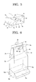
- FIG. 5 is a view describing an exemplary end face of large dimension of the container storage box of the present invention.
- FIG. 6 is a perspective view showing another exemplary container storage box of the present invention.
- FIG. 7 is a perspective view showing an exemplary container storage box according to the third embodiment of the present invention.
- FIG. 8A is a view describing an exemplary deformable container suitable to be contained in the container storage box of the present invention.
- FIG. 8B is a view showing a folded condition of the deformable container of FIG. 8A .
- the container storage box of the present invention contains and stores a deformable container having a flexible region at least in part and is capable of discharging fluid content for image formation when placed in a container loading part of an image forming apparatus.
- the container storage box has a plurality of rigid sidewall faces which contain and store the deformable container while preventing random deformation of the deformable container and end faces of small and large dimension on top and bottom of the plurality of rigid sidewall faces and further has other composition as necessary.
- the rigid sidewall face regulate a configuration of the deformable container in a configuration accommodated in the container loading part while maintaining at least one of direction and position of the content outlet of the deformable container when the deformable container is placed in the image forming apparatus.
- At least one of the rigid sidewall faces contains at least two fold lines which are not parallel with one another and one of the top and bottom end faces except the plurality of rigid sidewall faces has a closing mechanism which is openable, closable and capable of being assembled and disassembled.
- the fold line is preferably placed in the sidewall faces in an angle enabling to fold the rigid sidewall faces deeper into the direction the inner volume of the container storage box narrows toward one of the top and bottom end faces.
- the material of the container storage box is not particularly limited and may be selected accordingly. Examples include general plate materials such as paperboard, etc., cardboard materials, and the like and of these, a cardboard material of E flute/K6 is particularly preferable.
- G flute is preferable in terms of the quality of material for the rigid sidewall face.
- Examples of the fluid content for image formation include toner, developer, and the like.
- FIG. 1 is an assembly drawing showing an exemplary container storage box according to the first embodiment of the present invention.
- the container storage box of FIG. 1 is used to contain, transport and store a deformable container having a flexible region at least in part and is capable of discharging fluid content for image formation when placed in a container loading part of an image forming apparatus.
- the deformable container (not shown) contains fluid content for image formation such as toner, developer, and the like and has an outlet for discharge.
- the container storage box of FIG. 1 is an exemplary hexahedron having a rigid sidewall face 1 which is in the back of FIG. 1 , a rigid sidewall face 2 which is in left hand side of FIG. 1 , a rigid sidewall face 3 which is in the front of FIG. 1 , a rigid sidewall face 4 which is in right hand side of FIG. 1 , and an end face 5 and an end face 6 which are on the top and bottom of the rigid sidewall faces.
- the end face 5 is an end face of small dimension and the end face 6 is an end face of large dimension.
- two sidewall faces of the plurality of sidewall faces 1 , 2 , 3 and 4 are in an angle narrowing toward the end face 5 of small dimension on closing side.
- the container storage box it is preferable for the container storage box to have an extension piece G at the end part of at least one of the top and bottom end faces, that is, the end part of the end face 5 of small dimension in FIG. 1B , because it can function as an antislip when piled up and as a finger-catch when a vertically positioned box is grabbed by hand.
- the rigid sidewall faces 1 , 2 , 3 and 4 regulate the configuration of the deformable container in a configuration accommodated in the container loading part while maintaining at least one of direction and position of the content outlet of the deformable container when the deformable container is placed in the image forming apparatus.
- the rigid sidewall face 2 has two fold lines 2 a and 2 b and the fold lines 2 a and 2 b are placed in the sidewall face 2 in an angle enabling to fold the rigid sidewall faces deeper into the direction the inner volume of the container storage box narrows toward the end face 5 of small dimension of the end faces 5 and 6 .
- the sidewall face 4 which faces the sidewall face 2 also has two fold lines 4 a and 4 b as in the exemplary container storage box.
- the folded sidewall faces are composed of two fold lines 2 a , 2 b , 4 a and 4 b which are stretched from the center of upper part toward both corners of the lower part.
- the container storage box of this example has a closing mechanism which is openable and closable on the end face 5 of small dimension of the top and bottom end faces 5 and 6 .
- this closing mechanism the end face 5 of small dimension is closed by folding the folding part 5 a placed at the tip of the sidewall face 3 in a direction from front to back of FIG. 1 , folding the folding part 5 d placed at the tip of the sidewall face 1 in a direction toward front of FIG.
- the folding part 5 a has an opening 5 c as a result of forming folding part 3 a and the insertion tongue-shaped piece 5 b.
- the end face 5 of small dimension is formed by placing the folding parts 5 a and 5 d on top of the other. (Furthermore, a portion of the end face 5 of small dimension is a threefold with the insertion tongue-shaped piece 5 b placed on top.)
- the folding part 5 a is firmly locked by the engagement of insertion tongue-shaped piece 5 e placed at the tip of the folding part 5 d and slit-like cutout 5 f and also by the engagement of insertion tongue-shaped piece 5 b and slid edge 5 g and still can be unlocked easily to open the end face 5 of small dimension.
- the relation between dimension S A of the end face on the closing side and dimension S B of the end face on non-closing side (opposing end face) is S A ⁇ S B .
- the closing mechanism of the present invention is not necessary be elaborate like this, and folding part 5 a or insertion tongue-shaped piece 5 b which engages with the slit-like cutout 5 g or insertion tongue-shaped piece 5 e which engages with the slit-like cutout 5 f may be omitted.
- this kind of closing mechanism can be disposed on the end face 6 of large dimension as well as on the end face 5 of small dimension. Or, the closing mechanism can be disposed on the end face 6 instead of on the end face 5 .
- FIG. 3A is an assembly drawing showing an exemplary container storage box according to the second embodiment of the present invention.
- the container storage box of this example is also a hexahedron having 4 rigid sidewall faces 1 , 2 , 3 and 4 which include a rigid sidewall face 1 which is in the back of FIG. 3A , a rigid sidewall face 2 which is in left hand side of FIG. 3A , a rigid sidewall face 3 which is in the front of FIG. 3A and a rigid sidewall face 4 which is in right hand side of FIG. 3A , and an end face 5 of small dimension and an end face 6 of large dimension which are placed at the top and bottom of the rigid sidewall faces.
- openable and closable closing mechanism is not shown in FIG. 3A .
- the relation between dimension S C of the end face placed in closing side and dimension S D of the end face placed in non-closing side (opposing end face) is S C ⁇ S D .
- fold lines 2 a , 2 b , 4 a and 4 b are branched from the center of upper part of the sidewall faces 2 and 4 and stretched to the extent not reaching the lower part of the sidewall face of the container storage box. Therefore, the form of the container storage box has a mechanism of folding in both sides of the sidewall faces 2 and 4 in a portion short of the lower part.
- fold lines 2 a , 2 b , 4 a and 4 b described here are extreme ones which are branched from the center of upper part of the sidewall faces 2 and 4 , however, it is possible to make appropriate gaps between end parts of fold lines 2 a , 2 b , 4 a and 4 b in the upper part of the sidewall faces 2 and 4 or it is also possible to have no gaps depending on the size of an outlet of fluid content of the deformable container contained in the container storage box, cap size or the height of the deformable container.
- the container storage boxes of these aspects are included as preferred examples of the container storage box.
- the container storage box it is preferable for the container storage box to have a extension piece G at the end part of at least one of the top and bottom end faces, that is, the end part of the end face 5 of small dimension in FIG. 3B , because it can function as an antislip when piled up and also as a finger-catch when a vertically positioned box is grabbed by hand.
- the extension piece G which remains unfolded when fold lines are folded is disposed on the folding part 5 d of the end face 5 of small dimension to have an extending portion after the box is assembled.
- An engagement slit 3 b is disposed on the folding part of the sidewall face 3 for the engagement with the extension piece G.
- slip drop of upper container storage box can be prevented when the container storage box of the present invention is piled up by the engagement of the extension piece G and the engagement slit 3 b . Also slip drop of upper container storage box can be similarly prevented by stacking the boxes in a way that the extension piece G is hooked to the outside of the end face 6 of large dimension while omitting the disposal of the engagement slit 3 b (not shown).
- one of the sidewall faces 1 and 3 and the end faces 5 and 6 are perpendicular to each other while other sidewall face takes the form of an acute angle so that the piled container storage boxes are in the form of cuboids.
- this is not mandatory for this invention.
- an end face 6 of large dimension with a combination of two symmetric bed-type end-face framing pieces 6 b and 6 g and the end face 6 of large dimension, an opposing end face, to be a bottom part in this invention.
- the bed-type sidewall framing piece 6 b contains a diagonal fold line 6 d of a head region 6 c , an insertion tongue-shaped piece 6 e of the side and adjacent receiving concave part 6 f .
- the bed-type sidewall framing piece 6 g contains a diagonal fold line 6 i of head region 6 h , an insertion tongue-shaped piece 6 j of the side and adjacent receiving concave part 6 k .
- the end-face framing pieces 6 b and 6 g are engaged by one-touch operation by inserting each insertion tongue-shaped piece 6 e and 6 j into the opposing receiving concave parts 6 k and 6 f . It can be disengaged by one-touch operation by pressing the portion of diagonal fold lines 6 d and 6 i of the head part toward the inside of the container storage box.
- the strength of the end-face framing piece 6 b can be appropriately improved by bonding the rigid sidewall material placed at the tip of the sidewall face 3 as an extension and the rigid sidewall material placed at the tip of the sidewall face 2 as an extension.
- strength of the end-face framing piece 6 g can also be appropriately improved by bonding the rigid sidewall material placed at the tip of the sidewall face 1 as an extension and the rigid sidewall material placed at the tip of the sidewall face 4 as an extension.
- the end face 6 of large dimension of the container storage box of the present invention is not particularly limited and may be selected accordingly. It may be composed of 4 end-face framing pieces 6 m , 6 n , 6 p and 6 q as shown in FIG. 6 , for example.
- the container storage box according to the third embodiment of the present invention is shown in FIG. 7 .
- tongue-shaped piece 2 d is placed at the end part of narrower side of the sidewall face 2 and tongue-shaped piece 4 d is placed at the end part of narrower side of the sidewall face 4 instead of having the folding part 5 a as in the examples shown in FIGS. 1A and 1B .
- the insertion tongue-shaped piece 5 e placed at the tip of the folding part 5 d as one element forming the end face 5 of small dimension can be satisfactory larger than that of the first embodiment shown in FIGS. 1A and 1B .
- the third embodiment is similar to the first embodiment except for above points and the explanation is omitted.
- a cardboard of E flute/K6 was used for the material of the container storage box according to these embodiments of the present invention.
- the material is not limited to above and it may be a cardboard material in general.
- a toner cartridge was assigned as a deformable container and the size of bottom surface of these exemplary container storage boxes was set to 85 mm ⁇ 120 mm which is the size fitted to be placed in the main body of an apparatus for the purpose of regulating it to not to expand to the size impossible to be placed in the main body of the image forming apparatus by deformation. Meanwhile, the size of bottom surface of the container storage box is not limited to above because interior content changes depending on the main body of the image forming apparatus and toner color.
- FIGS. 8A and 8B an exemplary deformable container which is suitable to be contained in the container storage box of the present invention, having a flexible region at least in part and capable of discharging fluid content for image formation when placed in a container loading part of an image forming apparatus will be explained.
- the deformable container as shown in FIG. 8A is a soft type and composed of a bag part 20 which expands in the form of cuboids and a square-pyramid part 21 which is connected to the bag part 20 and a content outlet 22 placed in the most narrow part.
- the flexible material composing bag part include plastic sheets such as polyester, polyethylene, polyurethane, polypropylene and nylon resin, etc. or paper, and the like processed as a single layer or a multilayer of different materials and also include resin-coated paper, for example.
- two of the layer is made of resin, it is preferably tear resistant against the external pressure and the inside is preferably made of relatively soft materials such as intermediate/high pressure polyethylene and outside is preferably made of relatively hard materials such as nylon resin.
- the flexible material may be vapor deposited with aluminum or may be loaded with an antistatic agent to prevent static.
- the thickness of flexible material is not particularly limited and it is preferably 20 ⁇ m to 200 ⁇ m and more preferably 80 ⁇ m to 150 ⁇ m. When it is too thick, advantageous effect of being flexible material cannot be obtained and when it is too thin, the part filled with toner sags and discharge of toner may not be performed satisfactory.
- the soft type container of the present invention is a toner container, it also includes the toner container with bag part and outlet which are independent and capable of connecting and separating.
- the volume average particle diameter of toner particle is preferably 2.5 ⁇ m to 15 ⁇ m, more preferably 3.0 ⁇ m to 12.0 ⁇ m and most preferably 5.0 ⁇ m to 9.0 ⁇ m.
- the absolute specific gravity of toner is preferably 1.02 to 1.45 and more preferably 1.1 to 1.3.
- the filling density of toner is preferably 0.20 g/cm 3 to 0.90 g/cm 3 and more preferably 0.35 g/cm 3 to 0.85 g/cm 3 .
- a structure which can secure the sealed condition when connected a screw structure or a joint structure, for example, and at least opening part of the bag part is preferably composed of relatively thick flexible material for above purpose.
- the bag part has an opening part which is to be fixed with an outlet part. Furthermore, a bag part with a seam which is formed by bonding the prepared plural material pieces which are flexible by heat sealing, etc. to form a predetermined shape of a container or when the flexible material is a plastic resin, a bag part with no seams which is formed into a predetermined shape of a container by integral mounding of tube extrusion is used. As described above, a bag part not entirely composed of flexible material but partly composed of rigid material is also included.
- a tubular body which makes up an outlet is composed of plastic material such as polyethylene and polypropylene or metals and is relatively rigid, and it is preferable that the material is at least identical with or related to the material making up the bag part for obtaining appropriate fixation result.
- the tubular body can be classified broadly into joint part with nozzles, etc. and fixation part fixed with an opening part of the bag part and inner diameter and structure can be altered corresponding to the purpose of each portion.
- the deformable container as shown in FIG. 8A can be folded thinly in the form of approximately flat plate at the bottom fold lines 10 , 11 , 12 , 13 and 14 and side fold line 15 and can be rolled up slimly as shown in FIG. 8B .
- the bottom portion does not form an approximately flat plate unless folded at the bottom fold lines 10 , 11 , 12 , 13 and 14 .
- the square pyramid part 21 becomes thin in the form of approximately flat plate by only being folded at side fold line 15 , it is likely to be bulky toward the bottom. In consequence, it is suitable for being contained in the container storage box of the present invention having above structure, however, if it is a container in the form of bag which is flexible, the present invention is not particularly limited to above structure.
- the fold lines 2 a , 2 b , 4 a and 4 b on the side of the container storage box of the present invention are preferably placed from inside and outside of the container storage box. As a result, it is easily folded and assembled during manufacture of the container storage box.
- the strength of the container storage box increases by using a cardboard with the flutes running in lateral direction.
- the container storage box of the present invention When the container storage box of the present invention is stored vertically with the end face of large dimension down, the refilling ability is improved. This is because the box is reversed at the time of use.
- the container storage box of the present invention can be used as a collecting box of used toner cartridge. It is also preferable to wrap a belt-like film around the periphery side of the container storage box of the present invention. By wrapping the belt-like film around the periphery side, it is possible to fix the container storage box or to fix the deformable container contained inside while suppressing the force of the deformable container to prevent it from opening itself. It becomes also tough against the fall. Furthermore, it is preferable that the film which fixes the container storage box of the present invention is printed. By using the film as a display label, printing on the container storage box can be eliminated and standardizing of the container storage box is possible.
- the various slits for each flap insertion such as engagement slit 3 b for the slit-like cutout G, the slit-like cutout 5 g for the insertion tongue-like piece 5 b , etc., for example, are cut off at a depth of 1 mm to 20 mm.
- a cutoff line of 1 mm to 5 mm length on the sidewall face of the container storage box of the present invention.
- a cutoff line of 1 mm to 5 mm on the sidewall face of the container storage box it is easily folded and assembled at the time of manufacture.
- the various slits for flap insertion such as engagement slit 3 b for the slit-like cutout G, the slit-like cutout 5 g for the insertion tongue-like piece 5 b , the slit-like cutout 5 f for the insertion tongue-like piece 5 e , etc., for example, have an opening of 20 mm to 100 mm in width.
- the inner volume of the container storage box of the present invention is preferably 1.1 to 1.5 based on the volume of the deformable container which is 1.
- each flap insertion tongue-shaped piece
- the end form of each flap is preferably in a circular form and not in an angular form and is preferably 5 mm to 40 mm in radius.
- the end form of flaps is 5 mm to 40 mm in radius, it becomes easier to assemble at the time of manufacture.
- the container storage box of the present invention and the deformable container contained in the container storage box have been explained in detail above.
- the present invention is not limited to above embodiments and making various changes is allowed as long as it does not deviate from the summary of the present invention.
- the container storage box of the present invention can suppress the deformation of a container during transportation and storage and the deformation associated with the solidification of contents; does not affect the setting of the container to the main body of an image forming apparatus; and can protect and fix the container without the use of cushioning material, it is suitably used for various image forming apparatuses.
Abstract
Description
Claims (19)
Applications Claiming Priority (3)
| Application Number | Priority Date | Filing Date | Title |
|---|---|---|---|
| JP2004-372179 | 2004-12-22 | ||
| JP2004372179A JP4584701B2 (en) | 2004-12-22 | 2004-12-22 | Container storage box for easily deformable containers containing powder for image formation |
| PCT/JP2005/024006 WO2006068296A1 (en) | 2004-12-22 | 2005-12-21 | Container storage box for deformable container containing fine particles for image formation |
Publications (2)
| Publication Number | Publication Date |
|---|---|
| US20080265009A1 US20080265009A1 (en) | 2008-10-30 |
| US8033447B2 true US8033447B2 (en) | 2011-10-11 |
Family
ID=36601880
Family Applications (1)
| Application Number | Title | Priority Date | Filing Date |
|---|---|---|---|
| US11/722,614 Expired - Fee Related US8033447B2 (en) | 2004-12-22 | 2005-12-21 | Container storage box for deformable container containing fine particles for image formation |
Country Status (6)
| Country | Link |
|---|---|
| US (1) | US8033447B2 (en) |
| EP (1) | EP1836537B1 (en) |
| JP (1) | JP4584701B2 (en) |
| KR (1) | KR100895655B1 (en) |
| CN (1) | CN101088051B (en) |
| WO (1) | WO2006068296A1 (en) |
Cited By (13)
| Publication number | Priority date | Publication date | Assignee | Title |
|---|---|---|---|---|
| US20110069997A1 (en) * | 2009-09-18 | 2011-03-24 | Fuji Xerox Co., Ltd. | Developer container package body and package container |
| US20150360821A1 (en) * | 2014-06-11 | 2015-12-17 | Hugh Greenwood | Reusable mailer bag |
| US20190054693A1 (en) * | 2016-05-12 | 2019-02-21 | Hewlett-Packard Development Company, L.P. | Build material containers |
| USD860807S1 (en) | 2018-04-18 | 2019-09-24 | Inno-Pak, Llc | Tamper evident bag |
| US20200231354A1 (en) * | 2017-02-16 | 2020-07-23 | Nwb Finland Oy | Box for bag-in-box package |
| US10737843B2 (en) | 2014-06-11 | 2020-08-11 | Green 2 Green Products, Inc. | Reusable mailer bag |
| US10974892B1 (en) * | 2017-03-28 | 2021-04-13 | Monroe Zafir | Intermediate bulk container cartridge |
| USD949010S1 (en) | 2019-09-25 | 2022-04-19 | Inno-Pak, Llc | Tamper evident bag seal |
| USD949686S1 (en) | 2019-09-25 | 2022-04-26 | Inno-Pak, Llc | Tamper-evident bag seal |
| US11358754B2 (en) | 2019-09-25 | 2022-06-14 | Inno-Pak, Llc | Tamper-evident bag seal and tamper-evident bags and methods |
| USD970339S1 (en) | 2019-09-25 | 2022-11-22 | Inno-Pak, Llc | Tamper-evident bag seal |
| US11548690B2 (en) | 2020-11-13 | 2023-01-10 | Inno-Pak, Llc | Tamper-evident bag seal with tabs and methods of use |
| US11760532B2 (en) | 2020-04-30 | 2023-09-19 | Inno-Pak, Llc | Tamper evident carton |
Families Citing this family (8)
| Publication number | Priority date | Publication date | Assignee | Title |
|---|---|---|---|---|
| WO2011028824A1 (en) * | 2009-09-02 | 2011-03-10 | Monosol Rx, Llc | Unit assembly and method of making same |
| US8720769B2 (en) | 2009-09-15 | 2014-05-13 | Packaging Corporation Of America | Beverage container |
| JP5948430B2 (en) * | 2011-11-08 | 2016-07-06 | アマゾン テクノロジーズ インコーポレイテッド | Bag transport system and method |
| JP5808233B2 (en) * | 2011-11-29 | 2015-11-10 | キヤノン株式会社 | Developer storage unit, developing device, process cartridge, electrophotographic image forming apparatus |
| WO2017194138A1 (en) * | 2016-05-12 | 2017-11-16 | Hewlett-Packard Development Company, L.P. | Build material container, and collection tube structure |
| US10919680B1 (en) | 2018-10-08 | 2021-02-16 | Packaging Corporation Of America | Liquid beverage container |
| USD907295S1 (en) * | 2019-06-14 | 2021-01-05 | Kwanghyun BAEK | Cosmetic carton |
| FR3135257A1 (en) * | 2022-05-04 | 2023-11-10 | Ds Smith Packaging France | Transportable and stackable packaging |
Citations (21)
| Publication number | Priority date | Publication date | Assignee | Title |
|---|---|---|---|---|
| US3481524A (en) * | 1967-12-18 | 1969-12-02 | Packaging Corp America | Container with pouring spout |
| US3534898A (en) * | 1968-08-06 | 1970-10-20 | Continental Can Co | Carton with removable identification sleeve |
| US3955749A (en) * | 1974-06-28 | 1976-05-11 | Eugene Turkenkopf | Expansible envelope |
| US4243171A (en) * | 1978-05-25 | 1981-01-06 | Prin Jean Claude | Carrier for packing and carrying articles |
| JPS6035765A (en) | 1983-03-17 | 1985-02-23 | インタ−ナショナル ビジネス マシ−ンズ コ−ポレ−ション | Developer mixture conveying/servicing container |
| JPS6231021A (en) | 1985-08-01 | 1987-02-10 | Fuji Photo Film Co Ltd | Magnetic recording medium |
| US4734288A (en) * | 1984-11-29 | 1988-03-29 | E. A. Sween Company | Package for expandable food product |
| JPH0315672A (en) | 1989-03-27 | 1991-01-24 | Nippondenso Co Ltd | Radial piston pump |
| US5042714A (en) * | 1989-08-17 | 1991-08-27 | Hall John B | Collapsible grocery container |
| US5083700A (en) * | 1990-06-15 | 1992-01-28 | Bil Mar Foods, Inc. | Triangular cross-section package |
| JPH06183435A (en) | 1992-12-24 | 1994-07-05 | Konica Corp | Corrugated cardboard case |
| JPH0740427A (en) | 1993-07-26 | 1995-02-10 | Toyo Seikan Kaisha Ltd | Rotary extrusion blow molding machine |
| CN2427445Y (en) | 2000-06-27 | 2001-04-25 | 嘉年华(天津)国际有限公司 | Hand carried box with inward-folding end closure |
| US6253995B1 (en) * | 2000-05-16 | 2001-07-03 | Burrows Paper Corporation | Insulated containers and sidewalls having laterally extending flutes, and methods |
| US6478216B2 (en) * | 1999-12-20 | 2002-11-12 | Dailycer | Packaging suitable for food products and cut-out blank for forming it |
| WO2003082685A1 (en) | 2002-03-26 | 2003-10-09 | Stephen Mulcahy | Improvements in and relating to corrugated cardboard supports |
| JP2005206242A (en) | 2003-09-30 | 2005-08-04 | Ricoh Co Ltd | Container storage box for deformable container containing fine particles for image formation |
| US20060002743A1 (en) | 2004-04-23 | 2006-01-05 | Goro Katsuyama | Apparatuses for image forming capable of effectively conveying developer therefrom and a method of effectively forming a reinforcing member adhering to the apparatuses |
| US20060144746A1 (en) * | 2003-12-18 | 2006-07-06 | Ricoh Company, Limited | Packaging box |
| US20070140747A1 (en) | 2004-11-09 | 2007-06-21 | Emi Kita | Toner container, toner supply device and image forming apparatus |
| US20070241900A1 (en) * | 2004-03-25 | 2007-10-18 | Tatsuo Sasazaki | Sheet-Like Formed Material |
Family Cites Families (11)
| Publication number | Priority date | Publication date | Assignee | Title |
|---|---|---|---|---|
| JPH0234181Y2 (en) * | 1985-08-09 | 1990-09-13 | ||
| JPH0339149Y2 (en) | 1986-03-20 | 1991-08-19 | ||
| JPH06231021A (en) * | 1993-02-05 | 1994-08-19 | Nec Software Ltd | Data managing system provided with data generation information |
| GB9317263D0 (en) * | 1993-08-19 | 1993-10-06 | Wrekin Packaging Solutions Lim | A carton |
| JPH0740427U (en) * | 1993-12-28 | 1995-07-18 | ニッキ工業株式会社 | Folding paper container |
| JP3015672U (en) * | 1995-03-10 | 1995-09-05 | 日本コパック株式会社 | Cardboard returnable case coated with a release agent |
| JPH10161498A (en) * | 1996-11-28 | 1998-06-19 | Dainippon Printing Co Ltd | Toner recovering container |
| JP2000194182A (en) * | 1998-10-19 | 2000-07-14 | Ricoh Co Ltd | Toner container and image forming device using the same |
| SG156515A1 (en) * | 1998-12-22 | 2009-11-26 | Ricoh Kk | Toner container and image forming method and apparatus using the same |
| CN2423208Y (en) * | 2000-03-16 | 2001-03-14 | 嘉年华(天津)国际有限公司 | Quick expansiion formed carton |
| JP2003237838A (en) | 2002-02-14 | 2003-08-27 | Fuji Seal Inc | Outer packaging case of bag-like container |
-
2004
- 2004-12-22 JP JP2004372179A patent/JP4584701B2/en not_active Expired - Fee Related
-
2005
- 2005-12-21 KR KR1020077016709A patent/KR100895655B1/en active IP Right Grant
- 2005-12-21 EP EP05822762.0A patent/EP1836537B1/en not_active Expired - Fee Related
- 2005-12-21 US US11/722,614 patent/US8033447B2/en not_active Expired - Fee Related
- 2005-12-21 CN CN2005800443507A patent/CN101088051B/en active Active
- 2005-12-21 WO PCT/JP2005/024006 patent/WO2006068296A1/en active Application Filing
Patent Citations (23)
| Publication number | Priority date | Publication date | Assignee | Title |
|---|---|---|---|---|
| US3481524A (en) * | 1967-12-18 | 1969-12-02 | Packaging Corp America | Container with pouring spout |
| US3534898A (en) * | 1968-08-06 | 1970-10-20 | Continental Can Co | Carton with removable identification sleeve |
| US3955749A (en) * | 1974-06-28 | 1976-05-11 | Eugene Turkenkopf | Expansible envelope |
| US4243171A (en) * | 1978-05-25 | 1981-01-06 | Prin Jean Claude | Carrier for packing and carrying articles |
| JPS6035765A (en) | 1983-03-17 | 1985-02-23 | インタ−ナショナル ビジネス マシ−ンズ コ−ポレ−ション | Developer mixture conveying/servicing container |
| US4523615A (en) | 1983-03-17 | 1985-06-18 | International Business Machines Corporation | Method and apparatus for in situ purging a xerographic developer |
| US4734288A (en) * | 1984-11-29 | 1988-03-29 | E. A. Sween Company | Package for expandable food product |
| JPS6231021A (en) | 1985-08-01 | 1987-02-10 | Fuji Photo Film Co Ltd | Magnetic recording medium |
| JPH0315672A (en) | 1989-03-27 | 1991-01-24 | Nippondenso Co Ltd | Radial piston pump |
| US5042714A (en) * | 1989-08-17 | 1991-08-27 | Hall John B | Collapsible grocery container |
| US5083700A (en) * | 1990-06-15 | 1992-01-28 | Bil Mar Foods, Inc. | Triangular cross-section package |
| JPH06183435A (en) | 1992-12-24 | 1994-07-05 | Konica Corp | Corrugated cardboard case |
| JPH0740427A (en) | 1993-07-26 | 1995-02-10 | Toyo Seikan Kaisha Ltd | Rotary extrusion blow molding machine |
| US6478216B2 (en) * | 1999-12-20 | 2002-11-12 | Dailycer | Packaging suitable for food products and cut-out blank for forming it |
| US6253995B1 (en) * | 2000-05-16 | 2001-07-03 | Burrows Paper Corporation | Insulated containers and sidewalls having laterally extending flutes, and methods |
| CN2427445Y (en) | 2000-06-27 | 2001-04-25 | 嘉年华(天津)国际有限公司 | Hand carried box with inward-folding end closure |
| WO2003082685A1 (en) | 2002-03-26 | 2003-10-09 | Stephen Mulcahy | Improvements in and relating to corrugated cardboard supports |
| JP2005206242A (en) | 2003-09-30 | 2005-08-04 | Ricoh Co Ltd | Container storage box for deformable container containing fine particles for image formation |
| US20060191984A1 (en) * | 2003-09-30 | 2006-08-31 | Teruo Hitosugi | Container storage box for deformable container containing fine particles for image formation |
| US20060144746A1 (en) * | 2003-12-18 | 2006-07-06 | Ricoh Company, Limited | Packaging box |
| US20070241900A1 (en) * | 2004-03-25 | 2007-10-18 | Tatsuo Sasazaki | Sheet-Like Formed Material |
| US20060002743A1 (en) | 2004-04-23 | 2006-01-05 | Goro Katsuyama | Apparatuses for image forming capable of effectively conveying developer therefrom and a method of effectively forming a reinforcing member adhering to the apparatuses |
| US20070140747A1 (en) | 2004-11-09 | 2007-06-21 | Emi Kita | Toner container, toner supply device and image forming apparatus |
Cited By (19)
| Publication number | Priority date | Publication date | Assignee | Title |
|---|---|---|---|---|
| US20110069997A1 (en) * | 2009-09-18 | 2011-03-24 | Fuji Xerox Co., Ltd. | Developer container package body and package container |
| US8331831B2 (en) * | 2009-09-18 | 2012-12-11 | Fuji Xerox Co., Ltd. | Developer container package body and package container |
| US20150360821A1 (en) * | 2014-06-11 | 2015-12-17 | Hugh Greenwood | Reusable mailer bag |
| US10011394B2 (en) * | 2014-06-11 | 2018-07-03 | Green 2 Green Products, Inc. | Reusable mailer bag |
| US11312540B2 (en) * | 2014-06-11 | 2022-04-26 | Green 2 Green Products, Inc | Reusable mailer bag |
| US10737843B2 (en) | 2014-06-11 | 2020-08-11 | Green 2 Green Products, Inc. | Reusable mailer bag |
| US20190054693A1 (en) * | 2016-05-12 | 2019-02-21 | Hewlett-Packard Development Company, L.P. | Build material containers |
| US11254051B2 (en) * | 2016-05-12 | 2022-02-22 | Hewlett-Packard Development Company, L.P. | Build material containers |
| US10961037B2 (en) * | 2017-02-16 | 2021-03-30 | Nwb Finland Oy | Box for bag-in-box package |
| US20200231354A1 (en) * | 2017-02-16 | 2020-07-23 | Nwb Finland Oy | Box for bag-in-box package |
| US10974892B1 (en) * | 2017-03-28 | 2021-04-13 | Monroe Zafir | Intermediate bulk container cartridge |
| USD860807S1 (en) | 2018-04-18 | 2019-09-24 | Inno-Pak, Llc | Tamper evident bag |
| USD949010S1 (en) | 2019-09-25 | 2022-04-19 | Inno-Pak, Llc | Tamper evident bag seal |
| USD949686S1 (en) | 2019-09-25 | 2022-04-26 | Inno-Pak, Llc | Tamper-evident bag seal |
| US11358754B2 (en) | 2019-09-25 | 2022-06-14 | Inno-Pak, Llc | Tamper-evident bag seal and tamper-evident bags and methods |
| USD970339S1 (en) | 2019-09-25 | 2022-11-22 | Inno-Pak, Llc | Tamper-evident bag seal |
| USD1003711S1 (en) | 2019-09-25 | 2023-11-07 | Inno-Pak, Llc | Tamper-evident bag seal |
| US11760532B2 (en) | 2020-04-30 | 2023-09-19 | Inno-Pak, Llc | Tamper evident carton |
| US11548690B2 (en) | 2020-11-13 | 2023-01-10 | Inno-Pak, Llc | Tamper-evident bag seal with tabs and methods of use |
Also Published As
| Publication number | Publication date |
|---|---|
| EP1836537B1 (en) | 2018-08-15 |
| WO2006068296A1 (en) | 2006-06-29 |
| US20080265009A1 (en) | 2008-10-30 |
| JP2006176172A (en) | 2006-07-06 |
| EP1836537A1 (en) | 2007-09-26 |
| KR100895655B1 (en) | 2009-05-07 |
| CN101088051A (en) | 2007-12-12 |
| KR20070087677A (en) | 2007-08-28 |
| CN101088051B (en) | 2010-11-10 |
| JP4584701B2 (en) | 2010-11-24 |
| EP1836537A4 (en) | 2013-10-30 |
Similar Documents
| Publication | Publication Date | Title |
|---|---|---|
| US8033447B2 (en) | Container storage box for deformable container containing fine particles for image formation | |
| EP0868373B1 (en) | Flexible container for flowable materials | |
| US5158369A (en) | Stabilized flexible container for flowable materials | |
| US9016555B2 (en) | Flexible liner and bag-in-box container systems | |
| JP4584659B2 (en) | Container storage box for easily deformable containers containing powder for image formation | |
| JP6658835B2 (en) | Liquid storage container and folding method thereof | |
| US5230689A (en) | Method of making stabilized flexible container for flowable materials | |
| WO2014147425A2 (en) | Packaging | |
| US5779049A (en) | Bin loader package and method | |
| JPH0624487A (en) | Container for grain cargo material, fluid and equivalent item | |
| JP5390329B2 (en) | Fluid packaging container | |
| EP3583041B1 (en) | Box for bag-in-box package, blank therefore and bag-in-box package | |
| CN116507559A (en) | Cartridge blank, system and method | |
| JP2000085789A (en) | Synthetic resin bag with assist board | |
| TW201637954A (en) | Bend to open flat poly-pack tissue cassette for use in over-shell dispensers | |
| US20230356909A1 (en) | Retention packaging system | |
| JP7283113B2 (en) | Ink container and ink container package | |
| JP2004189313A (en) | Packaging method and packaging box for soft bag filled with liquid | |
| JPH08276957A (en) | Bag-in-box | |
| WO2007144930A1 (en) | Solidification/packing container of fluid matter | |
| WO2024072867A1 (en) | Self-standing foldable container apparatuses and methods of using the same | |
| JP2009137619A (en) | Package | |
| JP2003054538A (en) | Packaging box | |
| EP2108598A1 (en) | Bag-in-box packaging system for bulk flowable materials | |
| JP2008273541A (en) | Partition accommodated in container for transporting article |
Legal Events
| Date | Code | Title | Description |
|---|---|---|---|
| AS | Assignment |
Owner name: RICOH COMPANY, LTD., JAPAN Free format text: ASSIGNMENT OF ASSIGNORS INTEREST;ASSIGNOR:KATOH, KEISUKE;REEL/FRAME:020616/0078 Effective date: 20070710 |
|
| FEPP | Fee payment procedure |
Free format text: PAYOR NUMBER ASSIGNED (ORIGINAL EVENT CODE: ASPN); ENTITY STATUS OF PATENT OWNER: LARGE ENTITY |
|
| ZAAA | Notice of allowance and fees due |
Free format text: ORIGINAL CODE: NOA |
|
| ZAAB | Notice of allowance mailed |
Free format text: ORIGINAL CODE: MN/=. |
|
| STCF | Information on status: patent grant |
Free format text: PATENTED CASE |
|
| FPAY | Fee payment |
Year of fee payment: 4 |
|
| MAFP | Maintenance fee payment |
Free format text: PAYMENT OF MAINTENANCE FEE, 8TH YEAR, LARGE ENTITY (ORIGINAL EVENT CODE: M1552); ENTITY STATUS OF PATENT OWNER: LARGE ENTITY Year of fee payment: 8 |
|
| FEPP | Fee payment procedure |
Free format text: MAINTENANCE FEE REMINDER MAILED (ORIGINAL EVENT CODE: REM.); ENTITY STATUS OF PATENT OWNER: LARGE ENTITY |
|
| LAPS | Lapse for failure to pay maintenance fees |
Free format text: PATENT EXPIRED FOR FAILURE TO PAY MAINTENANCE FEES (ORIGINAL EVENT CODE: EXP.); ENTITY STATUS OF PATENT OWNER: LARGE ENTITY |
|
| STCH | Information on status: patent discontinuation |
Free format text: PATENT EXPIRED DUE TO NONPAYMENT OF MAINTENANCE FEES UNDER 37 CFR 1.362 |
|
| FP | Lapsed due to failure to pay maintenance fee |
Effective date: 20231011 |