US8028774B2 - Thick pointed superhard material - Google Patents
Thick pointed superhard material Download PDFInfo
- Publication number
- US8028774B2 US8028774B2 US12/625,728 US62572809A US8028774B2 US 8028774 B2 US8028774 B2 US 8028774B2 US 62572809 A US62572809 A US 62572809A US 8028774 B2 US8028774 B2 US 8028774B2
- Authority
- US
- United States
- Prior art keywords
- high impact
- impact resistant
- diamond
- resistant tool
- superhard material
- Prior art date
- Legal status (The legal status is an assumption and is not a legal conclusion. Google has not performed a legal analysis and makes no representation as to the accuracy of the status listed.)
- Active
Links
- 239000000463 material Substances 0.000 title claims abstract description 114
- 239000010432 diamond Substances 0.000 claims abstract description 75
- 229910003460 diamond Inorganic materials 0.000 claims abstract description 75
- 239000000758 substrate Substances 0.000 claims abstract description 62
- 229910052751 metal Inorganic materials 0.000 claims abstract description 46
- 239000002184 metal Substances 0.000 claims abstract description 46
- 239000011230 binding agent Substances 0.000 claims abstract description 12
- 239000010941 cobalt Substances 0.000 claims description 12
- 229910017052 cobalt Inorganic materials 0.000 claims description 12
- GUTLYIVDDKVIGB-UHFFFAOYSA-N cobalt atom Chemical group [Co] GUTLYIVDDKVIGB-UHFFFAOYSA-N 0.000 claims description 12
- 238000003801 milling Methods 0.000 claims description 10
- 239000010426 asphalt Substances 0.000 claims description 8
- 238000009527 percussion Methods 0.000 claims description 6
- 238000005065 mining Methods 0.000 claims description 5
- XUIMIQQOPSSXEZ-UHFFFAOYSA-N Silicon Chemical group [Si] XUIMIQQOPSSXEZ-UHFFFAOYSA-N 0.000 claims description 4
- 229910052710 silicon Inorganic materials 0.000 claims description 4
- 239000010703 silicon Substances 0.000 claims description 4
- 238000010586 diagram Methods 0.000 description 28
- UONOETXJSWQNOL-UHFFFAOYSA-N tungsten carbide Chemical group [W+]#[C-] UONOETXJSWQNOL-UHFFFAOYSA-N 0.000 description 8
- 239000011435 rock Substances 0.000 description 7
- 238000005553 drilling Methods 0.000 description 6
- 230000015572 biosynthetic process Effects 0.000 description 4
- 238000000576 coating method Methods 0.000 description 4
- 238000005755 formation reaction Methods 0.000 description 4
- 229910052582 BN Inorganic materials 0.000 description 3
- PZNSFCLAULLKQX-UHFFFAOYSA-N Boron nitride Chemical compound N#B PZNSFCLAULLKQX-UHFFFAOYSA-N 0.000 description 3
- 239000002585 base Substances 0.000 description 3
- 238000005452 bending Methods 0.000 description 3
- 239000011248 coating agent Substances 0.000 description 3
- 238000000034 method Methods 0.000 description 3
- 239000000203 mixture Substances 0.000 description 3
- XEEYBQQBJWHFJM-UHFFFAOYSA-N Iron Chemical compound [Fe] XEEYBQQBJWHFJM-UHFFFAOYSA-N 0.000 description 2
- PXHVJJICTQNCMI-UHFFFAOYSA-N Nickel Chemical compound [Ni] PXHVJJICTQNCMI-UHFFFAOYSA-N 0.000 description 2
- KDLHZDBZIXYQEI-UHFFFAOYSA-N Palladium Chemical compound [Pd] KDLHZDBZIXYQEI-UHFFFAOYSA-N 0.000 description 2
- NBIIXXVUZAFLBC-UHFFFAOYSA-N Phosphoric acid Chemical compound OP(O)(O)=O NBIIXXVUZAFLBC-UHFFFAOYSA-N 0.000 description 2
- 229910000831 Steel Inorganic materials 0.000 description 2
- 239000003082 abrasive agent Substances 0.000 description 2
- 230000009286 beneficial effect Effects 0.000 description 2
- 239000013078 crystal Substances 0.000 description 2
- 238000000227 grinding Methods 0.000 description 2
- -1 hydrate Chemical compound 0.000 description 2
- 230000002706 hydrostatic effect Effects 0.000 description 2
- 239000011159 matrix material Substances 0.000 description 2
- HBMJWWWQQXIZIP-UHFFFAOYSA-N silicon carbide Chemical compound [Si+]#[C-] HBMJWWWQQXIZIP-UHFFFAOYSA-N 0.000 description 2
- 229910010271 silicon carbide Inorganic materials 0.000 description 2
- 238000005245 sintering Methods 0.000 description 2
- 239000010959 steel Substances 0.000 description 2
- 229910052715 tantalum Inorganic materials 0.000 description 2
- GUVRBAGPIYLISA-UHFFFAOYSA-N tantalum atom Chemical compound [Ta] GUVRBAGPIYLISA-UHFFFAOYSA-N 0.000 description 2
- BVKZGUZCCUSVTD-UHFFFAOYSA-L Carbonate Chemical compound [O-]C([O-])=O BVKZGUZCCUSVTD-UHFFFAOYSA-L 0.000 description 1
- VYZAMTAEIAYCRO-UHFFFAOYSA-N Chromium Chemical compound [Cr] VYZAMTAEIAYCRO-UHFFFAOYSA-N 0.000 description 1
- 241000251729 Elasmobranchii Species 0.000 description 1
- 239000004593 Epoxy Substances 0.000 description 1
- 235000015842 Hesperis Nutrition 0.000 description 1
- 235000012633 Iberis amara Nutrition 0.000 description 1
- ZOKXTWBITQBERF-UHFFFAOYSA-N Molybdenum Chemical compound [Mo] ZOKXTWBITQBERF-UHFFFAOYSA-N 0.000 description 1
- ZCEAYPNEFSJYFM-UHFFFAOYSA-N OC(O)=O.OC(O)=O.OC(O)=O.P.P Chemical compound OC(O)=O.OC(O)=O.OC(O)=O.P.P ZCEAYPNEFSJYFM-UHFFFAOYSA-N 0.000 description 1
- NBIIXXVUZAFLBC-UHFFFAOYSA-L Phosphate ion(2-) Chemical compound OP([O-])([O-])=O NBIIXXVUZAFLBC-UHFFFAOYSA-L 0.000 description 1
- KJTLSVCANCCWHF-UHFFFAOYSA-N Ruthenium Chemical compound [Ru] KJTLSVCANCCWHF-UHFFFAOYSA-N 0.000 description 1
- 238000005299 abrasion Methods 0.000 description 1
- 229910052768 actinide Inorganic materials 0.000 description 1
- 150000001255 actinides Chemical class 0.000 description 1
- 229910052783 alkali metal Inorganic materials 0.000 description 1
- 150000001340 alkali metals Chemical class 0.000 description 1
- 229910000147 aluminium phosphate Inorganic materials 0.000 description 1
- 238000005219 brazing Methods 0.000 description 1
- 239000003054 catalyst Substances 0.000 description 1
- 239000004568 cement Substances 0.000 description 1
- 239000000919 ceramic Substances 0.000 description 1
- 238000006243 chemical reaction Methods 0.000 description 1
- 229910052804 chromium Inorganic materials 0.000 description 1
- 239000011651 chromium Substances 0.000 description 1
- 230000009194 climbing Effects 0.000 description 1
- 239000003245 coal Substances 0.000 description 1
- 230000006835 compression Effects 0.000 description 1
- 238000007906 compression Methods 0.000 description 1
- 230000007423 decrease Effects 0.000 description 1
- 230000032798 delamination Effects 0.000 description 1
- 230000000694 effects Effects 0.000 description 1
- 238000009313 farming Methods 0.000 description 1
- 238000005552 hardfacing Methods 0.000 description 1
- 150000004678 hydrides Chemical class 0.000 description 1
- XLYOFNOQVPJJNP-UHFFFAOYSA-M hydroxide Chemical compound [OH-] XLYOFNOQVPJJNP-UHFFFAOYSA-M 0.000 description 1
- 238000009863 impact test Methods 0.000 description 1
- 230000003116 impacting effect Effects 0.000 description 1
- 230000000977 initiatory effect Effects 0.000 description 1
- 229910052500 inorganic mineral Inorganic materials 0.000 description 1
- 229910052742 iron Inorganic materials 0.000 description 1
- 229910052747 lanthanoid Inorganic materials 0.000 description 1
- 150000002602 lanthanoids Chemical class 0.000 description 1
- WPBNNNQJVZRUHP-UHFFFAOYSA-L manganese(2+);methyl n-[[2-(methoxycarbonylcarbamothioylamino)phenyl]carbamothioyl]carbamate;n-[2-(sulfidocarbothioylamino)ethyl]carbamodithioate Chemical compound [Mn+2].[S-]C(=S)NCCNC([S-])=S.COC(=O)NC(=S)NC1=CC=CC=C1NC(=S)NC(=O)OC WPBNNNQJVZRUHP-UHFFFAOYSA-L 0.000 description 1
- 239000011707 mineral Substances 0.000 description 1
- 238000012986 modification Methods 0.000 description 1
- 230000004048 modification Effects 0.000 description 1
- 229910052750 molybdenum Inorganic materials 0.000 description 1
- 239000011733 molybdenum Substances 0.000 description 1
- 239000010813 municipal solid waste Substances 0.000 description 1
- 229910052759 nickel Inorganic materials 0.000 description 1
- 229910052758 niobium Inorganic materials 0.000 description 1
- 239000010955 niobium Substances 0.000 description 1
- GUCVJGMIXFAOAE-UHFFFAOYSA-N niobium atom Chemical compound [Nb] GUCVJGMIXFAOAE-UHFFFAOYSA-N 0.000 description 1
- 229910052755 nonmetal Inorganic materials 0.000 description 1
- 229910052763 palladium Inorganic materials 0.000 description 1
- TWHXWYVOWJCXSI-UHFFFAOYSA-N phosphoric acid;hydrate Chemical compound O.OP(O)(O)=O TWHXWYVOWJCXSI-UHFFFAOYSA-N 0.000 description 1
- 229910001392 phosphorus oxide Inorganic materials 0.000 description 1
- 230000001681 protective effect Effects 0.000 description 1
- 229910052703 rhodium Inorganic materials 0.000 description 1
- 239000010948 rhodium Substances 0.000 description 1
- MHOVAHRLVXNVSD-UHFFFAOYSA-N rhodium atom Chemical compound [Rh] MHOVAHRLVXNVSD-UHFFFAOYSA-N 0.000 description 1
- 238000005096 rolling process Methods 0.000 description 1
- 229910052707 ruthenium Inorganic materials 0.000 description 1
- 238000004901 spalling Methods 0.000 description 1
- 239000000126 substance Substances 0.000 description 1
- 230000002195 synergetic effect Effects 0.000 description 1
- VSAISIQCTGDGPU-UHFFFAOYSA-N tetraphosphorus hexaoxide Chemical compound O1P(O2)OP3OP1OP2O3 VSAISIQCTGDGPU-UHFFFAOYSA-N 0.000 description 1
- XLYOFNOQVPJJNP-UHFFFAOYSA-N water Chemical compound O XLYOFNOQVPJJNP-UHFFFAOYSA-N 0.000 description 1
- 239000002023 wood Substances 0.000 description 1
Images


Classifications
-
- E—FIXED CONSTRUCTIONS
- E21—EARTH DRILLING; MINING
- E21B—EARTH DRILLING, e.g. DEEP DRILLING; OBTAINING OIL, GAS, WATER, SOLUBLE OR MELTABLE MATERIALS OR A SLURRY OF MINERALS FROM WELLS
- E21B10/00—Drill bits
- E21B10/46—Drill bits characterised by wear resisting parts, e.g. diamond inserts
- E21B10/56—Button-type inserts
- E21B10/567—Button-type inserts with preformed cutting elements mounted on a distinct support, e.g. polycrystalline inserts
- E21B10/573—Button-type inserts with preformed cutting elements mounted on a distinct support, e.g. polycrystalline inserts characterised by support details, e.g. the substrate construction or the interface between the substrate and the cutting element
- E21B10/5735—Interface between the substrate and the cutting element
-
- E—FIXED CONSTRUCTIONS
- E21—EARTH DRILLING; MINING
- E21B—EARTH DRILLING, e.g. DEEP DRILLING; OBTAINING OIL, GAS, WATER, SOLUBLE OR MELTABLE MATERIALS OR A SLURRY OF MINERALS FROM WELLS
- E21B10/00—Drill bits
- E21B10/46—Drill bits characterised by wear resisting parts, e.g. diamond inserts
- E21B10/56—Button-type inserts
- E21B10/567—Button-type inserts with preformed cutting elements mounted on a distinct support, e.g. polycrystalline inserts
- E21B10/5673—Button-type inserts with preformed cutting elements mounted on a distinct support, e.g. polycrystalline inserts having a non planar or non circular cutting face
-
- E—FIXED CONSTRUCTIONS
- E21—EARTH DRILLING; MINING
- E21B—EARTH DRILLING, e.g. DEEP DRILLING; OBTAINING OIL, GAS, WATER, SOLUBLE OR MELTABLE MATERIALS OR A SLURRY OF MINERALS FROM WELLS
- E21B10/00—Drill bits
- E21B10/46—Drill bits characterised by wear resisting parts, e.g. diamond inserts
- E21B10/56—Button-type inserts
- E21B10/567—Button-type inserts with preformed cutting elements mounted on a distinct support, e.g. polycrystalline inserts
- E21B10/5676—Button-type inserts with preformed cutting elements mounted on a distinct support, e.g. polycrystalline inserts having a cutting face with different segments, e.g. mosaic-type inserts
Definitions
- the invention relates to a high impact resistant tool that may be used in machinery such as crushers, picks, grinding mills, roller cone bits, rotary fixed cutter bits, earth boring bits, percussion bits or impact bits, and drag bits. More particularly, the invention relates to inserts comprised of a carbide substrate with a non-planar interface and an abrasion resistant layer of superhard material affixed thereto using a high pressure high temperature press apparatus.
- Cutting elements and inserts for use in machinery such as crushers, picks, grinding mills, roller cone bits, rotary fixed cutter bits, earth boring bits, percussion bits or impact bits, and drag bits typically comprise a superhard material layer or layers formed under high temperature and pressure conditions, usually in a press apparatus designed to create such conditions, cemented to a carbide substrate containing a metal binder or catalyst such as cobalt.
- the substrate is often softer than the superhard material to which it is bound.
- Some examples of superhard materials that high pressure-high temperature (HPHT) presses may produce and sinter include cemented ceramics, diamond, polycrystalline diamond, and cubic boron nitride.
- a cutting element or insert is normally fabricated by placing a cemented carbide substrate into a container or cartridge with a layer of diamond crystals or grains loaded into the cartridge adjacent one face of the substrate.
- a number of such cartridges are typically loaded into a reaction cell and placed in the high pressure high temperature press apparatus.
- the substrates and adjacent diamond crystal layers are then compressed under HPHT conditions, which promotes a sintering of the diamond grains to form a polycrystalline diamond structure.
- the diamond grains become mutually bonded to form a diamond layer over the substrate interface.
- the diamond layer is also bonded to the substrate interface.
- Such inserts are often subjected to intense forces, torques, vibration, high temperatures and temperature differentials during operation. As a result, stresses within the structure may begin to form. Drill bits, for example, may exhibit stresses aggravated by drilling anomalies during well boring operations, such as bit whirl or bounce. These stresses often result in spalling, delamination, or fracture of the superhard abrasive layer or the substrate, thereby reducing or eliminating the cutting elements' efficacy and the life of the drill bit.
- the superhard material layer of an insert sometimes delaminates from the carbide substrate after the sintering process as well as during percussive and abrasive use. Damage typically found in percussive and drag drill bits may be a result of shear failure, although non-shear modes of failure are not uncommon.
- the interface between the superhard material layer and substrate is particularly susceptible to non-shear failure modes due to inherent residual stresses.
- U.S. Pat. No. 5,544,713 by Dennis which is herein incorporated by reference for all that it contains, discloses a cutting element which has a metal carbide stud having a conic tip formed with a reduced diameter hemispherical outer tip end portion of said metal carbide stud.
- the tip is shaped as a cone and is rounded at the tip portion. This rounded portion has a diameter which is 35-60% of the diameter of the insert.
- U.S. Pat. No. 5,848,657 by Flood et al. which is herein incorporated by reference for all that it contains, discloses domed polycrystalline diamond cutting element wherein a hemispherical diamond layer is bonded to a tungsten carbide substrate, commonly referred to as a tungsten carbide stud.
- the inventive cutting element includes a metal carbide stud having a proximal end adapted to be placed into a drill bit and a distal end portion. A layer of cutting polycrystalline abrasive material is disposed over said distal end portion such that an annulus of metal carbide adjacent and above said drill bit is not covered by said abrasive material layer.
- U.S. Pat. No. 4,109,737 by Bovenkerk which is herein incorporated by reference for all that it contains, discloses a rotary drill bit for rock drilling comprising a plurality of cutting elements held by and interference-fit within recesses in the crown of the drill bit.
- Each cutting element comprises an elongated pin with a thin layer of polycrystalline diamond bonded to the free end of the pin.
- a high impact resistant tool has a superhard material bonded to a cemented metal carbide substrate at a non-planar interface.
- the substrate has a tapered surface starting from a cylindrical rim of the substrate and ending at an elevated flatted central region formed in the substrate.
- the superhard material has a pointed geometry with a sharp apex having 0.050 to 0.125 inch radius of curvature.
- the superhard material also has a 0.100 to 0.500 inch thickness from the apex to the flatted central region of the substrate.
- the substrate may have a non-planar interface.
- the interface may comprise a slight convex geometry or a portion of the substrate may be slightly concave at the interface.
- the substantially pointed geometry may comprise a side which forms a 35 to 55 degree angle with a central axis of the tool.
- the angle may be substantially 45 degrees.
- the substantially pointed geometry may comprise a convex and/or a concave side.
- the radius may be 0.090 to 0.110 inches.
- the thickness from the apex to the non-planar interface may be 0.125 to 0.275 inches.
- the substrate may be bonded to an end of a carbide segment.
- the carbide segment may be brazed or press fit to a steel body.
- the substrate may comprise a 1 to 40 percent concentration of cobalt by weight.
- a tapered surface of the substrate may be concave and/or convex. The taper may incorporate nodules, grooves, dimples, protrusions, reverse dimples, or combinations thereof.
- the substrate has a central flatted region with a diameter of 0.125 to 0.250 inches.
- the superhard material and the substrate may comprise a total thickness of 0.200 to 0.700 inches from the apex to a base of the substrate. In some embodiments, the total thickness may be up to 2 inches.
- the superhard material may comprise diamond, polycrystalline diamond, natural diamond, synthetic diamond, vapor deposited diamond, silicon bonded diamond, cobalt bonded diamond, thermally stable diamond, polycrystalline diamond with a binder concentration of 1 to 40 percent by weight, infiltrated diamond, layered diamond, monolithic diamond, polished diamond, course diamond, fine diamond, cubic boron nitride, diamond impregnated matrix, diamond impregnated carbide, metal catalyzed diamond, or combinations thereof.
- a volume of the superhard material may be 75 to 150 percent of a volume of the carbide substrate.
- the volume of diamond may be up to twice as much as the volume of the carbide substrate.
- the superhard material may be polished.
- the superhard material may be a polycrystalline superhard material with an average grain size of 1 to 100 microns.
- the superhard material may comprise a concentration of binding agents of 1 to 40 percent by weight.
- the tool of the present invention comprises the characteristic of withstanding impacts greater than 80 joules.
- the high impact tool may be incorporated in drill bits, percussion drill bits, roller cone bits, shear bits, milling machines, indenters, mining picks, asphalt picks, cone crushers, vertical impact mills, hammer mills, jaw crushers, asphalt bits, chisels, trenching machines, or combinations thereof.
- FIG. 1 is a perspective diagram of an embodiment of a high impact resistant tool.
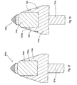
- FIG. 2 is a cross-sectional diagram of an embodiment of a tip with a pointed geometry.
- FIG. 2 a is a cross-sectional diagram of another embodiment a tip with a pointed geometry.
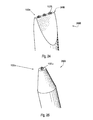
- FIG. 3 is a cross-sectional diagram of an embodiment of a tip with a less pointed geometry.
- FIG. 3 a is a diagram of impact test results of the embodiments illustrated in FIGS. 2 , 2 a , and 3 .
- FIG. 3 b is diagram of a Finite Element Analysis of the embodiment illustrated in FIG. 2 .
- FIG. 3 c is diagram of a Finite Element Analysis of the embodiment illustrated in FIG. 3 .
- FIG. 4 is a cross-sectional diagram of another embodiment of a tip with a pointed geometry.
- FIG. 5 is a cross-sectional diagram of another embodiment of a tip with a pointed geometry.
- FIG. 6 is a cross-sectional diagram of another embodiment of a tip with a pointed geometry.
- FIG. 7 is a cross-sectional diagram of another embodiment of a tip with a pointed geometry.
- FIG. 8 is a cross-sectional diagram of another embodiment of a tip with a pointed geometry.
- FIG. 9 is a cross-sectional diagram of another embodiment of a tip with a pointed geometry.
- FIG. 10 is a cross-sectional diagram of another embodiment of a tip with a pointed geometry.
- FIG. 11 is a cross-sectional diagram of another embodiment of a tip with a pointed geometry.
- FIG. 12 is a cross-sectional diagram of another embodiment of a high impact resistant tool.
- FIG. 13 is a cross-sectional diagram of another embodiment of a high impact resistant tool
- FIG. 14 is an isometric diagram of another embodiment of a high impact resistant tool
- FIG. 14 a is a plan view of an embodiment of high impact resistant tools.
- FIG. 15 is a diagram of an embodiment of an asphalt milling machine.
- FIG. 16 is an plan view of an embodiment of a percussion bit.
- FIG. 17 is a cross-sectional diagram of an embodiment of a roller cone bit.
- FIG. 18 is a plan view of an embodiment of a mining bit.
- FIG. 19 is an isometric diagram of an embodiment of a drill bit.
- FIG. 20 is a diagram of an embodiment of a trenching machine.
- FIG. 21 is a cross-sectional diagram of an embodiment of a jaw crusher.
- FIG. 22 is a cross-sectional diagram of an embodiment of a hammer mill.
- FIG. 23 is a cross-sectional diagram of an embodiment of a vertical shaft impactor.
- FIG. 24 is an isometric diagram of an embodiment of a chisel.
- FIG. 25 is an isometric diagram of another embodiment of a moil.
- FIG. 26 is a cross-sectional diagram of an embodiment of a cone crusher.
- FIG. 1 discloses an embodiment of a high impact resistant tool 100 a which may be used in machines in mining, asphalt milling, or trenching industries.
- the tool 100 a may comprise a shank 101 a and a body 102 a , the body 102 a being divided into first and second segments 103 a , 104 a .
- the first segment 103 a may generally be made of steel, while the second segment 104 a may be made of a harder material such as a cemented metal carbide.
- the second segment 104 a may be bonded to the first segment 103 a by brazing to prevent the second segment 104 a from detaching from the first segment 103 a.
- the shank 101 a may be adapted to be attached to a driving mechanism.
- a protective spring sleeve 105 a may be disposed around the shank 101 a both for protection and to allow the high impact resistant tool 100 to be press fit into a holder while still being able to rotate.
- a washer 106 a may also be disposed around the shank 101 a such that when the high impact resistant tool 100 a is inserted into a holder the washer 106 a protects an upper surface of the holder and also facilitates rotation of the tool 100 .
- the washer 106 a and sleeve 105 a may be advantageous since they may protect the holder which may be costly to replace.
- the high impact resistant tool 100 a also comprises a tip 107 a bonded to a end 108 a of the frustoconical second segment 104 a of the body 102 a .
- the tip 107 a comprises a superhard material 109 a bonded to a cemented metal carbide substrate 110 a at a non-planar interface, as discussed below.
- the tip 107 a may be bonded to the cemented metal carbide substrate 110 a through a high pressure-high temperature process.
- the superhard material 109 a may be a polycrystalline structure with an average grain size of 10 to 100 microns.
- the superhard material 109 a may comprise diamond, polycrystalline diamond, natural diamond, synthetic diamond, vapor deposited diamond, silicon bonded diamond, cobalt bonded diamond, thermally stable diamond, polycrystalline diamond with a binder concentration of 1 to 40 percent by weight, infiltrated diamond, layered diamond, monolithic diamond, polished diamond, course diamond, fine diamond, cubic boron nitride, diamond impregnated matrix, diamond impregnated carbide, non-metal catalyzed diamond, or combinations thereof.
- the superhard material 109 a may also comprise a 1 to 5 percent concentration of tantalum by weight as a binding agent.
- Other binding agents that may be used with the present invention include iron, cobalt, nickel, silicon, hydroxide, hydride, hydrate, phosphorus-oxide, phosphoric acid, carbonate, lanthanide, actinide, phosphate hydrate, hydrogen phosphate, phosphorus carbonate, alkali metals, ruthenium, rhodium, niobium, palladium, chromium, molybdenum, manganese, tantalum or combinations thereof.
- the binding agent is added directly to a mixture that forms the superhard material 109 a mixture before the HPHT processing and do not rely on the binding agent migrating from the cemented metal carbide substrate 110 into the mixture during the HPHT processing.
- the cemented metal carbide substrate 110 a may comprise a concentration of cobalt of 1 to 40 percent by weight and, more preferably, 5 to 10 percent by weight. During HPHT processing, some of the cobalt may infiltrate into the superhard material 109 a such that the cemented metal carbide substrate 110 a comprises a slightly lower cobalt concentration than before the HPHT process.
- the superhard material 109 a may preferably comprise a 1 to 5 percent cobalt concentration by weight after the cobalt or other binding agent infiltrates the superhard material 109 a during HPHT processing.
- FIG. 2 illustrates an embodiment of a tip 107 b that includes a cemented metal carbide substrate 110 b .
- the cemented metal carbide substrate 110 b comprises a tapered surface 200 starting from a cylindrical rim 250 of the cemented metal carbide substrate 110 b and ending at an elevated, flatted, central region 201 formed in the cemented metal carbide substrate 110 b.
- the superhard material 109 b comprises a substantially pointed geometry 210 a with a sharp apex 202 a comprising a radius of curvature of 0.050 to 0.125 inches. In some embodiments, the radius of curvature is 0.090 to 0.110 inches. It is believed that the apex 202 a is adapted to distribute impact forces across the central region 201 a , which may help prevent the superhard material 109 b from chipping or breaking.
- the superhard material 109 b may comprise a thickness 203 of 0.100 to 0.500 inches from the apex 202 a to the central region 201 a and, more preferably, from 0.125 to 0.275 inches.
- the superhard material 109 b and the cemented metal carbide substrate 110 b may comprise a total thickness 204 of 0.200 to 0.700 inches from the apex 202 to a base 205 of the cemented metal carbide substrate 110 b .
- the apex 202 a may allow the high impact resistant tool 100 illustrated in FIG. 1 to more easily cleave asphalt, rock, or other formations.
- the pointed geometry 210 a of the superhard material 109 b may comprise a side 214 which forms an angle 150 of 35 to 55 degrees with a central axis 215 of the tip 107 b , though the angle 150 may preferably be substantially 45 degrees.
- the included angle 152 may be a 90 degree angle, although in some embodiments, the included angle 152 is 85 to 95 degrees.
- the pointed geometry 210 a may also comprise a convex side or a concave side.
- the tapered surface 200 of the cemented metal carbide substrate 110 b may incorporate nodules 207 at a non-planar interface 209 a between the superhard material 109 b and the cemented metal carbide substrate 110 b , which may provide a greater surface area on the cemented metal carbide substrate 110 b , thereby providing a stronger interface.
- the tapered surface 200 may also incorporate grooves, dimples, protrusions, reverse dimples, or combinations thereof.
- the tapered surface 200 may be convex, as in the current embodiment of the tip 107 b , although the tapered surface may be concave in other embodiments.
- a representative example of a tip 107 b illustrated in FIG. 2 includes a pointed geometry 210 a that has a radius of curvature of 0.094 inches and a thickness 203 a of 0.150 inch from the apex 202 a to the central region 201 a .
- FIG. 1 A representative example of a tip 107 b illustrated in FIG. 2 includes a pointed geometry 210 a that has a radius of curvature of 0.094 inches and a thickness 203 a of 0.150 inch from the apex 202 a to the central region 201 a .
- FIG. 3 is a representative example of another embodiment of a tip 107 c that includes a geometry 210 b more blunt than the geometry 210 in FIG. 2 .
- the tip 107 b includes a superhard material 109 c that has an apex 202 b with a radius of curvature of 0.160 inches and a thickness 203 b of 0.200 inch from the apex 202 b to the central region 201 b.
- the performance of the geometries 210 a and 210 b were compared a drop test performed at Novatek International, Inc. located in Provo, Utah. Using an Instron Dynatup 9250G drop test machine, the tips 107 b and 107 c were secured to a base of the machine and weights comprising tungsten carbide targets were dropped onto the tips 107 b and 107 c.
- the geometry 210 a of the tip 107 b penetrated deeper into the tungsten carbide target, thereby allowing more surface area of the superhard material 109 b to absorb the energy from the falling target.
- the greater surface area of the superhard material 109 b better buttressed the portion of the superhard material 109 b that penetrated the target, thereby effectively converting bending and shear loading of the superhard material 109 b into a more beneficial quasi-hydrostatic type compressive forces.
- the load carrying capabilities of the superhard material 109 b drastically increased.
- the geometry 210 b of the tip 107 c is blunter and as a result the apex 202 b of the superhard material 109 c hardly penetrated into the tungsten carbide target.
- the pointed geometry 210 a having an apex 202 a of the superhard material 109 b surprisingly required about 5 times more energy (measured in joules) to break than the blunter geometry 210 b having an apex 202 b of the superhard material 109 c of FIG. 3 . That is, the average embodiment of FIG. 2 required the application of about 130 joules of energy before the tip 107 b fractured, whereas the average embodiment of FIG. 3 required the application of about 24 joules of energy before it fracture. It is believed that the much greater in the energy required to fracture an embodiment of the tip 107 b having a geometry 210 a is because the load was distributed across a greater surface area in the embodiment of FIG. 2 than that of the geometry 210 b embodiment of the tip 107 c illustrated in FIG. 3 .
- Tip 107 d includes a geometry 210 c with a superhard material 109 d .
- the superhard material 109 d comprises an apex 202 c having a thickness 203 c of 0.035 inches between an apex 202 c and a central region 201 c and a radius of curvature of 0.094 inches at the apex 202 c.
- FIG. 3 a illustrates the results of the drop tests performed on the embodiments of tips 107 b , 107 c , and 107 d .
- the tip 107 d with a superhard material 109 d having the geometry 210 c required an energy in the range of 8 to 15 joules to break.
- the impact force measured when the tip 107 c broke was 75 kilo-newtons.
- the tip 107 b with a superhard material 109 b having a relatively pointed geometry 210 a with the apex 202 a having a radius of curvature of 0.094 inches and a thickness 203 a of 0.150 inch required about 130 joules to break.
- the Instron drop test machine was only calibrated to measure up to 88 kilo-newtons, which the tip 107 b exceeded before it broke, the inventors were able to extrapolate the data to determine that the tip 107 b probably experienced about 105 kilo-newtons when it broke.
- tips that include a superhard material having the feature of being thicker than 0.100 inches, such as tip 107 c , or having the feature of a radius of curvature of 0.075 to 0.125 inch, such as tip 107 d , is not enough to achieve the impact resistance of the tip 107 b . Rather, it is unexpectedly synergistic to combine these two features.
- FIG. 3 b discloses an FEA 107 c ′ of the tip 107 c from FIG. 3 .
- the FEA 107 c ′ includes an FEA 109 c ′ of the superhard material 109 having a geometry 210 b and, more specifically, with an apex 202 b having a radius of curvature of 0.160 inches and a thickness 203 b of 0.200 inches while enduring the energy at which the tip 107 c broke while performing the drop test.
- FIG. 3 b discloses an FEA 107 c ′ of the tip 107 c from FIG. 3 .
- the FEA 107 c ′ includes an FEA 109 c ′ of the superhard material 109 having a geometry 210 b and, more specifically, with an apex 202 b having a radius of curvature of 0.160 inches and a thickness 203 b of 0.200 inches while enduring the energy at which the tip 107 c broke while performing the drop
- FIG. 3 b illustrates an FEA 110 c ′ of the cemented metal carbide substrate 110 c and a second segment 104 c ′, similar to the second segment 104 illustrated in FIG. 1 that can be a cemented metal carbide, such as tungsten carbide.
- FIG. 3 c discloses an FEA 107 b ′ of the tip 107 b from FIG. 2 .
- the FEA 107 b ′ includes an FEA 109 b ′ of the superhard material 109 b having a geometry 210 a and, more specifically, with an apex 202 a having a radius of curvature of 0.094 inches and a thickness 203 a of 0.150 inches while enduring the energy at which the tip 107 b broke while performing the drop test.
- FIG. 3 c illustrates an FEA 110 b ′ of the cemented metal carbide substrate 110 b and a second segment 104 b ′, similar to the second segment 104 illustrated in FIG. 1 that can be a cemented metal carbide, such as tungsten carbide.
- the tips 107 b and 107 c broke when subjected to the same stress during the test. Nonetheless, the difference in the geometries 210 a and 210 b of the superhard material 109 b and 109 c , respectively, caused a significant difference in the load required to reach the Von Mises stress level at which each of the tips 107 b and 107 c broke. This is because the geometry 210 a with the pointed apex 202 a distributed the loads more efficiently across the superhard material 109 b than the blunter apex 202 b distributed the load across the superhard material 109 c.
- stress concentrations are represented by the darkness of the regions, the lighter regions representing lower stress concentrations and the darker regions represent greater stress concentrations.
- the FEA 107 c ′ illustrates that the stress in tip 107 c is concentrated near the apex 202 b ′ and are both larger and higher in bending and shear.
- the FEA 107 b ′ illustrates that the stress in tip 107 b is distributed further from the apex 202 a ′ and distributes the stresses more efficiently throughout the superhard material 109 b ′ due to their hydrostatic nature.
- the FEA 109 b ′ indicates that the majority of high stress remains within the superhard material 109 b while the lower stresses are actually within the carbide substrate 110 b that is more capable of handling the transverse rupture, as indicated in FEA 110 b ′.
- the thickness of the superhard material is critical to the ability of the superhard material to withstand greater impact forces; if the superhard material is too thick it increases the likelihood that transverse rupture of the superhard material will occur, but if the superhard material is too thin it decreases the ability of the superhard material to support itself and withstand higher impact forces.
- FIGS. 4 through 10 disclose various possible embodiments of tips with different combinations of geometries of superhard materials and tapered surfaces of cemented metal carbide substrates.
- FIG. 4 illustrates a tip 107 e having a superhard material 109 e with a geometry 210 d that has a concave side 450 and a continuous convex substrate geometry 451 at the tapered surface 200 of the cemented metal carbide segment.
- FIG. 5 comprises an embodiment of a tip 107 f having a superhard material 109 f with a geometry 210 e that is thicker from the apex 202 e to the central region 201 of the cemented metal carbide substrate 110 f , while still maintaining radius of curvature of 0.075 to 0.125 inches at the apex 202 e.
- FIG. 6 illustrates a tip 107 g that includes grooves 650 formed in the cemented metal carbide substrate 110 g to increase the strength of the interface 209 f between the superhard material 109 g and the cemented metal carbide substrate 110 g.
- FIG. 7 illustrates a tip 107 h that includes a superhard material 109 h having a geometry 210 g that is slightly concave at the sides 750 of the superhard material 109 h and at the interface 209 g between the tapered surface 200 g of the cemented metal carbide substrate 110 h and the superhard material 109 h.
- FIG. 8 discloses a tip 107 i that includes a superhard material 109 i having a geometry 210 h that is slightly convex at the sides 850 of the superhard material 109 i while still maintaining a radius of curvature of 0.075 to 0.125 inches at the apex 202 h.
- FIG. 9 discloses a tip 107 j that includes a superhard material 109 j having a geometry 210 i that has flat sides 950 .
- FIG. 10 discloses a tip 107 k that includes a superhard material 109 k having a geometry 210 j that includes a cemented metal carbide substrate 110 k having concave portions 1051 and convex portions 1050 and a generally flatted central region 201 j.
- a tip 107 l that includes a superhard material 109 l having a geometry 210 k that includes convex surface 1103 .
- the convex surface 1103 comprises a first angle 1110 from an axis 1105 parallel to a central axis 215 k in a lower portion 1100 of the superhard material 109 l ; a second angle 1115 from the axis 1105 in a middle portion of the superhard material 109 l ; and a third angle 1120 from the axis 1105 in an upper portion of the superhard material 109 l .
- the angle 1110 may be at substantially 25 to 33 degrees from axis 1105
- the middle portion 1101 which may make up a majority of the convex surface 1103
- the upper portion 1102 of the convex surface 1103 may have an angle 1120 at about 40 to 50 degrees from the axis 1105 .
- FIG. 12 discloses an embodiment of a high impact resistant tool 100 d having a second segment 104 d be press fit into a bore 1200 a of a first segment 103 d .
- This may be advantageous in embodiments which comprise a shank 101 d coated with a hard material.
- a high temperature may be required to apply the hard material coating to the shank 101 d . If the first segment 103 d is brazed to the second segment 104 d to effect a bond between the segments 103 d , 104 d , the heat used to apply the hard material coating to the shank 101 d could undesirably cause the braze between the segments 103 d , 104 d to flow again.
- a similar same problem may occur if the segments 103 d , 104 d are brazed together after the hard material is applied, although in this instance a high temperature applied to the braze may affect the hard material coating.
- Using a press fit may allow the second segment 104 d to be attached to the first segment 103 d without affecting any other coatings or brazes on the high impact resistant tool 100 d .
- the depth of the bore 1200 a within the first segment 103 d and a size of the second segment 104 d may be adjusted to optimize wear resistance and cost effectiveness of the high impact resistant tool 100 d in order to reduce body wash and other wear to the first segment 103 d.
- FIG. 13 discloses another embodiment of a high impact resistant tool 100 e that may comprise one or more rings 1300 of hard metal or superhard material disposed around the first segment 103 e .
- the ring 1300 may be inserted into a groove 1301 or recess formed in the first segment 103 e .
- the ring 1300 may also comprise a tapered outer circumference such that the outer circumference is flush with the first segment 103 e .
- the ring 1300 may protect the first segment 103 e from excessive wear that could affect the press fit of the second segment 104 e in the bore 1200 b of the first segment.
- the first segment 103 e may also comprise carbide buttons or other strips adapted to protect the first segment 103 e from wear due to corrosive and impact forces.
- Silicon carbide, diamond mixed with braze material, diamond grit, or hard facing may also be placed in groove or slots formed in the first segment 103 e of the high impact resistant tool 100 e to prevent the first segment 103 e from wearing.
- epoxy with silicon carbide or diamond may be used.
- FIG. 14 illustrates another embodiment of a high impact resistant tool 100 f that may be rotationally fixed during an operation.
- a portion of the shank 101 f may be threaded to provide axial support to the high impact resistant tool 100 f , as well as provide a capability for inserting the high impact resistant tool 100 f into a holder in a trenching machine, a milling machine, or a drilling machine.
- a planar surface 1405 of a second segment 104 f may be formed such that the tip 107 f is presented at an angle with respect to a central axis 1400 of the tool.
- FIG. 14 a discloses embodiments of several tips 107 n comprising a superhard material 109 n that are disposed along a row.
- the tips 107 n comprise flats 1450 on their periphery to allow their apexes 202 m to be positioned closer together. This may be beneficial in applications where it is desired to minimize the amount of material that flows between the tips 107 n.
- FIG. 15 illustrates an embodiment of a high impact resistant tool 100 g being used as a pick in an asphalt milling machine 1500 .
- the high impact resistant tool 100 may be used in many different embodiments.
- the tips as disclosed herein have been tested in locations in the United States and have shown to last 10 to 15 time the life of the currently available milling teeth.
- the high impact resistant tool may be an insert in a drill bit, as in the embodiments of FIGS. 16 through 19 .
- FIG. 16 illustrates a percussion bit 1600 , for which the pointed geometry of the tips 107 o may be useful in central locations 1651 on the bit face 1650 or at the gauge 1652 of the bit 1600 .
- FIG. 17 illustrates a roller cone bit 1700 .
- Embodiments of high impact resistant tools 100 h with tips 107 p may be useful in roller cone bit 1700 , where prior art inserts and cutting elements typically fail the formation through compression.
- the pointed geometries of the tips 107 p may be angled to enlarge the gauge well bore.
- FIG. 18 discloses a mining bit 1800 that may also be incorporated with the present invention and uses embodiments of a high impact resistant tool 100 i and tips 107 q.
- FIG. 19 discloses a drill bit 1900 typically used in horizontal drilling that uses embodiments of a high impact resistant tool 100 j and tips 107 r.
- FIG. 20 discloses a trenching machine 2000 that uses embodiments of a high impact resistant tool and tips (not illustrated).
- the high impact resistant tools may be placed on a chain that rotates around an arm 2050 .
- Milling machines may also incorporate the present invention.
- the milling machines may be used to reduce the size of material such as rocks, grain, trash, natural resources, chalk, wood, tires, metal, cars, tables, couches, coal, minerals, chemicals, or other natural resources.
- FIG. 21 illustrates a jaw crusher 2100 that may include a fixed plate 2150 with a wear surface 2152 a and pivotal plate 2151 with another wear surface 2152 b .
- Rock or other materials are reduced as they travel downhole and are crushed between the wear plates 2152 a and 2152 b .
- Embodiments of the high impact resistant tools 100 k may be fixed to the wear plates 2152 a and 2152 b , with the high impact resistant tools optionally becoming larger size as the high impact resistant tools get closer to the pivotal end 2153 of the wear plate 2152 b.
- FIG. 22 illustrates a hammer mill 2200 that incorporates embodiments of high impact resistant tools 100 l at a distal end 2250 of the hammer bodies 2251 .
- FIG. 23 illustrates a vertical shaft impactor 2300 may also use embodiments of a high impact resistant tool 100 m and/or tips 107 s . They may use the pointed geometries on the targets or on the edges of a central rotor.
- FIGS. 24 and 25 illustrates a chisel 2400 or rock breaker that may also incorporate the present invention. At least one high impact resistant tool 100 n with a tip 107 t may be placed on the impacting end 2450 of a rock breaker with a chisel 2400 .
- FIG. 25 illustrates a moil 2500 that includes at least one high impact resistant tool 100 o with a tip 107 u .
- the sides of the pointed geometry of the tip 107 u may be flatted.
- FIG. 26 illustrates a cone crusher 2600 , which may also incorporate embodiments of high impact resistant tools 100 p and tips 107 v that include a pointed geometry of superhard material.
- the cone crusher 2600 may comprise a top wear plate 2650 and a bottom wear plate 2651 that may incorporate the present invention.
Abstract
Description
Claims (17)
Priority Applications (1)
| Application Number | Priority Date | Filing Date | Title |
|---|---|---|---|
| US12/625,728 US8028774B2 (en) | 2006-10-26 | 2009-11-25 | Thick pointed superhard material |
Applications Claiming Priority (4)
| Application Number | Priority Date | Filing Date | Title |
|---|---|---|---|
| US11/553,338 US7665552B2 (en) | 2006-10-26 | 2006-10-26 | Superhard insert with an interface |
| US11/668,254 US7353893B1 (en) | 2006-10-26 | 2007-01-29 | Tool with a large volume of a superhard material |
| US11/673,634 US8109349B2 (en) | 2006-10-26 | 2007-02-12 | Thick pointed superhard material |
| US12/625,728 US8028774B2 (en) | 2006-10-26 | 2009-11-25 | Thick pointed superhard material |
Related Parent Applications (1)
| Application Number | Title | Priority Date | Filing Date |
|---|---|---|---|
| US11/673,634 Continuation US8109349B2 (en) | 2005-03-01 | 2007-02-12 | Thick pointed superhard material |
Publications (2)
| Publication Number | Publication Date |
|---|---|
| US20100065338A1 US20100065338A1 (en) | 2010-03-18 |
| US8028774B2 true US8028774B2 (en) | 2011-10-04 |
Family
ID=39328776
Family Applications (6)
| Application Number | Title | Priority Date | Filing Date |
|---|---|---|---|
| US11/673,634 Active 2027-05-12 US8109349B2 (en) | 2005-03-01 | 2007-02-12 | Thick pointed superhard material |
| US11/691,978 Active 2027-07-19 US7588102B2 (en) | 2006-10-26 | 2007-03-27 | High impact resistant tool |
| US12/625,908 Abandoned US20100065339A1 (en) | 2006-10-26 | 2009-11-25 | Thick Pointed Superhard Material |
| US12/625,728 Active US8028774B2 (en) | 2006-10-26 | 2009-11-25 | Thick pointed superhard material |
| US12/627,009 Abandoned US20100071964A1 (en) | 2006-10-26 | 2009-11-30 | Thick Pointed Superhard Material |
| US13/342,523 Active US9540886B2 (en) | 2006-10-26 | 2012-01-03 | Thick pointed superhard material |
Family Applications Before (3)
| Application Number | Title | Priority Date | Filing Date |
|---|---|---|---|
| US11/673,634 Active 2027-05-12 US8109349B2 (en) | 2005-03-01 | 2007-02-12 | Thick pointed superhard material |
| US11/691,978 Active 2027-07-19 US7588102B2 (en) | 2006-10-26 | 2007-03-27 | High impact resistant tool |
| US12/625,908 Abandoned US20100065339A1 (en) | 2006-10-26 | 2009-11-25 | Thick Pointed Superhard Material |
Family Applications After (2)
| Application Number | Title | Priority Date | Filing Date |
|---|---|---|---|
| US12/627,009 Abandoned US20100071964A1 (en) | 2006-10-26 | 2009-11-30 | Thick Pointed Superhard Material |
| US13/342,523 Active US9540886B2 (en) | 2006-10-26 | 2012-01-03 | Thick pointed superhard material |
Country Status (2)
| Country | Link |
|---|---|
| US (6) | US8109349B2 (en) |
| CN (1) | CN101523014B (en) |
Cited By (19)
| Publication number | Priority date | Publication date | Assignee | Title |
|---|---|---|---|---|
| US20110031035A1 (en) * | 2009-08-07 | 2011-02-10 | Stowe Ii Calvin J | Cutter and Cutting Tool Incorporating the Same |
| WO2014033227A2 (en) | 2012-08-31 | 2014-03-06 | Element Six Gmbh | Pick assembly, bit assembly and degradation tool |
| US9022149B2 (en) | 2010-08-06 | 2015-05-05 | Baker Hughes Incorporated | Shaped cutting elements for earth-boring tools, earth-boring tools including such cutting elements, and related methods |
| US9074471B2 (en) | 2013-08-05 | 2015-07-07 | Kennametal Inc. | Insert with offset apex for a cutter bit and a cutter bit having the same |
| US9200483B2 (en) | 2010-06-03 | 2015-12-01 | Baker Hughes Incorporated | Earth-boring tools and methods of forming such earth-boring tools |
| US9279290B2 (en) | 2012-12-28 | 2016-03-08 | Smith International, Inc. | Manufacture of cutting elements having lobes |
| US9316058B2 (en) | 2012-02-08 | 2016-04-19 | Baker Hughes Incorporated | Drill bits and earth-boring tools including shaped cutting elements |
| US9334730B2 (en) | 2011-07-28 | 2016-05-10 | Element Six Abrasives S.A. | Tips for pick tools and pick tools comprising same |
| WO2016195669A1 (en) * | 2015-06-03 | 2016-12-08 | Volvo Construction Equipment Ab | Percussion work tool with gripper |
| USD839936S1 (en) | 2016-05-24 | 2019-02-05 | Kennametal Inc. | Cutting insert and bolster |
| US10294786B2 (en) * | 2016-05-24 | 2019-05-21 | Kennametal Inc. | Rotatable cutting tool with cutting insert and bolster |
| US10590710B2 (en) | 2016-12-09 | 2020-03-17 | Baker Hughes, A Ge Company, Llc | Cutting elements, earth-boring tools including the cutting elements, and methods of forming the cutting elements |
| US10851594B2 (en) | 2011-02-10 | 2020-12-01 | Smith International, Inc. | Kerfing hybrid drill bit and other downhole cutting tools |
| US11015397B2 (en) | 2014-12-31 | 2021-05-25 | Schlumberger Technology Corporation | Cutting elements and drill bits incorporating the same |
| USD934318S1 (en) | 2020-04-29 | 2021-10-26 | China Pacificarbide, Inc. | Milling bit |
| USD940768S1 (en) | 2020-04-29 | 2022-01-11 | China Pacificarbide, Inc. | Milling bit |
| USD941375S1 (en) | 2020-04-29 | 2022-01-18 | China Pacificarbide, Inc. | Milling bit |
| USD959519S1 (en) | 2020-04-29 | 2022-08-02 | China Pacificarbide, Inc. | Milling bit |
| US11828108B2 (en) | 2016-01-13 | 2023-11-28 | Schlumberger Technology Corporation | Angled chisel insert |
Families Citing this family (103)
| Publication number | Priority date | Publication date | Assignee | Title |
|---|---|---|---|---|
| US8109349B2 (en) * | 2006-10-26 | 2012-02-07 | Schlumberger Technology Corporation | Thick pointed superhard material |
| US9103172B1 (en) * | 2005-08-24 | 2015-08-11 | Us Synthetic Corporation | Polycrystalline diamond compact including a pre-sintered polycrystalline diamond table including a nonmetallic catalyst that limits infiltration of a metallic-catalyst infiltrant therein and applications therefor |
| US7635035B1 (en) | 2005-08-24 | 2009-12-22 | Us Synthetic Corporation | Polycrystalline diamond compact (PDC) cutting element having multiple catalytic elements |
| US8960337B2 (en) | 2006-10-26 | 2015-02-24 | Schlumberger Technology Corporation | High impact resistant tool with an apex width between a first and second transitions |
| CN101605918B (en) * | 2007-02-05 | 2012-03-21 | 六号元素(产品)(控股)公司 | Polycrystalline diamond (pcd) materials |
| US7926883B2 (en) | 2007-05-15 | 2011-04-19 | Schlumberger Technology Corporation | Spring loaded pick |
| US7959234B2 (en) * | 2008-03-15 | 2011-06-14 | Kennametal Inc. | Rotatable cutting tool with superhard cutting member |
| US9683415B2 (en) | 2008-12-22 | 2017-06-20 | Cutting & Wear Resistant Developments Limited | Hard-faced surface and a wear piece element |
| GB2466466B (en) * | 2008-12-22 | 2013-06-19 | Cutting & Wear Resistant Dev | Wear piece element and method of construction |
| AT508231B1 (en) * | 2009-05-14 | 2011-05-15 | Sandvik Mining & Constr Oy | CUTTING DEVICE FOR A MINING MACHINE |
| US20110067930A1 (en) * | 2009-09-22 | 2011-03-24 | Beaton Timothy P | Enhanced secondary substrate for polycrystalline diamond compact cutting elements |
| US8505654B2 (en) * | 2009-10-09 | 2013-08-13 | Element Six Limited | Polycrystalline diamond |
| US8505634B2 (en) * | 2009-12-28 | 2013-08-13 | Baker Hughes Incorporated | Earth-boring tools having differing cutting elements on a blade and related methods |
| GB201000869D0 (en) * | 2010-01-20 | 2010-03-10 | Element Six Holding Gmbh | Superhard pick tool and method for making same |
| US9028009B2 (en) * | 2010-01-20 | 2015-05-12 | Element Six Gmbh | Pick tool and method for making same |
| CA2788816C (en) * | 2010-02-05 | 2015-11-24 | Baker Hughes Incorporated | Shaped cutting elements on drill bits and other earth-boring tools, and methods of forming same |
| US20110259646A1 (en) * | 2010-04-23 | 2011-10-27 | Hall David R | Disc Cutter for an Earth Boring System |
| US8418784B2 (en) | 2010-05-11 | 2013-04-16 | David R. Hall | Central cutting region of a drilling head assembly |
| US10370966B1 (en) | 2014-04-23 | 2019-08-06 | The Sollami Company | Rear of base block |
| US10072501B2 (en) | 2010-08-27 | 2018-09-11 | The Sollami Company | Bit holder |
| US10385689B1 (en) | 2010-08-27 | 2019-08-20 | The Sollami Company | Bit holder |
| US10598013B2 (en) | 2010-08-27 | 2020-03-24 | The Sollami Company | Bit holder with shortened nose portion |
| US11261731B1 (en) | 2014-04-23 | 2022-03-01 | The Sollami Company | Bit holder and unitary bit/holder for use in shortened depth base blocks |
| US9879531B2 (en) | 2014-02-26 | 2018-01-30 | The Sollami Company | Bit holder shank and differential interference between the shank distal portion and the bit holder block bore |
| US10337324B2 (en) | 2015-01-07 | 2019-07-02 | The Sollami Company | Various bit holders and unitary bit/holders for use with shortened depth bit holder blocks |
| US8997900B2 (en) | 2010-12-15 | 2015-04-07 | National Oilwell DHT, L.P. | In-situ boron doped PDC element |
| GB201103096D0 (en) | 2011-02-23 | 2011-04-06 | Element Six Holding Gmbh | Insert and degradation assembly |
| US8728382B2 (en) * | 2011-03-29 | 2014-05-20 | David R. Hall | Forming a polycrystalline ceramic in multiple sintering phases |
| GB201105438D0 (en) * | 2011-03-31 | 2011-05-18 | Element Six Holding Gmbh | Pick apparatus and pick tools |
| WO2012152848A2 (en) | 2011-05-10 | 2012-11-15 | Element Six Abrasives S.A. | Tip for degradation tool and tool comprising same |
| US9347275B2 (en) | 2011-06-22 | 2016-05-24 | Smith International, Inc. | Fixed cutter drill bit with core fragmentation feature |
| US8668275B2 (en) * | 2011-07-06 | 2014-03-11 | David R. Hall | Pick assembly with a contiguous spinal region |
| CN102278062A (en) * | 2011-07-06 | 2011-12-14 | 湖南飞瑞复合材料有限责任公司 | diamond composite tooth |
| US8738304B2 (en) * | 2011-08-02 | 2014-05-27 | David R. Hall | System for acquiring data from a component |
| GB201117335D0 (en) | 2011-10-07 | 2011-11-23 | Element Six Abrasives Sa | Method of processing a composite body |
| DE102011054573A1 (en) * | 2011-10-18 | 2013-04-18 | Betek Gmbh & Co. Kg | Wear protective element |
| GB201118739D0 (en) | 2011-10-31 | 2011-12-14 | Element Six Abrasives Sa | Tip for a pick tool, method of making same and pick tool comprising same |
| US9212523B2 (en) | 2011-12-01 | 2015-12-15 | Smith International, Inc. | Drill bit having geometrically sharp inserts |
| GB201122187D0 (en) | 2011-12-22 | 2012-02-01 | Element Six Abrasives Sa | Super-hard tip for a pick tool and pick tool comprising same |
| GB201201120D0 (en) * | 2012-01-24 | 2012-03-07 | Element Six Abrasives Sa | Pick tool and assembly comprising same |
| WO2014036283A1 (en) * | 2012-08-29 | 2014-03-06 | National Oilwell DHT, L.P. | Cutting insert for a rock drill bit |
| US9593577B2 (en) | 2012-09-28 | 2017-03-14 | Element Six Gmbh | Pick tool having a super-hard planar strike surface |
| US10107097B1 (en) | 2012-10-19 | 2018-10-23 | The Sollami Company | Combination polycrystalline diamond bit and bit holder |
| US10180065B1 (en) | 2015-10-05 | 2019-01-15 | The Sollami Company | Material removing tool for road milling mining and trenching operations |
| US10260342B1 (en) | 2012-10-19 | 2019-04-16 | The Sollami Company | Combination polycrystalline diamond bit and bit holder |
| US10105870B1 (en) | 2012-10-19 | 2018-10-23 | The Sollami Company | Combination polycrystalline diamond bit and bit holder |
| US9039099B2 (en) | 2012-10-19 | 2015-05-26 | Phillip Sollami | Combination polycrystalline diamond bit and bit holder |
| US9909416B1 (en) | 2013-09-18 | 2018-03-06 | The Sollami Company | Diamond tipped unitary holder/bit |
| US9988903B2 (en) | 2012-10-19 | 2018-06-05 | The Sollami Company | Combination polycrystalline diamond bit and bit holder |
| US10323515B1 (en) | 2012-10-19 | 2019-06-18 | The Sollami Company | Tool with steel sleeve member |
| US10315175B2 (en) | 2012-11-15 | 2019-06-11 | Smith International, Inc. | Method of making carbonate PCD and sintering carbonate PCD on carbide substrate |
| US9328565B1 (en) * | 2013-03-13 | 2016-05-03 | Us Synthetic Corporation | Diamond-enhanced carbide cutting elements, drill bits using the same, and methods of manufacturing the same |
| US10047567B2 (en) | 2013-07-29 | 2018-08-14 | Baker Hughes Incorporated | Cutting elements, related methods of forming a cutting element, and related earth-boring tools |
| US10947844B1 (en) | 2013-09-18 | 2021-03-16 | The Sollami Company | Diamond Tipped Unitary Holder/Bit |
| US10415386B1 (en) | 2013-09-18 | 2019-09-17 | The Sollami Company | Insertion-removal tool for holder/bit |
| US10794181B2 (en) | 2014-04-02 | 2020-10-06 | The Sollami Company | Bit/holder with enlarged ballistic tip insert |
| US10995613B1 (en) | 2013-09-18 | 2021-05-04 | The Sollami Company | Diamond tipped unitary holder/bit |
| US10876402B2 (en) | 2014-04-02 | 2020-12-29 | The Sollami Company | Bit tip insert |
| US10633971B2 (en) | 2016-03-07 | 2020-04-28 | The Sollami Company | Bit holder with enlarged tire portion and narrowed bit holder block |
| US9976418B2 (en) | 2014-04-02 | 2018-05-22 | The Sollami Company | Bit/holder with enlarged ballistic tip insert |
| US10577931B2 (en) | 2016-03-05 | 2020-03-03 | The Sollami Company | Bit holder (pick) with shortened shank and angular differential between the shank and base block bore |
| US10968739B1 (en) | 2013-09-18 | 2021-04-06 | The Sollami Company | Diamond tipped unitary holder/bit |
| US10767478B2 (en) | 2013-09-18 | 2020-09-08 | The Sollami Company | Diamond tipped unitary holder/bit |
| US11168563B1 (en) | 2013-10-16 | 2021-11-09 | The Sollami Company | Bit holder with differential interference |
| GB201320501D0 (en) * | 2013-11-20 | 2014-01-01 | Element Six Gmbh | Strike constructions,picks comprising same and methods for making same |
| US9610555B2 (en) | 2013-11-21 | 2017-04-04 | Us Synthetic Corporation | Methods of fabricating polycrystalline diamond and polycrystalline diamond compacts |
| US9945186B2 (en) | 2014-06-13 | 2018-04-17 | Us Synthetic Corporation | Polycrystalline diamond compact, and related methods and applications |
| US9718168B2 (en) | 2013-11-21 | 2017-08-01 | Us Synthetic Corporation | Methods of fabricating polycrystalline diamond compacts and related canister assemblies |
| US9765572B2 (en) | 2013-11-21 | 2017-09-19 | Us Synthetic Corporation | Polycrystalline diamond compact, and related methods and applications |
| US10047568B2 (en) | 2013-11-21 | 2018-08-14 | Us Synthetic Corporation | Polycrystalline diamond compacts, and related methods and applications |
| US11339656B1 (en) | 2014-02-26 | 2022-05-24 | The Sollami Company | Rear of base block |
| US11339654B2 (en) | 2014-04-02 | 2022-05-24 | The Sollami Company | Insert with heat transfer bore |
| AU2015247624B2 (en) | 2014-04-16 | 2019-01-31 | National Oilwell DHT, L.P. | Downhole drill bit cutting element with chamfered ridge |
| US11891895B1 (en) | 2014-04-23 | 2024-02-06 | The Sollami Company | Bit holder with annular rings |
| CN105275403A (en) * | 2014-07-01 | 2016-01-27 | 中国石油化工集团公司 | A plowing type PDC drill bit suitable for hard formations |
| US10234243B2 (en) * | 2015-06-12 | 2019-03-19 | A. Jacob Ganor | Antiballistic armor comprising a super-hard strike face |
| US10633928B2 (en) | 2015-07-31 | 2020-04-28 | Baker Hughes, A Ge Company, Llc | Polycrystalline diamond compacts having leach depths selected to control physical properties and methods of forming such compacts |
| US10502056B2 (en) | 2015-09-30 | 2019-12-10 | The Sollami Company | Reverse taper shanks and complementary base block bores for bit assemblies |
| US10107098B2 (en) | 2016-03-15 | 2018-10-23 | The Sollami Company | Bore wear compensating bit holder and bit holder block |
| US10612376B1 (en) | 2016-03-15 | 2020-04-07 | The Sollami Company | Bore wear compensating retainer and washer |
| US10612375B2 (en) | 2016-04-01 | 2020-04-07 | The Sollami Company | Bit retainer |
| US10689910B2 (en) | 2016-06-30 | 2020-06-23 | Schlumberger Technology Corporation | Bi-directional drilling systems and methods |
| US10876401B1 (en) | 2016-07-26 | 2020-12-29 | The Sollami Company | Rotational style tool bit assembly |
| GB201703626D0 (en) * | 2017-03-07 | 2017-04-19 | Element Six (Uk) Ltd | Strike tip for pick up tool |
| US11187080B2 (en) | 2018-04-24 | 2021-11-30 | The Sollami Company | Conical bit with diamond insert |
| US10968738B1 (en) | 2017-03-24 | 2021-04-06 | The Sollami Company | Remanufactured conical bit |
| US10376762B2 (en) * | 2017-04-07 | 2019-08-13 | Karsten Manufacturing Corporation | Tapered grip and method of installing a tapered grip |
| CN107012845B (en) * | 2017-05-03 | 2018-12-18 | 山东理工大学 | The automatic icebreaking device in the fish pond of partial gear intermittently-driving |
| CN106988287B (en) * | 2017-05-03 | 2018-12-18 | 山东理工大学 | The automatic icebreaking device in friction wheel type fish pond |
| CN107059814B (en) * | 2017-05-03 | 2018-12-18 | 山东理工大学 | The interior automatic icebreaking device in outer groove wheel fish pond |
| CN106869098B (en) * | 2017-05-03 | 2018-12-18 | 山东理工大学 | The automatic icebreaking device in grooved pulley type fish pond |
| WO2019030970A1 (en) | 2017-08-10 | 2019-02-14 | 住友電気工業株式会社 | Indenter comprising polycrystalline diamond, cracking load evaluation method using same, and evaluation device therefor |
| US11279012B1 (en) | 2017-09-15 | 2022-03-22 | The Sollami Company | Retainer insertion and extraction tool |
| FI3717701T3 (en) | 2017-11-27 | 2023-09-14 | Dynatech Systems Inc | Milling-drumless system for material removal and method of fabricating a milling-drumless system for material removal |
| CN207728311U (en) * | 2017-12-26 | 2018-08-14 | 中石化江钻石油机械有限公司 | A kind of diamond compact |
| US11103939B2 (en) | 2018-07-18 | 2021-08-31 | The Sollami Company | Rotatable bit cartridge |
| WO2020055882A1 (en) * | 2018-09-10 | 2020-03-19 | National Oilwell DHT, L.P. | Drill bit cutter elements and drill bits including same |
| US11952896B2 (en) | 2018-10-01 | 2024-04-09 | Schlumberger Technology Corporation | Rotary tool with thermally stable diamond |
| CN109940768A (en) * | 2019-04-19 | 2019-06-28 | 江苏锋菱超硬工具有限公司 | A kind of electroplated diamond double end microbit and its production method |
| USD940767S1 (en) | 2020-01-24 | 2022-01-11 | Dynatech Systems, Inc. | Cutter head for grinding machines and the like |
| CN111272547B (en) * | 2020-01-31 | 2021-10-26 | 浙江大学 | Pressure head for transmission electron microscope in-situ pressure test and manufacturing method thereof |
| CN113789706B (en) * | 2021-09-14 | 2023-04-25 | 李文凯 | Asphalt pavement milling machine |
| CN115822594B (en) * | 2023-02-10 | 2023-05-12 | 太原向明智控科技有限公司 | Device and method for discriminating coal mining process of coal cutter end feeding |
Citations (132)
| Publication number | Priority date | Publication date | Assignee | Title |
|---|---|---|---|---|
| US4315A (en) | 1845-12-16 | Cylindrical type-setting | ||
| US37223A (en) | 1862-12-23 | Improvement in looms | ||
| US2004315A (en) | 1932-08-29 | 1935-06-11 | Thomas R Mcdonald | Packing liner |
| US2124436A (en) | 1937-02-13 | 1938-07-19 | Gen Electric | Electric furnace regulator system |
| US3254392A (en) | 1963-11-13 | 1966-06-07 | Warner Swasey Co | Insert bit for cutoff and like tools |
| US3626775A (en) | 1970-10-07 | 1971-12-14 | Gates Rubber Co | Method of determining notch configuration in a belt |
| US3746396A (en) | 1970-12-31 | 1973-07-17 | Continental Oil Co | Cutter bit and method of causing rotation thereof |
| US3807804A (en) | 1972-09-12 | 1974-04-30 | Kennametal Inc | Impacting tool with tungsten carbide insert tip |
| US3830321A (en) | 1973-02-20 | 1974-08-20 | Kennametal Inc | Excavating tool and a bit for use therewith |
| US3932952A (en) | 1973-12-17 | 1976-01-20 | Caterpillar Tractor Co. | Multi-material ripper tip |
| US3945681A (en) | 1973-12-07 | 1976-03-23 | Western Rock Bit Company Limited | Cutter assembly |
| US4005914A (en) | 1974-08-20 | 1977-02-01 | Rolls-Royce (1971) Limited | Surface coating for machine elements having rubbing surfaces |
| US4006936A (en) | 1975-11-06 | 1977-02-08 | Dresser Industries, Inc. | Rotary cutter for a road planer |
| US4098362A (en) | 1976-11-30 | 1978-07-04 | General Electric Company | Rotary drill bit and method for making same |
| US4109737A (en) | 1976-06-24 | 1978-08-29 | General Electric Company | Rotary drill bit |
| GB2004315A (en) | 1977-09-17 | 1979-03-28 | Krupp Gmbh | Tool for cutting rocks and minerals. |
| US4156329A (en) | 1977-05-13 | 1979-05-29 | General Electric Company | Method for fabricating a rotary drill bit and composite compact cutters therefor |
| US4199035A (en) | 1978-04-24 | 1980-04-22 | General Electric Company | Cutting and drilling apparatus with threadably attached compacts |
| US4201421A (en) | 1978-09-20 | 1980-05-06 | Besten Leroy E Den | Mining machine bit and mounting thereof |
| US4277106A (en) | 1979-10-22 | 1981-07-07 | Syndrill Carbide Diamond Company | Self renewing working tip mining pick |
| US4333986A (en) | 1979-06-11 | 1982-06-08 | Sumitomo Electric Industries, Ltd. | Diamond sintered compact wherein crystal particles are uniformly orientated in a particular direction and a method for producing the same |
| US4333902A (en) | 1977-01-24 | 1982-06-08 | Sumitomo Electric Industries, Ltd. | Process of producing a sintered compact |
| GB2037223B (en) | 1978-11-28 | 1982-10-06 | Wirtgen Reinhard | Milling cutter for a milling device |
| US4439250A (en) | 1983-06-09 | 1984-03-27 | International Business Machines Corporation | Solder/braze-stop composition |
| US4465221A (en) | 1982-09-28 | 1984-08-14 | Schmidt Glenn H | Method of sustaining metallic golf club head sole plate profile by confined brazing or welding |
| US4484644A (en) | 1980-09-02 | 1984-11-27 | Ingersoll-Rand Company | Sintered and forged article, and method of forming same |
| US4489986A (en) | 1982-11-01 | 1984-12-25 | Dziak William A | Wear collar device for rotatable cutter bit |
| US4636353A (en) | 1983-07-05 | 1987-01-13 | Rhone-Poulenc Specialites Chimiques | Novel neodymium/iron alloys |
| DE3500261C2 (en) | 1985-01-05 | 1987-01-29 | Bergwerksverband Gmbh, 4300 Essen, De | |
| US4647111A (en) | 1984-06-09 | 1987-03-03 | Belzer-Dowidat Gmbh Werkzeug-Union | Sleeve insert mounting for mining pick |
| US4678237A (en) | 1982-08-06 | 1987-07-07 | Huddy Diamond Crown Setting Company (Proprietary) Limited | Cutter inserts for picks |
| US4682987A (en) | 1981-04-16 | 1987-07-28 | Brady William J | Method and composition for producing hard surface carbide insert tools |
| US4688856A (en) | 1984-10-27 | 1987-08-25 | Gerd Elfgen | Round cutting tool |
| US4725098A (en) | 1986-12-19 | 1988-02-16 | Kennametal Inc. | Erosion resistant cutting bit with hardfacing |
| US4729603A (en) | 1984-11-22 | 1988-03-08 | Gerd Elfgen | Round cutting tool for cutters |
| US4765687A (en) | 1986-02-19 | 1988-08-23 | Innovation Limited | Tip and mineral cutter pick |
| US4765686A (en) | 1987-10-01 | 1988-08-23 | Gte Valenite Corporation | Rotatable cutting bit for a mining machine |
| US4776862A (en) | 1987-12-08 | 1988-10-11 | Wiand Ronald C | Brazing of diamond |
| US4880154A (en) | 1986-04-03 | 1989-11-14 | Klaus Tank | Brazing |
| DE3818213A1 (en) | 1988-05-28 | 1989-11-30 | Gewerk Eisenhuette Westfalia | Pick, in particular for underground winning machines, heading machines and the like |
| US4932723A (en) | 1989-06-29 | 1990-06-12 | Mills Ronald D | Cutting-bit holding support block shield |
| US4940288A (en) | 1988-07-20 | 1990-07-10 | Kennametal Inc. | Earth engaging cutter bit |
| US4944559A (en) | 1988-06-02 | 1990-07-31 | Societe Industrielle De Combustible Nucleaire | Tool for a mine working machine comprising a diamond-charged abrasive component |
| US4951762A (en) | 1988-07-28 | 1990-08-28 | Sandvik Ab | Drill bit with cemented carbide inserts |
| US4956238A (en) | 1987-06-12 | 1990-09-11 | Reed Tool Company Limited | Manufacture of cutting structures for rotary drill bits |
| EP0412287A2 (en) | 1989-08-11 | 1991-02-13 | VERSCHLEISS-TECHNIK DR.-ING. HANS WAHL GMBH & CO. | Pick or similar tool for the extraction of raw materials or the recycling |
| US5011515A (en) | 1989-08-07 | 1991-04-30 | Frushour Robert H | Composite polycrystalline diamond compact with improved impact resistance |
| US5112165A (en) | 1989-04-24 | 1992-05-12 | Sandvik Ab | Tool for cutting solid material |
| US5141289A (en) | 1988-07-20 | 1992-08-25 | Kennametal Inc. | Cemented carbide tip |
| US5154245A (en) | 1990-04-19 | 1992-10-13 | Sandvik Ab | Diamond rock tools for percussive and rotary crushing rock drilling |
| US5186892A (en) | 1991-01-17 | 1993-02-16 | U.S. Synthetic Corporation | Method of healing cracks and flaws in a previously sintered cemented carbide tools |
| US5251964A (en) | 1992-08-03 | 1993-10-12 | Gte Valenite Corporation | Cutting bit mount having carbide inserts and method for mounting the same |
| DE4039217C2 (en) | 1990-12-08 | 1993-11-11 | Willi Jacobs | Picks |
| US5332348A (en) | 1987-03-31 | 1994-07-26 | Lemelson Jerome H | Fastening devices |
| US5417475A (en) | 1992-08-19 | 1995-05-23 | Sandvik Ab | Tool comprised of a holder body and a hard insert and method of using same |
| US5447208A (en) | 1993-11-22 | 1995-09-05 | Baker Hughes Incorporated | Superhard cutting element having reduced surface roughness and method of modifying |
| US5535839A (en) | 1995-06-07 | 1996-07-16 | Brady; William J. | Roof drill bit with radial domed PCD inserts |
| US5542993A (en) | 1989-10-10 | 1996-08-06 | Alliedsignal Inc. | Low melting nickel-palladium-silicon brazing alloy |
| US5662720A (en) | 1996-01-26 | 1997-09-02 | General Electric Company | Composite polycrystalline diamond compact |
| US5738698A (en) | 1994-07-29 | 1998-04-14 | Saint Gobain/Norton Company Industrial Ceramics Corp. | Brazing of diamond film to tungsten carbide |
| US5823632A (en) | 1996-06-13 | 1998-10-20 | Burkett; Kenneth H. | Self-sharpening nosepiece with skirt for attack tools |
| US5837071A (en) | 1993-11-03 | 1998-11-17 | Sandvik Ab | Diamond coated cutting tool insert and method of making same |
| US5845547A (en) | 1996-09-09 | 1998-12-08 | The Sollami Company | Tool having a tungsten carbide insert |
| US5848657A (en) | 1996-12-27 | 1998-12-15 | General Electric Company | Polycrystalline diamond cutting element |
| US5875862A (en) | 1995-07-14 | 1999-03-02 | U.S. Synthetic Corporation | Polycrystalline diamond cutter with integral carbide/diamond transition layer |
| US5890552A (en) | 1992-01-31 | 1999-04-06 | Baker Hughes Incorporated | Superabrasive-tipped inserts for earth-boring drill bits |
| US5935718A (en) | 1994-11-07 | 1999-08-10 | General Electric Company | Braze blocking insert for liquid phase brazing operation |
| US5934542A (en) | 1994-03-31 | 1999-08-10 | Sumitomo Electric Industries, Inc. | High strength bonding tool and a process for production of the same |
| US5944129A (en) | 1997-11-28 | 1999-08-31 | U.S. Synthetic Corporation | Surface finish for non-planar inserts |
| US5992405A (en) | 1998-01-02 | 1999-11-30 | The Sollami Company | Tool mounting for a cutting tool |
| US6000483A (en) | 1996-02-15 | 1999-12-14 | Baker Hughes Incorporated | Superabrasive cutting element with enhanced durability and increased wear life, and apparatus so equipped |
| US6003623A (en) * | 1998-04-24 | 1999-12-21 | Dresser Industries, Inc. | Cutters and bits for terrestrial boring |
| US6006846A (en) | 1997-09-19 | 1999-12-28 | Baker Hughes Incorporated | Cutting element, drill bit, system and method for drilling soft plastic formations |
| US6019434A (en) | 1997-10-07 | 2000-02-01 | Fansteel Inc. | Point attack bit |
| US6056911A (en) | 1998-05-27 | 2000-05-02 | Camco International (Uk) Limited | Methods of treating preform elements including polycrystalline diamond bonded to a substrate |
| US6065552A (en) | 1998-07-20 | 2000-05-23 | Baker Hughes Incorporated | Cutting elements with binderless carbide layer |
| US6068913A (en) * | 1997-09-18 | 2000-05-30 | Sid Co., Ltd. | Supported PCD/PCBN tool with arched intermediate layer |
| US6113195A (en) | 1998-10-08 | 2000-09-05 | Sandvik Ab | Rotatable cutting bit and bit washer therefor |
| US6170917B1 (en) | 1997-08-27 | 2001-01-09 | Kennametal Inc. | Pick-style tool with a cermet insert having a Co-Ni-Fe-binder |
| US6193770B1 (en) | 1997-04-04 | 2001-02-27 | Chien-Min Sung | Brazed diamond tools by infiltration |
| US6196910B1 (en) | 1998-08-10 | 2001-03-06 | General Electric Company | Polycrystalline diamond compact cutter with improved cutting by preventing chip build up |
| US6196636B1 (en) | 1999-03-22 | 2001-03-06 | Larry J. McSweeney | Cutting bit insert configured in a polygonal pyramid shape and having a ring mounted in surrounding relationship with the insert |
| US6199956B1 (en) | 1998-01-28 | 2001-03-13 | Betek Bergbau- Und Hartmetalltechnik Karl-Heinz-Simon Gmbh & Co. Kg | Round-shank bit for a coal cutting machine |
| US6216805B1 (en) | 1999-07-12 | 2001-04-17 | Baker Hughes Incorporated | Dual grade carbide substrate for earth-boring drill bit cutting elements, drill bits so equipped, and methods |
| US6220375B1 (en) * | 1999-01-13 | 2001-04-24 | Baker Hughes Incorporated | Polycrystalline diamond cutters having modified residual stresses |
| US20010004946A1 (en) | 1997-11-28 | 2001-06-28 | Kenneth M. Jensen | Enhanced non-planar drill insert |
| US6257673B1 (en) | 1998-03-26 | 2001-07-10 | Ramco Construction Tools, Inc. | Percussion tool for boom mounted hammers |
| US6270165B1 (en) | 1999-10-22 | 2001-08-07 | Sandvik Rock Tools, Inc. | Cutting tool for breaking hard material, and a cutting cap therefor |
| US6341823B1 (en) | 2000-05-22 | 2002-01-29 | The Sollami Company | Rotatable cutting tool with notched radial fins |
| DE19821147C2 (en) | 1998-05-12 | 2002-02-07 | Betek Bergbau & Hartmetall | Attack cutting tools |
| US6354771B1 (en) | 1998-12-12 | 2002-03-12 | Boart Longyear Gmbh & Co. Kg | Cutting or breaking tool as well as cutting insert for the latter |
| US6364420B1 (en) | 1999-03-22 | 2002-04-02 | The Sollami Company | Bit and bit holder/block having a predetermined area of failure |
| US6371567B1 (en) | 1999-03-22 | 2002-04-16 | The Sollami Company | Bit holders and bit blocks for road milling, mining and trenching equipment |
| US6375272B1 (en) | 2000-03-24 | 2002-04-23 | Kennametal Inc. | Rotatable cutting tool insert |
| US6419278B1 (en) | 2000-05-31 | 2002-07-16 | Dana Corporation | Automotive hose coupling |
| US6460637B1 (en) | 1998-02-13 | 2002-10-08 | Smith International, Inc. | Engineered enhanced inserts for rock drilling bits |
| US20020175555A1 (en) | 2001-05-23 | 2002-11-28 | Mercier Greg D. | Rotatable cutting bit and retainer sleeve therefor |
| US6499547B2 (en) | 1999-01-13 | 2002-12-31 | Baker Hughes Incorporated | Multiple grade carbide for diamond capped insert |
| US6508318B1 (en) | 1999-11-25 | 2003-01-21 | Sandvik Ab | Percussive rock drill bit and buttons therefor and method for manufacturing drill bit |
| US6517902B2 (en) | 1998-05-27 | 2003-02-11 | Camco International (Uk) Limited | Methods of treating preform elements |
| DE10163717C1 (en) | 2001-12-21 | 2003-05-28 | Betek Bergbau & Hartmetall | Chisel, for a coal cutter, comprises a head having cuttings-receiving pockets arranged a distance apart between the tip and an annular groove and running around the head to form partially concave cuttings-retaining surfaces facing the tip |
| US6596225B1 (en) | 2000-01-31 | 2003-07-22 | Diamicron, Inc. | Methods for manufacturing a diamond prosthetic joint component |
| US20030141350A1 (en) | 2002-01-25 | 2003-07-31 | Shinya Noro | Method of applying brazing material |
| US6601662B2 (en) | 2000-09-20 | 2003-08-05 | Grant Prideco, L.P. | Polycrystalline diamond cutters with working surfaces having varied wear resistance while maintaining impact strength |
| US20030209366A1 (en) | 2002-05-07 | 2003-11-13 | Mcalvain Bruce William | Rotatable point-attack bit with protective body |
| US20030217869A1 (en) | 2002-05-21 | 2003-11-27 | Snyder Shelly Rosemarie | Polycrystalline diamond cutters with enhanced impact resistance |
| US20030234280A1 (en) | 2002-03-28 | 2003-12-25 | Cadden Charles H. | Braze system and method for reducing strain in a braze joint |
| US6672406B2 (en) * | 1997-09-08 | 2004-01-06 | Baker Hughes Incorporated | Multi-aggressiveness cuttting face on PDC cutters and method of drilling subterranean formations |
| US6685273B1 (en) | 2000-02-15 | 2004-02-03 | The Sollami Company | Streamlining bit assemblies for road milling, mining and trenching equipment |
| US20040026983A1 (en) | 2002-08-07 | 2004-02-12 | Mcalvain Bruce William | Monolithic point-attack bit |
| US6692083B2 (en) | 2002-06-14 | 2004-02-17 | Keystone Engineering & Manufacturing Corporation | Replaceable wear surface for bit support |
| US6709065B2 (en) | 2002-01-30 | 2004-03-23 | Sandvik Ab | Rotary cutting bit with material-deflecting ledge |
| US20040065484A1 (en) | 2002-10-08 | 2004-04-08 | Mcalvain Bruce William | Diamond tip point-attack bit |
| US6733087B2 (en) | 2002-08-10 | 2004-05-11 | David R. Hall | Pick for disintegrating natural and man-made materials |
| US6739327B2 (en) | 2001-12-31 | 2004-05-25 | The Sollami Company | Cutting tool with hardened tip having a tapered base |
| US6758530B2 (en) | 2001-09-18 | 2004-07-06 | The Sollami Company | Hardened tip for cutting tools |
| US6786557B2 (en) | 2000-12-20 | 2004-09-07 | Kennametal Inc. | Protective wear sleeve having tapered lock and retainer |
| US6824225B2 (en) | 2001-09-10 | 2004-11-30 | Kennametal Inc. | Embossed washer |
| US6851758B2 (en) | 2002-12-20 | 2005-02-08 | Kennametal Inc. | Rotatable bit having a resilient retainer sleeve with clearance |
| US6854810B2 (en) | 2000-12-20 | 2005-02-15 | Kennametal Inc. | T-shaped cutter tool assembly with wear sleeve |
| US6861137B2 (en) | 2000-09-20 | 2005-03-01 | Reedhycalog Uk Ltd | High volume density polycrystalline diamond with working surfaces depleted of catalyzing material |
| US20050044800A1 (en) | 2003-09-03 | 2005-03-03 | Hall David R. | Container assembly for HPHT processing |
| US6889890B2 (en) | 2001-10-09 | 2005-05-10 | Hohoemi Brains, Inc. | Brazing-filler material and method for brazing diamond |
| US20050159840A1 (en) | 2004-01-16 | 2005-07-21 | Wen-Jong Lin | System for surface finishing a workpiece |
| US20050173966A1 (en) | 2004-02-06 | 2005-08-11 | Mouthaan Daniel J. | Non-rotatable protective member, cutting tool using the protective member, and cutting tool assembly using the protective member |
| US6966611B1 (en) | 2002-01-24 | 2005-11-22 | The Sollami Company | Rotatable tool assembly |
| US7048081B2 (en) | 2003-05-28 | 2006-05-23 | Baker Hughes Incorporated | Superabrasive cutting element having an asperital cutting face and drill bit so equipped |
| US7204560B2 (en) | 2003-08-15 | 2007-04-17 | Sandvik Intellectual Property Ab | Rotary cutting bit with material-deflecting ledge |
| US7350601B2 (en) | 2005-01-25 | 2008-04-01 | Smith International, Inc. | Cutting elements formed from ultra hard materials having an enhanced construction |
| US7592077B2 (en) | 2003-06-17 | 2009-09-22 | Kennametal Inc. | Coated cutting tool with brazed-in superhard blank |
| US7647992B2 (en) | 2000-03-09 | 2010-01-19 | Smith International, Inc. | Polycrystalline diamond carbide composites |
| US7703559B2 (en) | 2006-05-30 | 2010-04-27 | Smith International, Inc. | Rolling cutter |
Family Cites Families (43)
| Publication number | Priority date | Publication date | Assignee | Title |
|---|---|---|---|---|
| US565330A (en) * | 1896-08-04 | Peter catinna | ||
| US593718A (en) * | 1897-11-16 | Electrically-driven gas-machine | ||
| US521964A (en) * | 1894-06-26 | Water | ||
| US2124438A (en) * | 1935-04-05 | 1938-07-19 | Gen Electric | Soldered article or machine part |
| ZA792463B (en) | 1978-05-31 | 1980-05-28 | Winster Mining Ltd | Cutting machinery |
| DE3100736A1 (en) * | 1981-01-13 | 1982-08-26 | Ruhrchemie Ag, 4200 Oberhausen | METHOD FOR PRODUCING CARRIER CATALYSTS FOR THE POLYMERIZATION OF (ALPHA) -OLEFINES |
| US4484783A (en) | 1982-07-22 | 1984-11-27 | Fansteel Inc. | Retainer and wear sleeve for rotating mining bits |
| US4684176A (en) | 1984-05-16 | 1987-08-04 | Den Besten Leroy E | Cutter bit device |
| AU571419B2 (en) | 1984-09-08 | 1988-04-14 | Sumitomo Electric Industries, Ltd. | Diamond sintered for tools and method of manufacture |
| FR2587127B1 (en) * | 1985-09-06 | 1987-10-23 | Valleix Paul | STRUCTURE FOR OPTICAL CONNECTIONS |
| US5006846A (en) * | 1987-11-12 | 1991-04-09 | Granville J Michael | Power transmission line monitoring system |
| US4940286A (en) * | 1988-10-18 | 1990-07-10 | Nguti Tallam I | Bed attachment and piece of furniture device |
| US5007685A (en) | 1989-01-17 | 1991-04-16 | Kennametal Inc. | Trenching tool assembly with dual indexing capability |
| US5186692A (en) * | 1989-03-14 | 1993-02-16 | Gleasman Vernon E | Hydromechanical orbital transmission |
| US5348108A (en) * | 1991-03-01 | 1994-09-20 | Baker Hughes Incorporated | Rolling cone bit with improved wear resistant inserts |
| US6050354A (en) * | 1992-01-31 | 2000-04-18 | Baker Hughes Incorporated | Rolling cutter bit with shear cutting gage |
| JP3123193B2 (en) | 1992-03-31 | 2001-01-09 | 三菱マテリアル株式会社 | Round picks and drilling tools |
| US5303984A (en) | 1992-11-16 | 1994-04-19 | Valenite Inc. | Cutting bit holder sleeve with retaining flange |
| US5508318A (en) * | 1993-07-15 | 1996-04-16 | Montell North America Inc. | Compositions of irradiated and non-irradiated olefin polymer materials with reduced gloss |
| FI93502C (en) * | 1993-08-13 | 1995-04-10 | Abb Stroemberg Kojeet Oy | The switch device |
| US5379854A (en) | 1993-08-17 | 1995-01-10 | Dennis Tool Company | Cutting element for drill bits |
| DE19544367A1 (en) * | 1995-11-29 | 1997-06-05 | Bosch Gmbh Robert | Method for transmitting data, in particular GSM data |
| US5758733A (en) | 1996-04-17 | 1998-06-02 | Baker Hughes Incorporated | Earth-boring bit with super-hard cutting elements |
| US5720528A (en) | 1996-12-17 | 1998-02-24 | Kennametal Inc. | Rotatable cutting tool-holder assembly |
| US5884979A (en) | 1997-04-17 | 1999-03-23 | Keystone Engineering & Manufacturing Corporation | Cutting bit holder and support surface |
| US6109377A (en) * | 1997-07-15 | 2000-08-29 | Kennametal Inc. | Rotatable cutting bit assembly with cutting inserts |
| US6186892B1 (en) * | 1997-10-16 | 2001-02-13 | Alan Frank | Bingo game for use on the interactive communication network which relies upon probabilities for winning |
| JP4045014B2 (en) | 1998-04-28 | 2008-02-13 | 住友電工ハードメタル株式会社 | Polycrystalline diamond tools |
| US6189634B1 (en) | 1998-09-18 | 2001-02-20 | U.S. Synthetic Corporation | Polycrystalline diamond compact cutter having a stress mitigating hoop at the periphery |
| US6478383B1 (en) | 1999-10-18 | 2002-11-12 | Kennametal Pc Inc. | Rotatable cutting tool-tool holder assembly |
| US7204580B2 (en) * | 2000-03-09 | 2007-04-17 | Silverbrook Research Pty Ltd | System for aligning a plurality of printhead modules |
| US20030044800A1 (en) * | 2000-09-05 | 2003-03-06 | Connelly Patrick R. | Drug discovery employing calorimetric target triage |
| JP4288445B2 (en) * | 2000-10-23 | 2009-07-01 | 信越化学工業株式会社 | Novel onium salt, photoacid generator for resist material, resist material and pattern forming method |
| US6481803B2 (en) | 2001-01-16 | 2002-11-19 | Kennametal Inc. | Universal bit holder block connection surface |
| JP3648205B2 (en) * | 2001-03-23 | 2005-05-18 | 独立行政法人石油天然ガス・金属鉱物資源機構 | Oil drilling tricone bit insert chip, manufacturing method thereof, and oil digging tricon bit |
| US7380888B2 (en) * | 2001-04-19 | 2008-06-03 | Kennametal Inc. | Rotatable cutting tool having retainer with dimples |
| US7369743B2 (en) * | 2002-01-24 | 2008-05-06 | Lsi Logic Corporation | Enhanced personal video recorder |
| US6933049B2 (en) | 2002-07-10 | 2005-08-23 | Diamond Innovations, Inc. | Abrasive tool inserts with diminished residual tensile stresses and their production |
| US7013999B2 (en) * | 2003-07-28 | 2006-03-21 | Smith International, Inc. | Wedge tooth cutter element for drill bit |
| US7681669B2 (en) * | 2005-01-17 | 2010-03-23 | Us Synthetic Corporation | Polycrystalline diamond insert, drill bit including same, and method of operation |
| US8109349B2 (en) * | 2006-10-26 | 2012-02-07 | Schlumberger Technology Corporation | Thick pointed superhard material |
| US20060237236A1 (en) | 2005-04-26 | 2006-10-26 | Harold Sreshta | Composite structure having a non-planar interface and method of making same |
| JP5280273B2 (en) | 2009-03-30 | 2013-09-04 | 本田技研工業株式会社 | Canister layout for saddle-ride type vehicles |
-
2007
- 2007-02-12 US US11/673,634 patent/US8109349B2/en active Active
- 2007-03-27 US US11/691,978 patent/US7588102B2/en active Active
- 2007-08-16 CN CN2007800377928A patent/CN101523014B/en active Active
-
2009
- 2009-11-25 US US12/625,908 patent/US20100065339A1/en not_active Abandoned
- 2009-11-25 US US12/625,728 patent/US8028774B2/en active Active
- 2009-11-30 US US12/627,009 patent/US20100071964A1/en not_active Abandoned
-
2012
- 2012-01-03 US US13/342,523 patent/US9540886B2/en active Active
Patent Citations (141)
| Publication number | Priority date | Publication date | Assignee | Title |
|---|---|---|---|---|
| US4315A (en) | 1845-12-16 | Cylindrical type-setting | ||
| US37223A (en) | 1862-12-23 | Improvement in looms | ||
| US2004315A (en) | 1932-08-29 | 1935-06-11 | Thomas R Mcdonald | Packing liner |
| US2124436A (en) | 1937-02-13 | 1938-07-19 | Gen Electric | Electric furnace regulator system |
| US3254392A (en) | 1963-11-13 | 1966-06-07 | Warner Swasey Co | Insert bit for cutoff and like tools |
| US3626775A (en) | 1970-10-07 | 1971-12-14 | Gates Rubber Co | Method of determining notch configuration in a belt |
| US3746396A (en) | 1970-12-31 | 1973-07-17 | Continental Oil Co | Cutter bit and method of causing rotation thereof |
| US3807804A (en) | 1972-09-12 | 1974-04-30 | Kennametal Inc | Impacting tool with tungsten carbide insert tip |
| US3830321A (en) | 1973-02-20 | 1974-08-20 | Kennametal Inc | Excavating tool and a bit for use therewith |
| US3945681A (en) | 1973-12-07 | 1976-03-23 | Western Rock Bit Company Limited | Cutter assembly |
| US3932952A (en) | 1973-12-17 | 1976-01-20 | Caterpillar Tractor Co. | Multi-material ripper tip |
| US4005914A (en) | 1974-08-20 | 1977-02-01 | Rolls-Royce (1971) Limited | Surface coating for machine elements having rubbing surfaces |
| US4006936A (en) | 1975-11-06 | 1977-02-08 | Dresser Industries, Inc. | Rotary cutter for a road planer |
| US4109737A (en) | 1976-06-24 | 1978-08-29 | General Electric Company | Rotary drill bit |
| US4098362A (en) | 1976-11-30 | 1978-07-04 | General Electric Company | Rotary drill bit and method for making same |
| US4333902A (en) | 1977-01-24 | 1982-06-08 | Sumitomo Electric Industries, Ltd. | Process of producing a sintered compact |
| US4156329A (en) | 1977-05-13 | 1979-05-29 | General Electric Company | Method for fabricating a rotary drill bit and composite compact cutters therefor |
| GB2004315A (en) | 1977-09-17 | 1979-03-28 | Krupp Gmbh | Tool for cutting rocks and minerals. |
| US4199035A (en) | 1978-04-24 | 1980-04-22 | General Electric Company | Cutting and drilling apparatus with threadably attached compacts |
| US4201421A (en) | 1978-09-20 | 1980-05-06 | Besten Leroy E Den | Mining machine bit and mounting thereof |
| GB2037223B (en) | 1978-11-28 | 1982-10-06 | Wirtgen Reinhard | Milling cutter for a milling device |
| US4333986A (en) | 1979-06-11 | 1982-06-08 | Sumitomo Electric Industries, Ltd. | Diamond sintered compact wherein crystal particles are uniformly orientated in a particular direction and a method for producing the same |
| US4412980A (en) | 1979-06-11 | 1983-11-01 | Sumitomo Electric Industries, Ltd. | Method for producing a diamond sintered compact |
| US4425315A (en) | 1979-06-11 | 1984-01-10 | Sumitomo Electric Industries, Ltd. | Diamond sintered compact wherein crystal particles are uniformly orientated in the particular direction and the method for producing the same |
| US4277106A (en) | 1979-10-22 | 1981-07-07 | Syndrill Carbide Diamond Company | Self renewing working tip mining pick |
| US4484644A (en) | 1980-09-02 | 1984-11-27 | Ingersoll-Rand Company | Sintered and forged article, and method of forming same |
| US4682987A (en) | 1981-04-16 | 1987-07-28 | Brady William J | Method and composition for producing hard surface carbide insert tools |
| US4678237A (en) | 1982-08-06 | 1987-07-07 | Huddy Diamond Crown Setting Company (Proprietary) Limited | Cutter inserts for picks |
| US4465221A (en) | 1982-09-28 | 1984-08-14 | Schmidt Glenn H | Method of sustaining metallic golf club head sole plate profile by confined brazing or welding |
| US4489986A (en) | 1982-11-01 | 1984-12-25 | Dziak William A | Wear collar device for rotatable cutter bit |
| US4439250A (en) | 1983-06-09 | 1984-03-27 | International Business Machines Corporation | Solder/braze-stop composition |
| US4636353A (en) | 1983-07-05 | 1987-01-13 | Rhone-Poulenc Specialites Chimiques | Novel neodymium/iron alloys |
| US4647111A (en) | 1984-06-09 | 1987-03-03 | Belzer-Dowidat Gmbh Werkzeug-Union | Sleeve insert mounting for mining pick |
| US4688856A (en) | 1984-10-27 | 1987-08-25 | Gerd Elfgen | Round cutting tool |
| US4729603A (en) | 1984-11-22 | 1988-03-08 | Gerd Elfgen | Round cutting tool for cutters |
| DE3500261C2 (en) | 1985-01-05 | 1987-01-29 | Bergwerksverband Gmbh, 4300 Essen, De | |
| US4765687A (en) | 1986-02-19 | 1988-08-23 | Innovation Limited | Tip and mineral cutter pick |
| US4880154A (en) | 1986-04-03 | 1989-11-14 | Klaus Tank | Brazing |
| US4725098A (en) | 1986-12-19 | 1988-02-16 | Kennametal Inc. | Erosion resistant cutting bit with hardfacing |
| US5332348A (en) | 1987-03-31 | 1994-07-26 | Lemelson Jerome H | Fastening devices |
| US4956238A (en) | 1987-06-12 | 1990-09-11 | Reed Tool Company Limited | Manufacture of cutting structures for rotary drill bits |
| EP0295151B1 (en) | 1987-06-12 | 1993-07-28 | Camco Drilling Group Limited | Improvements in or relating to the manufacture of cutting elements for rotary drill bits |
| US4765686A (en) | 1987-10-01 | 1988-08-23 | Gte Valenite Corporation | Rotatable cutting bit for a mining machine |
| US4776862A (en) | 1987-12-08 | 1988-10-11 | Wiand Ronald C | Brazing of diamond |
| DE3818213A1 (en) | 1988-05-28 | 1989-11-30 | Gewerk Eisenhuette Westfalia | Pick, in particular for underground winning machines, heading machines and the like |
| US4944559A (en) | 1988-06-02 | 1990-07-31 | Societe Industrielle De Combustible Nucleaire | Tool for a mine working machine comprising a diamond-charged abrasive component |
| US5141289A (en) | 1988-07-20 | 1992-08-25 | Kennametal Inc. | Cemented carbide tip |
| US4940288A (en) | 1988-07-20 | 1990-07-10 | Kennametal Inc. | Earth engaging cutter bit |
| US4951762A (en) | 1988-07-28 | 1990-08-28 | Sandvik Ab | Drill bit with cemented carbide inserts |
| US5112165A (en) | 1989-04-24 | 1992-05-12 | Sandvik Ab | Tool for cutting solid material |
| US4932723A (en) | 1989-06-29 | 1990-06-12 | Mills Ronald D | Cutting-bit holding support block shield |
| US5011515A (en) | 1989-08-07 | 1991-04-30 | Frushour Robert H | Composite polycrystalline diamond compact with improved impact resistance |
| US5011515B1 (en) | 1989-08-07 | 1999-07-06 | Robert H Frushour | Composite polycrystalline diamond compact with improved impact resistance |
| EP0412287A2 (en) | 1989-08-11 | 1991-02-13 | VERSCHLEISS-TECHNIK DR.-ING. HANS WAHL GMBH & CO. | Pick or similar tool for the extraction of raw materials or the recycling |
| US5542993A (en) | 1989-10-10 | 1996-08-06 | Alliedsignal Inc. | Low melting nickel-palladium-silicon brazing alloy |
| US5154245A (en) | 1990-04-19 | 1992-10-13 | Sandvik Ab | Diamond rock tools for percussive and rotary crushing rock drilling |
| DE4039217C2 (en) | 1990-12-08 | 1993-11-11 | Willi Jacobs | Picks |
| US5186892A (en) | 1991-01-17 | 1993-02-16 | U.S. Synthetic Corporation | Method of healing cracks and flaws in a previously sintered cemented carbide tools |
| US5890552A (en) | 1992-01-31 | 1999-04-06 | Baker Hughes Incorporated | Superabrasive-tipped inserts for earth-boring drill bits |
| US5251964A (en) | 1992-08-03 | 1993-10-12 | Gte Valenite Corporation | Cutting bit mount having carbide inserts and method for mounting the same |
| US5417475A (en) | 1992-08-19 | 1995-05-23 | Sandvik Ab | Tool comprised of a holder body and a hard insert and method of using same |
| US6051079A (en) | 1993-11-03 | 2000-04-18 | Sandvik Ab | Diamond coated cutting tool insert |
| US5837071A (en) | 1993-11-03 | 1998-11-17 | Sandvik Ab | Diamond coated cutting tool insert and method of making same |
| US5447208A (en) | 1993-11-22 | 1995-09-05 | Baker Hughes Incorporated | Superhard cutting element having reduced surface roughness and method of modifying |
| US5653300A (en) | 1993-11-22 | 1997-08-05 | Baker Hughes Incorporated | Modified superhard cutting elements having reduced surface roughness method of modifying, drill bits equipped with such cutting elements, and methods of drilling therewith |
| US5967250A (en) | 1993-11-22 | 1999-10-19 | Baker Hughes Incorporated | Modified superhard cutting element having reduced surface roughness and method of modifying |
| US5934542A (en) | 1994-03-31 | 1999-08-10 | Sumitomo Electric Industries, Inc. | High strength bonding tool and a process for production of the same |
| US5738698A (en) | 1994-07-29 | 1998-04-14 | Saint Gobain/Norton Company Industrial Ceramics Corp. | Brazing of diamond film to tungsten carbide |
| US5935718A (en) | 1994-11-07 | 1999-08-10 | General Electric Company | Braze blocking insert for liquid phase brazing operation |
| US5535839A (en) | 1995-06-07 | 1996-07-16 | Brady; William J. | Roof drill bit with radial domed PCD inserts |
| US5875862A (en) | 1995-07-14 | 1999-03-02 | U.S. Synthetic Corporation | Polycrystalline diamond cutter with integral carbide/diamond transition layer |
| US5662720A (en) | 1996-01-26 | 1997-09-02 | General Electric Company | Composite polycrystalline diamond compact |
| US6000483A (en) | 1996-02-15 | 1999-12-14 | Baker Hughes Incorporated | Superabrasive cutting element with enhanced durability and increased wear life, and apparatus so equipped |
| US5823632A (en) | 1996-06-13 | 1998-10-20 | Burkett; Kenneth H. | Self-sharpening nosepiece with skirt for attack tools |
| US5845547A (en) | 1996-09-09 | 1998-12-08 | The Sollami Company | Tool having a tungsten carbide insert |
| US5848657A (en) | 1996-12-27 | 1998-12-15 | General Electric Company | Polycrystalline diamond cutting element |
| US6193770B1 (en) | 1997-04-04 | 2001-02-27 | Chien-Min Sung | Brazed diamond tools by infiltration |
| US6170917B1 (en) | 1997-08-27 | 2001-01-09 | Kennametal Inc. | Pick-style tool with a cermet insert having a Co-Ni-Fe-binder |
| US6672406B2 (en) * | 1997-09-08 | 2004-01-06 | Baker Hughes Incorporated | Multi-aggressiveness cuttting face on PDC cutters and method of drilling subterranean formations |
| US6068913A (en) * | 1997-09-18 | 2000-05-30 | Sid Co., Ltd. | Supported PCD/PCBN tool with arched intermediate layer |
| US6006846A (en) | 1997-09-19 | 1999-12-28 | Baker Hughes Incorporated | Cutting element, drill bit, system and method for drilling soft plastic formations |
| US6019434A (en) | 1997-10-07 | 2000-02-01 | Fansteel Inc. | Point attack bit |
| US5944129A (en) | 1997-11-28 | 1999-08-31 | U.S. Synthetic Corporation | Surface finish for non-planar inserts |
| US20010004946A1 (en) | 1997-11-28 | 2001-06-28 | Kenneth M. Jensen | Enhanced non-planar drill insert |
| US5992405A (en) | 1998-01-02 | 1999-11-30 | The Sollami Company | Tool mounting for a cutting tool |
| US6199956B1 (en) | 1998-01-28 | 2001-03-13 | Betek Bergbau- Und Hartmetalltechnik Karl-Heinz-Simon Gmbh & Co. Kg | Round-shank bit for a coal cutting machine |
| US6460637B1 (en) | 1998-02-13 | 2002-10-08 | Smith International, Inc. | Engineered enhanced inserts for rock drilling bits |
| US6257673B1 (en) | 1998-03-26 | 2001-07-10 | Ramco Construction Tools, Inc. | Percussion tool for boom mounted hammers |
| US6003623A (en) * | 1998-04-24 | 1999-12-21 | Dresser Industries, Inc. | Cutters and bits for terrestrial boring |
| DE19821147C2 (en) | 1998-05-12 | 2002-02-07 | Betek Bergbau & Hartmetall | Attack cutting tools |
| US6056911A (en) | 1998-05-27 | 2000-05-02 | Camco International (Uk) Limited | Methods of treating preform elements including polycrystalline diamond bonded to a substrate |
| US6517902B2 (en) | 1998-05-27 | 2003-02-11 | Camco International (Uk) Limited | Methods of treating preform elements |
| US6065552A (en) | 1998-07-20 | 2000-05-23 | Baker Hughes Incorporated | Cutting elements with binderless carbide layer |
| US6196910B1 (en) | 1998-08-10 | 2001-03-06 | General Electric Company | Polycrystalline diamond compact cutter with improved cutting by preventing chip build up |
| US6113195A (en) | 1998-10-08 | 2000-09-05 | Sandvik Ab | Rotatable cutting bit and bit washer therefor |
| US6354771B1 (en) | 1998-12-12 | 2002-03-12 | Boart Longyear Gmbh & Co. Kg | Cutting or breaking tool as well as cutting insert for the latter |
| US6220375B1 (en) * | 1999-01-13 | 2001-04-24 | Baker Hughes Incorporated | Polycrystalline diamond cutters having modified residual stresses |
| US6499547B2 (en) | 1999-01-13 | 2002-12-31 | Baker Hughes Incorporated | Multiple grade carbide for diamond capped insert |
| US6371567B1 (en) | 1999-03-22 | 2002-04-16 | The Sollami Company | Bit holders and bit blocks for road milling, mining and trenching equipment |
| US6364420B1 (en) | 1999-03-22 | 2002-04-02 | The Sollami Company | Bit and bit holder/block having a predetermined area of failure |
| US6585326B2 (en) | 1999-03-22 | 2003-07-01 | The Sollami Company | Bit holders and bit blocks for road milling, mining and trenching equipment |
| US6196636B1 (en) | 1999-03-22 | 2001-03-06 | Larry J. McSweeney | Cutting bit insert configured in a polygonal pyramid shape and having a ring mounted in surrounding relationship with the insert |
| US6216805B1 (en) | 1999-07-12 | 2001-04-17 | Baker Hughes Incorporated | Dual grade carbide substrate for earth-boring drill bit cutting elements, drill bits so equipped, and methods |
| US6270165B1 (en) | 1999-10-22 | 2001-08-07 | Sandvik Rock Tools, Inc. | Cutting tool for breaking hard material, and a cutting cap therefor |
| US6508318B1 (en) | 1999-11-25 | 2003-01-21 | Sandvik Ab | Percussive rock drill bit and buttons therefor and method for manufacturing drill bit |
| US6596225B1 (en) | 2000-01-31 | 2003-07-22 | Diamicron, Inc. | Methods for manufacturing a diamond prosthetic joint component |
| US6685273B1 (en) | 2000-02-15 | 2004-02-03 | The Sollami Company | Streamlining bit assemblies for road milling, mining and trenching equipment |
| US7647992B2 (en) | 2000-03-09 | 2010-01-19 | Smith International, Inc. | Polycrystalline diamond carbide composites |
| US6375272B1 (en) | 2000-03-24 | 2002-04-23 | Kennametal Inc. | Rotatable cutting tool insert |
| US6341823B1 (en) | 2000-05-22 | 2002-01-29 | The Sollami Company | Rotatable cutting tool with notched radial fins |
| US6419278B1 (en) | 2000-05-31 | 2002-07-16 | Dana Corporation | Automotive hose coupling |
| US6601662B2 (en) | 2000-09-20 | 2003-08-05 | Grant Prideco, L.P. | Polycrystalline diamond cutters with working surfaces having varied wear resistance while maintaining impact strength |
| US6861137B2 (en) | 2000-09-20 | 2005-03-01 | Reedhycalog Uk Ltd | High volume density polycrystalline diamond with working surfaces depleted of catalyzing material |
| US6786557B2 (en) | 2000-12-20 | 2004-09-07 | Kennametal Inc. | Protective wear sleeve having tapered lock and retainer |
| US6854810B2 (en) | 2000-12-20 | 2005-02-15 | Kennametal Inc. | T-shaped cutter tool assembly with wear sleeve |
| US20020175555A1 (en) | 2001-05-23 | 2002-11-28 | Mercier Greg D. | Rotatable cutting bit and retainer sleeve therefor |
| US6824225B2 (en) | 2001-09-10 | 2004-11-30 | Kennametal Inc. | Embossed washer |
| US6758530B2 (en) | 2001-09-18 | 2004-07-06 | The Sollami Company | Hardened tip for cutting tools |
| US6889890B2 (en) | 2001-10-09 | 2005-05-10 | Hohoemi Brains, Inc. | Brazing-filler material and method for brazing diamond |
| DE10163717C1 (en) | 2001-12-21 | 2003-05-28 | Betek Bergbau & Hartmetall | Chisel, for a coal cutter, comprises a head having cuttings-receiving pockets arranged a distance apart between the tip and an annular groove and running around the head to form partially concave cuttings-retaining surfaces facing the tip |
| US6739327B2 (en) | 2001-12-31 | 2004-05-25 | The Sollami Company | Cutting tool with hardened tip having a tapered base |
| US6994404B1 (en) | 2002-01-24 | 2006-02-07 | The Sollami Company | Rotatable tool assembly |
| US6966611B1 (en) | 2002-01-24 | 2005-11-22 | The Sollami Company | Rotatable tool assembly |
| US20030141350A1 (en) | 2002-01-25 | 2003-07-31 | Shinya Noro | Method of applying brazing material |
| US6709065B2 (en) | 2002-01-30 | 2004-03-23 | Sandvik Ab | Rotary cutting bit with material-deflecting ledge |
| US20030234280A1 (en) | 2002-03-28 | 2003-12-25 | Cadden Charles H. | Braze system and method for reducing strain in a braze joint |
| US20030209366A1 (en) | 2002-05-07 | 2003-11-13 | Mcalvain Bruce William | Rotatable point-attack bit with protective body |
| US20030217869A1 (en) | 2002-05-21 | 2003-11-27 | Snyder Shelly Rosemarie | Polycrystalline diamond cutters with enhanced impact resistance |
| US6692083B2 (en) | 2002-06-14 | 2004-02-17 | Keystone Engineering & Manufacturing Corporation | Replaceable wear surface for bit support |
| US20040026983A1 (en) | 2002-08-07 | 2004-02-12 | Mcalvain Bruce William | Monolithic point-attack bit |
| US6733087B2 (en) | 2002-08-10 | 2004-05-11 | David R. Hall | Pick for disintegrating natural and man-made materials |
| US20040065484A1 (en) | 2002-10-08 | 2004-04-08 | Mcalvain Bruce William | Diamond tip point-attack bit |
| US6851758B2 (en) | 2002-12-20 | 2005-02-08 | Kennametal Inc. | Rotatable bit having a resilient retainer sleeve with clearance |
| US7048081B2 (en) | 2003-05-28 | 2006-05-23 | Baker Hughes Incorporated | Superabrasive cutting element having an asperital cutting face and drill bit so equipped |
| US7592077B2 (en) | 2003-06-17 | 2009-09-22 | Kennametal Inc. | Coated cutting tool with brazed-in superhard blank |
| US7204560B2 (en) | 2003-08-15 | 2007-04-17 | Sandvik Intellectual Property Ab | Rotary cutting bit with material-deflecting ledge |
| US20050044800A1 (en) | 2003-09-03 | 2005-03-03 | Hall David R. | Container assembly for HPHT processing |
| US20050159840A1 (en) | 2004-01-16 | 2005-07-21 | Wen-Jong Lin | System for surface finishing a workpiece |
| US20050173966A1 (en) | 2004-02-06 | 2005-08-11 | Mouthaan Daniel J. | Non-rotatable protective member, cutting tool using the protective member, and cutting tool assembly using the protective member |
| US7350601B2 (en) | 2005-01-25 | 2008-04-01 | Smith International, Inc. | Cutting elements formed from ultra hard materials having an enhanced construction |
| US7703559B2 (en) | 2006-05-30 | 2010-04-27 | Smith International, Inc. | Rolling cutter |
Non-Patent Citations (1)
| Title |
|---|
| International Search Report for PCT/US07/075670, dated Nov. 17, 2008. |
Cited By (27)
| Publication number | Priority date | Publication date | Assignee | Title |
|---|---|---|---|---|
| US8689911B2 (en) * | 2009-08-07 | 2014-04-08 | Baker Hughes Incorporated | Cutter and cutting tool incorporating the same |
| US20110031035A1 (en) * | 2009-08-07 | 2011-02-10 | Stowe Ii Calvin J | Cutter and Cutting Tool Incorporating the Same |
| US9200483B2 (en) | 2010-06-03 | 2015-12-01 | Baker Hughes Incorporated | Earth-boring tools and methods of forming such earth-boring tools |
| US9022149B2 (en) | 2010-08-06 | 2015-05-05 | Baker Hughes Incorporated | Shaped cutting elements for earth-boring tools, earth-boring tools including such cutting elements, and related methods |
| US9458674B2 (en) | 2010-08-06 | 2016-10-04 | Baker Hughes Incorporated | Earth-boring tools including shaped cutting elements, and related methods |
| US10851594B2 (en) | 2011-02-10 | 2020-12-01 | Smith International, Inc. | Kerfing hybrid drill bit and other downhole cutting tools |
| US9334730B2 (en) | 2011-07-28 | 2016-05-10 | Element Six Abrasives S.A. | Tips for pick tools and pick tools comprising same |
| US9316058B2 (en) | 2012-02-08 | 2016-04-19 | Baker Hughes Incorporated | Drill bits and earth-boring tools including shaped cutting elements |
| US10017998B2 (en) | 2012-02-08 | 2018-07-10 | Baker Hughes Incorporated | Drill bits and earth-boring tools including shaped cutting elements and associated methods |
| US9551217B2 (en) | 2012-08-31 | 2017-01-24 | Element Six Gmbh | Pick assembly, bit assembly and degradation tool |
| WO2014033227A2 (en) | 2012-08-31 | 2014-03-06 | Element Six Gmbh | Pick assembly, bit assembly and degradation tool |
| US9279290B2 (en) | 2012-12-28 | 2016-03-08 | Smith International, Inc. | Manufacture of cutting elements having lobes |
| US9074471B2 (en) | 2013-08-05 | 2015-07-07 | Kennametal Inc. | Insert with offset apex for a cutter bit and a cutter bit having the same |
| US11015397B2 (en) | 2014-12-31 | 2021-05-25 | Schlumberger Technology Corporation | Cutting elements and drill bits incorporating the same |
| WO2016195669A1 (en) * | 2015-06-03 | 2016-12-08 | Volvo Construction Equipment Ab | Percussion work tool with gripper |
| US11828108B2 (en) | 2016-01-13 | 2023-11-28 | Schlumberger Technology Corporation | Angled chisel insert |
| USD839936S1 (en) | 2016-05-24 | 2019-02-05 | Kennametal Inc. | Cutting insert and bolster |
| US10294786B2 (en) * | 2016-05-24 | 2019-05-21 | Kennametal Inc. | Rotatable cutting tool with cutting insert and bolster |
| US10590710B2 (en) | 2016-12-09 | 2020-03-17 | Baker Hughes, A Ge Company, Llc | Cutting elements, earth-boring tools including the cutting elements, and methods of forming the cutting elements |
| USD934318S1 (en) | 2020-04-29 | 2021-10-26 | China Pacificarbide, Inc. | Milling bit |
| USD941375S1 (en) | 2020-04-29 | 2022-01-18 | China Pacificarbide, Inc. | Milling bit |
| USD959519S1 (en) | 2020-04-29 | 2022-08-02 | China Pacificarbide, Inc. | Milling bit |
| USD967880S1 (en) | 2020-04-29 | 2022-10-25 | China Pacificarbide, Inc. | Milling bit |
| USD969184S1 (en) | 2020-04-29 | 2022-11-08 | China Pacificarbide, Inc. | Milling bit |
| USD969890S1 (en) | 2020-04-29 | 2022-11-15 | China Pacificarbide, Inc. | Milling bit |
| USD940768S1 (en) | 2020-04-29 | 2022-01-11 | China Pacificarbide, Inc. | Milling bit |
| USD1020823S1 (en) | 2020-04-29 | 2024-04-02 | China Pacificarbide, Inc. | Milling bit |
Also Published As
| Publication number | Publication date |
|---|---|
| CN101523014A (en) | 2009-09-02 |
| US20120261977A1 (en) | 2012-10-18 |
| US9540886B2 (en) | 2017-01-10 |
| US20100071964A1 (en) | 2010-03-25 |
| CN101523014B (en) | 2013-02-27 |
| US7588102B2 (en) | 2009-09-15 |
| US20080099251A1 (en) | 2008-05-01 |
| US8109349B2 (en) | 2012-02-07 |
| US20100065339A1 (en) | 2010-03-18 |
| US20100065338A1 (en) | 2010-03-18 |
| US20090051211A1 (en) | 2009-02-26 |
Similar Documents
| Publication | Publication Date | Title |
|---|---|---|
| US8028774B2 (en) | Thick pointed superhard material | |
| EP2049769B1 (en) | Thick pointed superhard material | |
| US7523794B2 (en) | Wear resistant assembly | |
| US7353893B1 (en) | Tool with a large volume of a superhard material | |
| US9051794B2 (en) | High impact shearing element | |
| EP0235455B1 (en) | Percussion rock bit | |
| US8931854B2 (en) | Layered polycrystalline diamond | |
| US5944129A (en) | Surface finish for non-planar inserts | |
| US8122980B2 (en) | Rotary drag bit with pointed cutting elements | |
| US7669938B2 (en) | Carbide stem press fit into a steel body of a pick | |
| US5979579A (en) | Polycrystalline diamond cutter with enhanced durability | |
| US6196340B1 (en) | Surface geometry for non-planar drill inserts | |
| US8414085B2 (en) | Shank assembly with a tensioned element | |
| US7665552B2 (en) | Superhard insert with an interface | |
| US7401863B1 (en) | Press-fit pick | |
| US20140116790A1 (en) | Cutting element attached to downhole fixed bladed bit at a positive rake angle | |
| US20010004946A1 (en) | Enhanced non-planar drill insert | |
| US20080211290A1 (en) | Tapered Bore in a Pick | |
| US8573331B2 (en) | Roof mining drill bit | |
| US20100059288A1 (en) | Cutting Element Attached to Downhole Fixed Bladed Bit at a Positive Rake |
Legal Events
| Date | Code | Title | Description |
|---|---|---|---|
| AS | Assignment |
Owner name: SCHLUMBERGER TECHNOLOGY CORPORATION,TEXAS Free format text: ASSIGNMENT OF ASSIGNORS INTEREST;ASSIGNOR:HALL, DAVID R., MR.;REEL/FRAME:023973/0810 Effective date: 20100122 Owner name: SCHLUMBERGER TECHNOLOGY CORPORATION, TEXAS Free format text: ASSIGNMENT OF ASSIGNORS INTEREST;ASSIGNOR:HALL, DAVID R., MR.;REEL/FRAME:023973/0810 Effective date: 20100122 |
|
| AS | Assignment |
Owner name: HALL, DAVID R., UTAH Free format text: ASSIGNMENT OF ASSIGNORS INTEREST;ASSIGNORS:JEPSON, JEFF;BAILEY, JOHN;CROCKETT, RONALD B.;AND OTHERS;SIGNING DATES FROM 20070206 TO 20070209;REEL/FRAME:025110/0694 |
|
| FEPP | Fee payment procedure |
Free format text: PAYOR NUMBER ASSIGNED (ORIGINAL EVENT CODE: ASPN); ENTITY STATUS OF PATENT OWNER: LARGE ENTITY |
|
| STCF | Information on status: patent grant |
Free format text: PATENTED CASE |
|
| FPAY | Fee payment |
Year of fee payment: 4 |
|
| MAFP | Maintenance fee payment |
Free format text: PAYMENT OF MAINTENANCE FEE, 8TH YEAR, LARGE ENTITY (ORIGINAL EVENT CODE: M1552); ENTITY STATUS OF PATENT OWNER: LARGE ENTITY Year of fee payment: 8 |
|
| MAFP | Maintenance fee payment |
Free format text: PAYMENT OF MAINTENANCE FEE, 12TH YEAR, LARGE ENTITY (ORIGINAL EVENT CODE: M1553); ENTITY STATUS OF PATENT OWNER: LARGE ENTITY Year of fee payment: 12 |