US8024644B2 - Communication signal decoding - Google Patents
Communication signal decoding Download PDFInfo
- Publication number
- US8024644B2 US8024644B2 US11/559,441 US55944106A US8024644B2 US 8024644 B2 US8024644 B2 US 8024644B2 US 55944106 A US55944106 A US 55944106A US 8024644 B2 US8024644 B2 US 8024644B2
- Authority
- US
- United States
- Prior art keywords
- error rate
- measure
- bits
- decisions
- decoding
- Prior art date
- Legal status (The legal status is an assumption and is not a legal conclusion. Google has not performed a legal analysis and makes no representation as to the accuracy of the status listed.)
- Expired - Fee Related, expires
Links
Images


Classifications
-
- H—ELECTRICITY
- H04—ELECTRIC COMMUNICATION TECHNIQUE
- H04L—TRANSMISSION OF DIGITAL INFORMATION, e.g. TELEGRAPHIC COMMUNICATION
- H04L1/00—Arrangements for detecting or preventing errors in the information received
- H04L1/004—Arrangements for detecting or preventing errors in the information received by using forward error control
- H04L1/0045—Arrangements at the receiver end
- H04L1/0047—Decoding adapted to other signal detection operation
- H04L1/005—Iterative decoding, including iteration between signal detection and decoding operation
- H04L1/0051—Stopping criteria
-
- H—ELECTRICITY
- H03—ELECTRONIC CIRCUITRY
- H03M—CODING; DECODING; CODE CONVERSION IN GENERAL
- H03M13/00—Coding, decoding or code conversion, for error detection or error correction; Coding theory basic assumptions; Coding bounds; Error probability evaluation methods; Channel models; Simulation or testing of codes
- H03M13/29—Coding, decoding or code conversion, for error detection or error correction; Coding theory basic assumptions; Coding bounds; Error probability evaluation methods; Channel models; Simulation or testing of codes combining two or more codes or code structures, e.g. product codes, generalised product codes, concatenated codes, inner and outer codes
- H03M13/2957—Turbo codes and decoding
- H03M13/2975—Judging correct decoding, e.g. iteration stopping criteria
-
- H—ELECTRICITY
- H04—ELECTRIC COMMUNICATION TECHNIQUE
- H04L—TRANSMISSION OF DIGITAL INFORMATION, e.g. TELEGRAPHIC COMMUNICATION
- H04L1/00—Arrangements for detecting or preventing errors in the information received
- H04L1/004—Arrangements for detecting or preventing errors in the information received by using forward error control
- H04L1/0045—Arrangements at the receiver end
- H04L1/0046—Code rate detection or code type detection
Definitions
- the present invention pertains to the decoding of communications signals and is particularly, although not exclusively, applicable to faster turbo decoding at a wireless receiver and to situations in which the format of a received communication signal is not unambiguously known at the receiver.
- a transmitter 10 sends information to a receiver 12 via a communication channel 14 .
- each unit functions alternately as both a transmitter 10 and a receiver 12 .
- the resulting symbols typically are interleaved, so as to ensure that correlated information symbols are not immediately adjacent to each other in the time-domain data stream.
- the effects of short-term bursts of noise or fading eventually are distributed over multiple bits. The end result is that the probability that any particular original information bit cannot be recovered at the receiving end is significantly reduced, meaning more accurate reproduction at the receiving side of the communication channel.
- FIG. 2 A simplified block diagram of a system 20 for implementing one example of turbo coding is illustrated in FIG. 2 .
- input into system 20 is a sequence of information bits 22 to be communicated.
- Information bits 22 are supplied directly to first constituent encoder 24 and are supplied to second constituent encoder 28 via temporal interleaver 26 .
- Encoders 24 and 28 are identical.
- Temporal interleaver 26 is a block interleaver, meaning that it interleaves bits in fixed-length segments (or blocks) such that the bits of each such block are interleaved independently of any other block, but with the interleaving pattern typically being identical across all blocks.
- each encoder 24 and 28 outputs two symbols for each input bit.
- encoder 24 outputs symbols Y 0 and Y 1
- encoder 28 outputs symbols Y 0 ′ and Y 1 ′.
- Output symbol X is identical to the input bit. Accordingly, the X, Y 0 , Y 1 , Y 0 ′ and Y 1 ′ symbols (the turbo code) are produced for each input bit.
- the turbo code generated in the foregoing manner is first provided to a channel interleaver 30 which interleaves the coded output symbols and sometimes punctures certain of the symbols to insert control signals or other data. Thereafter, the resulting symbols can be processed for transmission, such as by performing quadrature phase-shift keying modulation.
- FIG. 3 An iterative decoder 50 for decoding the symbols generated by system 20 is illustrated in FIG. 3 .
- channel de-interleaver 52 zeroes any symbols punctured by channel interleaver 30 and then de-interleaves the symbols in order to reverse the interleaving performed by channel interleaver 30 .
- the received symbols X, Y 0 and Y 1 together with a feedback signal ⁇ tilde over (L) ⁇ (u k ), are input into a posteriori probability (APP) decoder 54 .
- APP posteriori probability
- APP decoder 54 Upon completion of its decoding operation, APP decoder 54 outputs a soft value ⁇ tilde over (L) ⁇ (û k ) for each value of k. ⁇ tilde over (L) ⁇ (û k ) is then interleaved in interleaver 56 to provide ⁇ tilde over (L) ⁇ (u n ) which in turn is input into APP decoder 58 , together with the Y 0 ′ and Y 1 ′ for the current block. The output of APP decoder 58 , ⁇ tilde over (L) ⁇ (û k ), is then de-interleaved in de-interleaver 60 .
- de-interleaver 60 ⁇ tilde over (L) ⁇ (u k )
- APP decoder 54 the output of de-interleaver 60 , ⁇ tilde over (L) ⁇ (u k )
- APP decoder 54 the output of de-interleaver 60 , ⁇ tilde over (L) ⁇ (u k )
- APP decoder 54 the output of de-interleaver 60 , ⁇ tilde over (L) ⁇ (u k )
- channel de-interleaver 52 makes available all X, Y 0 , Y 1 , Y 0 ′ and Y 1 ′ for each original input bit in the current block.
- the soft and feedback values ⁇ tilde over (L) ⁇ (û k ) and ⁇ tilde over (L) ⁇ (u k ) are added together for each input bit k in adder 62 .
- the output of adder 62 , L(û k ), known as the log likelihood ratio (LLR) is then input into hard decision module 64 to provide a final decision for each bit.
- hard decision module 64 is implemented as a threshold detector.
- turbo decoding requires multiple iterations of constituent code decoding. In general, using a greater number of iterations results in less decoding error. However, for speed and efficiency it often is desirable to reduce the number of iterations to the extent possible. For a packet of data being decoded, it is advantageous for the decoder to stop iteration when it determines that its performance can no longer be improved by further iterations or when a determination has been made that an error-free decoding already has been achieved.
- the present invention addresses this problem by using an embedded error-detection code within a received communication signal to determine when to stop iterative decoding.
- the invention is directed to a method of attempting to decode a communication signal, in which a communication signal that includes an embedded error-detection code is received.
- the communication signal is input into an iterative decoder that decodes the communication signal on an iterative basis, outputting decisions regarding values of the communication signal at each iteration.
- a measure of error is calculated based on a parameter of the iterative decoder.
- a determination is made as to whether there is a detectable error in the decisions based on the embedded error-detection code.
- the iterations performed by the iterative decoder are stopped based on both of the following conditions occurring: (i) it is determined that there is no detectable error based on the embedded error-detection code, and (ii) the measure of error passes the specified threshold test.
- the specified threshold uses a threshold calculated in a predetermined manner based on the embedded error-detection code.
- the invention is directed to a method of simultaneously attempting to decode a communication signal and evaluate an assumed transmission format for the communication signal.
- a communication signal that includes an embedded error-detection code is received.
- the communication signal is input into an iterative decoder that decodes the communication signal on an iterative basis, outputting decisions regarding values of the communication signal at each iteration, based on an assumed transmission format.
- a measure of error is calculated based on a parameter of the iterative decoder.
- a determination is made as to whether there is a detectable error in the decisions based on the embedded error-detection code.
- the iterations performed by the iterative decoder are stopped and the assumed transmission format is selected based on both of the following conditions occurring: (i) it is determined that there is no detectable error, and (ii) the measure of error passes the first specified threshold test.
- the iterations performed by the iterative decoder are stopped and the assumed transmission format is de-selected based on the following condition occurring: the measure of error fails a second specified threshold test.
- FIG. 1 provides a simplified block diagram of a communication system.
- FIG. 2 is a block diagram illustrating a conventional turbo encoder.
- FIG. 3 is a block diagram illustrating a conventional iterative turbo decoder.
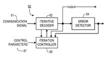
- FIG. 4 illustrates a block diagram of a decoding system according to a representative embodiment of the present invention.
- FIG. 5 is a flow diagram for explaining iteration-control processing, according to a representative embodiment of the present invention, where the transmission format of the received communication signal is known.
- FIG. 6 illustrates a block diagram of a system for calculating an estimate of bit error rate, according to a representative embodiment of the present invention.
- FIG. 7 is a graph illustrating the relationship between bit error rate and undetected error rate for three different CRCs.
- FIG. 4 illustrates a block diagram of a decoding system 80 according to a representative embodiment of the present invention.
- a communication signal 81 is received and input by iterative decoder 82 .
- decoder 82 is identical to turbo decoder 50 , shown in FIG. 3 .
- any other iterative decoder instead may be used, depending upon the expected type of encoding for the received communication signal 81 .
- error detector 84 The output decisions from decoder 82 are provided to error detector 84 .
- the nature of error detector 84 will depend upon the expected type of encoding for received communication signal 81 .
- communication signal 81 includes an embedded error-detection code.
- the error-detection code is a cyclic redundancy check (CRC) code.
- CRC cyclic redundancy check
- error detector 84 performs a CRC check on the decoder decisions for each frame provided by decoder 82 in order to determine whether there appears to be a detected error in such frame.
- frame is used in its generic sense, referring to a data block, segment or packet of a predetermined length.
- decoder 82 provides decisions at every iteration, generally improving the quality of its decisions with each subsequent iteration.
- Iteration controller 85 monitors data from decoder 82 and error detector 84 , determining whether a further iteration is required or whether processing on the present frame can be halted, and controlling iterative decoder 82 accordingly. Additional details regarding the functionality provided by controller 85 are discussed in the more particularized embodiments described below.
- a transmission format is a set of parameters to form the transmitted data, which may include, e.g., coding rate or other encoding parameters, packet data size, modulation format and/or interleaving parameters.
- a frame-decoding operation When a frame-decoding operation according to the present invention is begun, it is provided with data format information (e.g. data packet size, code rate), and inputs information indicating whether such format information is known to be the format in which the data actually were transmitted or is simply a format that has been assumed. If the transmission format is known, the iteration control preferably is executed as described in the section below titled “Known Transmission Format”. Otherwise, iteration control preferably is executed as described in the section below titled “Unknown Transmission Format”.
- data format information e.g. data packet size, code rate
- step 102 controller 85 causes decoder 82 to perform an iteration. Thus, for the initial execution of step 102 this will be the first decoding iteration performed by decoder 82 .
- controller 85 receives one or more decoding parameters for the current iteration from decoder 82 , calculates a function of those parameters, and then determines whether the calculated value P 0 of the function passes a specified threshold test.
- the calculated value P 0 comprises an estimate of bit error rate based on the log likelihood ratio (LLR) magnitudes across all bits in the data packet.
- LLR log likelihood ratio
- the LLR is the final value input into hard-decision module 64 of iterative error-correction decoder 50 , i.e., L(û k ).
- P 0 preferably is calculated as follows:
- a system 110 for calculating P 0 is shown in FIG. 6 .
- Input into the system 110 are the L(û k ) values, which have been output from adder 62 (shown in FIG. 3 ). Initially, the magnitudes denoted as x are taken in element 112 . Then, the function
- the x-axis is the actual bit error rate of the packet data
- the y-axis is the probability of the CRC indicating that the data packet is error-free when in fact there is at least one error
- the subject CRCs have the following generator polynomials:
- the specified maximum undetected error rate preferably is input into system 80 (shown in FIG. 4 ) as one of the control parameters 87 , e.g., by a user or by an automated process, e.g., that varies such parameters on a dynamic basis in an attempt to achieve optimal performance under varying conditions.
- step 103 If the thresholding test of step 103 is satisfied, then processing proceeds to step 105 . Otherwise, processing proceeds to step 107 (discussed below).
- step 105 a determination is made as to whether the embedded CRC code (or other error-detection code) indicates that the data block has been correctly received. If so, then processing is concluded and the iterations of the decoder 82 can be halted. Otherwise, i.e., if an error was detected, processing proceeds to step 107 .
- the embedded CRC code or other error-detection code
- step 107 a determination is made as to whether the maximum number of iterations has occurred. If not, then processing proceeds to step 102 to perform the next iteration. If so, then processing is concluded, with the output message that the data block either was received in error or cannot be determined to be error-free with sufficient confidence.
- the foregoing embodiment of the invention uses a derived relationship between a parameter of the decoder 82 (i.e., the magnitudes of the turbo decoding LLRs in the present case) and the decoding bit error rate in order to estimate the bit error rate the decoder 82 is achieving. Then, by combining this estimate with a derived relationship between CRC error-detection probability and bit error rate, a threshold is established and used to decide whether the decoder 82 is at a stage where the CRC error detection probability is above a specified level.
- the embodiment in the following section uses similar concepts to also simultaneously determine whether a particular transmission format assumption is correct, incorrect, or uncertain.
- the early termination is based on both the P 0 measurement and a CRC check. If P 0 is less than a specified threshold, e.g., such that the CRC undetected error probability is small enough, then a CRC pass will cause an early termination of the turbo decoding. On the other hand, if the P 0 check does not pass, then iteration will continue till the pre-determined maximum iteration number, and the CRC check at the end of the iterations will be delivered to the upper layer, irrespective of whether the P 0 test passes or not.
- the CRC check preferably is initially set to false so that if step 105 is never reached, the false value is delivered to the upper layer.
- an access network can send an access terminal (AT) a packet of data with one out of a few possible transmission formats (packet size, modulation order, etc.).
- the AT needs to decide which one of the possible transmission formats actually was used during transmission by trying to demodulate and decode the received packet with each assumed transmission format.
- This format-determination task can be performed by the turbo decoder.
- the turbo decoder can decode the packet with an assumed transmission format by passing the built-in CRC (cyclic redundancy check), then there is a high likelihood that the assumed format corresponds to the actual transmission format.
- CRC cyclic redundancy check
- CRC alone is not always the most efficient and reliable approach for format determination, because a CRC check has a non-zero error detection probability.
- the turbo decoder it is desirable for the turbo decoder to utilize at least one additional measure when attempting to identify the transmission format.
- FIG. 8 One technique for achieving this, according to a representative embodiment of the present invention, is shown in FIG. 8 .
- the technique illustrated in FIG. 8 can be divided into certain distinct processing sections 160 , 170 and 180 .
- Section 160 attempts to identify when iterations can be halted in a similar manner to the processing described above in connection with FIG. 5 .
- processing section 170 attempts to determine whether the assumed format can be quickly rejected.
- processing section 180 provides a threshold test for confirming the assumed format even if the maximum number of iterations has occurred and the CRC check still has not passed.
- step 161 instructs decoder 82 to perform the first iteration or (for subsequent passes) the next iteration, in the same manner as step 102 (in FIG. 5 ).
- Step 162 calculates a value P 0 and then determines whether it passes a specified threshold test. The same considerations apply to step 162 that applied to step 103 above and, accordingly, step 162 is not described in detail here. If the threshold test of step 162 passes, processing proceeds to step 163 , which corresponds to the CRC check 105 described above, and, therefore, step 163 also is not described in detail here. On the other hand, if the threshold test of step 162 fails, rather than immediately checking for the final iteration (as in the technique of FIG. 5 ), processing transfers to section 170 to determine whether the transmission format assumption can be immediately rejected.
- step 171 P 0 is compared against a threshold Th(rate). If P 0 >Th(rate), then processing immediately proceeds to step 172 , in which the assumed format is deselected and processing is halted with respect to the currently assumed transmission format. The process of FIG. 8 can then be run with a different assumed transmission format. On the other hand, if the assumed format cannot be immediately rejected in step 171 (i.e., P 0 ⁇ Th(rate)), then processing proceeds to step 191 , where processing proceeds either to the next iteration at step 161 or (if at the last iteration) to step 192 .
- the thresholding test of step 171 it is noted that if the transmission format assumption is incorrect, then the resulting data likely will be fairly random, meaning that the threshold Th(rate) can be set to a value that is just below 0.5, e.g., to a value of 0.4 or 0.3.
- step 163 if the CRC check of step 163 passes then the assumed format is selected (i.e., confirmed) in step 183 and the iterations of decoder 82 can be halted with confidence that the data block has been decoded correctly. On the other hand, if the CRC check of step 163 fails, then processing proceeds to step 165 .
- step 165 (which corresponds to step 107 of FIG. 5 ), a determination is made as to whether the current iteration is the final iteration. If not, processing proceeds to step 161 to begin the next iteration. If so, processing proceeds to step 181 in processing section 180 in order to determine whether the assumed format at least can be confirmed (even if the current data block cannot be decoded with sufficient confidence).
- step 181 P 0 is compared against a threshold Th(BER), e.g., a target decoding error rate of 1.9*10 ⁇ 5 . If P 0 ⁇ Th(BER), then processing proceeds to step 183 in which the assumed format is confirmed and processing is halted. On the other hand, if P 0 ⁇ Th(BER) Then processing proceeds to step 192 in which the assumed format is tagged as “uncertain” and processing is halted. It is noted that step 191 is identical to step 165 except that it is not necessary to perform the test of step 181 after step 191 because the test in step 171 already failed.
- Th(BER) e.g., a target decoding error rate of 1.9*10 ⁇ 5 .
- decoder 82 is halted prior to the maximum number of iterations with the conclusion that the data block has been decoded with a sufficient level of confidence and the assumed data transmission format has been confirmed; (ii) decoder 82 is halted because a determination has been made that the transmission format assumption is incorrect, in which case the received data block can be reprocessed using a different transmission format assumption and using the processing of FIG. 8 ; (iii) decoder 82 is halted because the current data block cannot be decoded with adequate confidence, but the transmission format has been confirmed, in which case other received data blocks can be processed using the confirmed transmission format and the technique of FIG.
- a request can be issued to resend the current data block; or (iv) the current data block cannot be decoded with sufficient confidence and the data transmission format can neither be confirmed nor rejected, in which case the current data block can be processed using other possible transmission format assumptions, other received data blocks can be processed using the current or other transmission format assumptions (e.g., using the processing of FIG. 5 or the processing of FIG. 8 ), and a request can be issued to resend the current data block.
- the technique of FIG. 8 uses two additional thresholds, as compared with the technique of FIG. 5 .
- Both of Th(BER) and Th(rate), like the specified maximum undetected error rate, preferably are included in the control parameters 87 that are input into system 80 , e.g., by a user or by another automated process that varies such parameter on a dynamic basis in an attempt to achieve optimal performance under varying conditions.
- Th(CRC) having a value of ⁇ 6*10 ⁇ 4
- Th(rate) having a value of 0.4 or 0.3
- Th(BER) having a value of 1.9*10 ⁇ 5 , is less than Th(CRC).
- turbo code channel from the turbo encoder, through the transmission channel, and ending at the output of the turbo decoder can be viewed as a binary symmetric channel (BSC) with crossover probability P 0 (i.e., the probability that a transmitted bit will be incorrectly identified as its inverse at the receiver).
- BSC binary symmetric channel
- P 0 crossover probability
- An iterative decoding algorithm using a maximum a posteriori (MAP) criterion needs to obtain the following variable from the received vector y:
- the present invention provides improved decoders.
- Some of the characteristics and advantages of certain representative embodiments of the present invention are as follows:
- Such devices typically will include, for example, at least some of the following components interconnected with each other, e.g., via a common bus: one or more central processing units (CPUs); read-only memory (ROM); random access memory (RAM); input/output software and circuitry for interfacing with other devices (e.g., using a hardwired connection, such as a serial port, a parallel port, a USB connection or a firewire connection, or using a wireless protocol, such as Bluetooth or a 802.11 protocol); software and circuitry for connecting to one or more networks (e.g., using a hardwired connection such as an Ethernet card or a wireless protocol, such as code division multiple access (CDMA), global system for mobile communications (GSM), Bluetooth, a 802.11 protocol, or any other cellular-based or non-cellular-based system), which networks, in turn, in many embodiment
- CDMA code division multiple access
- GSM global system for mobile communications
- Bluetooth Bluetooth
- 802.11 protocol any other cellular-based or non-cellular-based system
- the process steps to implement the above methods and functionality typically initially are stored in mass storage (e.g., the hard disk), are downloaded into RAM and then are executed by the CPU out of RAM.
- mass storage e.g., the hard disk
- the process steps initially are stored in RAM or ROM.
- the present invention also relates to machine-readable media on which are stored program instructions for performing the methods and functionality of this invention.
- Such media include, by way of example, magnetic disks, magnetic tape, optically readable media such as CD ROMs and DVD ROMs, or semiconductor memory such as PCMCIA cards, various types of memory cards, USB memory devices, etc.
- the medium may take the form of a portable item such as a miniature disk drive or a small disk, diskette, cassette, cartridge, card, stick etc., or it may take the form of a relatively larger or immobile item such as a hard disk drive, ROM or RAM provided in a computer or other device.
- functionality sometimes is ascribed to a particular module or component. However, functionality generally may be redistributed as desired among any different modules or components, in some cases completely obviating the need for a particular component or module and/or requiring the addition of new components or modules.
- the precise distribution of functionality preferably is made according to known engineering tradeoffs, with reference to the specific embodiment of the invention, as will be understood by those skilled in the art.
Abstract
Description
where K is the number of bits in the data packet.
is performed in
CRC16: p(x)=x 16 +x 12 +x 5+1=(x+1)(x 15 +x 14 x 13 +x 12 +x 4 +x 3 +x 2 +x+1)
CRC24EVDO: p(x)=x 24 +x 23 +x 6 +x 5 +x+1=(x+1)(x 23 +x 5+1)
CRC24J: p(x)=(x+1)(x 23 +x 17 +x 13 +x 12 +x 11 +x 9 +x 8 +x 7 +x 5 +x 3+1)
upon which the MAP algorithm makes the decision as follows:
û k=sign(L(û k |y)).
P(û k=+1|y)=P(u k=+1|y)
P(û k=−1|y)=P(u k=−1|y)
Similarly:
=1−P0
The final result is obtained from the symmetric property of the channel and the decoder. Moreover, because
Eq. (1.3) can be written as:
Advantages and Characteristics of Certain Representative Embodiments
-
- A decoder that is capable of identifying if the data being decoded have been encoded with an assumed parameter.
- A decoder in which the decision regarding whether the assumed transmission format is correct is reached by utilizing the built-in CRC (or other built-in error-detection code), and by averaging a function of the magnitude of certain decoding metrics.
- Using a particular relationship that enables the decoder to determine the error probability based on the magnitude of one or more decoding metrics.
- Using a function of the magnitude of the LLR values (e.g., an average of such function values) to obtain an estimation of decoding error rate, and using this estimation to provide a stop decision, e.g., thereby resulting in a controllable decoding error rate and CRC error detection rate. In addition, when needed, the same decoding error-rate estimation can be used to provide judgment as to whether assumed encoding parameters are correct, incorrect or uncertain.
- A decoder that, at the same time of performing decoding, also can provide judgment as to whether the assumed transmission format is correct, incorrect or uncertain.
- Using a decoding stop criterion that is based on whether the decoder has achieved an error-free decoding with a specified level of accuracy (e.g., rather than being based on whether a further iteration will change LLR distribution), thereby reducing unnecessary iterations.
System Environment.
Claims (21)
Priority Applications (2)
| Application Number | Priority Date | Filing Date | Title |
|---|---|---|---|
| US11/559,441 US8024644B2 (en) | 2006-11-14 | 2006-11-14 | Communication signal decoding |
| CN2007100053761A CN101083513B (en) | 2006-11-14 | 2007-02-14 | Apparatus,method and system of communication signal decoding |
Applications Claiming Priority (1)
| Application Number | Priority Date | Filing Date | Title |
|---|---|---|---|
| US11/559,441 US8024644B2 (en) | 2006-11-14 | 2006-11-14 | Communication signal decoding |
Publications (2)
| Publication Number | Publication Date |
|---|---|
| US20080115031A1 US20080115031A1 (en) | 2008-05-15 |
| US8024644B2 true US8024644B2 (en) | 2011-09-20 |
Family
ID=38912818
Family Applications (1)
| Application Number | Title | Priority Date | Filing Date |
|---|---|---|---|
| US11/559,441 Expired - Fee Related US8024644B2 (en) | 2006-11-14 | 2006-11-14 | Communication signal decoding |
Country Status (2)
| Country | Link |
|---|---|
| US (1) | US8024644B2 (en) |
| CN (1) | CN101083513B (en) |
Cited By (3)
| Publication number | Priority date | Publication date | Assignee | Title |
|---|---|---|---|---|
| US20090132889A1 (en) * | 2007-11-21 | 2009-05-21 | Micron Technology, Inc. | Memory controller supporting rate-compatible punctured codes |
| US20100272011A1 (en) * | 2009-04-27 | 2010-10-28 | Qualcomm Incorporated | Iterative decoding with configurable number of iterations |
| US8468428B1 (en) * | 2007-07-11 | 2013-06-18 | Marvell International Ltd. | Early stopping rules for non-binary turbo codes |
Families Citing this family (6)
| Publication number | Priority date | Publication date | Assignee | Title |
|---|---|---|---|---|
| US7853853B2 (en) * | 2007-10-02 | 2010-12-14 | Intel Corporation | Device, system, and method of multi-level feedback |
| US8086940B2 (en) * | 2008-04-28 | 2011-12-27 | Newport Media, Inc. | Iterative decoding between turbo and RS decoders for improving bit error rate and packet error rate |
| EP2538565A4 (en) * | 2010-02-19 | 2017-08-02 | Furukawa Electric Co., Ltd. | Pulse receiver and burst signal receiving method |
| US9767823B2 (en) * | 2011-02-07 | 2017-09-19 | Qualcomm Incorporated | Devices for encoding and detecting a watermarked signal |
| EP3361658A4 (en) * | 2015-10-28 | 2018-10-31 | Huawei Technologies Co., Ltd. | Data processing method and apparatus |
| US11695431B2 (en) * | 2018-10-24 | 2023-07-04 | Star Ally International Limited | LPWAN communication protocol design with turbo codes |
Citations (20)
| Publication number | Priority date | Publication date | Assignee | Title |
|---|---|---|---|---|
| US5996104A (en) * | 1996-09-13 | 1999-11-30 | Herzberg; Hanan | System for coding system |
| US6161209A (en) * | 1997-03-28 | 2000-12-12 | Her Majesty The Queen In Right Of Canada, As Represented By The Minister Of Industry Through The Communications Research Centre | Joint detector for multiple coded digital signals |
| US20010052104A1 (en) * | 2000-04-20 | 2001-12-13 | Motorola, Inc. | Iteration terminating using quality index criteria of turbo codes |
| US20020122423A1 (en) * | 2000-11-30 | 2002-09-05 | Tathagato Mukhopadhyay | Method to improve performance and reduce complexity of turbo decoder |
| US20020147954A1 (en) * | 2001-03-22 | 2002-10-10 | Shea John M. | Method and coding means for error-correction utilizing concatenated parity and turbo codes |
| US6518892B2 (en) * | 2000-11-06 | 2003-02-11 | Broadcom Corporation | Stopping criteria for iterative decoding |
| US20030084398A1 (en) * | 2001-01-02 | 2003-05-01 | Icomm Technologies Inc. | High speed turbo codes decoder for 3g using pipelined siso log-map decoders architecture |
| US6738948B2 (en) * | 2001-04-09 | 2004-05-18 | Motorola, Inc. | Iteration terminating using quality index criteria of turbo codes |
| US20040199848A1 (en) * | 2002-03-29 | 2004-10-07 | Kazuhiko Tamesue | Error correction decoding apparatus and error correction decoding method |
| US20040234007A1 (en) * | 2002-01-23 | 2004-11-25 | Bae Systems Information And Electronic Systems Integration Inc. | Multiuser detection with targeted error correction coding |
| US6871303B2 (en) * | 1998-12-04 | 2005-03-22 | Qualcomm Incorporated | Random-access multi-directional CDMA2000 turbo code interleaver |
| US6888901B2 (en) * | 2000-12-23 | 2005-05-03 | Samsung Electronics Co., Ltd. | Apparatus and method for stopping iterative decoding in a CDMA mobile communication system |
| US20050111564A1 (en) * | 2003-11-26 | 2005-05-26 | Kramer Gerhard G.T. | Nonsystematic repeat-accumulate codes for encoding and decoding information in a communication system |
| US6996194B2 (en) * | 1999-12-15 | 2006-02-07 | Nokia Mobile Phones, Ltd. | Method and arrangement for iteratively improving a channel estimate |
| US7093180B2 (en) * | 2002-06-28 | 2006-08-15 | Interdigital Technology Corporation | Fast H-ARQ acknowledgement generation method using a stopping rule for turbo decoding |
| US20070113143A1 (en) * | 2005-10-25 | 2007-05-17 | Yu Liao | Iterative decoder with stopping criterion generated from error location polynomial |
| US20070124657A1 (en) * | 2005-11-16 | 2007-05-31 | Nec Electronics Corporation | Decoding device, decoding method, and receiving apparatus |
| US20080115038A1 (en) * | 2006-10-26 | 2008-05-15 | Seagate Technology Llc | Dynamic early termination of iterative decoding for turbo equalization |
| US7415001B2 (en) * | 2002-06-14 | 2008-08-19 | Dspace Pty Ltd | Method and receiver for processing a multi-user signal |
| US7454684B2 (en) * | 2003-04-17 | 2008-11-18 | Icera, Inc. | Apparatus and method for turbo decoder termination |
Family Cites Families (2)
| Publication number | Priority date | Publication date | Assignee | Title |
|---|---|---|---|---|
| KR100321978B1 (en) * | 1998-12-31 | 2002-07-02 | 윤종용 | Apparatus and method for eterative decoding in telecommunication system |
| GB2371952A (en) * | 2001-01-31 | 2002-08-07 | Inmarsat Ltd | Frame synchronisation in a communication system |
-
2006
- 2006-11-14 US US11/559,441 patent/US8024644B2/en not_active Expired - Fee Related
-
2007
- 2007-02-14 CN CN2007100053761A patent/CN101083513B/en not_active Expired - Fee Related
Patent Citations (22)
| Publication number | Priority date | Publication date | Assignee | Title |
|---|---|---|---|---|
| US5996104A (en) * | 1996-09-13 | 1999-11-30 | Herzberg; Hanan | System for coding system |
| US6161209A (en) * | 1997-03-28 | 2000-12-12 | Her Majesty The Queen In Right Of Canada, As Represented By The Minister Of Industry Through The Communications Research Centre | Joint detector for multiple coded digital signals |
| US6871303B2 (en) * | 1998-12-04 | 2005-03-22 | Qualcomm Incorporated | Random-access multi-directional CDMA2000 turbo code interleaver |
| US6996194B2 (en) * | 1999-12-15 | 2006-02-07 | Nokia Mobile Phones, Ltd. | Method and arrangement for iteratively improving a channel estimate |
| US20010052104A1 (en) * | 2000-04-20 | 2001-12-13 | Motorola, Inc. | Iteration terminating using quality index criteria of turbo codes |
| US6518892B2 (en) * | 2000-11-06 | 2003-02-11 | Broadcom Corporation | Stopping criteria for iterative decoding |
| US6686853B2 (en) * | 2000-11-06 | 2004-02-03 | Broadcom Corporation | Method and apparatus for iterative decoding |
| US20020122423A1 (en) * | 2000-11-30 | 2002-09-05 | Tathagato Mukhopadhyay | Method to improve performance and reduce complexity of turbo decoder |
| US6888901B2 (en) * | 2000-12-23 | 2005-05-03 | Samsung Electronics Co., Ltd. | Apparatus and method for stopping iterative decoding in a CDMA mobile communication system |
| US20030084398A1 (en) * | 2001-01-02 | 2003-05-01 | Icomm Technologies Inc. | High speed turbo codes decoder for 3g using pipelined siso log-map decoders architecture |
| US20020147954A1 (en) * | 2001-03-22 | 2002-10-10 | Shea John M. | Method and coding means for error-correction utilizing concatenated parity and turbo codes |
| US6738948B2 (en) * | 2001-04-09 | 2004-05-18 | Motorola, Inc. | Iteration terminating using quality index criteria of turbo codes |
| US20040234007A1 (en) * | 2002-01-23 | 2004-11-25 | Bae Systems Information And Electronic Systems Integration Inc. | Multiuser detection with targeted error correction coding |
| US7092464B2 (en) * | 2002-01-23 | 2006-08-15 | Bae Systems Information And Electronic Systems Integration Inc. | Multiuser detection with targeted error correction coding |
| US20040199848A1 (en) * | 2002-03-29 | 2004-10-07 | Kazuhiko Tamesue | Error correction decoding apparatus and error correction decoding method |
| US7415001B2 (en) * | 2002-06-14 | 2008-08-19 | Dspace Pty Ltd | Method and receiver for processing a multi-user signal |
| US7093180B2 (en) * | 2002-06-28 | 2006-08-15 | Interdigital Technology Corporation | Fast H-ARQ acknowledgement generation method using a stopping rule for turbo decoding |
| US7454684B2 (en) * | 2003-04-17 | 2008-11-18 | Icera, Inc. | Apparatus and method for turbo decoder termination |
| US20050111564A1 (en) * | 2003-11-26 | 2005-05-26 | Kramer Gerhard G.T. | Nonsystematic repeat-accumulate codes for encoding and decoding information in a communication system |
| US20070113143A1 (en) * | 2005-10-25 | 2007-05-17 | Yu Liao | Iterative decoder with stopping criterion generated from error location polynomial |
| US20070124657A1 (en) * | 2005-11-16 | 2007-05-31 | Nec Electronics Corporation | Decoding device, decoding method, and receiving apparatus |
| US20080115038A1 (en) * | 2006-10-26 | 2008-05-15 | Seagate Technology Llc | Dynamic early termination of iterative decoding for turbo equalization |
Non-Patent Citations (4)
| Title |
|---|
| Hagenauer et al. "Iterative Decoding of Binary Block and Convolutional Codes." IEEE Transactions on Information Theory, vol. 42, No. 2, Mar. 1996 pp. 429-445. |
| Shao et al. "Two Simple Stopping Criteria for Turbo Decoding." IEEE Transactions on Communications. vol. 47, No. 8, Aug. 1999 pp. 1117-1120. |
| Wolf et al. "An Exact Evaluation of the Probability of Undetected Error for Certain Shortened Binary CRC Codes." QUALCOMM, Inc. San Diego, CA 92121. 1988 IEEE. pp. 287-292. |
| Zhai et al. "Techniques for Early Stopping and Error Detection in Turbo Decoding." IEEE Transactions on Communications. vol. 51, No. 10, Oct. 2003 pp. 1617-1623. |
Cited By (7)
| Publication number | Priority date | Publication date | Assignee | Title |
|---|---|---|---|---|
| US8468428B1 (en) * | 2007-07-11 | 2013-06-18 | Marvell International Ltd. | Early stopping rules for non-binary turbo codes |
| US20090132889A1 (en) * | 2007-11-21 | 2009-05-21 | Micron Technology, Inc. | Memory controller supporting rate-compatible punctured codes |
| US8327245B2 (en) * | 2007-11-21 | 2012-12-04 | Micron Technology, Inc. | Memory controller supporting rate-compatible punctured codes |
| US8966352B2 (en) | 2007-11-21 | 2015-02-24 | Micron Technology, Inc. | Memory controller supporting rate-compatible punctured codes and supporting block codes |
| US9442796B2 (en) | 2007-11-21 | 2016-09-13 | Micron Technology, Inc. | Memory controller supporting rate-compatible punctured codes |
| US20100272011A1 (en) * | 2009-04-27 | 2010-10-28 | Qualcomm Incorporated | Iterative decoding with configurable number of iterations |
| US8675693B2 (en) * | 2009-04-27 | 2014-03-18 | Qualcomm Incorporated | Iterative decoding with configurable number of iterations |
Also Published As
| Publication number | Publication date |
|---|---|
| CN101083513B (en) | 2012-09-05 |
| US20080115031A1 (en) | 2008-05-15 |
| CN101083513A (en) | 2007-12-05 |
Similar Documents
| Publication | Publication Date | Title |
|---|---|---|
| US8024644B2 (en) | Communication signal decoding | |
| EP3729697B1 (en) | Decoding signals by guessing noise | |
| US5968198A (en) | Decoder utilizing soft information output to minimize error rates | |
| US9397698B1 (en) | Methods and apparatus for error recovery in memory systems employing iterative codes | |
| US5757821A (en) | Method and apparatus for detecting communication signals having unequal error protection | |
| US20090177943A1 (en) | Error correction coding using soft information and interleaving | |
| US6879648B2 (en) | Turbo decoder stopping based on mean and variance of extrinsics | |
| US8127216B2 (en) | Reduced state soft output processing | |
| US7634706B1 (en) | Majority-detected erasure enhanced error correction | |
| US9098411B1 (en) | Methods and apparatus for defect detection and correction via iterative decoding algorithms | |
| US6898254B2 (en) | Turbo decoder stopping criterion improvement | |
| US7480852B2 (en) | Method and system for improving decoding efficiency in wireless receivers | |
| US9256492B1 (en) | Iterative decoding systems using noise-biasing | |
| JP3059133B2 (en) | Bit error rate measurement device using Viterbi decoder | |
| EP1271509A1 (en) | Method and apparatus for detecting and correcting errors in a magnetic recording channel of a mass storage system | |
| US10720944B2 (en) | Convolutional code decoder and convolutional code decoding method | |
| US10826541B2 (en) | Convolutional code decoder and convolutional code decoding method | |
| US11251809B2 (en) | Soft-aided decoding of staircase codes | |
| US20080115038A1 (en) | Dynamic early termination of iterative decoding for turbo equalization | |
| US6915474B2 (en) | Turbo decoding apparatus and decoding iteration count controlling method in turbo decoding | |
| US6192500B1 (en) | Method and apparatus for enhanced performance in a system employing convolutional decoding | |
| EP1387516A1 (en) | Blind transport format detection in spread spectrum receivers | |
| JP2003223764A (en) | Data reproducing device | |
| CN114499548B (en) | Decoding method, device and storage medium | |
| JPH1022839A (en) | Soft discrimination error-correction decoding method |
Legal Events
| Date | Code | Title | Description |
|---|---|---|---|
| AS | Assignment |
Owner name: VIA TELECOM CO., LTD., CAYMAN ISLANDS Free format text: ASSIGNMENT OF ASSIGNORS INTEREST;ASSIGNOR:SHEN, QIANG;REEL/FRAME:018665/0933 Effective date: 20061128 |
|
| STCF | Information on status: patent grant |
Free format text: PATENTED CASE |
|
| FPAY | Fee payment |
Year of fee payment: 4 |
|
| AS | Assignment |
Owner name: INTEL CORPORATION, CALIFORNIA Free format text: ASSIGNMENT OF ASSIGNORS INTEREST;ASSIGNOR:VIA TELECOM CO., LTD.;REEL/FRAME:037096/0075 Effective date: 20151020 |
|
| FEPP | Fee payment procedure |
Free format text: PAYOR NUMBER ASSIGNED (ORIGINAL EVENT CODE: ASPN); ENTITY STATUS OF PATENT OWNER: LARGE ENTITY |
|
| FEPP | Fee payment procedure |
Free format text: MAINTENANCE FEE REMINDER MAILED (ORIGINAL EVENT CODE: REM.); ENTITY STATUS OF PATENT OWNER: LARGE ENTITY |
|
| LAPS | Lapse for failure to pay maintenance fees |
Free format text: PATENT EXPIRED FOR FAILURE TO PAY MAINTENANCE FEES (ORIGINAL EVENT CODE: EXP.); ENTITY STATUS OF PATENT OWNER: LARGE ENTITY |
|
| STCH | Information on status: patent discontinuation |
Free format text: PATENT EXPIRED DUE TO NONPAYMENT OF MAINTENANCE FEES UNDER 37 CFR 1.362 |
|
| FP | Lapsed due to failure to pay maintenance fee |
Effective date: 20190920 |