US8023744B2 - Pattern matching system and targeted object pursuit system using light quantities in designated areas of images to be compared - Google Patents
Pattern matching system and targeted object pursuit system using light quantities in designated areas of images to be compared Download PDFInfo
- Publication number
- US8023744B2 US8023744B2 US11/686,561 US68656107A US8023744B2 US 8023744 B2 US8023744 B2 US 8023744B2 US 68656107 A US68656107 A US 68656107A US 8023744 B2 US8023744 B2 US 8023744B2
- Authority
- US
- United States
- Prior art keywords
- data
- block
- area
- image
- pattern
- Prior art date
- Legal status (The legal status is an assumption and is not a legal conclusion. Google has not performed a legal analysis and makes no representation as to the accuracy of the status listed.)
- Expired - Fee Related, expires
Links
Images


Classifications
-
- G—PHYSICS
- G06—COMPUTING; CALCULATING OR COUNTING
- G06T—IMAGE DATA PROCESSING OR GENERATION, IN GENERAL
- G06T7/00—Image analysis
- G06T7/20—Analysis of motion
- G06T7/223—Analysis of motion using block-matching
Definitions
- the present invention relates to a pattern matching system that determines whether or not a plurality of images matches each other, and a targeted object pursuit system that pursues the movement of a specified targeted object within a plurality of images captured sequentially using the above pattern matching system.
- a pattern matching system that calculates the likeness between a plurality of images is known.
- the pattern matching is used for pursuit of a targeted object moving within a plurality of images captured sequentially.
- the likeness is calculated by the following operation. First, the captured image is divided into smaller image components and the luminance of the divided image components is detected. Second, the luminance level of each image component into which a first image is divided is compared to that of a corresponding image component, into which a second image of the same location but subsequent to the first image, is divided. Finally, a value based on the number of image components of which the luminance levels from the first and second images are in agreement with each other is calculated as the likeness between the first and second images.
- the greater the number of image components that are compared the greater the accuracy of the calculated likeness value suggesting whether or not the first and second images are in agreement with each other.
- the greater the number of compared image components also increases the size requirement, in bits, of the digital arithmetical unit necessary for the pattern matching system.
- the capacity of the digital arithmetical unit is not always used completely.
- an object of the present invention is to provide a pattern matching system that uses a digital arithmetical unit effectively, and a targeted object pursuit system that makes use of the pattern matching system.
- a pattern matching system that outputs a likeness value, comprising a designation block, a comparison block, a calculation block, and an output block.
- the likeness value shows how much a first and second image compares to each other.
- the designation block designates first and second image data corresponding to said first and second images, respectively, as data to be compared.
- the first and second image data is digital data.
- the first and second image data comprises 2 ⁇ x (x is a natural number) of area data. Data level of the area data varies according to the intensity of light incident to a pattern area.
- the first and second images comprises 2 ⁇ x of the pattern areas.
- the comparison block compares data levels of the area data corresponding to the pattern areas at the relatively same location in the first and second images.
- the calculation block calculates the likeness value.
- the likeness value varies according to the number of the pattern areas where the absolute value of the difference between the compared data levels of the area data of the first and second images is less than a predetermined standard value.
- the output block outputs the likeness value.
- said pattern area is broadened when the intensity of light of the entire first or second image is lower than a first threshold value.
- a targeted object pursuit system that pursues the movement of a targeted object within a plurality of sequentially captured images.
- the targeted object pursuit system comprises a first setting block, a second setting block, a recognition block, a data generator, a comparison block, a calculation block, a determination block, and a re-designation block.
- the first setting block initially designates a partial area located at a predetermined location in the captured image as a pursuit area for pursuing the targeted object.
- the second setting block designates areas displaced from the pursuit area in a first and second direction as a first and second candidate area, respectively.
- the recognition block extracts a standard image from the captured image captured at a first timing.
- the recognition block extracts a first and second candidate image from the captured image at a second timing which is subsequent to the first timing.
- the standard image corresponds to the pursuit area.
- the first and second candidate images correspond to the first and second candidate area, respectively.
- the data generator generates area data of which the data level varies according to the intensity of light incident to a pattern area.
- the standard image, and the first and second images comprises 2 ⁇ x (x is a natural number) of the pattern areas.
- the comparison block compares the data level of the area data corresponding to the pattern areas at the relatively same location in the standard image and one of either the first or second images.
- the calculation block calculates the likeness value.
- the likeness value varies according to the number of the pattern areas where the absolute value of the difference between the compared data levels of the area data is less than a predetermined standard value.
- the determination block determines which direction the targeted object moves during a period between the first and second timing to be either the first or second direction based on the difference between the likeness value of the standard image and the first candidate image and the likeness value of the standard image and the second candidate image.
- the re-designation block re-designates a candidate area corresponding to the determined direction where the targeted object moved as the new pursuit area.
- FIG. 1 is a block diagram showing the internal structure of a digital camera having a targeted object pursuit system using a pattern matching system of an embodiment of the present invention
- FIG. 2 is a block diagram showing the internal structure of the DSP
- FIG. 3 is a block diagram showing the internal structure of the pursuit block
- FIG. 4 shows the structure of the small pixel block
- FIG. 5 shows the structure of the large pixel block
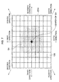
- FIG. 6 shows the light-receiving surface, comprising small pixel blocks, for explaining the form of the scanning area
- FIG. 7 shows the light-receiving surface, comprising large pixel blocks, for explaining the form of the scanning area
- FIG. 8 shows a location of the CA 1 relative to the SA
- FIG. 9 shows a location of the CA 2 relative to the SA
- FIG. 10 shows a location of the CA 3 relative to the SA
- FIG. 11 shows a location of the CA 4 relative to the SA
- FIG. 12 shows a location of the CA 5 relative to the SA
- FIG. 13 shows a location of the CA 6 relative to the SA
- FIG. 14 shows a location of the CA 7 relative to the SA
- FIG. 15 shows a location of the CA 8 relative to the SA
- FIG. 16 shows an example of the luminance value of the small pixel blocks included in the SA
- FIG. 17 shows binary luminance values of the small pixel blocks described in FIG. 16 ;
- FIG. 18 shows an example of the binary luminance values of the small pixel blocks included in the CA 1 ;
- FIG. 19 is a first flowchart explaining the first part of the process for designation of the scanning area carried out by the pursuit block.
- FIG. 20 is a second flowchart explaining the remaining part of the process for designation of the scanning area carried out by the pursuit block.
- a digital camera 10 comprises a photographic optical system 11 , an imaging device 12 , an analog front end (AFE) 13 , a DSP 14 , an input block 15 , a zooming-driver 16 , a focusing-driver 17 , and other components.
- AFE analog front end
- the photographic optical system 11 is optically connected to the imaging device 12 .
- An optical image of an object through the photographic optical system 11 is incident to the light-receiving surface of the imaging device 12 .
- the imaging device 12 is, for example, a CCD area sensor. When the imaging device 12 captures the optical image of the object upon its light-receiving surface, the imaging device 12 generates an image signal corresponding to the captured optical image.
- the photographic optical system 11 comprises plural lenses, including a zoom lens 11 a and a focus lens 11 b .
- the zoom lens 11 a and the focus lens 11 b are movable along an optical axis of the photographic optical system 11 .
- the zoom lens 11 a and the focus lens 11 b form a zoom optical system.
- the focal length of the photographic optical system 11 is adjusted by moving the zoom lens 11 a and the focus lens 11 b in relationship to each other. Further, an optical image of an object can be focused on the light-receiving surface of the imaging device 12 by moving the focus lens 11 b.
- the zoom lens 11 a and the focus lens 11 b can be manually moved along the optical axis by a user.
- the zoom lens 11 a and the focus lens 11 b can also be moved by the zooming-driver 16 .
- the focus lens 11 b can also be moved by the focusing-driver 17 so that the object is brought into focus.
- the focus adjustment for the movements of the focus lens 11 b by the focusing-driver 17 is automatically carried out when an auto focus function, as described later, is commenced.
- a diaphragm 18 and a shutter 19 are mounted between the photographic optical system 11 and the imaging device 12 .
- the intensity of light made incident on the light-receiving surface of the imaging device 12 can be varied by adjusting the aperture ratio of the diaphragm 18 .
- An optical image reaches the light-receiving surface by opening the shutter 19 , and an optical image is shielded from the light-receiving surface by closing the shutter 19 .
- a diaphragm-driver 20 drives the diaphragm 18 so that the aperture ratio can be adjusted.
- a shutter-driver 21 drives the shutter 19 so that the shutter can be opened and closed.
- the zooming-driver 16 , the focusing-driver 17 , the diaphragm-driver 20 , and the shutter-driver 21 are all connected to the DSP 14 .
- the DSP 14 controls the operations of the zooming-driver 16 , the focusing-driver 17 , the diaphragm-driver 20 , and the shutter-driver 21 .
- the imaging device 12 is electrically connected to the DSP 14 via the AFE 13 .
- a clock signal is sent from the DSP 14 to the AFE 13 , which generates a frame signal and an imaging device driving signal based on the received clock signal.
- the imaging device driving signal is sent to the imaging device 12 .
- the imaging device 12 is driven based on the imaging device driving signal to generate an image signal that is synchronized with the frame signal.
- pixels are arranged in a matrix on the light-receiving surface of the imaging device 12 .
- a pixel is each unit of area into which an effective receiving area, hereinafter referred to as an ERA, of the light-receiving surface is equally divided into n1 rows and n2 columns.
- Each pixel generates a pixel signal according to the intensity of light incident to the pixel.
- An image signal comprises a plurality of pixel signals generated by a plurality of pixels in the ERA.
- the generated image signal is sent to the AFE 13 , which carries out correlated double sampling and gain adjustment on the image signal.
- the image signal is converted to image data, which is digital data that is sent to the DSP 14 .
- the DSP 14 is connected to a dynamic random access memory (DRAM) 22 , which is used as a work memory for signal processing carried out by the DSP 14 .
- DRAM dynamic random access memory
- the image data received by the DSP 14 is temporarily stored in the DRAM 22 .
- the DSP 14 carries out predetermined signal processing on the image data stored in the DRAM 22 .
- the DSP 14 is connected to a monitor 23 .
- the image data having undergone predetermined signal processing, is sent to the monitor 23 , which is able to display an image corresponding to the received image data.
- the DSP 14 is connected to a card-interface 24 which can be connected to a memory card (not depicted).
- a release operation as described later, is carried out, the image data, having undergone predetermined signal processing, is stored in the memory card.
- the DSP 14 is connected to the input block 15 , where a user inputs operational commands.
- the input block 15 comprises a release button (not depicted), a multi-functional cross-key (not depicted), a power button (not depicted), and other buttons.
- the DSP 14 orders each component of the digital camera 10 to carry out a necessary operation according to a user's command input to the input block 15 .
- a first switch (not depicted) is switched on, and exposure adjustment and focus adjustment are then carried out.
- the intensity of light incident to the ERA is determined based on the image data.
- the intensity of light incident to either the entire ERA or a partial area of the ERA can be determined.
- a weighted exposure adjustment can be carried out by weighting the intensity of light incident to a partial area of the ERA and carrying out the exposure adjustment based on the average intensity of light incident to the adjacent areas surrounding the partial area.
- the position of the focus lens 11 b is adjusted so that an optical image of the desired object can be focused on the light-receiving surface.
- a second switch (not depicted) is switched on. Then, the shutter 19 is driven so as to open and close, and the imaging device 12 is driven so as to capture a static optical image.
- the DSP 14 comprises a first data processing block 14 p 1 , a second data processing block 14 p 2 , a pursuit block 30 , an AF adjustment block 14 a , and a control block 14 c.
- the image data sent from the AFE 13 is input to the first data process block 14 p 1 , which stores the received image data in the DRAM 22 .
- the first data process block 14 p carries out predetermined data processing, such as color interpolation processing, white balance processing, and luminance data generation processing on the stored image data.
- the first data process block 14 p 1 then sends the image data, after having undergone predetermined data processing, to the second data processing block 14 p 2 .
- the second data processing block 14 p 2 carries out predetermined data processing, such as cramp processing and blanking processing, on the received image data. Afterwards, the second data process block 14 p 2 sends the image data to the monitor 23 or the memory card via the card-interface 24 .
- predetermined data processing such as cramp processing and blanking processing
- the first data processing block 14 p 1 also sends the image data to the pursuit block 30 and the AF adjustment block 14 a . Based on the received image data, the pursuit block 30 and the AF adjustment block 14 a determine, in cooperation with each other the position of the focus lens 11 b so that a desired object is brought into focus on the light-receiving surface of the imaging device 12 .
- the pursuit block 30 designates one partial area of the entire captured image as a scanning area, hereinafter referred to as SA.
- the SA is used for capturing an optical image of an object that is desired to be in focus on the light-receiving surface. If the targeted object, which is an object desired to be in focus, moves within the captured image, the pursuit block 30 pursues the targeted object by sequentially re-designating a new partial area where the targeted object has moved, effectively updating the SA.
- the AF adjustment block 14 a determines the position of the focus lens 11 b so that an optical image captured by the SA is in focus. Incidentally, the position of the focus lens 11 b is determined according to the contrast detection method.
- the digital camera 10 has both normal auto focus and pursuit auto focus functions.
- the normal auto focus function By carrying out the normal auto focus function, an object that is located in a fixed partial area of the entire captured image is brought into focus.
- the pursuit auto focus function By carrying out the pursuit auto focus function, an object that moves within the entire captured image is brought into focus. Either the normal auto focus function or the pursuit auto focus function is selected by an operational command to the input block 15 .
- An input signal according to an operational command input to the input block 15 is sent from the input block 15 to the control block 14 c , which controls the first data processing block 14 p 1 , the second data processing block 14 p 2 , the pursuit block 30 , the AF-adjustment block 14 a , and each component of the digital camera 10 according to the received input signal.
- control block 14 c controls both the diaphragm driver 20 to drive the diaphragm 18 and the shutter driver 21 to open and close the shutter 19 .
- control block 14 c controls the focusing-driver 17 to re-position the focus lens 11 b in the focus adjustment.
- the control block 14 c receives lens position data corresponding to the position of the focus lens determined by the AF-adjustment block 14 a .
- the control block 14 c controls the focusing-driver 17 based on the received lens position data.
- the pursuit block 30 comprises a luminance calculation block 31 , a first setting block 32 , a second setting block 33 , a recognition block 34 , and a third setting block 35 .
- each component is controlled by the control block 14 c.
- Luminance data for pixels within the ERA is sent from the first data processing block 14 p 1 to the luminance calculation block 31 when the pursuit auto focus function is carried out.
- the luminance calculation block 31 calculates the luminance of either a small pixel block or a large pixel block based on the received luminance data, for the purpose of minimizing the time of pursuit.
- the small pixel block 12 b is unit of area representing 1/400 of the ERA, which has been equally partitioned into twenty rows and twenty columns.
- the small pixel block 12 b is equally partitioned itself, so that the small pixel block 12 b comprises one hundred pixels arranged in a matrix of ten rows by ten columns.
- the luminance of the small pixel block 12 b is calculated by averaging the luminance of the 100 pixels included in the small pixel block 12 b .
- Data corresponding to the calculated luminance of the small pixel block 12 b is sent to the recognition block 34 .
- the large pixel block 12 B is a unit of area representing one hundredth of the ERA, which has been equally partitioned into ten rows and ten columns.
- the large pixel block 12 B comprises four hundred pixels arranged in a matrix of twenty rows by twenty columns.
- the luminance of the large pixel block 12 B is calculated by averaging the luminance of the 400 pixels included in the large pixel block 12 B. Data corresponding to the calculated luminance of the large pixel block 12 B is sent to the recognition block 34 .
- the light intensity incident to the small pixel block 12 b or the large pixel block 12 B is the same that is used for the intensity detected in the partial area of the ERA for the exposure adjustment.
- the intensity of light incident to the small pixel block 12 b or the large pixel block 12 B is detected for a spot photometry measurement or a spot emphasized photometry measurement.
- the first setting block 32 determines the location of the initial SA so that the center of both the ERA of the imaging device 12 and the initial SA agree with each other. In addition, the first setting block 32 determines the size of the SA based on the luminance of the entire ERA. The initial SA is designated once the location and size of the initial SA has been determined.
- the first setting block 32 receives the data corresponding to the luminance of the entire ERA from the first data processing block 14 p 1 .
- the size of the SA is determined to be the total size of thirty two small pixel blocks 12 b , with 32 being the fifth power of two.
- the shape of the SA is determined to be a form created by removing the four corner blocks from a rectangle comprising small pixel blocks 12 b of six columns across by six rows down, as shown in FIG. 6 .
- the size of the SA is determined to the total size of thirty two large pixel blocks 12 B, with 32 being the fifth power of two.
- the shape of the SA is determined to be a form created by removing the four corner blocks from a rectangle comprising large pixel blocks 12 B of six columns across by rows down, as shown in FIG. 7 .
- the large pixel block 12 B on the ERA are separated from each other by borderlines formed by a plurality of vertical and horizontal lines demarcating the columns and rows created from partitioning the ERA.
- borderlines formed by a plurality of vertical and horizontal lines also separate the small pixel blocks 12 b from each other.
- One of the many intersection points formed by the crosshairs of intersecting vertical and horizontal borderlines can be decided upon as the center of the SA, and the location of the initial SA id designated from the location of the center of the SA. The location of the SA is designated based on the operational command which is input to the input block 15 .
- the second setting block 33 designates eight candidate areas which are of the same size as the current SA, but whose locations are different and determined by displacing the current SA by the same magnitude, but in eight directions.
- the first ⁇ eighth directions are predetermined as the eight directions in which to displace the SA to designate the candidate areas.
- the upper, upper left, left, lower left, lower, lower right, right, and upper right directions are predetermined as the first, second, third, fourth, fifth, sixth, seventh, and eighth directions, respectively, as shown in FIGS. 6 , 7 .
- the magnitude of the displacement from the SA in the first ⁇ eighth directions is determined according to the focal length.
- each location of eight candidate areas in the case where the SA is comprised of thirty two small pixel blocks 12 b is explained below.
- each location of eight candidate areas in the case where the SA is comprised of thirty two large pixel blocks 12 B are determined similar to the method for small pixel blocks 12 b described below.
- a candidate area displaced through one small pixel block 12 b from the SA in the first direction is designated to be the first candidate area, hereinafter referred to as CA 1 , shown in FIG. 8 .
- a candidate area displaced through one small pixel block 12 b from the SA in the second direction is designated to be the second candidate area, hereinafter referred to as CA 2 , shown in FIG. 9 .
- a candidate area displaced through one small pixel block 12 b from the SA in the third direction is designated to be the third candidate area, hereinafter referred to as CA 3 , shown in FIG. 10 .
- a candidate area displaced through one small pixel block 12 b from the SA in the fourth direction is designated to be the fourth candidate area, hereinafter referred to as CA 4 , shown in FIG. 11 .
- a candidate area displaced through one small pixel block 12 b from the SA in the fifth direction is designated to be the fifth candidate area, hereinafter referred to as CA 5 , shown in FIG. 12 .
- a candidate area displaced through one small pixel block 12 b from the SA in the sixth direction is designated to be the sixth candidate area, hereinafter referred to as CA 6 , shown in FIG. 13 .
- a candidate area displaced through one small pixel block 12 b from the SA in the seventh direction is designated to be the seventh candidate area, hereinafter referred to as CA 7 , shown in FIG. 14 .
- a candidate area displaced through one small pixel block 12 b from the SA in the eighth direction is designated to be the eighth candidate area, hereinafter referred to as CA 8 , shown in FIG. 15 .
- the number of the small pixel blocks 12 b or large pixel blocks 12 B corresponding to the magnitude of displacement is determined to be 2, 3, 4, . . . .
- the CA 1 ⁇ CA 8 are designated as the locations to which the SA is displaced in the first ⁇ eighth directions, respectively.
- Data corresponding to the designated CA 1 ⁇ CA 8 is sent to the recognition block 34 .
- data corresponding to the SA initially designated by the first setting block 32 is also sent to the recognition block 34 .
- the image data is sent to the recognition block 34 from the AFE 13 .
- the recognition block 34 extracts image data components corresponding to the SA and the CA 1 ⁇ CA 8 from one frame of image data.
- the image data component corresponds to luminance value for a group of the small pixel blocks 12 b or the large pixel blocks 12 B, comprising the SA or the CA 1 ⁇ CA 8 .
- the image data sent at a first timing contains 120, 30, 60, 55, 70, 110, 100, 70, 40, 105, 40, 85, 95, 65, 25, 40, 150, 120, 60, 30, 25, 45, 100, 120, 110, 95, 80, 50, 90, 75, 80, and 20, from left to right and from top to bottom (see FIG. 16 )
- these luminance values are extracted as the image data component corresponding to the SA at the first timing.
- the SA is comprised of thirty two large pixel blocks 12 B
- the luminance values for large pixel blocks 12 B is extracted as the image data component corresponding to the SA, similar to the method for small pixel blocks 12 b described above.
- the luminance values for the small pixel blocks 12 b of the SA or the CA 1 ⁇ CA 8 are converted to binary values, for example 0 or 1, based on the extracted image data components.
- an average of the luminance values for the small pixel blocks 12 b of the SA or the CA 1 ⁇ CA 8 is calculated, and each individual luminance value is subsequently compared to the average luminance value. If a luminance value is higher than the average luminance value, the luminance value is converted to 1. If a luminance value is lower than the average luminance value, the luminance value is converted to 0.
- the average of the luminance values in the SA shown in FIG. 16 is 73.75.
- the luminance value for the small pixel blocks 12 b of the SA are converted to 1, 0, 0, 0, 0, 1, 1, 0, 0, 1, 0, 1, 1, 0, 0, 0, 1, 1, 1, 0, 0, 1, 1, 1, 1, 1, 1, 1, 1, and 0 from left to right and from top to bottom, respectively (see FIG. 17 ).
- the SA is comprised of thirty two large pixel blocks 12 B
- the luminance values for the large pixel blocks 12 B are converted to binary values, similar to the method for small pixel blocks 12 b described above.
- Data corresponding to the binary luminance values of the small pixel blocks 12 b is sent to the third setting block 35 , which infers to which of the CA 1 ⁇ CA 8 the target object, which is captured by the SA at the current timing, is moved to at the subsequent image capturing timing.
- the inference is carried out based on the binary luminance values of the small pixel blocks 12 b of the SA at one timing and the binary luminance values of the small pixel blocks 12 b of the CA 1 ⁇ CA 8 at a subsequent timing.
- One candidate area is selected from the CA 1 ⁇ CA 8 based on a first ⁇ eighth likeness value, as described below.
- the first ⁇ eighth likeness values are calculated values that indicate how similar the image captured on the SA is to the images captured on the CA 1 ⁇ CA 8 at the subsequent image capturing timing.
- the likeness value is the number of combinations of compared binary luminance values that are unequal. Accordingly, the lower the likeness value, the greater the similarity inferred between the SA and the candidate area.
- the third setting block 35 comprises an exclusive-or circuit (not depicted).
- the binary luminance values of the small pixel blocks 12 b at the relatively same location of the SA and the CA 1 are input to the exclusive-or circuit.
- the exclusive-or circuit outputs 0.
- the exclusive-or circuit outputs 1.
- the binary luminance values for the small pixel blocks 12 b in the CA 1 are 0, 0, 0, 1, 1, 1, 1, 1, 1, 0, 0, 1, 1, 1, 0, 0, 1, 1, 0, 0, 1, 1, 0, 0, 1, 1, and 0 from left to right and from top to bottom, respectively, as shown in FIG. 18 .
- the exclusive-or circuit When the binary luminance values for the small pixel block 12 b of the SA and the CA 1 in the top row and leftmost column are input to the exclusive-or circuit, the exclusive-or circuit outputs 1.
- the exclusive-or circuit outputs 0.
- the exclusive-or circuit when the combinations of the luminance values of the small pixel block 12 b of the SA and the CA 1 at the relatively same location is input to the exclusive-or circuit from left to right and from top to bottom, the exclusive-or circuit outputs 0, 1, 1, 0, 0, 1, 0, 1, 1, 0, 0, 0, 1, 0, 1, 0, 0, 0, 1, 0, 0, and 0, respectively.
- the number of times the exclusive-or circuit outputs 1 is counted and saved as a first likeness value, hereinafter referred to as U(exor).
- the SA and the CA 2 are compared to each other, and the second likeness value, hereinafter referred to as UL(exor), is calculated.
- the SA and the CA 3 are compared to each other, and the third likeness value, hereinafter referred to as L(exor), is calculated.
- the SA and the CA 4 are compared to each other, and the fourth likeness value, hereinafter referred to as DL(exor), is calculated.
- the SA and the CA 5 are compared to each other, and the fifth likeness value, hereinafter referred to as D(exor), is calculated.
- the SA and the CA 6 are compared to each other, and the sixth likeness value, hereinafter referred to as DR(exor), is calculated.
- the SA and the CA 7 are compared to each other, and the seventh likeness value, hereinafter referred to as R(exor), is calculated.
- the SA and the CA 8 are compared to each other, and the eighth likeness value, hereinafter referred to as UR(exor), is calculated.
- the third setting block 35 determines the lowest likeness value among U(exor), UL(exor), L(exor), DL(exor), D(exor), DR(exor), R(exor), and UR(exor).
- the candidate area of which likeness value is the lowest is determined and selected by the third setting block 35 as the area where the target object has moved from the scanning area.
- the selected candidate area is re-designated as a new scanning area.
- Data corresponding to the SA initially designated by the first setting block 32 is sent to the AF adjustment block 23 a through the recognition block 34 and the third setting block 35 .
- the initially designated SA remains the SA, dissimilar to the pursuit auto focus function.
- the process for designation of the scanning area starts when the release button is depressed halfway effectively switching on the pursuit auto focus function. Incidentally, the process for designation of the scanning area is repeated until the power button is switched off or the pursuit auto focus function is switched off.
- an initial location of the SA is designated.
- the center of the initial location is one point designated according to a user's command input.
- step S 101 subsequent to step S 100 , one frame of image data is received and then the process proceeds to step S 102 .
- the photometry measurement is carried out.
- data corresponding to the intensity of light incident to each pixel 12 p is sent from the first data processing block 14 p 1 to the first setting block 32 .
- the first setting block 32 calculate a luminance value for the entire ERA based on the intensity of light incident to each pixel 12 p in one frame of image data.
- step S 103 the luminance value calculated at step S 102 is compared to the first threshold value.
- step S 104 When the luminance value calculated at step S 102 is higher than the first threshold value, the process proceeds to step S 104 , where a pixel block flag is designated to be 0. When the luminance value calculated at step S 102 is lower than the first threshold value, the process proceeds to step S 105 , where the pixel block flag is designated to be 1.
- step S 104 or step S 105 the process proceeds to step S 106 , where the SA corresponding to the location designated at step S 100 and the pixel block flag designated at either step S 104 or step S 105 are designated.
- step S 107 the focal length of the photographic optical system 11 is detected.
- the zooming-driver 16 detects a zoom step corresponding to the relative location of the zoom lens 11 a and the focus lens 11 b .
- Data corresponding to the detected zoom step is sent to the second setting block 33 through the control block 14 c .
- the second setting block 33 determines the focal length corresponding to the zoom step.
- step S 108 the magnitude of displacement from the SA to a candidate area is determined according to the detected focal length.
- the CA 1 ⁇ CA 8 are designated according to the determined magnitude of displacement and the pixel block flag designated at step S 104 or S 105 .
- step S 109 it is determined whether the pixel block flag is either 1 or 0.
- step S 110 the process proceeds to step S 110 , where the luminance value of the small pixel blocks 12 b in the SA are converted to binary values.
- step S 111 the luminance value of the large small pixel blocks 12 B in the SA are converted to binary values.
- step S 110 or S 111 the process proceeds to step S 112 , where a subsequently generated frame of image data is received.
- step S 113 it is determined whether the pixel block flag is either 1 or 0.
- step S 114 the process proceeds to step S 114 , where the luminance values of the small pixel blocks 12 b in the CA 1 ⁇ CA 8 are converted to binary values.
- step S 115 the luminance values of the large pixel blocks 12 B in the CA 1 ⁇ CA 8 are converted to binary values.
- step S 114 or S 115 the process proceeds to step S 116 , where the U(exor), UL(exor), L(exor), DL(exor), D(exor), DR(exor), R(exor), and UR(exor) are calculated based on the binary luminance values in the SA and the CA 1 ⁇ CA 8 .
- step S 117 it is determined which likeness value is the lowest among the U(exor), UL(exor), L(exor), DL(exor), D(exor), DR(exor), R(exor), and UR(exor).
- the candidate area, of which the likeness value is the lowest, is designated new SA.
- the process returns to step S 102 and steps S 102 ⁇ 117 are repeated.
- steps S 117 and S 102 ⁇ S 106 the SA is updated.
- a digital arithmetical unit is effectively used with the pattern matching system.
- the maximum number of bits which a digital arithmetical unit can process is 2 ⁇ x (where x is a natural number).
- the number of data required for detection of the likeness value is thirty two bits, which is 2 ⁇ 5 as described above. Accordingly, the capacity of the digital arithmetical unit can be used completely because the maximum number of bits which a digital arithmetical unit can process is in agreement with the number of data required for the detection.
- the system of the above embodiment is able to carry out the pattern matching more consistently because the luminance values of each pixel block 12 b , 12 B are converted to binary values.
- a portion of the calculated likeness value may not compare to the actual optical image.
- the pattern matching is carried out with greater consistency because the influence of such flicker is reduced as a result of the conversion to binary values.
- the size of the pixel block used for the pattern matching process is changed according to the intensity of light incident to the entire ERA.
- the ability to change the size of the pixel block mitigates the potential for error, caused by noise, in the pattern matching process. This can be explained by the fact that when the intensity of light incident to the entire ERA is generally low, the S/N ratio is also low.
- the number of pixels used for calculating a luminance value of a pixel block increases as the size of the pixel block is enlarged, whereas the noise level does not increase. In this regard, the influence of noise from each pixel signal is neutralized throughout the entire pixel block.
- the capacity exists to increase the accuracy of the pursuit of the targeted object by changing the magnitude of displacement of the CA 1 ⁇ CA 8 from the SA according to the focal length of the photographic optical system 11 , because the speed of movement of an object on the image receiving surface increases as the designated focal length is increased.
- the luminance value of the small or large pixel block 12 b , 12 B is also used for the detected light intensity of required for the spot photometry measurement or the spot emphasized photometry measurement. Accordingly, the processing time is reduced in comparison to when the processing for detecting the intensity of light and for detecting the luminance value of the pixel block 12 b , 12 B are carried out separately.
- the number of the small or large pixel blocks 12 b , 12 B comprising the SA or the candidate area is equal to the fifth power of two in the above embodiment. However, the number may be determined to be the nth power of two, provided that it is equal to the bit number of a digital arithmetical unit used for the pattern matching system.
- the direction in which the targeted object is moved is determined to be one of eight directions in the above embodiment. However, the direction can be determined to be one of a plurality of directions.
- One small pixel block 12 b or one large pixel block 12 B corresponds to the magnitude of displacement from the SA to the CA 1 ⁇ CA 8 when the focal length is adjusted to its minimum value by positioning the zoom lens 11 b at the wide-angle end of the above embodiment.
- any number of small pixel blocks 12 b or large pixel blocks 12 B can correspond to the magnitude of displacement.
- the same effect as that of this embodiment can be achieved as long as the magnitude of displacement is adjusted so that the distance increases with increasing the focal length.
- the SA and the CA 1 ⁇ CA 8 form the shape of a cross in the above embodiment, however, any shapes are adaptable.
- the luminance values of the small or large pixel blocks 12 b , 12 B comprising the SA or the CA 1 ⁇ CA 8 are converted to binary values in the above embodiment.
- the luminance values can be converted to any number of different levels, or, such conversions may not be carried out at all.
- the effect as described above is achieved by carrying out the conversion into binary values, or into values of a level that is different from that of binary values.
- the exclusive-or circuit outputs 0 when the binary luminance values of the small pixel blocks 12 b at the relatively same location of the SA and the CA 1 are equal to each other, in the above embodiment.
- an arithmetical circuit mounted in the third setting block 35 may output 0 when the absolute value of the difference of the converted or non-converted luminance values of the pixel blocks at the relatively same location of the SA and the CA 1 ⁇ CA 8 is lower than a predetermined standard value.
- the number of pixel blocks outputting 1 by the arithmetical circuit may be counted as the likeness value.
- the predetermined standard value is 0 in the above embodiment.
- the size of the pixel block used for the pattern matching process is selected from two different sizes according to the brightness of the entire ERA, in the above embodiment.
- the size of the pixel block used in the pattern matching process can be selected from any number of sizes, or can even be fixed, neither of which would diminish the effectiveness of using the digital arithmetical unit.
- the same effect described above can be achieved by changing the size according to the brightness.
- the size of the pixel block used for the pattern matching process is selected from two different sizes according to the brightness of the entire ERA, in the above embodiment. However, the size is selected according to the brightness of only a part of the ERA.
- the magnitude of displacement from the SA to the CA 1 ⁇ CA 8 is changed according to the focal length of the photographic optical system 11 , in the above embodiment.
- the digital arithmetical unit can be used effectively achieved even if the magnitude of displacement is not changed.
- the same effect described above can be achieved by changing the magnitude of displacement according to the focal length.
- the pixel block 12 b , 12 B is used for detecting the intensity of light for the spot photometry measurement or the spot emphasized photometry measurement, in the above embodiment.
- the pixel block 12 b , 12 B can be used for detecting the intensity of light for the white balance processing.
- the effectiveness of the digital arithmetical unit can be achieved even if the pixel block 12 b , 12 B is not used, outside of pattern matching.
- the processing time can be shortened by using the luminance value of the pixel block.
- the exclusive-or circuit is used in the above embodiment to determined whether or not the binary luminance values of the small pixel block 12 b comprised in the SA, and those of CA 1 ⁇ CA 8 are similar to each other.
- Another arithmetical circuit such as an exclusive-nor circuit, can be used for the purpose of the determination.
- the U(exor), UL(exor), L(exor), DL(exor), D(exor), DR(exor), R(exor), and UR(exor) are calculated based on the luminance value of the small or large pixel block 12 b , 12 B, in the above embodiment.
- a variable is not restricted to the luminance value for calculation.
- the calculations can be based on a signal level of a pixel signal generated by the pixel covered with a green color filter, or any other color filter.
- the position of the focus lens 11 b where an object is brought into focus is determined according to the contrast detecting method in the above embodiment.
- the position of the focus lens 11 b can be determined according to any other method, such as the phase difference detection method.
- the pixels are arranged in a matrix within the ERA in the above embodiment.
- the arrangement of pixels is not restricted to a matrix and can be arrange in any two-dimensional pattern.
- the auto focus functions are carried out for the targeted object pursued by the pursuit block 30 in the above embodiment.
- the pursuit function utilized by the pursuit block 30 to pursue the movement of the targeted object can be adapted to another function.
- a monitoring camera can display a moving targeted object and a mark showing the targeted object by being adapted to the monitoring camera.
- the exposure adjustment can be automatically carried out for a moving targeted object.
- the pattern matching system is used for the pursuit function in the above embodiment.
- the pattern matching system can be used for other functions, such as a face identification system.
Abstract
Description
Claims (6)
Applications Claiming Priority (2)
| Application Number | Priority Date | Filing Date | Title |
|---|---|---|---|
| JP2006-072652 | 2006-03-16 | ||
| JP2006072652A JP4701111B2 (en) | 2006-03-16 | 2006-03-16 | Pattern matching system and subject tracking system |
Publications (2)
| Publication Number | Publication Date |
|---|---|
| US20070217686A1 US20070217686A1 (en) | 2007-09-20 |
| US8023744B2 true US8023744B2 (en) | 2011-09-20 |
Family
ID=38517892
Family Applications (1)
| Application Number | Title | Priority Date | Filing Date |
|---|---|---|---|
| US11/686,561 Expired - Fee Related US8023744B2 (en) | 2006-03-16 | 2007-03-15 | Pattern matching system and targeted object pursuit system using light quantities in designated areas of images to be compared |
Country Status (2)
| Country | Link |
|---|---|
| US (1) | US8023744B2 (en) |
| JP (1) | JP4701111B2 (en) |
Families Citing this family (6)
| Publication number | Priority date | Publication date | Assignee | Title |
|---|---|---|---|---|
| US8345162B2 (en) * | 2007-07-31 | 2013-01-01 | Verint Systems Inc. | Systems and methods for triggering an out of focus alert |
| JP5006474B2 (en) * | 2009-08-28 | 2012-08-22 | オリンパスメディカルシステムズ株式会社 | Receiving system |
| US20110075935A1 (en) * | 2009-09-25 | 2011-03-31 | Sony Corporation | Method to measure local image similarity based on the l1 distance measure |
| JP5834253B2 (en) * | 2013-03-27 | 2015-12-16 | パナソニックIpマネジメント株式会社 | Image processing apparatus, image processing method, and image processing program |
| CN113822152A (en) * | 2021-08-09 | 2021-12-21 | 中标慧安信息技术股份有限公司 | Method for monitoring clothing condition of commercial tenant of food in market |
| CN117243699B (en) * | 2023-11-14 | 2024-03-15 | 杭州三坛医疗科技有限公司 | Displacement detection method and device |
Citations (13)
| Publication number | Priority date | Publication date | Assignee | Title |
|---|---|---|---|---|
| JPH01169583A (en) | 1987-12-24 | 1989-07-04 | Fujitsu Ltd | Pattern matching device |
| JPH09231358A (en) | 1996-02-21 | 1997-09-05 | Canon Inc | Device and method for extracting corresponding point of picture |
| US20020039438A1 (en) * | 1996-02-21 | 2002-04-04 | Katsuhiko Mori | Matching point extracting method and apparatus therefor |
| US20020168091A1 (en) * | 2001-05-11 | 2002-11-14 | Miroslav Trajkovic | Motion detection via image alignment |
| JP2002372664A (en) | 2001-06-15 | 2002-12-26 | Canon Inc | Moving body region discriminating system, method of discriminating moving body region and focusing device |
| US20030099407A1 (en) * | 2001-11-29 | 2003-05-29 | Yuki Matsushima | Image processing apparatus, image processing method, computer program and storage medium |
| US20030103648A1 (en) * | 2001-12-05 | 2003-06-05 | Wataru Ito | Object tracking method and apparatus using template matching |
| US6590999B1 (en) * | 2000-02-14 | 2003-07-08 | Siemens Corporate Research, Inc. | Real-time tracking of non-rigid objects using mean shift |
| JP2004104656A (en) | 2002-09-12 | 2004-04-02 | Toshiba Corp | Motion vector detection method, frame interpolation image creation method, and image display system |
| JP2005045383A (en) | 2003-07-24 | 2005-02-17 | Hitachi Kokusai Electric Inc | Object tracking apparatus |
| US20050047656A1 (en) * | 2003-08-29 | 2005-03-03 | Huitao Luo | Systems and methods of detecting and correcting redeye in an image suitable for embedded applications |
| JP2005338352A (en) | 2004-05-26 | 2005-12-08 | Fujinon Corp | Autofocus system |
| JP2007251636A (en) | 2006-03-16 | 2007-09-27 | Pentax Corp | Object tracking system |
-
2006
- 2006-03-16 JP JP2006072652A patent/JP4701111B2/en not_active Expired - Fee Related
-
2007
- 2007-03-15 US US11/686,561 patent/US8023744B2/en not_active Expired - Fee Related
Patent Citations (17)
| Publication number | Priority date | Publication date | Assignee | Title |
|---|---|---|---|---|
| JPH01169583A (en) | 1987-12-24 | 1989-07-04 | Fujitsu Ltd | Pattern matching device |
| JPH09231358A (en) | 1996-02-21 | 1997-09-05 | Canon Inc | Device and method for extracting corresponding point of picture |
| US20020039438A1 (en) * | 1996-02-21 | 2002-04-04 | Katsuhiko Mori | Matching point extracting method and apparatus therefor |
| US6590999B1 (en) * | 2000-02-14 | 2003-07-08 | Siemens Corporate Research, Inc. | Real-time tracking of non-rigid objects using mean shift |
| US20020168091A1 (en) * | 2001-05-11 | 2002-11-14 | Miroslav Trajkovic | Motion detection via image alignment |
| JP2002372664A (en) | 2001-06-15 | 2002-12-26 | Canon Inc | Moving body region discriminating system, method of discriminating moving body region and focusing device |
| US20030099407A1 (en) * | 2001-11-29 | 2003-05-29 | Yuki Matsushima | Image processing apparatus, image processing method, computer program and storage medium |
| US20030103648A1 (en) * | 2001-12-05 | 2003-06-05 | Wataru Ito | Object tracking method and apparatus using template matching |
| JP2004104656A (en) | 2002-09-12 | 2004-04-02 | Toshiba Corp | Motion vector detection method, frame interpolation image creation method, and image display system |
| US20050100095A1 (en) | 2002-09-12 | 2005-05-12 | Goh Itoh | Method of searching for motion vector, method of generating frame interpolation image and display system |
| US7561621B2 (en) | 2002-09-12 | 2009-07-14 | Kabushiki Kaisha Toshiba | Method of searching for motion vector, method of generating frame interpolation image and display system |
| US20090185622A1 (en) | 2002-09-12 | 2009-07-23 | Goh Itoh | Method of searching for motion vector, method of generating frame interpolation image and display system |
| JP2005045383A (en) | 2003-07-24 | 2005-02-17 | Hitachi Kokusai Electric Inc | Object tracking apparatus |
| US20050047656A1 (en) * | 2003-08-29 | 2005-03-03 | Huitao Luo | Systems and methods of detecting and correcting redeye in an image suitable for embedded applications |
| JP2005338352A (en) | 2004-05-26 | 2005-12-08 | Fujinon Corp | Autofocus system |
| JP2007251636A (en) | 2006-03-16 | 2007-09-27 | Pentax Corp | Object tracking system |
| US20080036861A1 (en) | 2006-03-16 | 2008-02-14 | Pentax Corporation | Targeted object pursuit system |
Non-Patent Citations (4)
| Title |
|---|
| English Language Abstract of JP 2002-372664. |
| Japan Office action, dated Jan. 11, 2011 along with an english translation thereof. |
| U.S. Appl. No. 11/686,578 to Yamamoto, filed Mar. 15, 2007. |
| U.S. Appl. No. 11/689,664 to Yamamoto, filed Mar. 22, 2007. |
Also Published As
| Publication number | Publication date |
|---|---|
| JP2007249640A (en) | 2007-09-27 |
| US20070217686A1 (en) | 2007-09-20 |
| JP4701111B2 (en) | 2011-06-15 |
Similar Documents
| Publication | Publication Date | Title |
|---|---|---|
| US7826735B2 (en) | Auto focus unit and digital camera | |
| CN111107263B (en) | Image pickup apparatus and monitoring system | |
| US8830338B2 (en) | Imaging device | |
| JP4930509B2 (en) | Image tracking device, image tracking method, and camera | |
| US7831091B2 (en) | Pattern matching system | |
| US20090284609A1 (en) | Image capture apparatus and program | |
| US8144205B2 (en) | Electronic camera with feature image recognition | |
| US20070196089A1 (en) | Auto focus unit and camera | |
| US8023744B2 (en) | Pattern matching system and targeted object pursuit system using light quantities in designated areas of images to be compared | |
| JP2009177472A (en) | Image processing method, image processor and imaging device | |
| KR20150074641A (en) | Auto focus adjusting method and auto focus adjusting apparatus | |
| US5442397A (en) | Image sensing apparatus | |
| US20170201665A1 (en) | Image capturing apparatus and image capturing method | |
| US20110242346A1 (en) | Compound eye photographing method and apparatus | |
| US20100086292A1 (en) | Device and method for automatically controlling continuous auto focus | |
| JP5395650B2 (en) | Subject area extraction device and control method thereof, subject tracking device, and program | |
| US7990417B2 (en) | Targeted object pursuit system | |
| JP2008005110A (en) | Subject tracking device, subject tracking method, and camera | |
| JP4716266B2 (en) | Image processing apparatus, imaging apparatus, and program thereof | |
| JP2008042227A (en) | Imaging apparatus | |
| US11375132B2 (en) | Imaging apparatus, method of controlling the imaging apparatus, and program | |
| CN106464783B (en) | Image pickup control apparatus, image pickup apparatus, and image pickup control method | |
| JP4933184B2 (en) | Optical device and control method thereof | |
| EP2091233A2 (en) | Imaging apparatus | |
| JP5965653B2 (en) | TRACKING DEVICE AND TRACKING METHOD |
Legal Events
| Date | Code | Title | Description |
|---|---|---|---|
| AS | Assignment |
Owner name: PENTAX CORPORATION, JAPAN Free format text: ASSIGNMENT OF ASSIGNORS INTEREST;ASSIGNOR:YAMAMOTO, YASUHIRO;REEL/FRAME:019018/0315 Effective date: 20070312 |
|
| AS | Assignment |
Owner name: HOYA CORPORATION, JAPAN Free format text: MERGER;ASSIGNOR:PENTAX CORPORATION;REEL/FRAME:026721/0115 Effective date: 20080331 |
|
| STCF | Information on status: patent grant |
Free format text: PATENTED CASE |
|
| AS | Assignment |
Owner name: PENTAX RICOH IMAGING COMPANY, LTD., JAPAN Free format text: CORPORATE SPLIT;ASSIGNOR:HOYA CORPORATION;REEL/FRAME:027176/0673 Effective date: 20111003 |
|
| AS | Assignment |
Owner name: PENTAX RICOH IMAGING COMPANY, LTD., JAPAN Free format text: CORPORATE SPLIT;ASSIGNOR:HOYA CORPORATION;REEL/FRAME:027315/0115 Effective date: 20111003 |
|
| FEPP | Fee payment procedure |
Free format text: PAYOR NUMBER ASSIGNED (ORIGINAL EVENT CODE: ASPN); ENTITY STATUS OF PATENT OWNER: LARGE ENTITY |
|
| FPAY | Fee payment |
Year of fee payment: 4 |
|
| FEPP | Fee payment procedure |
Free format text: MAINTENANCE FEE REMINDER MAILED (ORIGINAL EVENT CODE: REM.); ENTITY STATUS OF PATENT OWNER: LARGE ENTITY |
|
| LAPS | Lapse for failure to pay maintenance fees |
Free format text: PATENT EXPIRED FOR FAILURE TO PAY MAINTENANCE FEES (ORIGINAL EVENT CODE: EXP.); ENTITY STATUS OF PATENT OWNER: LARGE ENTITY |
|
| STCH | Information on status: patent discontinuation |
Free format text: PATENT EXPIRED DUE TO NONPAYMENT OF MAINTENANCE FEES UNDER 37 CFR 1.362 |
|
| FP | Lapsed due to failure to pay maintenance fee |
Effective date: 20190920 |