US8016230B2 - Fastner-free primary structural joint for sandwich panels - Google Patents
Fastner-free primary structural joint for sandwich panels Download PDFInfo
- Publication number
- US8016230B2 US8016230B2 US11/747,475 US74747507A US8016230B2 US 8016230 B2 US8016230 B2 US 8016230B2 US 74747507 A US74747507 A US 74747507A US 8016230 B2 US8016230 B2 US 8016230B2
- Authority
- US
- United States
- Prior art keywords
- recess
- splice
- panel
- plug
- interior
- Prior art date
- Legal status (The legal status is an assumption and is not a legal conclusion. Google has not performed a legal analysis and makes no representation as to the accuracy of the status listed.)
- Active, expires
Links
- 238000000034 method Methods 0.000 claims abstract description 39
- 239000000853 adhesive Substances 0.000 claims abstract description 29
- 230000001070 adhesive effect Effects 0.000 claims abstract description 29
- 230000000295 complement effect Effects 0.000 claims description 11
- 239000000463 material Substances 0.000 claims description 10
- 238000005304 joining Methods 0.000 claims description 9
- 230000007246 mechanism Effects 0.000 claims description 7
- 238000004519 manufacturing process Methods 0.000 claims description 4
- OKTJSMMVPCPJKN-UHFFFAOYSA-N Carbon Chemical compound [C] OKTJSMMVPCPJKN-UHFFFAOYSA-N 0.000 claims description 3
- 239000004593 Epoxy Substances 0.000 claims description 3
- 229910052799 carbon Inorganic materials 0.000 claims description 3
- 230000013011 mating Effects 0.000 claims description 2
- 235000013599 spices Nutrition 0.000 claims 1
- 239000007767 bonding agent Substances 0.000 description 6
- 238000003780 insertion Methods 0.000 description 4
- 230000037431 insertion Effects 0.000 description 4
- 239000003795 chemical substances by application Substances 0.000 description 3
- 238000010276 construction Methods 0.000 description 3
- 230000000712 assembly Effects 0.000 description 2
- 238000000429 assembly Methods 0.000 description 2
- 230000008901 benefit Effects 0.000 description 2
- 238000009435 building construction Methods 0.000 description 2
- 238000010586 diagram Methods 0.000 description 2
- 238000009966 trimming Methods 0.000 description 2
- 239000000356 contaminant Substances 0.000 description 1
- 239000006261 foam material Substances 0.000 description 1
- 238000003754 machining Methods 0.000 description 1
- 230000000149 penetrating effect Effects 0.000 description 1
- XLYOFNOQVPJJNP-UHFFFAOYSA-N water Substances O XLYOFNOQVPJJNP-UHFFFAOYSA-N 0.000 description 1
Images


Classifications
-
- B—PERFORMING OPERATIONS; TRANSPORTING
- B64—AIRCRAFT; AVIATION; COSMONAUTICS
- B64C—AEROPLANES; HELICOPTERS
- B64C1/00—Fuselages; Constructional features common to fuselages, wings, stabilising surfaces or the like
- B64C1/06—Frames; Stringers; Longerons ; Fuselage sections
- B64C1/12—Construction or attachment of skin panels
-
- B—PERFORMING OPERATIONS; TRANSPORTING
- B29—WORKING OF PLASTICS; WORKING OF SUBSTANCES IN A PLASTIC STATE IN GENERAL
- B29C—SHAPING OR JOINING OF PLASTICS; SHAPING OF MATERIAL IN A PLASTIC STATE, NOT OTHERWISE PROVIDED FOR; AFTER-TREATMENT OF THE SHAPED PRODUCTS, e.g. REPAIRING
- B29C65/00—Joining or sealing of preformed parts, e.g. welding of plastics materials; Apparatus therefor
- B29C65/48—Joining or sealing of preformed parts, e.g. welding of plastics materials; Apparatus therefor using adhesives, i.e. using supplementary joining material; solvent bonding
- B29C65/50—Joining or sealing of preformed parts, e.g. welding of plastics materials; Apparatus therefor using adhesives, i.e. using supplementary joining material; solvent bonding using adhesive tape, e.g. thermoplastic tape; using threads or the like
- B29C65/5042—Joining or sealing of preformed parts, e.g. welding of plastics materials; Apparatus therefor using adhesives, i.e. using supplementary joining material; solvent bonding using adhesive tape, e.g. thermoplastic tape; using threads or the like covering both elements to be joined
- B29C65/505—Joining or sealing of preformed parts, e.g. welding of plastics materials; Apparatus therefor using adhesives, i.e. using supplementary joining material; solvent bonding using adhesive tape, e.g. thermoplastic tape; using threads or the like covering both elements to be joined and placed in a recess formed in the parts to be joined, e.g. in order to obtain a continuous surface
-
- B—PERFORMING OPERATIONS; TRANSPORTING
- B29—WORKING OF PLASTICS; WORKING OF SUBSTANCES IN A PLASTIC STATE IN GENERAL
- B29C—SHAPING OR JOINING OF PLASTICS; SHAPING OF MATERIAL IN A PLASTIC STATE, NOT OTHERWISE PROVIDED FOR; AFTER-TREATMENT OF THE SHAPED PRODUCTS, e.g. REPAIRING
- B29C66/00—General aspects of processes or apparatus for joining preformed parts
- B29C66/50—General aspects of joining tubular articles; General aspects of joining long products, i.e. bars or profiled elements; General aspects of joining single elements to tubular articles, hollow articles or bars; General aspects of joining several hollow-preforms to form hollow or tubular articles
- B29C66/51—Joining tubular articles, profiled elements or bars; Joining single elements to tubular articles, hollow articles or bars; Joining several hollow-preforms to form hollow or tubular articles
- B29C66/54—Joining several hollow-preforms, e.g. half-shells, to form hollow articles, e.g. for making balls, containers; Joining several hollow-preforms, e.g. half-cylinders, to form tubular articles
- B29C66/547—Joining several hollow-preforms, e.g. half-cylinders, to form tubular articles, e.g. endless tubes
-
- B—PERFORMING OPERATIONS; TRANSPORTING
- B29—WORKING OF PLASTICS; WORKING OF SUBSTANCES IN A PLASTIC STATE IN GENERAL
- B29C—SHAPING OR JOINING OF PLASTICS; SHAPING OF MATERIAL IN A PLASTIC STATE, NOT OTHERWISE PROVIDED FOR; AFTER-TREATMENT OF THE SHAPED PRODUCTS, e.g. REPAIRING
- B29C66/00—General aspects of processes or apparatus for joining preformed parts
- B29C66/70—General aspects of processes or apparatus for joining preformed parts characterised by the composition, physical properties or the structure of the material of the parts to be joined; Joining with non-plastics material
- B29C66/72—General aspects of processes or apparatus for joining preformed parts characterised by the composition, physical properties or the structure of the material of the parts to be joined; Joining with non-plastics material characterised by the structure of the material of the parts to be joined
- B29C66/723—General aspects of processes or apparatus for joining preformed parts characterised by the composition, physical properties or the structure of the material of the parts to be joined; Joining with non-plastics material characterised by the structure of the material of the parts to be joined being multi-layered
-
- B—PERFORMING OPERATIONS; TRANSPORTING
- B29—WORKING OF PLASTICS; WORKING OF SUBSTANCES IN A PLASTIC STATE IN GENERAL
- B29C—SHAPING OR JOINING OF PLASTICS; SHAPING OF MATERIAL IN A PLASTIC STATE, NOT OTHERWISE PROVIDED FOR; AFTER-TREATMENT OF THE SHAPED PRODUCTS, e.g. REPAIRING
- B29C66/00—General aspects of processes or apparatus for joining preformed parts
- B29C66/70—General aspects of processes or apparatus for joining preformed parts characterised by the composition, physical properties or the structure of the material of the parts to be joined; Joining with non-plastics material
- B29C66/72—General aspects of processes or apparatus for joining preformed parts characterised by the composition, physical properties or the structure of the material of the parts to be joined; Joining with non-plastics material characterised by the structure of the material of the parts to be joined
- B29C66/725—General aspects of processes or apparatus for joining preformed parts characterised by the composition, physical properties or the structure of the material of the parts to be joined; Joining with non-plastics material characterised by the structure of the material of the parts to be joined being hollow-walled or honeycombs
- B29C66/7252—General aspects of processes or apparatus for joining preformed parts characterised by the composition, physical properties or the structure of the material of the parts to be joined; Joining with non-plastics material characterised by the structure of the material of the parts to be joined being hollow-walled or honeycombs hollow-walled
- B29C66/72525—General aspects of processes or apparatus for joining preformed parts characterised by the composition, physical properties or the structure of the material of the parts to be joined; Joining with non-plastics material characterised by the structure of the material of the parts to be joined being hollow-walled or honeycombs hollow-walled comprising honeycomb cores
-
- F—MECHANICAL ENGINEERING; LIGHTING; HEATING; WEAPONS; BLASTING
- F16—ENGINEERING ELEMENTS AND UNITS; GENERAL MEASURES FOR PRODUCING AND MAINTAINING EFFECTIVE FUNCTIONING OF MACHINES OR INSTALLATIONS; THERMAL INSULATION IN GENERAL
- F16B—DEVICES FOR FASTENING OR SECURING CONSTRUCTIONAL ELEMENTS OR MACHINE PARTS TOGETHER, e.g. NAILS, BOLTS, CIRCLIPS, CLAMPS, CLIPS OR WEDGES; JOINTS OR JOINTING
- F16B11/00—Connecting constructional elements or machine parts by sticking or pressing them together, e.g. cold pressure welding
- F16B11/006—Connecting constructional elements or machine parts by sticking or pressing them together, e.g. cold pressure welding by gluing
-
- B—PERFORMING OPERATIONS; TRANSPORTING
- B29—WORKING OF PLASTICS; WORKING OF SUBSTANCES IN A PLASTIC STATE IN GENERAL
- B29C—SHAPING OR JOINING OF PLASTICS; SHAPING OF MATERIAL IN A PLASTIC STATE, NOT OTHERWISE PROVIDED FOR; AFTER-TREATMENT OF THE SHAPED PRODUCTS, e.g. REPAIRING
- B29C65/00—Joining or sealing of preformed parts, e.g. welding of plastics materials; Apparatus therefor
- B29C65/48—Joining or sealing of preformed parts, e.g. welding of plastics materials; Apparatus therefor using adhesives, i.e. using supplementary joining material; solvent bonding
- B29C65/4805—Joining or sealing of preformed parts, e.g. welding of plastics materials; Apparatus therefor using adhesives, i.e. using supplementary joining material; solvent bonding characterised by the type of adhesives
- B29C65/483—Reactive adhesives, e.g. chemically curing adhesives
- B29C65/4835—Heat curing adhesives
-
- B—PERFORMING OPERATIONS; TRANSPORTING
- B29—WORKING OF PLASTICS; WORKING OF SUBSTANCES IN A PLASTIC STATE IN GENERAL
- B29C—SHAPING OR JOINING OF PLASTICS; SHAPING OF MATERIAL IN A PLASTIC STATE, NOT OTHERWISE PROVIDED FOR; AFTER-TREATMENT OF THE SHAPED PRODUCTS, e.g. REPAIRING
- B29C65/00—Joining or sealing of preformed parts, e.g. welding of plastics materials; Apparatus therefor
- B29C65/48—Joining or sealing of preformed parts, e.g. welding of plastics materials; Apparatus therefor using adhesives, i.e. using supplementary joining material; solvent bonding
- B29C65/4805—Joining or sealing of preformed parts, e.g. welding of plastics materials; Apparatus therefor using adhesives, i.e. using supplementary joining material; solvent bonding characterised by the type of adhesives
- B29C65/483—Reactive adhesives, e.g. chemically curing adhesives
- B29C65/485—Multi-component adhesives, i.e. chemically curing as a result of the mixing of said multi-components
-
- B—PERFORMING OPERATIONS; TRANSPORTING
- B29—WORKING OF PLASTICS; WORKING OF SUBSTANCES IN A PLASTIC STATE IN GENERAL
- B29C—SHAPING OR JOINING OF PLASTICS; SHAPING OF MATERIAL IN A PLASTIC STATE, NOT OTHERWISE PROVIDED FOR; AFTER-TREATMENT OF THE SHAPED PRODUCTS, e.g. REPAIRING
- B29C66/00—General aspects of processes or apparatus for joining preformed parts
- B29C66/40—General aspects of joining substantially flat articles, e.g. plates, sheets or web-like materials; Making flat seams in tubular or hollow articles; Joining single elements to substantially flat surfaces
- B29C66/41—Joining substantially flat articles ; Making flat seams in tubular or hollow articles
- B29C66/43—Joining a relatively small portion of the surface of said articles
-
- F—MECHANICAL ENGINEERING; LIGHTING; HEATING; WEAPONS; BLASTING
- F16—ENGINEERING ELEMENTS AND UNITS; GENERAL MEASURES FOR PRODUCING AND MAINTAINING EFFECTIVE FUNCTIONING OF MACHINES OR INSTALLATIONS; THERMAL INSULATION IN GENERAL
- F16B—DEVICES FOR FASTENING OR SECURING CONSTRUCTIONAL ELEMENTS OR MACHINE PARTS TOGETHER, e.g. NAILS, BOLTS, CIRCLIPS, CLAMPS, CLIPS OR WEDGES; JOINTS OR JOINTING
- F16B5/00—Joining sheets or plates, e.g. panels, to one another or to strips or bars parallel to them
- F16B5/01—Joining sheets or plates, e.g. panels, to one another or to strips or bars parallel to them by means of fastening elements specially adapted for honeycomb panels
-
- Y—GENERAL TAGGING OF NEW TECHNOLOGICAL DEVELOPMENTS; GENERAL TAGGING OF CROSS-SECTIONAL TECHNOLOGIES SPANNING OVER SEVERAL SECTIONS OF THE IPC; TECHNICAL SUBJECTS COVERED BY FORMER USPC CROSS-REFERENCE ART COLLECTIONS [XRACs] AND DIGESTS
- Y10—TECHNICAL SUBJECTS COVERED BY FORMER USPC
- Y10T—TECHNICAL SUBJECTS COVERED BY FORMER US CLASSIFICATION
- Y10T29/00—Metal working
- Y10T29/49—Method of mechanical manufacture
- Y10T29/49826—Assembling or joining
Definitions
- the present disclosure teaches techniques for joining panels, and more specifically, techniques for providing a fastener-free primary structural joint for sandwich panels.
- Construction of aircraft components may present a number of unique challenges that may not be applicable in most other industries.
- aircraft components must be assembled in a manner to provide adequate strength while conforming to aviation design requirements. Therefore, joining aircraft panels, such as those on an aircraft fuselage or wings, present particular challenges.
- aircraft panel junctions must also remain within material tolerance. Additional factors such as ease of assembly may also be important when selecting a method of joining panels. Although some aspects may be particularly appurtenant for aviation, other industries such as building construction may benefit from improved techniques for assembling panels.
- a technique includes positioning a first panel having a first edge portion proximate a second panel having a second edge portion such that the first and second edge portions cooperatively form an interior recess on an interior side of the first and second panels, applying adhesive to at least one of the recessed interior side of the panel assembly and a plug configured to occupy the interior recess, inserting the plug into the interior recess, the plug including a cap that extends beyond the interior recess and overlaps adjacent portions of the first and second panels, applying adhesive to at least one of a splice and an exterior side opposite from the interior side, and attaching the splice on the exterior side.
- a method for manufacturing structural joints includes creating a plug from a sandwich material comprising a core between a first skin and a second skin, the first skin having a greater surface areas than the second skin, creating a splice from a skin, and creating a structural joint between a first and second panel, the panels including a recess complementary to the plug for receiving the plug when the panels are joined for assembly, the splice attached to the first and second panels opposite the recess, the plug and splice securely joining the first and second panels.
- a system for providing a structural joint includes a panel assembly including a first panel and a second panel, the panel assembly further including an interior recess formed by adjacent edge portions of the first and second panels, and an exterior side opposite from the interior recess, a plug inserted into the interior recess, the plug including a cap that extends beyond the interior recess and overlaps the first and second panel, and a splice attached to the exterior side.
- FIG. 1 is a cross-sectional view of a fastener-free primary structural joint for sandwich panels in accordance with an embodiment of the invention
- FIG. 2 is an exploded view of the fastener-free primary structural joint for sandwich panels illustrated in FIG. 1 ;
- FIG. 3 is a flow diagram of a process for assembling a fastener-free primary structural joint for sandwich panels in accordance with yet another embodiment of the invention
- FIG. 4 is a plan view of a fastener-free primary contoured structural joint for sandwich panels in accordance with an embodiment of the invention.
- FIG. 5 is a side elevational view of an aircraft utilizing fastener-free primary structural joints for sandwich panels in accordance with yet another embodiment of the invention.
- FIG. 1 illustrates a cross-sectional view of a fastener-free primary structural joint 100 for sandwich panels in accordance with an embodiment of the invention.
- the joint 100 may include a first panel 102 and a second panel 104 .
- the first panel 102 and the second panel 104 may have a complementary design.
- the first panel 102 and the second panel 104 may be substantial mirror copies of each other, thus the first panel 102 may have substantially the same contour as the second panel 104 .
- the panels 102 , 104 may have different contours.
- the panels 102 , 104 may be sandwich panels.
- the panels 102 , 104 may include a core 106 situated between an interior skin 108 and an exterior skin 110 .
- the core 106 may be secured between the skins 108 , 110 by an adhesive or other bonding agent.
- the core 106 may be a foam material that includes a relatively low density value therefore having properties of reduced weight, thereby creating efficiencies in aviation applications, while including considerable resistance to compressive forces.
- the interior skin 108 and exterior skin 110 may be the same material.
- the core 106 may be a Nomex-type honeycomb core and the interior skin 108 and the exterior skin 110 may be carbon epoxy face sheets.
- the exterior skin 110 may be a different material than the interior skin 108 , such as the exterior skin 110 may include a polished surface material ideal for reducing unintended drag when exposed to outside airflow during a flight of an aircraft while the interior skin 108 may include properties to enhance attachment of other components.
- the first panel 102 and the second panel 104 may be positioned as a panel assembly 112 .
- the panel assembly 112 includes the panels 102 , 104 situated in their design orientation after assembly or joining of the panels has occurred.
- the panel assembly 112 may define an interior recess 114 and an exterior recess 116 .
- the interior recess 114 includes a depth substantially equivalent to the thickness of the core 106 .
- the interior recess 114 may be formed by machining the panels to remove the core 106 from the panels 102 , 104 ; by creating panels 102 , 104 including the interior recess 114 in the form; or by removing the core 106 in other processes such as by utilizing releasing agents.
- the interior recess 114 may further include an outlet gap 118 between the panels 102 , 104 .
- the outlet gap 118 provides an outlet for air, adhesive, or other elements during an assembly process, as described below.
- the joint 100 may further include a plug 120 .
- the plug 120 may include a structure substantially similar to the panels 102 , 104 .
- the plug 120 may include a plug core 122 secured between a plug interior skin 124 and a plug exterior skin 126 .
- the plug core 122 may be secured between the plug skins 124 , 126 by an adhesive or other bonding agent.
- the plug 120 may be composed of substantially the same materials as the panels 102 , 104 .
- the plug core 122 and the plug exterior skin 126 are shaped complementary to the interior recess 114 , such that when the plug core 122 and plug exterior skin 126 are inserted into the interior recess 114 , only a small gap 121 remains around the perimeter of the plug 120 .
- the small gap 121 surrounding the perimeter of the plug 120 may be designed to accommodate an optimum application of adhesive or bonding material for joining the plug 120 and panel assembly 112 .
- the interior skin 124 extends beyond the interior recess 114 formed by the panel assembly 112 . Therefore, when the plug 120 is inserted into the panel assembly 112 , the plug interior skin 124 completely covers the interior recess 114 , and extends beyond the interior recess 114 to partially overlap the adjacent first and second panels 102 , 104 .
- the interior skin 124 may prevent water or other contaminates from entering the interior recess 114 after assembly of the plug 120 and the panel assembly 112 .
- the plug 120 may be inserted into the interior recess 114 and secured to the panel assembly 112 with an adhesive or bonding agent disposed within the gap 121 , such as Hysol EA-9394 room temperature paste adhesive manufactured by the Dexter Corporation of Windsor Locks, Conn.
- an adhesive or bonding agent disposed within the gap 121 , such as Hysol EA-9394 room temperature paste adhesive manufactured by the Dexter Corporation of Windsor Locks, Conn.
- the attachment of the plug 120 and the panel assembly 112 may require a curing agent, clamps, or similar apparatus to secure the plug and panel assembly until a secure bond is realized.
- the joint 100 may further include a splice 128 .
- the splice 128 may be composed of the same, or substantially the same material as the exterior skin 110 .
- the splice 128 may be designed in a complementary shape for the exterior recess 116 , therefore creating a smooth and continuous exterior surface when the splice 128 is attached to the panel assembly 112 .
- the splice 128 may be exposed to airflow external to an aircraft, therefore necessitating a smooth and continuous contour from the first panel 102 to the splice 128 to the second panel 104 , therefore creating minimal drag or airflow disturbance.
- the splice 128 may be inserted into the exterior recess 116 and secured to the panel assembly 112 with an adhesive or bonding agent.
- the joining of the splice 128 and the panel assembly 112 may require a curing agent, clamps, or similar apparatus to securely position the splice and panel assembly in position until a secure bond is realized.
- the splice 128 may be attached across a substantially planar surface of the exterior skin 110 of the panel assembly 112 , therefore creating a non-continuous or non-contoured surface.
- a smooth continuous or contoured surface may not be important and may result in additional unnecessary cost or time during assembly or manufacturing of the structural joint 100 .
- FIG. 2 is an exploded view 200 of the fastener-free primary structural joint 100 for sandwich panels illustrated in FIG. 1 .
- the first panel 102 and the second panel 104 are moved along a first direction 202 and a second direction 204 in an assembly process, respectively, to create the panel assembly 112 .
- the plug 120 may be inserted into the panel assembly 112 along an insertion direction 206
- the splice 128 may be attached to the panel assembly 112 in an attachment direction 208 .
- the plug 120 may include contoured plug edges 210 on the plug interior skin 124 .
- the exposed surface of the plug interior skin 124 may include a gradual slope forming the contoured plug edges 210 near the outer edges of the plug interior skin 124 to create a relatively smooth junction with the interior skin 108 of the panels 102 , 104 .
- the actual thickness of the interior skin 108 and the exterior skin 110 may be significantly less than the thickness of the core 106 .
- the contoured plug edges 210 may protect the plug interior skin 124 from damage and further prevent contaminants from penetrating between the plug interior surface 124 and the interior skin 108 of the panels 102 , 104 .
- the panels 102 , 104 may include a ramped surface 212 with a ramped angle 214 .
- the ramped surface 212 may create the exterior recess 116 to accommodate the attachment of the splice 128 .
- the splice 128 may include an angled splice edge 216 complementary to the ramped angle 214 of the ramped surface 212 .
- the splice 128 may be attached into the exterior recess 116 formed by the ramp surface 212 while maintaining a smooth continuous and contoured surface for minimal aerodynamic drag or airflow disturbance across the exterior skin 110 of the first panel 102 , the splice 128 , and the exterior skin 110 of the second panel 104 .
- the angled splice edge splice 216 may be substantially parallel with the ramping angle 214 while the ramped surface 212 may be substantially parallel to surface of the splice 128 when the splice is attached to the panel assembly 112 .
- additional complementary contours may be included on the panels 102 , 104 , particularly in the ramped surface 212 , to properly align the splice 128 during an assembly process.
- the splice 128 may include one or more grooves 252 (shown in dotted lines) near the angled splice edge 216 that may mate with a complementary feature (or projection, protuberance, etc.) 254 on the panels 102 , 104 when the splice is properly aligned on the panel assembly 112 during assembly of the structural joint 100 .
- an alignment member 256 may project outwardly from the slice 128 and may engage a corresponding alignment recess 258 disposed within one or more of the panels.
- any suitable arrangements of alignment members may be employed.
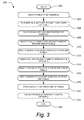
- FIG. 3 is a flow diagram of a process 300 for assembling a fastener-free primary structural joint for sandwich panels in accordance with yet another embodiment of the invention.
- the process 300 begins at a block 302 .
- the panels to be assembled are selected, such as panels 102 , 104 .
- the panels may be designed for assembly with a unique complementary panel, such as in aviation assembly where each panel may include a distinct contour.
- the panels may be trimmed or otherwise prepared before they are joined in an assembly.
- the panels 102 , 104 may include a removable core portion in the interior recess 114 , such that the removable core portion is removed at the optional block 306 .
- the panels 102 , 104 may be created or manufactured with the core 106 and skins 108 , 110 ready for assembly without removing or trimming the panels 102 , 104 .
- the panels are placed into an adjacent position for assembly, such as the intended assembled panel position.
- a plug is selected for insertion into the recess formed by the interior side of the panels.
- the plug may be designed for a particular joint assembly.
- the plug may also require removal of a portion of the plug core 122 or trimming of the plug interior surface 124 before insertion of the plug into the recess 116 formed by the panel assembly 112 .
- adhesive may be applied to the adjacent surfaces of the plug and panel assembly. For example, the underside of the plug interior surface 124 , the plug exterior skin 126 , and any surfaces exposed on the panel assembly 112 in the interior recess 114 may have adhesive applied to them at the block 312 .
- the plug is inserted into the recess formed by the interior side of the panels.
- some adhesive may necessitate removal. For example, some adhesive may be forced through the outlet gap 118 and/or out gaps near the contoured plug edges 210 and need to be removed.
- a splice is selected for attachment to the exterior side of the panels.
- the splice may be selected for insertion into the exterior recess 116 of the panel assembly 112 at the block 316 .
- adhesive is applied to the adjacent surfaces of the splice and panel assembly.
- adhesive may be applied to the surfaces of the panel assembly 112 exposed by the exterior recess 116 and the underside of the splice 128 adjacent to the exterior recess 116 .
- the splice is attached to the exterior side of the panel assembly 112 .
- the splice 128 may be inserted into the exterior recess 116 .
- the alignment mechanism may be aligned with its counterpart mechanism on the adjacent panel of the panel assembly 112 . If excess adhesive is present, it may necessitate removal from the splice 128 or panel assembly 112 .
- an adhesive or bonding agent may require curing time. Therefore, a curing process is performed at block 322 .
- the curing process includes the application of heat and pressure to the panel assembly according to a carefully controlled curing process. Clamps or other securing mechanisms may be used to maintain the assembly of the structural joint 100 during the curing process at the optional block 322 . Alternatively, adhesives with relatively quick bonding times may not require the use of securing mechanisms.
- the process 300 ends.
- the process 300 illustrates attachment of the plug 120 and the splice 128 to the panel assembly 112 using an adhesive or bonding agent
- other means of attachment may be utilized while remaining within the spirit and scope of the present disclosure.
- a plurality of snaps or locking features may be included on the mating surfaces of the plug 120 , the splice 128 , and the panel assembly 112 to facilitate assembly of the structural joint 100 .
- FIG. 4 is a plan view of fastener-free primary contoured structural joint 400 for sandwich panels in accordance with an embodiment of the invention.
- the contoured joint 400 includes first and second panels 402 , 404 , a contoured plug 420 , and a contoured splice 428 . Except for being contoured, many of the aspects of these components are substantially similar to the non-contoured embodiments described above with respect to FIGS. 1-3 , and for the sake of brevity, only significant differences will be described below.
- the contoured structural joint 400 may include a number of radii that define a contour across the panels after assembly.
- the first panel 402 may have a first radius 452 while the second panel 404 may have a second radius 454 .
- the contoured plug 420 and the contoured splice 428 may include contours that create an approximately continuous contour between the panels 402 , 404 .
- the contoured structural joint 400 may be necessary to maintain the proper design requirements of the aircraft.
- the contoured structural joint 400 may include corresponding complex contours across the contoured panels 402 , 404 , the contoured plug 420 , and the contoured splice 428 . It should also be appreciated that the thickness of a panel core 406 , plug core 422 , and skins 408 , 410 may vary based on the application of the contoured structural joint 400 , such as they may vary across any distance within the contoured structural joint.
- FIG. 5 is a side elevational view of an aircraft 500 utilizing fastener-free primary structural joints 550 for sandwich panels in accordance with yet another embodiment of the invention.
- structural joint may be employed in a wide variety of locations, including the fuselage, body, walls, and other exterior locations on movable platforms such as motor vehicles, aircraft, maritime vessels, or spacecraft, or other suitable applications including applications of building or product construction where panels are joined to create a structural joint.
- an aircraft 500 may have one or more fastener-free primary structural joints 550 for sandwich panels in accordance with an embodiment of the invention.
- the aircraft 500 includes a fuselage 502 including wing assemblies 504 , a tail assembly 506 , and a landing assembly 508 .
- the aircraft 500 further includes one or more propulsion units 510 , a control system 512 (not visible), and a host of other systems and subsystems that enable proper operation of the aircraft 500 .
- embodiments of the fastener-free primary structural joints for sandwich panels may be employed in any suitable portion of the aircraft 500 , such as in a fuselage 502 ( 550 a ), wing assemblies 504 ( 550 b ), tail assembly 506 ( 550 c ), and any other suitable areas of the aircraft 500 .
- the various components and subsystems of the aircraft 500 may be of known construction and, for the sake of brevity, will not be described in detail herein.
- the aircraft 500 shown in FIG. 5 is generally representative of a commercial passenger aircraft, including, for example, the 737, 747, 757, 767, 777, and 787 models commercially available from The Boeing Company of Chicago, Ill., the inventive apparatus and methods disclosed herein may also be employed in the assembly of virtually any other types of aircraft.
- teachings of the present disclosure may be applied to the manufacture and assembly of other passenger aircraft, fighter aircraft, cargo aircraft, rotary aircraft, and any other types of manned or unmanned aircraft, including those described, for example, in The Illustrated Encyclopedia of Military Aircraft by Enzo Angelucci, published by Book Sales Publishers, September 2001, and in Jane's All the World's Aircraft published by Jane's Information Group of Coulsdon, Surrey, United Kingdom, which texts are incorporated herein by reference.
Abstract
Description
Claims (19)
Priority Applications (4)
| Application Number | Priority Date | Filing Date | Title |
|---|---|---|---|
| US11/747,475 US8016230B2 (en) | 2007-05-11 | 2007-05-11 | Fastner-free primary structural joint for sandwich panels |
| PCT/US2008/063296 WO2009017864A2 (en) | 2007-05-11 | 2008-05-09 | Fastener-free primary structural joint for sandwich panels |
| GB0921762A GB2462773B (en) | 2007-05-11 | 2008-05-09 | Fastener-free primary structural joint for sandwich panels |
| JP2010508516A JP5298122B2 (en) | 2007-05-11 | 2008-05-09 | Main structural joints without the need for fasteners for sandwich panels |
Applications Claiming Priority (1)
| Application Number | Priority Date | Filing Date | Title |
|---|---|---|---|
| US11/747,475 US8016230B2 (en) | 2007-05-11 | 2007-05-11 | Fastner-free primary structural joint for sandwich panels |
Publications (2)
| Publication Number | Publication Date |
|---|---|
| US20100006702A1 US20100006702A1 (en) | 2010-01-14 |
| US8016230B2 true US8016230B2 (en) | 2011-09-13 |
Family
ID=40305155
Family Applications (1)
| Application Number | Title | Priority Date | Filing Date |
|---|---|---|---|
| US11/747,475 Active 2029-07-06 US8016230B2 (en) | 2007-05-11 | 2007-05-11 | Fastner-free primary structural joint for sandwich panels |
Country Status (4)
| Country | Link |
|---|---|
| US (1) | US8016230B2 (en) |
| JP (1) | JP5298122B2 (en) |
| GB (1) | GB2462773B (en) |
| WO (1) | WO2009017864A2 (en) |
Cited By (14)
| Publication number | Priority date | Publication date | Assignee | Title |
|---|---|---|---|---|
| US20090320387A1 (en) * | 2008-06-27 | 2009-12-31 | Innovida Factories, Ltd. | Sandwich panel ground anchor and ground preparation for sandwich panel structures |
| US20100005732A1 (en) * | 2008-07-10 | 2010-01-14 | Innovida Holdings, Inc. | Building roof structure having a round corner |
| US20100196733A1 (en) * | 2007-05-31 | 2010-08-05 | Airbus Operations Gmbh | Method for Producing a Composite Skin in the Field of Aeronautics and Astronautics |
| US20100237194A1 (en) * | 2007-10-31 | 2010-09-23 | Airbus Operations Gmbh | Transverse splicing plate for creating a fuselage, and a method for connecting two, in particular wound, cfp fuselage sections |
| US20130026297A1 (en) * | 2010-12-28 | 2013-01-31 | Bell Helicopter Textron Inc. | Multi-Directional Load Joint System |
| US8875475B2 (en) | 2013-03-14 | 2014-11-04 | Millport Associates S.A. | Multiple panel beams and methods |
| US20150129714A1 (en) * | 2013-11-08 | 2015-05-14 | Airbus Operations Sas | Connection device for means of airplane |
| US20150291273A1 (en) * | 2013-10-17 | 2015-10-15 | Airbus Operations Gmbh | Method of joining panels for an airframe |
| US9821538B1 (en) | 2009-06-22 | 2017-11-21 | The Boeing Company | Ribbed caul plate for attaching a strip to a panel structure and method for use |
| US10823059B2 (en) | 2018-10-03 | 2020-11-03 | General Electric Company | Acoustic core assemblies with mechanically joined acoustic core segments, and methods of mechanically joining acoustic core segments |
| US11047304B2 (en) | 2018-08-08 | 2021-06-29 | General Electric Company | Acoustic cores with sound-attenuating protuberances |
| US11059559B2 (en) | 2018-03-05 | 2021-07-13 | General Electric Company | Acoustic liners with oblique cellular structures |
| US11434819B2 (en) | 2019-03-29 | 2022-09-06 | General Electric Company | Acoustic liners with enhanced acoustic absorption and reduced drag characteristics |
| US11668236B2 (en) | 2020-07-24 | 2023-06-06 | General Electric Company | Acoustic liners with low-frequency sound wave attenuating features |
Families Citing this family (19)
| Publication number | Priority date | Publication date | Assignee | Title |
|---|---|---|---|---|
| GB0525896D0 (en) * | 2005-12-20 | 2006-02-01 | Airbus Uk Ltd | A joint for use in aircraft construction |
| US8016970B2 (en) * | 2007-08-02 | 2011-09-13 | The Boeing Company | Method for applying a pre-cured composite strip to a composite component to minimize inconsistencies appearing on a surface of the composite component |
| US8834667B2 (en) * | 2010-10-19 | 2014-09-16 | The Boeing Company | Method for joining sandwich truss core panels and composite structures produced therefrom |
| US9669579B2 (en) * | 2008-11-13 | 2017-06-06 | The Boeing Company | Aircraft skin attachment system |
| JP5439963B2 (en) * | 2009-06-12 | 2014-03-12 | 三菱電機株式会社 | Solar array panel, repair method of solar array panel |
| US8282042B2 (en) * | 2009-06-22 | 2012-10-09 | The Boeing Company | Skin panel joint for improved airflow |
| US10369772B2 (en) * | 2012-07-10 | 2019-08-06 | Textron Innovations Inc. | Method of making core-stiffened structure |
| ES2396843B1 (en) * | 2010-11-30 | 2014-01-29 | Airbus Operations, S.L. | INTERFACE PROVISION BETWEEN TWO COMPONENTS OF AN AIRCRAFT STRUCTURE USING AN INTERMEDIATE PART. |
| FR2975043B1 (en) * | 2011-05-11 | 2015-05-15 | Versaplast | COMPOSITE PANEL AND METHOD FOR PRODUCING THE SAME |
| US9352822B2 (en) | 2012-05-30 | 2016-05-31 | The Boeing Company | Bonded composite airfoil |
| US8985512B1 (en) | 2012-09-21 | 2015-03-24 | The Boeing Company | Aircraft, fuselages, and associated methods |
| DE102013102812B4 (en) * | 2013-03-19 | 2017-01-26 | Airbus Operations Gmbh | Hull structure for a means of transport, means of transport and method of making a hull structure for a means of transport |
| US8985513B2 (en) * | 2013-06-17 | 2015-03-24 | The Boeing Company | Honeycomb cores with splice joints and methods of assembling honeycomb cores |
| US9676469B2 (en) * | 2014-04-10 | 2017-06-13 | Lockheed Martin Corporation | System and method for fastening structures |
| DE102015206713A1 (en) * | 2015-04-15 | 2016-10-20 | Airbus Operations Gmbh | Kit and method for housing construction of a vehicle cabin monument |
| CA3065742A1 (en) * | 2017-06-07 | 2018-12-13 | Ihi Corporation | Sound-absorbing panel and manufacturing method for same |
| US11167836B2 (en) * | 2018-06-21 | 2021-11-09 | Sierra Nevada Corporation | Devices and methods to attach composite core to a surrounding structure |
| US20200377191A1 (en) * | 2019-05-29 | 2020-12-03 | The Boeing Company | Stringerless sandwich fuselage panels |
| CN110549632A (en) * | 2019-08-01 | 2019-12-10 | 山东双一科技股份有限公司 | Glass fiber reinforced plastic connecting structure and connecting method thereof |
Citations (20)
| Publication number | Priority date | Publication date | Assignee | Title |
|---|---|---|---|---|
| GB1349200A (en) | 1970-02-09 | 1974-03-27 | Bonnet A | Plug for the fixation of elements to a panel of friable core |
| US3806928A (en) * | 1964-03-16 | 1974-04-23 | American Rockwell Corp | Laminated sandwich construction |
| US4156054A (en) | 1978-03-09 | 1979-05-22 | Swiss Aluminium Limited | Bonded assembly and method for obtaining same |
| US4284443A (en) * | 1979-02-05 | 1981-08-18 | The Boeing Company | Single stage hot bonding method for producing composite honeycomb core structures |
| US4336090A (en) * | 1980-06-30 | 1982-06-22 | The Boeing Company | Method of making sandwich panel |
| FR2557932A1 (en) | 1984-01-10 | 1985-07-12 | Carrez Pierre | Method for butt joining two sandwich panels with a honeycomb core and composite panel obtained by this method. |
| US4662587A (en) * | 1981-09-30 | 1987-05-05 | The Boeing Company | Composite for aircraft wing and method of making |
| US4793727A (en) * | 1987-05-21 | 1988-12-27 | United Technologies Corporation | Two-step composite joint |
| US4806077A (en) * | 1986-07-28 | 1989-02-21 | Societe Nationale Industrielle Et Aerospatiale | Composite material blade with twin longeron and twin box structure having laminated honeycomb sandwich coverings and a method of manufacturing same |
| US4966802A (en) * | 1985-05-10 | 1990-10-30 | The Boeing Company | Composites made of fiber reinforced resin elements joined by adhesive |
| WO2000009321A1 (en) | 1998-08-15 | 2000-02-24 | Bae Systems Plc | Composite material construction |
| US6149749A (en) * | 1996-11-01 | 2000-11-21 | British Aerospace Public Limited Company | Repair of composite laminates |
| US6220651B1 (en) * | 1996-09-12 | 2001-04-24 | Wabash Technology Corporation | Composite joint configuration |
| US6253530B1 (en) * | 1995-09-27 | 2001-07-03 | Tracy Price | Structural honeycomb panel building system |
| US6565942B2 (en) * | 1997-12-23 | 2003-05-20 | The Boeing Company | Composite panel having a thermoplastic seam weld |
| US20040211151A1 (en) * | 2002-12-17 | 2004-10-28 | Fanucci Jerome P | Large composite structures and a process for fabricating large composite structures |
| US7182291B2 (en) * | 2005-03-23 | 2007-02-27 | The Boeing Company | Integrated aircraft structural floor |
| US7291373B2 (en) * | 2005-05-05 | 2007-11-06 | Northrop Grumman Corporation | Thermally insulated structure—full depth sandwich joint concept |
| US7554785B2 (en) * | 2004-03-23 | 2009-06-30 | The Boeing Company | Lightning damage protection for composite aircraft |
| US20100065688A1 (en) * | 2007-09-17 | 2010-03-18 | Wood Jeffrey H | Method and apparatus for reinforcing composite structures |
Family Cites Families (5)
| Publication number | Priority date | Publication date | Assignee | Title |
|---|---|---|---|---|
| JPH0853100A (en) * | 1994-08-10 | 1996-02-27 | Mitsubishi Electric Corp | Honeycomb sandwhich panel with heat pipe embedded in it |
| JP3437301B2 (en) * | 1994-12-16 | 2003-08-18 | 昭和飛行機工業株式会社 | Manufacturing method of bonding jig |
| JPH08175498A (en) * | 1994-12-26 | 1996-07-09 | Japan Airlines Co Ltd | Device used for repair of bonded structure member for aircraft |
| JPH08290497A (en) * | 1995-04-20 | 1996-11-05 | Nippon Steel Corp | Wing type honeycomb panel and its manufacture |
| US7687129B2 (en) * | 2007-01-08 | 2010-03-30 | Lockheed Martin Corporation | Splice seam |
-
2007
- 2007-05-11 US US11/747,475 patent/US8016230B2/en active Active
-
2008
- 2008-05-09 GB GB0921762A patent/GB2462773B/en active Active
- 2008-05-09 WO PCT/US2008/063296 patent/WO2009017864A2/en active Application Filing
- 2008-05-09 JP JP2010508516A patent/JP5298122B2/en active Active
Patent Citations (20)
| Publication number | Priority date | Publication date | Assignee | Title |
|---|---|---|---|---|
| US3806928A (en) * | 1964-03-16 | 1974-04-23 | American Rockwell Corp | Laminated sandwich construction |
| GB1349200A (en) | 1970-02-09 | 1974-03-27 | Bonnet A | Plug for the fixation of elements to a panel of friable core |
| US4156054A (en) | 1978-03-09 | 1979-05-22 | Swiss Aluminium Limited | Bonded assembly and method for obtaining same |
| US4284443A (en) * | 1979-02-05 | 1981-08-18 | The Boeing Company | Single stage hot bonding method for producing composite honeycomb core structures |
| US4336090A (en) * | 1980-06-30 | 1982-06-22 | The Boeing Company | Method of making sandwich panel |
| US4662587A (en) * | 1981-09-30 | 1987-05-05 | The Boeing Company | Composite for aircraft wing and method of making |
| FR2557932A1 (en) | 1984-01-10 | 1985-07-12 | Carrez Pierre | Method for butt joining two sandwich panels with a honeycomb core and composite panel obtained by this method. |
| US4966802A (en) * | 1985-05-10 | 1990-10-30 | The Boeing Company | Composites made of fiber reinforced resin elements joined by adhesive |
| US4806077A (en) * | 1986-07-28 | 1989-02-21 | Societe Nationale Industrielle Et Aerospatiale | Composite material blade with twin longeron and twin box structure having laminated honeycomb sandwich coverings and a method of manufacturing same |
| US4793727A (en) * | 1987-05-21 | 1988-12-27 | United Technologies Corporation | Two-step composite joint |
| US6253530B1 (en) * | 1995-09-27 | 2001-07-03 | Tracy Price | Structural honeycomb panel building system |
| US6220651B1 (en) * | 1996-09-12 | 2001-04-24 | Wabash Technology Corporation | Composite joint configuration |
| US6149749A (en) * | 1996-11-01 | 2000-11-21 | British Aerospace Public Limited Company | Repair of composite laminates |
| US6565942B2 (en) * | 1997-12-23 | 2003-05-20 | The Boeing Company | Composite panel having a thermoplastic seam weld |
| WO2000009321A1 (en) | 1998-08-15 | 2000-02-24 | Bae Systems Plc | Composite material construction |
| US20040211151A1 (en) * | 2002-12-17 | 2004-10-28 | Fanucci Jerome P | Large composite structures and a process for fabricating large composite structures |
| US7554785B2 (en) * | 2004-03-23 | 2009-06-30 | The Boeing Company | Lightning damage protection for composite aircraft |
| US7182291B2 (en) * | 2005-03-23 | 2007-02-27 | The Boeing Company | Integrated aircraft structural floor |
| US7291373B2 (en) * | 2005-05-05 | 2007-11-06 | Northrop Grumman Corporation | Thermally insulated structure—full depth sandwich joint concept |
| US20100065688A1 (en) * | 2007-09-17 | 2010-03-18 | Wood Jeffrey H | Method and apparatus for reinforcing composite structures |
Non-Patent Citations (1)
| Title |
|---|
| PCT Intl Search Report and Written Opinion for Application No. PCT/US2008/063296, dated Feb 23, 2009, 14 pgs. |
Cited By (24)
| Publication number | Priority date | Publication date | Assignee | Title |
|---|---|---|---|---|
| US20100196733A1 (en) * | 2007-05-31 | 2010-08-05 | Airbus Operations Gmbh | Method for Producing a Composite Skin in the Field of Aeronautics and Astronautics |
| US9314875B2 (en) * | 2007-05-31 | 2016-04-19 | Airbus Operations Gmbh | Method for producing a composite skin in the field of aeronautics and astronautics |
| US8783610B2 (en) * | 2007-10-31 | 2014-07-22 | Airbus Operations Gmbh | Transverse splicing plate for creating a fuselage, and a method for connecting two, in particular wound, CFP fuselage sections |
| US20100237194A1 (en) * | 2007-10-31 | 2010-09-23 | Airbus Operations Gmbh | Transverse splicing plate for creating a fuselage, and a method for connecting two, in particular wound, cfp fuselage sections |
| US8733033B2 (en) * | 2008-06-27 | 2014-05-27 | Millport Associates, SA | Sandwich panel ground anchor and ground preparation for sandwich panel structures |
| US20090320387A1 (en) * | 2008-06-27 | 2009-12-31 | Innovida Factories, Ltd. | Sandwich panel ground anchor and ground preparation for sandwich panel structures |
| US8782991B2 (en) | 2008-07-10 | 2014-07-22 | Millport Associates S.A. | Building roof structure having a round corner |
| US20100005732A1 (en) * | 2008-07-10 | 2010-01-14 | Innovida Holdings, Inc. | Building roof structure having a round corner |
| US9821538B1 (en) | 2009-06-22 | 2017-11-21 | The Boeing Company | Ribbed caul plate for attaching a strip to a panel structure and method for use |
| US20130026297A1 (en) * | 2010-12-28 | 2013-01-31 | Bell Helicopter Textron Inc. | Multi-Directional Load Joint System |
| US9592901B2 (en) * | 2010-12-28 | 2017-03-14 | Textron Innovations Inc. | Multi-directional load joint system |
| US8985515B2 (en) * | 2010-12-28 | 2015-03-24 | Textron Innovations Inc. | Multi-directional load joint system |
| US20150147114A1 (en) * | 2010-12-28 | 2015-05-28 | Bell Helicopter Textron Inc. | Multi-directional load joint system |
| US8875475B2 (en) | 2013-03-14 | 2014-11-04 | Millport Associates S.A. | Multiple panel beams and methods |
| US20150291273A1 (en) * | 2013-10-17 | 2015-10-15 | Airbus Operations Gmbh | Method of joining panels for an airframe |
| US10118685B2 (en) * | 2013-10-17 | 2018-11-06 | Airbus Operations Gmbh | Method of joining panels for an airframe |
| US9481445B2 (en) * | 2013-11-08 | 2016-11-01 | Airbus S.A.S. | Connection device for means of airplane |
| US20150129714A1 (en) * | 2013-11-08 | 2015-05-14 | Airbus Operations Sas | Connection device for means of airplane |
| US11059559B2 (en) | 2018-03-05 | 2021-07-13 | General Electric Company | Acoustic liners with oblique cellular structures |
| US11047304B2 (en) | 2018-08-08 | 2021-06-29 | General Electric Company | Acoustic cores with sound-attenuating protuberances |
| US11885264B2 (en) | 2018-08-08 | 2024-01-30 | General Electric Company | Acoustic cores with sound-attenuating protuberances |
| US10823059B2 (en) | 2018-10-03 | 2020-11-03 | General Electric Company | Acoustic core assemblies with mechanically joined acoustic core segments, and methods of mechanically joining acoustic core segments |
| US11434819B2 (en) | 2019-03-29 | 2022-09-06 | General Electric Company | Acoustic liners with enhanced acoustic absorption and reduced drag characteristics |
| US11668236B2 (en) | 2020-07-24 | 2023-06-06 | General Electric Company | Acoustic liners with low-frequency sound wave attenuating features |
Also Published As
| Publication number | Publication date |
|---|---|
| JP2010526729A (en) | 2010-08-05 |
| JP5298122B2 (en) | 2013-09-25 |
| US20100006702A1 (en) | 2010-01-14 |
| GB2462773A (en) | 2010-02-24 |
| GB0921762D0 (en) | 2010-01-27 |
| WO2009017864A2 (en) | 2009-02-05 |
| GB2462773B (en) | 2011-09-21 |
| WO2009017864A3 (en) | 2009-04-16 |
Similar Documents
| Publication | Publication Date | Title |
|---|---|---|
| US8016230B2 (en) | Fastner-free primary structural joint for sandwich panels | |
| US7712993B2 (en) | Double shear joint for bonding in structural applications | |
| EP2730498B1 (en) | Joint for composite wings | |
| US8758879B2 (en) | Composite hat stiffener, composite hat-stiffened pressure webs, and methods of making the same | |
| US6945727B2 (en) | Apparatuses and methods for joining structural members, such as composite structural members | |
| JP6679338B2 (en) | Panel system and method of assembling the panel system | |
| EP3204292B1 (en) | Process for assembling aircraft control surfaces | |
| EP2899117B1 (en) | Joints between a composite skin and a load-bearing component and methods of forming same | |
| EP2857186A2 (en) | Method for manufacturing a fibre composite component, fibre composite component, and structural component for an aircraft or spacecraft | |
| US10612575B2 (en) | Sandwich panel joints and methods for joining sandwich panels | |
| JP2019189209A (en) | Methods of manufacturing panel having composite stringer for vehicle | |
| EP2455625B1 (en) | Composite sandwich shell edge joint | |
| US20160089830A1 (en) | Joining structural members using foam | |
| US8973241B1 (en) | Method and apparatus for joining composite structures | |
| US7748119B2 (en) | Method for manufacturing composite components | |
| EP3199336B1 (en) | Sandwich panel assembly and method | |
| JP2011518722A (en) | A system that connects the backing and the structural elements that support it | |
| US10414480B2 (en) | Sidewall mounting hardware for aircraft | |
| US11358348B2 (en) | Mold insert for use with a mandrel for forming a composite structure | |
| US20060071124A1 (en) | Reinforced structural assembly having a lap joint and method for forming the same | |
| US20160332412A1 (en) | Process or system to reduce cost and weight of aerospace interior structural thermoplastic or composite panel constructions | |
| US20060070345A1 (en) | Reinforced structural assembly having a tee joint and method for forming the same | |
| KR20210003734A (en) | Composite structural element |
Legal Events
| Date | Code | Title | Description |
|---|---|---|---|
| AS | Assignment |
Owner name: BOEING COMPANY, ILLINOIS Free format text: ASSIGNMENT OF ASSIGNORS INTEREST;ASSIGNORS:FOGARTY, JOHN H.;RETZ, KEVIN M.;REEL/FRAME:019295/0849 Effective date: 20070509 |
|
| FEPP | Fee payment procedure |
Free format text: PAYOR NUMBER ASSIGNED (ORIGINAL EVENT CODE: ASPN); ENTITY STATUS OF PATENT OWNER: LARGE ENTITY |
|
| STCF | Information on status: patent grant |
Free format text: PATENTED CASE |
|
| FPAY | Fee payment |
Year of fee payment: 4 |
|
| MAFP | Maintenance fee payment |
Free format text: PAYMENT OF MAINTENANCE FEE, 8TH YEAR, LARGE ENTITY (ORIGINAL EVENT CODE: M1552); ENTITY STATUS OF PATENT OWNER: LARGE ENTITY Year of fee payment: 8 |
|
| MAFP | Maintenance fee payment |
Free format text: PAYMENT OF MAINTENANCE FEE, 12TH YEAR, LARGE ENTITY (ORIGINAL EVENT CODE: M1553); ENTITY STATUS OF PATENT OWNER: LARGE ENTITY Year of fee payment: 12 |