US8011744B2 - Refrigerator with tray cover - Google Patents
Refrigerator with tray cover Download PDFInfo
- Publication number
- US8011744B2 US8011744B2 US12/071,796 US7179608A US8011744B2 US 8011744 B2 US8011744 B2 US 8011744B2 US 7179608 A US7179608 A US 7179608A US 8011744 B2 US8011744 B2 US 8011744B2
- Authority
- US
- United States
- Prior art keywords
- front cover
- disposed
- shelf
- storage tray
- support
- Prior art date
- Legal status (The legal status is an assumption and is not a legal conclusion. Google has not performed a legal analysis and makes no representation as to the accuracy of the status listed.)
- Expired - Fee Related, expires
Links
- 238000001816 cooling Methods 0.000 description 22
- 235000013305 food Nutrition 0.000 description 8
- 238000007710 freezing Methods 0.000 description 4
- 230000008014 freezing Effects 0.000 description 4
- 230000008901 benefit Effects 0.000 description 3
- 235000013311 vegetables Nutrition 0.000 description 3
- 239000002826 coolant Substances 0.000 description 2
- 239000000284 extract Substances 0.000 description 2
- VNWKTOKETHGBQD-UHFFFAOYSA-N methane Chemical compound C VNWKTOKETHGBQD-UHFFFAOYSA-N 0.000 description 2
- 241000251468 Actinopterygii Species 0.000 description 1
- 230000006835 compression Effects 0.000 description 1
- 238000007906 compression Methods 0.000 description 1
- 230000005494 condensation Effects 0.000 description 1
- 238000009833 condensation Methods 0.000 description 1
- 235000013399 edible fruits Nutrition 0.000 description 1
Images


Classifications
-
- A—HUMAN NECESSITIES
- A47—FURNITURE; DOMESTIC ARTICLES OR APPLIANCES; COFFEE MILLS; SPICE MILLS; SUCTION CLEANERS IN GENERAL
- A47B—TABLES; DESKS; OFFICE FURNITURE; CABINETS; DRAWERS; GENERAL DETAILS OF FURNITURE
- A47B96/00—Details of cabinets, racks or shelf units not covered by a single one of groups A47B43/00 - A47B95/00; General details of furniture
- A47B96/02—Shelves
-
- F—MECHANICAL ENGINEERING; LIGHTING; HEATING; WEAPONS; BLASTING
- F25—REFRIGERATION OR COOLING; COMBINED HEATING AND REFRIGERATION SYSTEMS; HEAT PUMP SYSTEMS; MANUFACTURE OR STORAGE OF ICE; LIQUEFACTION SOLIDIFICATION OF GASES
- F25D—REFRIGERATORS; COLD ROOMS; ICE-BOXES; COOLING OR FREEZING APPARATUS NOT OTHERWISE PROVIDED FOR
- F25D25/00—Charging, supporting, and discharging the articles to be cooled
- F25D25/02—Charging, supporting, and discharging the articles to be cooled by shelves
-
- F—MECHANICAL ENGINEERING; LIGHTING; HEATING; WEAPONS; BLASTING
- F25—REFRIGERATION OR COOLING; COMBINED HEATING AND REFRIGERATION SYSTEMS; HEAT PUMP SYSTEMS; MANUFACTURE OR STORAGE OF ICE; LIQUEFACTION SOLIDIFICATION OF GASES
- F25D—REFRIGERATORS; COLD ROOMS; ICE-BOXES; COOLING OR FREEZING APPARATUS NOT OTHERWISE PROVIDED FOR
- F25D23/00—General constructional features
- F25D23/02—Doors; Covers
- F25D23/021—Sliding doors
-
- F—MECHANICAL ENGINEERING; LIGHTING; HEATING; WEAPONS; BLASTING
- F25—REFRIGERATION OR COOLING; COMBINED HEATING AND REFRIGERATION SYSTEMS; HEAT PUMP SYSTEMS; MANUFACTURE OR STORAGE OF ICE; LIQUEFACTION SOLIDIFICATION OF GASES
- F25D—REFRIGERATORS; COLD ROOMS; ICE-BOXES; COOLING OR FREEZING APPARATUS NOT OTHERWISE PROVIDED FOR
- F25D25/00—Charging, supporting, and discharging the articles to be cooled
- F25D25/02—Charging, supporting, and discharging the articles to be cooled by shelves
- F25D25/021—Charging, supporting, and discharging the articles to be cooled by shelves combined with trays
-
- A—HUMAN NECESSITIES
- A47—FURNITURE; DOMESTIC ARTICLES OR APPLIANCES; COFFEE MILLS; SPICE MILLS; SUCTION CLEANERS IN GENERAL
- A47B—TABLES; DESKS; OFFICE FURNITURE; CABINETS; DRAWERS; GENERAL DETAILS OF FURNITURE
- A47B2210/00—General construction of drawers, guides and guide devices
- A47B2210/17—Drawers used in connection with household appliances
Definitions
- the present invention relates to a refrigerator including a support portion and a holder portion to prevent a central portion of a front cover from drooping down when a storage tray is opened.
- a refrigerator is an apparatus to store food in a fresh state by heat exchange based on a temperature difference generated in a phase change of a coolant during the compression, condensation, and expansion of the coolant, such as Freon or methane, for example.
- the refrigerator includes a main body serving as an external body, a freezing chamber and a cooling chamber which are disposed in the main body as storage chambers with open front surfaces, and doors hinge-coupled to a front portion of the main body to open and close the freezing chamber and the cooling chamber.
- a plurality of shelves is respectively provided in the freezing chamber and the cooling chamber such that food can be stored on the shelves. Recently, a separate space maintained at a separate temperature range is disposed in the refrigerator to provide an optimal temperature range according to types of food.
- a vegetable compartment to store vegetables and fruits and a special cooling room to store food, such as fish that specially requires freshness, are installed in a drawer at a lower side of the cooling chamber.
- a user can control the temperature of the chambers such that the freezing chamber is maintained at a temperature range of about ⁇ 12° C. to ⁇ 24° C., for example, and the cooling chamber is maintained at a temperature range of about 0° C. to 7° C., for example.
- the vegetable compartment is maintained at a temperature range of about 5° C. to 10° C., for example, and the special cooling room is maintained at a temperature range of about 1° C. to 3° C., for example.
- a shelf to store food is loaded on a guide rail formed on an inner wall of the main body to form a separate space such that the shelf can slide and be extracted.
- a cover is installed at a front side of the shelf to prevent leakage of cool air from the space to form the special cooling room.
- a width of the front cover is also enlarged. Since the front cover is vertically rotated by hinges provided at opposite sides, a central portion of the front cover tends to droop.
- the drooping of the front cover makes it difficult to maintain the special cooling room at a proper temperature.
- the drooping of the front cover may cause deformation or detachment of the front cover in the long run. Further, the drooping of the front cover may degrade an appearance of the refrigerator.
- the present embodiments have been made in order to solve the above problems. It is an aspect of the embodiments to prevent a central portion of a front cover from drooping down and prevent the deformation or detachment of the front cover.
- a refrigerator including: a main body; a receiving portion defined within the main body; a shelf disposed within the receiving portion having at least one auxiliary hinge portion disposed at a rear thereof; a storage tray slidably extractable from within the receiving portion and adjacent the shelf when the storage tray is received within the receiving portion; and a front cover disposed on a front surface of the storage tray to be rotated upward and opened when the storage tray is extracted from within the receiving portion and having at least one holder portion disposed on a rear surface thereof to be coupled to the at least one auxiliary hinge portion.
- the front cover may include hinge shafts disposed at opposite sites thereof and the main body may include internal opposite sidewalls and hinge grooves defined therein at the opposite sidewalls, the hinge shafts being receivable into the hinge grooves.
- the at least one auxiliary hinge portion may include an auxiliary hinge shaft, the hinge shafts of the front cover and the auxiliary hinge shaft being disposed along a same axis.
- the at least one auxiliary hinge portion may include an auxiliary hinge shaft coupled to the holder portion of the front cover when the front cover is attached to the auxiliary hinge portion and a support portion extended backward and bent from at least one side of the auxiliary hinge shaft to be connected to the shelf.
- the at least one auxiliary hinge portion may include a groove defined within the at least one support portion such that an upper portion of the front cover is insertable into the groove when the front cover is opened in an upward direction.
- the at least one auxiliary hinge portion may include at least one support portion protruded forward from the shelf and auxiliary hinge shafts disposed at opposite side portions of the at least one support portion to be coupled to the holder portion.
- a groove may be defined within the at least one support portion such that an upper portion of the front cover is insertable into the groove when the front cover is opened in an upward direction.
- the storage tray may further include a sidewall to be extended upward and bent having an inclined portion disposed at a front side thereof, and wherein the front cover includes support pieces disposed at opposite sides of the front cover to come into contact with the inclined portion of the sidewall such that the inclined portion pushes the support pieces such that the front cover is rotated upward and opened when the storage tray is extracted forward.
- a refrigerator including: a main body; a receiving portion defined within the main body; a shelf disposed within the receiving portion and including at least one support portion disposed at a portion thereof; a storage tray slidably extractable from within the receiving portion and adjacent the shelf when the storage tray is received within the receiving portion; and a front cover disposed on a front surface of the storage tray to be rotated upward and opened when the storage tray is extracted from within the receiving portion and including at least one auxiliary hinge portion disposed a rear surface thereof to be coupled to the at least one support portion.
- the at least one auxiliary hinge portion may include an auxiliary hinge shaft coupled to the at least one support portion and a connecting portion extended and bent backward from at least one side of the auxiliary hinge shaft and connected to a rear surface of the front cover, a holder portion is disposed at the at least one support portion and protruded upward from the shelf to be coupled to the auxiliary hinge shaft, and a groove defined within the at least one support portion such that an upper portion of the front cover is insertable into the groove when the front cover is opened upward.
- the at least one auxiliary hinge portion may include a connecting portion protruded from a rear surface of the front cover and auxiliary hinge shafts disposed at opposite sides of the connecting portion, a holder portion is disposed at the at least one support portion and protruded upward from the shelf to be coupled to the auxiliary hinge shafts, and a groove is defined within the at least one support portion such that an upper portion of the front cover is insertable into the groove when the front cover is opened upward.
- the storage tray may include a sidewall to be extended upward and bent having an inclined portion disposed at a front side thereof, and wherein the front cover includes support pieces disposed at opposite sides of the front cover to come into contact with the inclined portion of the sidewall such that the inclined portion pushes the support pieces such that the front cover is rotated upward and opened when the storage tray is extracted forward.
- the front cover may include hinge shafts disposed at opposite sides thereof and the main body includes internal opposite sidewalls and hinge grooves defined therein at the opposite sidewalls, the hinge shafts being receivable into the hinge grooves.
- a refrigerator having a main body, including: a shelf disposed within the main body and including at least one auxiliary hinge portion; and a front cover to cover a storage tray receivable within the main body, the front cover having at least one holder portion disposed on a rear surface thereof to be coupled to the at least one auxiliary hinge portion.
- FIG. 1 shows an entire perspective view of a refrigerator according to a first embodiment
- FIG. 2 shows an exploded view of a storage tray of the refrigerator according to the first embodiment
- FIG. 3 shows a partial perspective view of an auxiliary hinge portion of the refrigerator according to the first embodiment
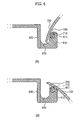
- FIGS. 4A and 4B illustrate a partial cross-sectional view showing an operation of auxiliary hinge shafts and holder portions of the refrigerator according to the first embodiment
- FIG. 5 shows a partial perspective view of an auxiliary hinge portion of the refrigerator according to a second embodiment
- FIGS. 6A and 6B illustrate a partial cross-sectional view showing an operation of an auxiliary hinge shaft and a holder portion of the refrigerator according to the second embodiment.
- FIG. 1 shows an entire perspective view of a refrigerator according to the first embodiment.
- FIG. 2 shows an exploded view of a storage tray of the refrigerator according to the first embodiment.
- FIG. 3 shows a partial perspective view of an auxiliary hinge portion of the refrigerator according to the first embodiment.
- a special cooling room is disposed at a lower portion of a cooling chamber 104 in this embodiment, the special cooling room may be disposed at an upper portion of the cooling chamber 104 .
- a receiving portion 300 is disposed in an inner housing of a main body 100 to receive a storage tray 200 .
- An upper shelf 320 is used to separate the receiving portion 300 from another portion of the cooling chamber 104 .
- a lower shelf is disposed at a lower portion of the receiving portion 300 to separate the receiving portion 300 from the other portion of the cooling chamber 104 .
- the inside of the receiving portion 300 is used as a special cooling room which is maintained at a temperature of about 1° C. to 3° C., for example, to store food that specially requires freshness.
- a controller may be provided to vary the temperature distribution to store food which needs different treatment according to user demands.
- guide rails or guide rollers may be attached to inner opposite sides of the receiving portion 300 to be coupled to guide portions which may be provided at opposite sides of the storage tray 200 such that the storage tray 200 can be smoothly retracted into or extracted from the receiving portion 300 .
- the storage tray 200 is received in the receiving portion 300 and is slidably extracted forward.
- a handle 230 can be attached to a front portion of the storage tray 200 such that a user can grasp and pull the handle 230 .
- a sidewall 210 which is extended upward and bent is disposed around the storage tray 200 , thereby preventing food from going outside of the storage tray 200 .
- Inclined portions 220 are disposed at front opposite sides of the sidewall 210 of the storage tray 200 .
- a front portion of the sidewall 210 connected to the inclined portions 220 has a smaller height than a rear portion of the sidewall 210 .
- Irregularities may be formed at the bottom of the storage tray 200 and the sidewall 210 to reinforce the strength of the storage tray 200 .
- a front cover 400 is slidable extractable into and out of the receiving portion 300 to separate the special cooling room from the other portion of the cooling chamber.
- Hinge shafts 420 are provided at opposite sides of the front cover 400 .
- Hinge grooves 330 are provided at opposite sidewalls of the receiving portion 300 to be coupled to the hinge shafts 420 . Accordingly, the front cover 400 can rotate up and down with respect to the hinge shafts 420 .
- a transparent window may be disposed at the front cover 400 to discriminate between stored products.
- Support pieces 430 are disposed at opposite sides of the front cover 400 .
- the support pieces 430 are formed in a soft round shape, for example, but may be formed in any shape capable of being received into the cooling chamber.
- the support pieces 430 are in contact with the inclined portions 220 of the storage tray 200 when the front cover 400 is closed. Accordingly, as the user extracts the storage tray 200 in a forward direction, the inclined portions 220 push the support pieces 430 when the front cover 400 is rotated upward and opened.
- auxiliary hinge portions 310 (shown in FIG. 3 ) is disposed in the receiving portion 300 adjacent to a rear upper portion of the front cover 400 .
- Holder portions 410 capable of being elastically and detachably coupled to the auxiliary hinge portions 310 are disposed on the rear surface of the front cover 400 .
- FIG. 3 illustrates the auxiliary hinge portions 310 being disposed at a front portion of the upper shelf 320 .
- the auxiliary hinge portions 310 include auxiliary hinge shafts 311 which are coupled to the holder portions 410 when the front cover 400 is attached to the auxiliary hinge portions 310 and support portions 312 which are extended and bent backward from the auxiliary hinge shafts 311 to be connected to a front portion of the upper shelf 320 , respectively.
- the support portions 312 may be disposed only at one side or at opposite sides of the respective auxiliary hinge shafts 311 .
- FIG. 3 shows a configuration in which the support portions 312 are disposed at opposite sides of the auxiliary hinge shafts 311 .
- auxiliary hinge shafts may be disposed at opposite left and right sides of each support portion and each holder portion may have two portions which are coupled to the auxiliary hinge shafts.
- the auxiliary hinge shafts 311 and the hinge shafts 420 are disposed along the same axis, but may be disposed along different axes.
- the front portion of the support portions 312 is formed to have a soft curved surface, for example, such that the front cover 400 can be smoothly rotated onto the support portions 312 . Further, when the front cover 400 is opened upward, an upper portion of the front cover 400 may interfere with the support portions 312 to block the opening of the front cover 400 .
- grooves 313 may be formed on the support portions 312 such that the upper portion of the front cover 400 can be inserted into the grooves 313 .
- the support portions 312 may be reinforced to have a sufficient stiffness to prevent deformation and detachment of the front cover 400 and endure an external impact. Although two support portions 312 are shown in this embodiment, a different number of the support portions 312 may be provided according to the size of the refrigerator or a structural calculation.
- FIG. 4 illustrates a partial cross-sectional view showing an operation of the auxiliary hinge shafts 311 of the auxiliary hinge portions 310 and the holder portions 410 of the front cover 400 according to the first embodiment.
- the inclined portions 220 of the storage tray 200 push the support pieces 430 disposed at rear opposite sides of the front cover 400 , and the front cover 400 is rotated upward and opened by the hinge shafts 420 .
- the front cover 400 is rotated while the holder portions 410 of the front cover 400 are coupled to the auxiliary hinge shafts 311 of the auxiliary hinge portions 310 , thereby preventing a central portion of the front cover 400 from drooping.
- FIG. 5 shows a partial perspective view of an auxiliary hinge portion of the refrigerator according to the second embodiment.
- FIG. 6 illustrates a partial cross-sectional view showing an operation of an auxiliary hinge shaft and a holder portion of the refrigerator according to the second embodiment.
- the auxiliary hinge portion according to the second embodiment includes an auxiliary hinge shaft 710 is disposed on a rear surface of a front cover 700 (shown in FIG. 6 ).
- the auxiliary hinge portion according to the second embodiment further includes a connecting portion 720 which is rounded and extended at one side or at opposite sides of the auxiliary hinge shaft 710 is formed to connect the auxiliary hinge shaft 710 to the front cover 700 .
- a support portion 612 is disposed on a front portion of an upper shelf 620 to be coupled to the auxiliary hinge shaft 710 .
- the support portion 612 is formed to be protruded forward from the front surface of an upper shelf 620 .
- a holder portion 611 is disposed at a front upper side of the support portion 612 to be coupled to the auxiliary hinge shaft 710 .
- An opened portion of the holder portion 611 may be disposed at a rear side to prevent detachment of the front cover 700 .
- the support portion 612 includes a groove 613 into which an upper portion of the front cover 700 may be inserted.
- auxiliary hinge shafts may be disposed at opposite left and right sides of a connecting portion.
- a holder portion disposed at an upper end of a support portion may have two portions, or two support portions may be disposed such that the support portions are coupled to the auxiliary hinge shafts.
- FIG. 6 illustrates a partial cross-sectional view showing the operation of the auxiliary hinge shaft and the holder portion of the refrigerator according to the second embodiment.
- the auxiliary hinge shaft 710 connected to the front cover 700 is restricted into the holder portion 611 of the support portion 612 , thereby preventing deformation and detachment of the front cover in the rotation.
- the width of the storage tray is also enlarged and the front cover tends to droop or be deformed.
- the front cover is structurally reinforced. Further, it is possible to prevent the front cover from drooping and prevent a gap between the front cover and the upper shelf. Furthermore, it is possible to improve an appearance.
Abstract
Description
Claims (7)
Applications Claiming Priority (2)
| Application Number | Priority Date | Filing Date | Title |
|---|---|---|---|
| KR1020070019186A KR101095562B1 (en) | 2007-02-26 | 2007-02-26 | refrigerator |
| KR10-2007-0019186 | 2007-02-26 |
Publications (2)
| Publication Number | Publication Date |
|---|---|
| US20080203876A1 US20080203876A1 (en) | 2008-08-28 |
| US8011744B2 true US8011744B2 (en) | 2011-09-06 |
Family
ID=39715074
Family Applications (1)
| Application Number | Title | Priority Date | Filing Date |
|---|---|---|---|
| US12/071,796 Expired - Fee Related US8011744B2 (en) | 2007-02-26 | 2008-02-26 | Refrigerator with tray cover |
Country Status (2)
| Country | Link |
|---|---|
| US (1) | US8011744B2 (en) |
| KR (1) | KR101095562B1 (en) |
Cited By (2)
| Publication number | Priority date | Publication date | Assignee | Title |
|---|---|---|---|---|
| US20130174743A1 (en) * | 2012-01-06 | 2013-07-11 | B/E Aerospace, Inc. | Aircraft brewing apparatus |
| US20180274849A1 (en) * | 2017-03-21 | 2018-09-27 | Bsh Hausgeraete Gmbh | Refrigerator |
Families Citing this family (10)
| Publication number | Priority date | Publication date | Assignee | Title |
|---|---|---|---|---|
| BRMU8702530U2 (en) * | 2007-12-17 | 2009-08-11 | Whirlpool Sa | mobile shelf for refrigerators and freezers |
| KR101554852B1 (en) * | 2008-03-06 | 2015-09-23 | 삼성전자 주식회사 | Refrigerator |
| US8566353B2 (en) * | 2008-06-03 | 2013-10-22 | Google Inc. | Web-based system for collaborative generation of interactive videos |
| US8348362B2 (en) * | 2009-02-27 | 2013-01-08 | Electrolux Home Products, Inc. | Pivoting lid for refrigerator door |
| US9010145B2 (en) * | 2009-06-01 | 2015-04-21 | Samsung Electronics Co., Ltd. | Refrigerator |
| US20110048059A1 (en) * | 2009-08-27 | 2011-03-03 | Samsung Electronics Co., Ltd. | Kimchi refrigerator |
| KR101631091B1 (en) * | 2010-11-22 | 2016-06-17 | 삼성전자 주식회사 | Refrigerator and receptacle assembly thereof |
| IT1403467B1 (en) * | 2010-12-16 | 2013-10-17 | Whirlpool Co | REFRIGERABLE COMPARTMENT FOR REFRIGERATOR |
| US11168936B2 (en) * | 2017-08-01 | 2021-11-09 | Whirlpool Corporation | Storage bin assembly for a refrigerator |
| WO2023274713A1 (en) * | 2021-06-28 | 2023-01-05 | BSH Hausgeräte GmbH | A shelf assembly for installation in household cooling appliances |
Citations (11)
| Publication number | Priority date | Publication date | Assignee | Title |
|---|---|---|---|---|
| US2132737A (en) * | 1937-04-07 | 1938-10-11 | Estate Stove Co | Stove |
| US2246342A (en) * | 1940-05-06 | 1941-06-17 | Joseph D Brown | Humidity drawer |
| US2381598A (en) * | 1944-03-18 | 1945-08-07 | Philco Corp | Refrigerator cabinet construction |
| US3339994A (en) * | 1966-01-20 | 1967-09-05 | American Motors Corp | Variable capacity food compartment |
| US3471874A (en) * | 1967-12-22 | 1969-10-14 | American Standard Inc | Easily removed toilet seat |
| US4732435A (en) * | 1986-11-07 | 1988-03-22 | Whirlpool Corporation | Refrigerator crisper drawer structure |
| US5947573A (en) * | 1997-11-12 | 1999-09-07 | Whirlpool Corporation | Refrigerator and compartment therefor |
| KR20040056342A (en) | 2002-12-23 | 2004-06-30 | 엘지전자 주식회사 | Mounting structure of vegetable box in refrigerator |
| US6834922B2 (en) * | 2002-04-24 | 2004-12-28 | Lg Electronics Inc. | Vegetable compartment in refrigerator |
| US20050073226A1 (en) * | 2001-10-22 | 2005-04-07 | Antos John M | Refrigeration storage bin including flip-top cover |
| KR20060032686A (en) | 2004-10-13 | 2006-04-18 | 엘지전자 주식회사 | A withdrawal shelf for refrigerator |
Family Cites Families (1)
| Publication number | Priority date | Publication date | Assignee | Title |
|---|---|---|---|---|
| KR200158629Y1 (en) | 1997-09-27 | 1999-10-15 | 윤종용 | Chilled room of refrigerator |
-
2007
- 2007-02-26 KR KR1020070019186A patent/KR101095562B1/en not_active IP Right Cessation
-
2008
- 2008-02-26 US US12/071,796 patent/US8011744B2/en not_active Expired - Fee Related
Patent Citations (11)
| Publication number | Priority date | Publication date | Assignee | Title |
|---|---|---|---|---|
| US2132737A (en) * | 1937-04-07 | 1938-10-11 | Estate Stove Co | Stove |
| US2246342A (en) * | 1940-05-06 | 1941-06-17 | Joseph D Brown | Humidity drawer |
| US2381598A (en) * | 1944-03-18 | 1945-08-07 | Philco Corp | Refrigerator cabinet construction |
| US3339994A (en) * | 1966-01-20 | 1967-09-05 | American Motors Corp | Variable capacity food compartment |
| US3471874A (en) * | 1967-12-22 | 1969-10-14 | American Standard Inc | Easily removed toilet seat |
| US4732435A (en) * | 1986-11-07 | 1988-03-22 | Whirlpool Corporation | Refrigerator crisper drawer structure |
| US5947573A (en) * | 1997-11-12 | 1999-09-07 | Whirlpool Corporation | Refrigerator and compartment therefor |
| US20050073226A1 (en) * | 2001-10-22 | 2005-04-07 | Antos John M | Refrigeration storage bin including flip-top cover |
| US6834922B2 (en) * | 2002-04-24 | 2004-12-28 | Lg Electronics Inc. | Vegetable compartment in refrigerator |
| KR20040056342A (en) | 2002-12-23 | 2004-06-30 | 엘지전자 주식회사 | Mounting structure of vegetable box in refrigerator |
| KR20060032686A (en) | 2004-10-13 | 2006-04-18 | 엘지전자 주식회사 | A withdrawal shelf for refrigerator |
Cited By (3)
| Publication number | Priority date | Publication date | Assignee | Title |
|---|---|---|---|---|
| US20130174743A1 (en) * | 2012-01-06 | 2013-07-11 | B/E Aerospace, Inc. | Aircraft brewing apparatus |
| US20180274849A1 (en) * | 2017-03-21 | 2018-09-27 | Bsh Hausgeraete Gmbh | Refrigerator |
| US10495372B2 (en) * | 2017-03-21 | 2019-12-03 | Bsh Hausgeraete Gmbh | Refrigerator |
Also Published As
| Publication number | Publication date |
|---|---|
| KR20080079102A (en) | 2008-08-29 |
| KR101095562B1 (en) | 2011-12-19 |
| US20080203876A1 (en) | 2008-08-28 |
Similar Documents
| Publication | Publication Date | Title |
|---|---|---|
| US8011744B2 (en) | Refrigerator with tray cover | |
| USRE46029E1 (en) | Refrigerator with receiving box | |
| US9464841B2 (en) | Refrigerator | |
| US8894167B2 (en) | Refrigerator | |
| US8640482B2 (en) | Refrigerator having folding shelf | |
| US20080168794A1 (en) | Refrigerator | |
| EP2775238B1 (en) | Refrigerator | |
| EP2314965B1 (en) | Refrigerator with split type shelves | |
| US20060213852A1 (en) | Beverage refrigerator | |
| EP2175218B1 (en) | Refrigerator | |
| US9562714B2 (en) | Refrigerator | |
| US20080202146A1 (en) | Drawer type receiving device of a refrigerator | |
| US20110174012A1 (en) | Refrigerator | |
| JP2006078168A (en) | Double drawer of refrigerator | |
| KR101741392B1 (en) | Refrigerator comprising shelf which is automatically drawn out | |
| KR20170093530A (en) | Refrigerator | |
| KR200459216Y1 (en) | Refrigerator | |
| RU2438079C2 (en) | Refrigerator | |
| JP2010038497A (en) | Refrigerator | |
| US20210310722A1 (en) | Refrigerator | |
| KR101495353B1 (en) | A refrigerator | |
| KR101611610B1 (en) | A refrigerator | |
| JP2011214725A (en) | Refrigerator | |
| KR20100007495A (en) | Refrigerator | |
| KR101988308B1 (en) | Refrigerator |
Legal Events
| Date | Code | Title | Description |
|---|---|---|---|
| AS | Assignment |
Owner name: SAMSUNG ELECTRONICS CO., LTD., KOREA, REPUBLIC OF Free format text: ASSIGNMENT OF ASSIGNORS INTEREST;ASSIGNORS:LIM, JAE HOON;SHIN, YOUN TAE;REEL/FRAME:020752/0156 Effective date: 20080321 Owner name: SAMSUNG ELECTRONICS CO., LTD.,KOREA, REPUBLIC OF Free format text: ASSIGNMENT OF ASSIGNORS INTEREST;ASSIGNORS:LIM, JAE HOON;SHIN, YOUN TAE;REEL/FRAME:020752/0156 Effective date: 20080321 |
|
| STCF | Information on status: patent grant |
Free format text: PATENTED CASE |
|
| FEPP | Fee payment procedure |
Free format text: PAYOR NUMBER ASSIGNED (ORIGINAL EVENT CODE: ASPN); ENTITY STATUS OF PATENT OWNER: LARGE ENTITY |
|
| FPAY | Fee payment |
Year of fee payment: 4 |
|
| FEPP | Fee payment procedure |
Free format text: MAINTENANCE FEE REMINDER MAILED (ORIGINAL EVENT CODE: REM.); ENTITY STATUS OF PATENT OWNER: LARGE ENTITY |
|
| LAPS | Lapse for failure to pay maintenance fees |
Free format text: PATENT EXPIRED FOR FAILURE TO PAY MAINTENANCE FEES (ORIGINAL EVENT CODE: EXP.); ENTITY STATUS OF PATENT OWNER: LARGE ENTITY |
|
| STCH | Information on status: patent discontinuation |
Free format text: PATENT EXPIRED DUE TO NONPAYMENT OF MAINTENANCE FEES UNDER 37 CFR 1.362 |
|
| FP | Lapsed due to failure to pay maintenance fee |
Effective date: 20190906 |