US8009590B2 - Method for linking several communication busses using wireless links - Google Patents
Method for linking several communication busses using wireless links Download PDFInfo
- Publication number
- US8009590B2 US8009590B2 US10/399,606 US39960603A US8009590B2 US 8009590 B2 US8009590 B2 US 8009590B2 US 39960603 A US39960603 A US 39960603A US 8009590 B2 US8009590 B2 US 8009590B2
- Authority
- US
- United States
- Prior art keywords
- bus
- portal
- wireless
- connection
- reset
- Prior art date
- Legal status (The legal status is an assumption and is not a legal conclusion. Google has not performed a legal analysis and makes no representation as to the accuracy of the status listed.)
- Expired - Fee Related, expires
Links
- 238000000034 method Methods 0.000 title claims abstract description 72
- 238000004891 communication Methods 0.000 title claims abstract description 11
- 230000008569 process Effects 0.000 claims description 19
- 230000001902 propagating effect Effects 0.000 claims description 2
- 238000002372 labelling Methods 0.000 claims 3
- 230000004044 response Effects 0.000 description 17
- 230000005540 biological transmission Effects 0.000 description 12
- 238000010586 diagram Methods 0.000 description 8
- 230000007246 mechanism Effects 0.000 description 8
- 230000008859 change Effects 0.000 description 4
- 230000008901 benefit Effects 0.000 description 3
- 230000001960 triggered effect Effects 0.000 description 3
- 230000009471 action Effects 0.000 description 2
- 238000004458 analytical method Methods 0.000 description 2
- 238000005516 engineering process Methods 0.000 description 2
- 230000004048 modification Effects 0.000 description 2
- 238000012986 modification Methods 0.000 description 2
- 230000000644 propagated effect Effects 0.000 description 2
- 238000012360 testing method Methods 0.000 description 2
- 101800000560 Protein M1' Proteins 0.000 description 1
- 238000010276 construction Methods 0.000 description 1
- 230000001934 delay Effects 0.000 description 1
- 238000001514 detection method Methods 0.000 description 1
- 230000000977 initiatory effect Effects 0.000 description 1
- 238000003752 polymerase chain reaction Methods 0.000 description 1
- 238000010187 selection method Methods 0.000 description 1
Images


Classifications
-
- H—ELECTRICITY
- H04—ELECTRIC COMMUNICATION TECHNIQUE
- H04L—TRANSMISSION OF DIGITAL INFORMATION, e.g. TELEGRAPHIC COMMUNICATION
- H04L12/00—Data switching networks
- H04L12/28—Data switching networks characterised by path configuration, e.g. LAN [Local Area Networks] or WAN [Wide Area Networks]
- H04L12/40—Bus networks
- H04L12/40052—High-speed IEEE 1394 serial bus
- H04L12/40091—Bus bridging
-
- H—ELECTRICITY
- H04—ELECTRIC COMMUNICATION TECHNIQUE
- H04L—TRANSMISSION OF DIGITAL INFORMATION, e.g. TELEGRAPHIC COMMUNICATION
- H04L12/00—Data switching networks
- H04L12/28—Data switching networks characterised by path configuration, e.g. LAN [Local Area Networks] or WAN [Wide Area Networks]
- H04L12/46—Interconnection of networks
- H04L12/4604—LAN interconnection over a backbone network, e.g. Internet, Frame Relay
- H04L12/462—LAN interconnection over a bridge based backbone
- H04L12/4625—Single bridge functionality, e.g. connection of two networks over a single bridge
-
- H—ELECTRICITY
- H04—ELECTRIC COMMUNICATION TECHNIQUE
- H04L—TRANSMISSION OF DIGITAL INFORMATION, e.g. TELEGRAPHIC COMMUNICATION
- H04L12/00—Data switching networks
- H04L12/64—Hybrid switching systems
-
- H—ELECTRICITY
- H04—ELECTRIC COMMUNICATION TECHNIQUE
- H04L—TRANSMISSION OF DIGITAL INFORMATION, e.g. TELEGRAPHIC COMMUNICATION
- H04L41/00—Arrangements for maintenance, administration or management of data switching networks, e.g. of packet switching networks
- H04L41/08—Configuration management of networks or network elements
- H04L41/0803—Configuration setting
- H04L41/0806—Configuration setting for initial configuration or provisioning, e.g. plug-and-play
-
- H—ELECTRICITY
- H04—ELECTRIC COMMUNICATION TECHNIQUE
- H04L—TRANSMISSION OF DIGITAL INFORMATION, e.g. TELEGRAPHIC COMMUNICATION
- H04L41/00—Arrangements for maintenance, administration or management of data switching networks, e.g. of packet switching networks
- H04L41/12—Discovery or management of network topologies
-
- H—ELECTRICITY
- H04—ELECTRIC COMMUNICATION TECHNIQUE
- H04W—WIRELESS COMMUNICATION NETWORKS
- H04W84/00—Network topologies
- H04W84/02—Hierarchically pre-organised networks, e.g. paging networks, cellular networks, WLAN [Wireless Local Area Network] or WLL [Wireless Local Loop]
- H04W84/10—Small scale networks; Flat hierarchical networks
Definitions
- the invention concerns a method for linking several communication busses using wireless links in such a way that the network thus formed emulates a single bus.
- Bridges linking two communication busses or networks have the disadvantage that devices from one bus or network wishing to access devices from the other bus or network need to be bridge aware, i.e. they comprise specific software which will interface with the bridge.
- the European patent application EP 00402901.3 filed on Oct. 19, 2000 in the name of THOMSON multimedia concerns a network comprising a cluster of devices linked to a wired bus, this cluster being linked through a wireless link to a remote device.
- An object of the invention is a method for linking a first and a second communication bus through a wireless link, comprising a first portal connected to the first bus and a second portal connected to the second bus, said first and second portals communicating over a wireless connection, said method comprising the steps of:
- FIG. 1 is a diagram of a network composed of two wired buses linked through a wireless link, each bus constituting a cluster of a plurality of nodes, showing the software stacks in the different devices according to the present embodiment;
- FIG. 2 is a diagram of another network comprising wireless links and illustrating the bus type determination procedure and the root selection procedure on each bus;
- FIG. 3 is a diagram of the physical identifiers (‘Physical_id’) on two busses before carrying out the bus association procedure of the present embodiment;
- FIG. 4 represents the physical identifiers of the busses of FIG. 3 after bus association
- FIG. 5 represents the physical identifiers of the network of FIG. 4 , after a reset due to removal of a device from one cluster;
- FIG. 6 represents a bus reset propagation sequence in a network when the reset is triggered by a leaf bus
- FIG. 7 represents a bus reset propagation sequence in a network when the reset is triggered by a branch bus
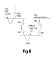
- FIG. 8 is a diagram of a network illustrating the adjustment of cycle masters by a BRAN bridge
- FIG. 9 a is a diagram of a network illustrating resource reservation for an isochronous transmission in case of a non-overlaid connection
- FIG. 9 b is a diagram of a network illustrating resource reservation for an isochronous transmission in case of an overlaid connection
- FIG. 10 is a diagram of a network illustrating the modification of a wireless bandwidth reservation by bridges on the path between a talker node and a listener node according to a variant embodiment of the invention.
- the present embodiment concerns a network formed of a plurality of IEEE 1394 wired busses. More information concerning these busses as such can be found in the following documents:
- Document (c) defines in particular the creation of isochronous connections.
- the wireless links used to link wired busses are based on the ETSI BRAN Hiperlan 2 draft standard, and in particular on document (e) ‘Broadband Radio Access Networks (BRAN); HIPERLAN Type 2; Packet based convergence layer; Part 3: IEEE 1394 Service Specific Convergence Sublayer (SSCS), version 0.g of June 2000.
- BRAN Broadband Radio Access Networks
- HIPERLAN Type 2 Packet based convergence layer
- Part 3 IEEE 1394 Service Specific Convergence Sublayer (SSCS), version 0.g of June 2000.
- SSCS Service Specific Convergence Sublayer
- ETSI is also working on the standardization of an IEEE 1394 Bridge Specific Functions sublayer:
- BRAN Broadband Radio Access Networks
- HIPERLAN Type 2 Technical Specification Packet based Convergence Layer, Part 4: IEEE 1394 Bridge Specific Functions sub-layer, version 0.g (February 2001).
- FIG. 1 represents a network formed of two IEEE 1394 device clusters 1 and 2 , each comprising a wired IEEE 1394 bus, a plurality of devices (respectively nodes 3 , 4 and 5 , 6 ) and a portal (for each bus, respectively 7 and 8 ) to the wireless Hiperlan 2 link these portals being referred to as ‘wireless boxes’ or simply ‘Wboxes’).
- the nodes are pure IEEE 1394 devices. They are not aware whether they communicate with nodes on their cluster or on the remote cluster, through the wireless link. As far as the nodes are concerned, all nodes seem to be on the same cluster. The nodes need not be aware of the wireless point to point link existing between the two clusters. The transparency of the wireless link, as far as the IEEE 1394 nodes are concerned, is made possible by the wireless boxes 7 and 8 .
- the wireless boxes 7 and 8 are not transparent to the other devices, in the sense that they are also considered to be devices on their respective busses, i.e. they are attributed a physical identifier after a bus reset.
- Each node comprises an IEEE 1394 software stack, i.e. the physical layer, the link layer and the transaction layer, as well as an application layer.
- Each wireless box also comprises these layers on their wired bus interface, with the differences which will be explained below.
- WBox 1 and WBox 2 communicate using the Hiperlan 2 protocol stack as defined in the document ETSI BRAN IEEE 1394 SSCS document (document(e)) mentioned earlier.
- a unified transaction consists in a request from one device and a response from a receiver device, in which the response is contained in the acknowledgment of the receiver device.
- Whether a transaction is unified or not i.e. ‘split’) can be determined by the receiving node, depending on its capability to respond quickly to the request of the sending node.
- the responding node transmits an acknowledgment of receipt which informs the sending node that the transaction is ‘pending’, and that the response will be sent later on.
- the sending node waits for a predetermined maximum amount of time (‘split timeout’), and abandons the request if no response has been received.
- the number of wireless links between any two nodes of the network is limited to a maximum number, in the present case to two.
- This maximum number of links is chosen in such a way that the split timeout delay of a sending device will normally suffice to cover the combined delays of the wireless links to be crossed, since each wireless link introduces an additional transmission delay between two nodes.
- the networks which will be described in relation with the figures respect this constraint: each network will comprise a maximum of one branch bus.
- a branch bus is defined as a bus linked to at least two other busses through respective wireless links. These other busses are then necessarily leaf busses, which are defined as being connected to a maximum of one other bus through a wireless link.
- the total number of devices in the network is limited by the maximum number of devices allowed by a single bus, since the goal is to have the network behave as a single bus, as far as the nodes other than the wireless boxes are concerned. In the case of the IEEE 1394, this number is equal to 64. This includes the wireless boxes, which are considered as nodes according to the present embodiment.
- FIG. 2 An example of a network is given by FIG. 2 .
- a branch bus (or cluster) 9 is connected to three leaf busses (or clusters) 10 , 11 and 12 through wireless connections respectively formed by pairs of wireless boxes.
- Wireless boxes which are root on their bus (or cluster) in the sense of document (a) are marked by an ‘R’. How roots are chosen will be explained in relation with the association process of a wireless box to an already existing network.
- each wireless box implements a register called ‘BUS_TYPE’ register.
- This register conforms to document (d). In particular, it is located at a known offset in each wireless boxes' directory.
- the register is used to store information regarding the type of the bus the wireless box is connected to (blank, leaf or branch) and regarding the existence of a branch bus in the network.
- Table 2 gives the values of the ‘bus_type’ field in the ‘BUS_TYPE’ register.
- Table 3 gives the values of the ‘branch_existence’ field in the ‘BUS_TYPE’ register.
- a blank bus is defined as being a bus which is not linked to another bus through a wireless link.
- a bus may comprise a wireless box, but this wireless box has not yet associated with a peer box on another bus.
- a wireless box is said to be associated when it has performed its Hiperlan 2 Radio Link Control association. Two busses are considered to be linked through two associated peer wireless boxes when these two boxes have checked that this link would result in an authorized network topology and configured themselves and their respective local busses accordingly.
- each wireless box on the bus is bus identification. This task consists for each wireless box in determining whether the bus is a blank bus, a leaf bus or a branch bus, given the modified topology. At this stage, a wireless box newly connected to a wired bus is not associated with any peer wireless box.
- Each node receives the identifiers of other nodes during the IEEE 1394 self-identification process, which enables each node to send a so-called ‘self_id packet’ containing, among other information, the physical identifier of the node.
- wireless boxes generate self_id packets for themselves, as well as for remote nodes—if any—on the side of their peer wireless box in case a link has been established with another bus.
- the information concerning remote nodes is known from previous resets.
- the wireless box reconstructs the topology of the network using an appropriate method.
- a method is described for example in a patent application filed by THOMSON multimedia with the French patent office on May 26, 1998 under the filing number 9806624 and having the publication number FR2779301. This method, or that described in Annex E.3.4.
- ‘Topology construction’ of document (a) also enables wireless boxes to determine the topology of the network on the side of their peer wireless boxes. This information is used to properly propagate self_id packets. Topology information comprises the list of devices on a bus or network, and a description of the way these devices are connected.
- the wireless box checks which nodes are wireless nodes, by verifying which nodes contain the bus type register, and which do not. An active wireless link is recognized when two wireless boxes appear consecutively in the topology map.
- the newly connected wireless box then updates its own BUS_TYPE register contents as follows:
- the local bus is a blank bus.
- the wireless box sets the bus_type field of the BUS_TYPE register to the value corresponding to blank.
- a wireless box detects a single wireless box on the bus which links the local bus to a remote bus (i.e. there is an active link), then the bus is a leaf bus.
- the wireless box copies the content of the ‘branch_existence’ field of the other wireless box part of a link into the corresponding field of its own BUS_TYPE register and sets the ‘bus_type’ field to leaf.
- the wireless box determines whether a branch exists through an analysis of the network topology, instead of reading the ‘branch existence’ field of another wireless box.
- Wireless boxes which were present on the bus before the bus reset can distinguish between newly connected or removed nodes and nodes which were already present before the reset, by comparing the topology maps before and after the reset.
- the bus type is not changed until it has associated with its peer wireless box and bus linking has taken place. If a wireless box detects that another wireless box has been removed, then it updates its bus_type field following the bus reset and its topology map analysis.
- FIG. 3 illustrates two clusters before association.
- Cluster 1 comprises a wireless box called ‘wbox 1 ’ and five other nodes.
- Cluster 2 comprises the peer wireless box called ‘wbox 2 ’ and three other nodes.
- the numbers indicated near the nodes are the physical identifiers attributed during the previous bus resets. Both busses are blank busses before the association of the wireless boxes and linking of the busses.
- the node with the physical identifier ‘ 5 ’ of cluster 1 is root on its bus, since it has the highest physical id number.
- a wireless box Once a wireless box has been connected to a bus and once the bus reset has been carried out, it will try to associate with a peer wireless box.
- a wireless box knows in advance an identifier of its peer with which it is to form a link. In this case, the wireless boxes know the unique ‘EUI-64’ identifier of their peer.
- the wireless box reads the EUI-64 identifiers of the other devices on its bus in order to verify whether its peer is also connected to the same bus. In this case, no association is possible in order to avoid reset loops. A corresponding message may be sent to the user, and the association procedure is aborted. As soon as a wireless box detects that its peer has been removed from the bus, it will try to associate again.
- the wireless box reads the EUI-64 identifiers of devices not only on its bus, but on all busses on its side of the network.
- the two wireless boxes associate according to the Hiperlan 2 Radio Link Control layer.
- the next step is to determine if one or both wireless boxes of an associated pair are to be the root on their respective busses. At least one wireless box of an associated pair should be root (in the sense of document (a)) on its bus, so that the reset message transmission among busses can be properly carried out. There cannot be more than one root per bus.
- ‘wbox 2 ’ is a root.
- the ‘wbox 1 ’ can be a root, but does not have to be. If both wireless boxes are root on their respective busses, then one of the pair is selected to be the dominant root (‘global root’). This root would be ‘wbox 1 ’, not ‘wbox 2 ’.
- a third bus is to be linked to a network comprising already two buses (i.e. a branch bus will exist in the final network) then at least one of the wireless boxes linking the third bus to the network should be a root.
- the branch bus will necessarily be the bus to which the third bus will be linked.
- the wireless box of the third bus shall try to become root. Its peer wireless box on the branch bus should also try to become root, to maximize the probability that at least one of the two wireless boxes becomes root.
- a wireless box may become root by using the ‘Force Root Flag’ described at section 4.1.1.1 ‘Set Force Root’ of the IEEE 1394 standard (document (a)).
- the two wireless boxes determine whether linking their busses will result in a valid network topology or not.
- the busses can be linked.
- the blank bus becomes a leaf bus and the BUS_TYPE register of the corresponding wireless box is updated accordingly.
- the former leaf bus to which the new bus is linked becomes a branch bus, and the BUS_TYPE register is also updated.
- the wireless boxes remain associated in the sense of Hiperlan 2, but do not update their BUS_TYPE registers. After each bus reset, the wireless boxes shall restart root selection and try to link their respective busses again, since a reset may be indicative of a change of the network topology.
- each wireless box sends a bus reset message to its peer wireless box.
- This message contains the complete self_id packets of the respective local bus (e.g. wbox 1 of FIG. 3 sends the self_id packets of the five nodes on cluster 1 as well as its own packet and wbox 2 sends the three self_d packets of the three nodes of cluster 2 as well as its own self_id packet) and of any busses linked with the local bus.
- each wireless box then proceeds with generating a reset on its local bus.
- each portal sends, in addition to its own self_id packets, the self_id packets received from its peer wireless box, when it is given the occasion to do so by the root node of its local bus.
- the sending of the self_id packets on each cluster takes into account the rules defined by document (a) at section E.3.3., i.e. bus grant for sending a self_id packet is given to a node's children from the left-most (lowest number) port to the right-most (highest number) port.
- wbox 2 is considered to be the root node of cluster 2 . It thus has control over when to send self_id packets for the cluster 1 nodes and when to give the possibility to one of the nodes of cluster 2 to send its own self_id packet.
- Wbox 2 receives six self_id packets from wbox 1 , and from this information deduces the topology map of cluster 1 , i.e. the connections of nodes to other nodes' ports on cluster 1 . Wbox 2 thus knows when it would be granted its turn to send a self_id packet by the root node of cluster 1 if wbox 2 were considered as directly connected as the left-most child of wbox 1 .
- Wbox 2 thus knows that it should send first on cluster 2 the self_id packets of the two left-most children of the root node of cluster 1 —which will receive the physical identifiers 0 and 1 , before beginning to grant the bus to its own children, which will receive the subsequent physical identifiers 2 , 3 and 4 .
- wbox 2 attributes to itself the following physical identifier, being the root on its bus. It thus receives the physical identifier 5 .
- Wbox 2 then proceeds with forwarding, in the correct order considering the topology and the self identification process rules, the self identification packets of wbox 1 , followed by those of the two nodes between wbox 1 and the root node of cluster 1 , and lastly the self_id packet of the root node of cluster 1 itself, which receives the highest physical identifier, i.e. 9 .
- Wbox 2 thus simulates the sending of self_id packets on cluster 2 , as if it were directly connected to cluster 1 .
- Wbox 1 When Wbox 1 is granted the bus by the root node of cluster 1 , it acts as if all nodes on cluster 2 were its children and accordingly forwards the self_id packets previously received from wbox 2 , according to the topology of cluster 2 as deduced from those same self_id packets.
- the wireless box sends a corresponding acknowledgment to its peer wireless box.
- the acknowledgment message may contain the same information as the bus-reset message, but may also be a simpler acknowledgement.
- FIG. 4 shows the self_ids of the nodes of FIG. 3 after the reset procedure.
- Every bus reset detected by a wireless box on its local bus is transmitted to its peer wireless box.
- the receiving wireless box acknowledges the bus-reset message, once the reset has been carried out.
- This acknowledgment which is the same as that mentioned previously, is normally not carried out over a wired medium, but may be necessary for a wireless medium, which is not as reliable.
- a wireless box When sending a bus reset message to its peer wireless box, a wireless box handles asynchronous data received from its peer wireless box as follows:
- wbox 1 sends a bus reset message to its peer wireless box.
- WBox 2 then performs a bus reset on cluster 2 , in a manner similar to what has already been described, using the self_id packets just received from wbox 1 .
- Wbox 2 sends an acknowledgment to wbox 1 . From that moment on, wbox 1 accepts again asynchronous data from wbox 2 (‘user data traffic’).
- wbox 2 If wbox 2 received a reset on its local bus before sending the acknowledgment, indicating a change of topology of cluster 2 , then wbox 2 in turn generates a bus reset message incorporating the new self_id packets and sends it to wbox 1 , in order to update the view which nodes of cluster 1 have of cluster 2 .
- FIGS. 4 and 5 illustrate a same network before and after a reset procedure. It is supposed that a reset is generated by the removal of the node having the physical identifier 4 on FIG. 4 .
- a reset is first performed on the leaf bus, followed by the wireless box of the leaf bus sending a bus reset message to its peer, located on the branch bus.
- the reset on the branch bus is then performed, and an acknowledgment of receipt sent to the initiating wireless box of the leaf bus.
- the wireless boxes of the branch bus then forward a bus reset message to the remaining leaf busses. Once these resets are carried out, corresponding acknowledgment messages are sent to the branch bus.
- FIG. 7 A bus reset message is forwarded by each wireless box of the branch bus to the respective peer wireless box of the leaf busses. A reset is then performed on these busses, and an acknowledgment sent back to the wireless boxes of the branch busses.
- wireless boxes receiving a bus reset message acknowledge this message to their peer wireless boxes once the reset has been performed on their local bus.
- Document (b) defines a maximum delay for a bus reset procedure. This timeout delay should be respected, according to the present embodiment.
- a first step the clock transmission on the network of busses will be discussed.
- a second step the reservation of isochronous resources on the network will be described.
- a node acts as a local cycle master, as defined by document (a).
- the role of a cycle master is to transmit the periodical cycle start packet, which is sent every 125 ⁇ s and on which all other nodes of a bus synchronize to access the bus.
- a mechanism has been defined at the level of each bus to permit propagation of a clock through the network of bridges and busses.
- An example of such a mechanism is the ‘clock adjustment’ mechanism defined at section 6.2. ‘Cycle master adjustment packet’ of document (f).
- the cycle master of a wired bus may be adjusted by any node of the wired bus using a ‘clock adjustment’ message.
- the adjusting node may in particular be a portal node which receives clock information from its peer portal node connected to another wired bus.
- a portal node need not necessarily be the cycle master of its bus in order for a clock to be propagated from a single master clock through a multi-bus network.
- the adjustment mechanism is used only on wired busses.
- Bridges be it wireless bridges or other types of bridges, have their own methods for propagating the clock between their portals. For example, in case of an ETSI BRAN Hiperlan 2 bridge, the transmission of a clock over a wireless link can be made using the mechanism described at section 5.3 ‘Cycle Synchronization Service’ in document (e). On their wired bus interface, portals will use the adjustment mechanism.
- each wired bus of the network comprises a cycle master according to document (a).
- one of the cycle masters is elected to be the network cycle master, also called ‘global’ cycle master, which will act as the cycle master of the network comprising all wired busses (clusters) and wireless links.
- the global cycle master is the cycle master of the cluster that contains the global root of the network.
- the global cycle master's clock is used to synchronize the other cycle masters, and its location defines—apart in the special case seen below—the direction of the transmission path of the clock between wireless boxes.
- a wireless box on a wired bus checks whether its bus contains the global cycle master by checking whether the global root is on the local cluster. If this is the case, the wireless box transmits clock synchronization information to its peer wireless box using, in the case of the present embodiment, the cycle synchronization service defined in document (e). The transmitting wireless box adequately configures its peer wireless box. The wireless box receiving clock information from its peer then proceeds to adjust the cycle masters of its local bus, if it is not itself the cycle master on its bus. When a wireless box receiving the clock from its peer box is at the same time cycle master, it still sends adjustment packets (which are broadcast packets) in order to conform to the procedure of the next paragraph.
- Wireless boxes also listen to clock adjustment packets sent by other nodes on their local wired bus.
- Clock adjustment packets are broadcast packets, i.e. not addressed to a specific node on a bus. If a wireless box detects such a packet on its bus, it knows that the cycle master of its bus is being adjusted. In this case, it will become a sender of clock synchronization information to its peer wireless box. Note that the clock synchronization information is derived by the wireless box from the adjusted local cycle master's cycle start, not from the clock adjustment packet used to adjust this cycle master.
- the clock coming from the global cycle master is thus propagated through the entire network (‘network’ being taken here as the group of busses linked according to the present embodiment so as to simulate a single bus).
- the process is different when a Hiperlan 2 bridge as defined in document (g) is connected to one of the wired busses and transmits clock adjustment packets on this bus, which does not necessarily contain the global cycle master.
- a mechanism is provided to transmit the clock information from the Hiperlan 2 bridge to the global cycle master, which is not directly adjusted by the bridge's portal, but by a wireless box of the global cycle master's local bus.
- the direction of transmission of clock information is different, and does not always radiate from the global cycle master.
- FIG. 8 illustrates such a case.
- the arrows indicate the direction of propagation of clock information.
- the Hiperlan 2 bridge adjusts the cycle master CM 1 of its local bus.
- the wireless box WB 1 detects the clock adjustment packets broadcast by the bridge's portal, and uses the IEEE 1394 service specific convergence layer to transmit clock synchronization information derived from CM 1 's cycle start to wireless box WB 2 .
- This wireless box adjusts the global cycle master's (CM 2 ) clock.
- WB 3 detects the adjustment packets and derives its clock synchronization information from the global cycle master's cycle start.
- WB 3 synchronizes WB 4 , which is cycle master on its own bus, and does not send any adjustment packets.
- Each wireless box determines whether it receives clock adjustment packets on its local bus. The one wireless box which does receive such packets will be the clock synchronization sender, the other the clock synchronization receiver. If no adjustment packet is detected, the clock synchronization information will be sent from the bus containing the global cycle master.
- the global cycle master detects clock adjustment packets being broadcast on its local bus, it acts as a normal cycle master: the global cycle master relinquishes its prerogatives to the Hiperlan 2 bridge.
- a cluster When a cluster is connected to a branch bus, it is the receiver of the clock. If the new cluster contains a bridge, the direction of clock propagation is reversed.
- the branch bus' cycle master becomes the sender of the clock.
- the isochronous resource manager (or ‘IRM’ as defined by document (a)) can be located in any IRM capable node.
- a wireless box When a wireless box receives a lock request on an input or output plug control register (i/oPCR) from a controller to a node on the other side of the wireless link, it keeps a copy of the request and sends the request to its peer.
- i/oPCR input or output plug control register
- a wireless box When a wireless box receives a lock response in an i/oPCR from its peer box, it checks whether it has a copy of a request with the same channel number and if yes, whether the lock succeeded.
- the wireless boxes may perform actions, which are going to be described now.
- the wireless boxes have to check whether the listener node and the talker node are on the same side of the wireless link or on different sides. In case both are one the same side, no reservation of wireless isochronous resources is required. In case the nodes are on different sides, such a reservation is required.
- the wireless box opens a wireless connection as defined by document (e). If there is enough bandwidth available, all the required bandwidth is reserved.
- only two isochronous wireless channels may be reserved over a wireless link. If both isochronous wireless channels are already reserved, no reservation can be performed. The talker and the listener are not made aware of it, and their connection remains pending. The listener won't receive any data.
- the maximum number of isochronous wireless channels may be different, or even unlimited.
- wireless boxes may reallocate the channel and/or bandwidth for one of the reserved and pending connections.
- the wireless boxes process both lock requests and lock responses. According to a preferred embodiment, only lock responses need to be processed, since they implicitly contain the corresponding lock requests.
- the latter implement a specific register.
- Table 4 gives the contents of the register implemented in the wireless boxes for each connection requiring reservation of wireless isochronous resources which is set up over the wireless link.
- This register is called the wireless plug control register, or ‘wPCR’.
- wPCR wireless plug control register
- Content of the wPCR register is similar to that of an oPCR register as defined in document (c), but it contains an additional field called ‘Direction’, which indicates whether the talker of the connection is located on the wireless box cluster, or on the side of its peer wireless box. It thus also defines the direction of the data transmission over the wireless link.
- Direction an additional field called ‘Direction’, which indicates whether the talker of the connection is located on the wireless box cluster, or on the side of its peer wireless box. It thus also defines the direction of the data transmission over the wireless link.
- the ‘point to point connection counter’ is set to one when a wireless connection is established between the talker and the listener. This field is incremented each time the connection is overlaid with a new listener which is not on the same cluster as the talker. The field is decremented each time a connection is released.
- Both wireless boxes of a pair maintain a list of connections (in the sense of Hiperlan 2) which are active on the wireless link.
- An entry into the list is composed of the talker node identifier and a pointer to the corresponding wireless PCR register.
- non-overlaid it is meant that no wireless link exists for the isochronous channel which has been reserved by the 1394 controller.
- FIG. 9 a is a diagram of a network comprising several wired busses.
- Node A is the talker node, while node B is the listener node.
- Wireless box A is connected to the bus of node A, while wireless box B is connected to the bus of node B. In the present case, only one wireless connection needs to be reserved.
- Wireless box C is connected to the same bus as wireless box B, but is not on the path between the listener and the talker nodes.
- the 1394 controller can be on any of the busses.
- talker node A and a listener node B are set by the 1394 controller mentioned earlier, through appropriate lock request messages.
- the 1394 controller performs a lock request on the input Plug Control Register (iPCR) of the listener node and a lock request on the output Plug Control Register (oPCR) of the talker node. Since these messages are transmitted to all busses, wireless boxes A, B and C (as well as all other wireless boxes) receive these requests and store their parameters, in particular the IEEE 1394 isochronous channel number. Talker node A and listener node B both send responses to the respective lock request. These responses are analyzed by the wireless boxes.
- a wireless box When a wireless box receives an iPCR lock response from the listener node through its peer wireless box, it deduces that the listener node is on the side of its peer wireless box. It will thus only need to make a reservation if it finds that the talker node is on its own side.
- the wireless box is certain that the talker is not on its side of the network if it also receives the oPCR with the same channel number from its peer box. In this case, no reservation of wireless resources is made.
- the wireless box is certain that the talker is on its side of the bus when it detects an oPCR register in any node, the oPCR register bearing the same channel number.
- the wireless box carries out a process which consists in reading oPCR registers of nodes on its side of the network, both on the local cluster and remote clusters, looking for the appropriate channel number.
- the wireless box makes the necessary isochronous resource reservations.
- the wireless box also maintains a point to point connection counter, similar to the counter in the iPCR and oPCR registers, as defined in document (c) and sets this point to point connection counter to ‘1’.
- a wireless box When a wireless box receives an oPCR lock response from the talker node through its peer wireless box, it deduces that the talker node is on the side of its peer wireless box. It will thus only need to make a reservation if it finds that the listener node is on its own side.
- the wireless box is certain that the listener node is not on its side of the network if it also receives the iPCR with the same channel number from its peer box. In this case, no reservation of wireless resources is made.
- the wireless box is certain that the listener node is on its side of the bus when it detects an iPCR register in any node on its side of the network, the iPCR register bearing the same channel number as that in the oPCR.
- the wireless box carries out a process which consists in reading iPCR registers of nodes on its side of the network, looking for the appropriate channel number.
- the wireless box makes the necessary isochronous resource reservations, and sets its point to point connection counter and that of its peer wireless box to ‘1’.
- wireless box B receives an oPCR lock response through wireless box A from talker node A. It will also receive an iPCR lock response on its local bus from listener node B.
- Overlaying a connection onto an existing connection consists in adding a listener to the existing connection.
- the oPCR register of the talker node and the iPCR register of the new listener node are modified: the point to point connection counters are incremented in each register, and the isochronous channel number is copied from the oPCR into the iPCR of the new listener. If the listener and the talker are on different clusters, the lock request is sent, as for the initial point to point connection, across the wireless link.
- the overlaid listener may be one of the existing listeners.
- the point to point connection counter of the o/iPCR is incremented, and the point to point connection counter of the wPCR register is also incremented.
- FIG. 9 b illustrates the wireless connections requiring reservation for a particular configuration of a network in case of an overlaid connection.
- An isochronous channel has been set up between devices A and B.
- To overlay a connection between A and C one additional connection is required in addition to the two which already exist.
- a wireless box When a wireless box receives a lock response from its peer for the oPCR of the talker node and the talker is unconnected, this being detected by checking whether the point to point connection counter of the corresponding wPCR register is 0, a wireless connection is no longer necessary, and the corresponding resources can be deallocated by the wireless box by sending an appropriate message to its access point.
- a wireless box periodically reads the bandwidth written in the oPCR register of the talker nodes for which is has listed an active connection and which are on its cluster. If the bandwidth has been modified compared to resources requested on the wireless link, the wireless box modifies the bandwidth reservation on the wireless link.
- each wireless box periodically polls the output plug registers of talker nodes on its own side of the network and for which it participates in the connection, and does not limit this polling to talker nodes on its local wired bus. If the bandwidth indicated in one of the output plug registers of these talker nodes differs from the bandwidth reserved on the wireless link, the wireless box attempts to modify the reserved wireless bandwidth value correspondingly.
- FIG. 10 gives an illustration of the process. Although the illustrated connection links one talker node (identified by its output plug register oPCR) to one listener node (identified by its input plug register iPCR), the connection may comprise additional listener nodes.
- the talker node and the listener node are located on different leaf busses, both leaf busses being connected to a central branch bus.
- Two wireless devices list the talker node as being on their side of the network. They consequently periodically query the talker node's output plug register. Note that the query message from WB 3 crosses the bridge formed by WB 1 and WB 2 . Each wireless box then updates resource reservations only for its respective bridge, if necessary.
- a broadcast-out connection is a connection of a talker node to a broadcast channel
- a broadcast-in connection is a connection of a listener node to a broadcast channel
- An application establishing a broadcast-out connection does in general not know whether the output plug will continue to transmit an isochronous data flow or not.
- An application establishing a broadcast-in connection does in general not know whether there is an output plug transmitting an isochronous data flow over the broadcast channel defined in the broadcast connection, and whether, if such an output plug exists, this output plug will continue transmitting or not.
- Wireless boxes monitor the network to detect whether bridges are to take part in broadcast connections.
- Each wireless box reads, for example periodically, the output plug registers of nodes on its side of the network and tests the broadcast connection counters of these registers. If a broadcast connection counter is set, the wireless box forwards the corresponding node identifier and channel number to its peer wireless box, which polls the input plug registers of nodes on its own side to detect the existence of a broadcast-in connection having same channel number. If such a broadcast-in connection is detected, an isochronous channel is opened over the wireless link, for example by the wireless box on the side of the broadcast-in node.
- a wireless PCR is created for the broadcast connection, according to the rules already described.
- a wireless box For a broadcast connection for which the talker node is on its side of the network, a wireless box regularly checks whether the broadcast out connection is still active by polling the corresponding output plug register of the talker node and testing the broadcast connection counter. If this flag is not set anymore, then the reserved wireless resources are released.
- a wireless box located on the broadcast-in side of the network regularly reads the iPCR of the listener node to check whether the broadcast-in connection is still active. When this is not the case, the iPCRs of all other nodes located on that side of the network are checked for the channel number corresponding to the broadcast connection. If none is found, the reserved wireless isochronous resources are released.
Abstract
-
- associating the two portals to the wireless network;
- exchanging, between the two portals of self identification packets of nodes connected to their respective local busses, including the self identification packets of the portals themselves;
- generating a reset on each bus;
- carrying out a self identification procedure on each bus, where each portal generates self identification packets for itself and for nodes of the respective remote bus, using the self identification packets received following the association step.
Description
-
- associating the two portals to the wireless network;
- exchanging, between the two portals, self identification packets of nodes connected to their respective local busses, including the self identification packets of the portals themselves;
- generating a reset on each bus;
- carrying out a self identification procedure on each bus, where each portal generates self identification packets for itself and for nodes of the respective remote bus, using the self identification packets received following the association step.
The portals linked to each communication bus (cluster) emulate the nodes on their respective cluster for the other communication bus. Nodes linked to a cluster will have visibility of the nodes on the other cluster, in addition to the portal. For this purpose, the portals generate self identification packets for the emulated nodes, in addition to their own self identification packets.
| TABLE 1 |
| indicates the contents of the ‘BUS_TYPE’ register. |
| | branch_existence | ||
| 2 | 2 | ||
| TABLE 2 | |||
| Value | Comments | ||
| 00b | Blank bus | ||
| 01b | |
||
| 10b | |
||
| 11b | Reserved | ||
| TABLE 3 | |||
| Value | Comments | ||
| 00b | Branch bus doesn't exist | ||
| 01b | Branch bus exists | ||
| 10b | Reserved | ||
| 11b | Reserved | ||
-
- At least one of the wireless boxes should be root on its bus.
- At least one of the wireless boxes should be on a blank bus. Else, the resulting network would comprise more than one branch bus, which is not authorized if the topology limitations relating to the number of wireless links between any two nodes are to be respected.
- If a wireless box is on a leaf bus, the branch_existence field of this wireless box should indicate that there is not yet any branch bus in the network (binary value ‘00’).
-
- The isochronous management follows the recommendation in document (c).
- The
IEEE 1394 node controlling the connection (‘1394 controller’ in what follows) between the talker node and the listener node cannot be distributed over two nodes. It is located on a single node. Therefore a controller can't be located on both sides of the wireless link. The 1394 controller's task is to issue the lock requests to the different talking or listening nodes.
| TABLE 4 | |||||||
| Point to | |||||||
| Broadcast | point | ||||||
| connection | connection | Channel | Data | Overhead | |||
| counter | counter | Direction | number | | ID | Payload | |
| 1 | 6 | 2 | 6 | 2 | 4 | 10 | |
Table 5 gives the values of the ‘direction’ field in the ‘wPCR’ register
| TABLE 5 | |||
| Direction | Comments | ||
| 00b | No talker | ||
| 01b | Talker is located on the cluster of the |
||
| 10b | Talker is located on the |
||
| 11b | Reserved | ||
Claims (23)
Applications Claiming Priority (13)
| Application Number | Priority Date | Filing Date | Title |
|---|---|---|---|
| EP00402908 | 2000-10-19 | ||
| EP00402908 | 2000-10-19 | ||
| EP00402901 | 2000-10-19 | ||
| EP00402901A EP1199840A1 (en) | 2000-10-19 | 2000-10-19 | Method for connecting an IEEE1394 remote device to a cluster of IEEE1394 devices through a wireless link |
| EP00402901.3 | 2000-10-19 | ||
| EP00402908.8 | 2000-10-19 | ||
| EP01400826A EP1246402A1 (en) | 2001-03-30 | 2001-03-30 | Method for linking several communication busses using wireless links |
| EP01400826 | 2001-03-30 | ||
| EP01400826.2 | 2001-03-30 | ||
| EP01114694A EP1246400A1 (en) | 2001-03-30 | 2001-06-19 | Method for linking several communication busses using wireless links |
| EP01114694.1 | 2001-06-19 | ||
| EP01114694 | 2001-06-19 | ||
| PCT/EP2001/012335 WO2002037765A1 (en) | 2000-10-19 | 2001-10-18 | Method for linking several communication busses using wireless links |
Publications (2)
| Publication Number | Publication Date |
|---|---|
| US20040057411A1 US20040057411A1 (en) | 2004-03-25 |
| US8009590B2 true US8009590B2 (en) | 2011-08-30 |
Family
ID=27440056
Family Applications (1)
| Application Number | Title | Priority Date | Filing Date |
|---|---|---|---|
| US10/399,606 Expired - Fee Related US8009590B2 (en) | 2000-10-19 | 2001-10-18 | Method for linking several communication busses using wireless links |
Country Status (7)
| Country | Link |
|---|---|
| US (1) | US8009590B2 (en) |
| EP (1) | EP1327328B1 (en) |
| AT (1) | ATE380422T1 (en) |
| AU (1) | AU2002221746A1 (en) |
| DE (1) | DE60131765T2 (en) |
| MX (1) | MXPA03003415A (en) |
| WO (1) | WO2002037765A1 (en) |
Cited By (2)
| Publication number | Priority date | Publication date | Assignee | Title |
|---|---|---|---|---|
| US20110007666A1 (en) * | 2007-10-04 | 2011-01-13 | Robby Gurdan | Digital multimedia network with parameter join mechanism |
| US9276772B2 (en) | 2010-08-20 | 2016-03-01 | Samsung Electronics Co., Ltd. | Method and apparatus for transmitting and receiving data based on secured path bandwidth in network established by using audio/video interface |
Families Citing this family (16)
| Publication number | Priority date | Publication date | Assignee | Title |
|---|---|---|---|---|
| EP1199840A1 (en) * | 2000-10-19 | 2002-04-24 | THOMSON multimedia | Method for connecting an IEEE1394 remote device to a cluster of IEEE1394 devices through a wireless link |
| EP1199839A1 (en) * | 2000-10-19 | 2002-04-24 | THOMSON multimedia | Method for making bridge aware nodes communicate over hiperlan 2 bridges |
| EP1391085B1 (en) * | 2001-05-29 | 2006-08-02 | Thomson Licensing | Method for managing a communication network comprising wireless links with more than two wireless devices |
| US6957358B1 (en) * | 2002-01-28 | 2005-10-18 | Cisco Systems, Inc. | Scaling dynamic clock distribution for large service provider networks |
| US6788650B2 (en) * | 2002-06-06 | 2004-09-07 | Motorola, Inc. | Network architecture, addressing and routing |
| JP3688664B2 (en) | 2002-07-29 | 2005-08-31 | 株式会社東芝 | Relay device and network relay method |
| EP1593236A2 (en) * | 2003-01-31 | 2005-11-09 | Koninklijke Philips Electronics N.V. | Method and bridging device for prioritizing transfer of data streams |
| US7995497B2 (en) * | 2003-02-27 | 2011-08-09 | Hewlett-Packard Development Company, L.P. | Spontaneous topology discovery in a multi-node computer system |
| FR2854016A1 (en) * | 2003-04-17 | 2004-10-22 | Thomson Licensing Sa | Reset messages transmitting method for use in communication network, involves transmitting reset messages of one bus to another other bus, when number of nodes is changed and number of nodes is not increased or decreased |
| DE102004052440B3 (en) * | 2004-10-28 | 2006-04-06 | Infineon Technologies Ag | A method for computer-aided management of a telecommunications conference and telecommunication conference servers |
| US8050624B2 (en) * | 2005-06-24 | 2011-11-01 | Rosemount, Inc. | Distributed process control system and method utilizing wireless communication of packet messages |
| KR100767109B1 (en) * | 2006-06-07 | 2007-10-17 | 삼성전자주식회사 | Method for bridging wireless bridge for wireless ieee 1394 network and the wireless bridge apparatus thereof |
| CN101179749B (en) * | 2006-11-09 | 2010-05-12 | 艾威梯科技(北京)有限公司 | System and method for supporting automatic establishment and disconnection of wireless cluster connection |
| US8116223B2 (en) | 2006-11-09 | 2012-02-14 | Ivt Technology Inc. | System and method for supporting automatic establishing and disconnecting several wireless connections |
| FR2915338A1 (en) * | 2007-04-17 | 2008-10-24 | Canon Kk | METHOD FOR TRANSMITTING AND RECEIVING DATA CONTENTS IN A COMMUNICATION NETWORK, COMPUTER PROGRAM PRODUCT, STORAGE MEDIUM AND DEVICES THEREOF |
| JP5321349B2 (en) * | 2009-08-24 | 2013-10-23 | 富士通セミコンダクター株式会社 | Data transfer method and data transfer apparatus |
Citations (19)
| Publication number | Priority date | Publication date | Assignee | Title |
|---|---|---|---|---|
| WO1999035587A1 (en) | 1997-12-30 | 1999-07-15 | Koninklijke Philips Electronics N.V. | Method and apparatus for distributing a cycle clock to a plurality of bus nodes in a bus bridge |
| WO1999055028A1 (en) | 1998-04-21 | 1999-10-28 | Thomson Multimedia | Method for synchronisation in a communication network and implementing appliances |
| WO1999055208A1 (en) | 1998-04-24 | 1999-11-04 | Nhk Spring Co., Ltd. | Curtain hanging device |
| WO1999065204A2 (en) | 1998-06-08 | 1999-12-16 | Koninklijke Philips Electronics N.V. | Wireless coupling of standardized networks and non-standardized nodes |
| FR2786355A1 (en) | 1998-11-25 | 2000-05-26 | Thomson Multimedia Sa | Home automation two bus communication system processing having two communicator buses and modelling/emulating processing portal cordless bridge/portal and finding pass band outside global register. |
| US6128318A (en) * | 1998-01-23 | 2000-10-03 | Philips Electronics North America Corporation | Method for synchronizing a cycle master node to a cycle slave node using synchronization information from an external network or sub-network which is supplied to the cycle slave node |
| WO2001056226A1 (en) | 2000-01-27 | 2001-08-02 | Thomson Licensing S.A. | Method for isochronous resource management in a network based on hiperlan 2 technology |
| US6298405B1 (en) * | 1997-02-14 | 2001-10-02 | Canon Kabushiki Kaisha | Data communication system, printing system and data communication apparatus |
| US6446142B1 (en) * | 1998-10-22 | 2002-09-03 | Sony Corporation | Method of and apparatus for dynamically binding subobjects into objects to represent functions and characteristics of a device within an IEEE 1394 serial bus network |
| US20030043771A1 (en) * | 1997-08-07 | 2003-03-06 | Akihiko Mizutani | Connection establishment method, communication method, state change transmission method, state changing method wireless apparatus, wireless device, and computer |
| US20030134590A1 (en) * | 1998-08-11 | 2003-07-17 | Hirofumi Suda | Data communication apparatus, data communication system, data communication method and storage medium |
| US6658475B1 (en) * | 1998-01-23 | 2003-12-02 | Sony Corporation | Method and device for initializing a wireless network using a plurality of controlled devices |
| US6694363B1 (en) * | 1999-06-04 | 2004-02-17 | Kabushiki Kaisha Toshiba | Network equipment and networking method |
| US6694139B1 (en) * | 1999-10-06 | 2004-02-17 | Sony Corporation | Wireless communication apparatus and method, and cable communication apparatus |
| US6885643B1 (en) * | 1999-09-30 | 2005-04-26 | Kabushiki Kaisha Toshiba | Method and device for facilitating efficient data transfer via a wireless communication network |
| US6954467B1 (en) * | 1999-09-07 | 2005-10-11 | Koninklijke Philips Electronics N.V. | Clustered networked devices |
| US7002928B1 (en) * | 2000-06-21 | 2006-02-21 | Sony Corporation | IEEE 1394-based protocol repeater |
| US7200683B1 (en) * | 1999-08-17 | 2007-04-03 | Samsung Electronics, Co., Ltd. | Device communication and control in a home network connected to an external network |
| US20070121656A1 (en) * | 2005-11-28 | 2007-05-31 | Olympus Communication Technology Of America, Inc. | Multilayer bridging system and method |
-
2001
- 2001-10-18 AT AT01993089T patent/ATE380422T1/en not_active IP Right Cessation
- 2001-10-18 WO PCT/EP2001/012335 patent/WO2002037765A1/en active IP Right Grant
- 2001-10-18 DE DE60131765T patent/DE60131765T2/en not_active Expired - Lifetime
- 2001-10-18 EP EP01993089A patent/EP1327328B1/en not_active Expired - Lifetime
- 2001-10-18 AU AU2002221746A patent/AU2002221746A1/en not_active Abandoned
- 2001-10-18 MX MXPA03003415A patent/MXPA03003415A/en active IP Right Grant
- 2001-10-18 US US10/399,606 patent/US8009590B2/en not_active Expired - Fee Related
Patent Citations (19)
| Publication number | Priority date | Publication date | Assignee | Title |
|---|---|---|---|---|
| US6298405B1 (en) * | 1997-02-14 | 2001-10-02 | Canon Kabushiki Kaisha | Data communication system, printing system and data communication apparatus |
| US20030043771A1 (en) * | 1997-08-07 | 2003-03-06 | Akihiko Mizutani | Connection establishment method, communication method, state change transmission method, state changing method wireless apparatus, wireless device, and computer |
| WO1999035587A1 (en) | 1997-12-30 | 1999-07-15 | Koninklijke Philips Electronics N.V. | Method and apparatus for distributing a cycle clock to a plurality of bus nodes in a bus bridge |
| US6128318A (en) * | 1998-01-23 | 2000-10-03 | Philips Electronics North America Corporation | Method for synchronizing a cycle master node to a cycle slave node using synchronization information from an external network or sub-network which is supplied to the cycle slave node |
| US6658475B1 (en) * | 1998-01-23 | 2003-12-02 | Sony Corporation | Method and device for initializing a wireless network using a plurality of controlled devices |
| WO1999055028A1 (en) | 1998-04-21 | 1999-10-28 | Thomson Multimedia | Method for synchronisation in a communication network and implementing appliances |
| WO1999055208A1 (en) | 1998-04-24 | 1999-11-04 | Nhk Spring Co., Ltd. | Curtain hanging device |
| WO1999065204A2 (en) | 1998-06-08 | 1999-12-16 | Koninklijke Philips Electronics N.V. | Wireless coupling of standardized networks and non-standardized nodes |
| US20030134590A1 (en) * | 1998-08-11 | 2003-07-17 | Hirofumi Suda | Data communication apparatus, data communication system, data communication method and storage medium |
| US6446142B1 (en) * | 1998-10-22 | 2002-09-03 | Sony Corporation | Method of and apparatus for dynamically binding subobjects into objects to represent functions and characteristics of a device within an IEEE 1394 serial bus network |
| FR2786355A1 (en) | 1998-11-25 | 2000-05-26 | Thomson Multimedia Sa | Home automation two bus communication system processing having two communicator buses and modelling/emulating processing portal cordless bridge/portal and finding pass band outside global register. |
| US6694363B1 (en) * | 1999-06-04 | 2004-02-17 | Kabushiki Kaisha Toshiba | Network equipment and networking method |
| US7200683B1 (en) * | 1999-08-17 | 2007-04-03 | Samsung Electronics, Co., Ltd. | Device communication and control in a home network connected to an external network |
| US6954467B1 (en) * | 1999-09-07 | 2005-10-11 | Koninklijke Philips Electronics N.V. | Clustered networked devices |
| US6885643B1 (en) * | 1999-09-30 | 2005-04-26 | Kabushiki Kaisha Toshiba | Method and device for facilitating efficient data transfer via a wireless communication network |
| US6694139B1 (en) * | 1999-10-06 | 2004-02-17 | Sony Corporation | Wireless communication apparatus and method, and cable communication apparatus |
| WO2001056226A1 (en) | 2000-01-27 | 2001-08-02 | Thomson Licensing S.A. | Method for isochronous resource management in a network based on hiperlan 2 technology |
| US7002928B1 (en) * | 2000-06-21 | 2006-02-21 | Sony Corporation | IEEE 1394-based protocol repeater |
| US20070121656A1 (en) * | 2005-11-28 | 2007-05-31 | Olympus Communication Technology Of America, Inc. | Multilayer bridging system and method |
Non-Patent Citations (1)
| Title |
|---|
| David V. James: "Hiperlan-2 wireless informative annex as submitted to the p1394.1 committee," IEEE, P1394.1 Draft Standard for High Performance Serial Bus Bridges, IEEE, New York, NY, US, Oct. 12, 1999 pp. 1-12. |
Cited By (3)
| Publication number | Priority date | Publication date | Assignee | Title |
|---|---|---|---|---|
| US20110007666A1 (en) * | 2007-10-04 | 2011-01-13 | Robby Gurdan | Digital multimedia network with parameter join mechanism |
| US8855008B2 (en) * | 2007-10-04 | 2014-10-07 | U-Man Universal Media Access Networks Gmbh | Digital multimedia network with parameter join mechanism |
| US9276772B2 (en) | 2010-08-20 | 2016-03-01 | Samsung Electronics Co., Ltd. | Method and apparatus for transmitting and receiving data based on secured path bandwidth in network established by using audio/video interface |
Also Published As
| Publication number | Publication date |
|---|---|
| DE60131765D1 (en) | 2008-01-17 |
| EP1327328A1 (en) | 2003-07-16 |
| MXPA03003415A (en) | 2003-08-07 |
| ATE380422T1 (en) | 2007-12-15 |
| US20040057411A1 (en) | 2004-03-25 |
| AU2002221746A1 (en) | 2002-05-15 |
| DE60131765T2 (en) | 2008-11-20 |
| WO2002037765A1 (en) | 2002-05-10 |
| EP1327328B1 (en) | 2007-12-05 |
Similar Documents
| Publication | Publication Date | Title |
|---|---|---|
| US8009590B2 (en) | Method for linking several communication busses using wireless links | |
| JP4689130B2 (en) | Isochronous resource management method in a network based on HIPERLAN type 2 | |
| US7433341B2 (en) | Method for connecting an IEEE1394 remote device to a cluster of IEEE1394 devices through a wireless link | |
| US6754184B2 (en) | Information processing apparatus and method, and distribution medium | |
| US6539450B1 (en) | Method and system for adjusting isochronous bandwidths on a bus | |
| US8005021B2 (en) | Method and device for address allocation for transmitting packets over a transparent bridge | |
| WO2001047240A2 (en) | Method and system for adjusting isochronous bandwidths on a bus | |
| CN1321512C (en) | Method for managing communication network comprising wireless links with more than two wireless devices | |
| EP1472832B1 (en) | Method and device for managing a connection and resource reservation in a communication network comprising a bridge | |
| US6584539B1 (en) | Method and system for message broadcast flow control on a bus bridge interconnect | |
| KR100828064B1 (en) | Method for reserving isochronous resources in a network comprising a wireless link | |
| EP1246400A1 (en) | Method for linking several communication busses using wireless links | |
| JP4336536B2 (en) | Transmission speed setting device, transmission speed setting method, information transmission system, transmission speed setting program, and information recording medium | |
| EP1246402A1 (en) | Method for linking several communication busses using wireless links | |
| WO2001038996A9 (en) | Method and system for adjusting isochronous bandwidths on a bus | |
| JP4611974B2 (en) | Method for transferring an IEEE 1394 bus reinitialization message and apparatus for performing such a method | |
| EP1775889A1 (en) | Bridge and transmission device, and information system | |
| JPH11215132A (en) | Device and method for processing information and distribution medium |
Legal Events
| Date | Code | Title | Description |
|---|---|---|---|
| AS | Assignment |
Owner name: THOMSON LICENSING S.A., FRANCE Free format text: ASSIGNMENT OF ASSIGNORS INTEREST;ASSIGNORS:PERROT, SEBASTIEN;VINCENT, CHRISTOPHE;STRAUB, GILLES;AND OTHERS;REEL/FRAME:014366/0316 Effective date: 20011023 |
|
| AS | Assignment |
Owner name: THOMSON LICENSING,FRANCE Free format text: ASSIGNMENT OF ASSIGNORS INTEREST;ASSIGNOR:THOMSON LICENSING S.A.;REEL/FRAME:024232/0031 Effective date: 20100405 Owner name: THOMSON LICENSING, FRANCE Free format text: ASSIGNMENT OF ASSIGNORS INTEREST;ASSIGNOR:THOMSON LICENSING S.A.;REEL/FRAME:024232/0031 Effective date: 20100405 |
|
| ZAAA | Notice of allowance and fees due |
Free format text: ORIGINAL CODE: NOA |
|
| ZAAB | Notice of allowance mailed |
Free format text: ORIGINAL CODE: MN/=. |
|
| STCF | Information on status: patent grant |
Free format text: PATENTED CASE |
|
| FPAY | Fee payment |
Year of fee payment: 4 |
|
| AS | Assignment |
Owner name: INTERDIGITAL CE PATENT HOLDINGS, FRANCE Free format text: ASSIGNMENT OF ASSIGNORS INTEREST;ASSIGNOR:THOMSON LICENSING;REEL/FRAME:047332/0511 Effective date: 20180730 |
|
| MAFP | Maintenance fee payment |
Free format text: PAYMENT OF MAINTENANCE FEE, 8TH YEAR, LARGE ENTITY (ORIGINAL EVENT CODE: M1552); ENTITY STATUS OF PATENT OWNER: LARGE ENTITY Year of fee payment: 8 |
|
| FEPP | Fee payment procedure |
Free format text: MAINTENANCE FEE REMINDER MAILED (ORIGINAL EVENT CODE: REM.); ENTITY STATUS OF PATENT OWNER: LARGE ENTITY |
|
| LAPS | Lapse for failure to pay maintenance fees |
Free format text: PATENT EXPIRED FOR FAILURE TO PAY MAINTENANCE FEES (ORIGINAL EVENT CODE: EXP.); ENTITY STATUS OF PATENT OWNER: LARGE ENTITY |
|
| STCH | Information on status: patent discontinuation |
Free format text: PATENT EXPIRED DUE TO NONPAYMENT OF MAINTENANCE FEES UNDER 37 CFR 1.362 |
|
| FP | Lapsed due to failure to pay maintenance fee |
Effective date: 20230830 |
|
| AS | Assignment |
Owner name: INTERDIGITAL CE PATENT HOLDINGS, SAS, FRANCE Free format text: CORRECTIVE ASSIGNMENT TO CORRECT THE RECEIVING PARTY NAME FROM INTERDIGITAL CE PATENT HOLDINGS TO INTERDIGITAL CE PATENT HOLDINGS, SAS. PREVIOUSLY RECORDED AT REEL: 47332 FRAME: 511. ASSIGNOR(S) HEREBY CONFIRMS THE ASSIGNMENT;ASSIGNOR:THOMSON LICENSING;REEL/FRAME:066703/0509 Effective date: 20180730 |