US8009059B2 - Downhole power generation and communications apparatus and method - Google Patents
Downhole power generation and communications apparatus and method Download PDFInfo
- Publication number
- US8009059B2 US8009059B2 US10/569,707 US56970704A US8009059B2 US 8009059 B2 US8009059 B2 US 8009059B2 US 56970704 A US56970704 A US 56970704A US 8009059 B2 US8009059 B2 US 8009059B2
- Authority
- US
- United States
- Prior art keywords
- downhole
- control module
- energy
- pressure wave
- pressure
- Prior art date
- Legal status (The legal status is an assumption and is not a legal conclusion. Google has not performed a legal analysis and makes no representation as to the accuracy of the status listed.)
- Expired - Fee Related, expires
Links
- 238000000034 method Methods 0.000 title claims abstract description 47
- 238000004891 communication Methods 0.000 title description 39
- 238000010248 power generation Methods 0.000 title description 5
- 239000000463 material Substances 0.000 claims description 26
- 238000012545 processing Methods 0.000 claims description 17
- 230000005540 biological transmission Effects 0.000 claims description 14
- 239000003990 capacitor Substances 0.000 claims description 12
- 238000004146 energy storage Methods 0.000 claims description 11
- 230000003213 activating effect Effects 0.000 claims description 4
- 238000012544 monitoring process Methods 0.000 claims description 4
- 239000013078 crystal Substances 0.000 claims description 2
- 230000004913 activation Effects 0.000 claims 2
- 238000005259 measurement Methods 0.000 description 13
- 239000012530 fluid Substances 0.000 description 12
- 238000004519 manufacturing process Methods 0.000 description 11
- 238000006243 chemical reaction Methods 0.000 description 9
- 230000008859 change Effects 0.000 description 6
- 238000005553 drilling Methods 0.000 description 6
- 230000008569 process Effects 0.000 description 5
- 229930195733 hydrocarbon Natural products 0.000 description 4
- 150000002430 hydrocarbons Chemical class 0.000 description 4
- 238000011835 investigation Methods 0.000 description 4
- 230000007774 longterm Effects 0.000 description 4
- 238000009825 accumulation Methods 0.000 description 3
- 238000013461 design Methods 0.000 description 3
- 238000002955 isolation Methods 0.000 description 3
- 239000007788 liquid Substances 0.000 description 3
- 239000004215 Carbon black (E152) Substances 0.000 description 2
- 239000011149 active material Substances 0.000 description 2
- 230000004888 barrier function Effects 0.000 description 2
- 230000008901 benefit Effects 0.000 description 2
- 230000007812 deficiency Effects 0.000 description 2
- 238000010586 diagram Methods 0.000 description 2
- 230000004069 differentiation Effects 0.000 description 2
- 230000000694 effects Effects 0.000 description 2
- 239000002184 metal Substances 0.000 description 2
- 238000005086 pumping Methods 0.000 description 2
- 230000001105 regulatory effect Effects 0.000 description 2
- 229920002545 silicone oil Polymers 0.000 description 2
- 238000012546 transfer Methods 0.000 description 2
- 230000007704 transition Effects 0.000 description 2
- XLYOFNOQVPJJNP-UHFFFAOYSA-N water Substances O XLYOFNOQVPJJNP-UHFFFAOYSA-N 0.000 description 2
- 230000009471 action Effects 0.000 description 1
- 238000004458 analytical method Methods 0.000 description 1
- 238000013459 approach Methods 0.000 description 1
- 230000000712 assembly Effects 0.000 description 1
- 238000000429 assembly Methods 0.000 description 1
- 230000000740 bleeding effect Effects 0.000 description 1
- 238000009530 blood pressure measurement Methods 0.000 description 1
- 238000009529 body temperature measurement Methods 0.000 description 1
- 230000015556 catabolic process Effects 0.000 description 1
- 239000000919 ceramic Substances 0.000 description 1
- 238000010276 construction Methods 0.000 description 1
- 230000007797 corrosion Effects 0.000 description 1
- 238000005260 corrosion Methods 0.000 description 1
- 238000013016 damping Methods 0.000 description 1
- 238000006731 degradation reaction Methods 0.000 description 1
- 230000000593 degrading effect Effects 0.000 description 1
- 239000008367 deionised water Substances 0.000 description 1
- 230000005674 electromagnetic induction Effects 0.000 description 1
- 238000005516 engineering process Methods 0.000 description 1
- 230000001939 inductive effect Effects 0.000 description 1
- 238000009434 installation Methods 0.000 description 1
- 230000002045 lasting effect Effects 0.000 description 1
- 230000005415 magnetization Effects 0.000 description 1
- 238000012986 modification Methods 0.000 description 1
- 230000004048 modification Effects 0.000 description 1
- 210000002445 nipple Anatomy 0.000 description 1
- 238000011017 operating method Methods 0.000 description 1
- 230000000737 periodic effect Effects 0.000 description 1
- 238000005381 potential energy Methods 0.000 description 1
- 230000001681 protective effect Effects 0.000 description 1
- 239000010453 quartz Substances 0.000 description 1
- 230000000717 retained effect Effects 0.000 description 1
- VYPSYNLAJGMNEJ-UHFFFAOYSA-N silicon dioxide Inorganic materials O=[Si]=O VYPSYNLAJGMNEJ-UHFFFAOYSA-N 0.000 description 1
- 239000007787 solid Substances 0.000 description 1
- 230000003068 static effect Effects 0.000 description 1
- 238000012360 testing method Methods 0.000 description 1
- 238000010792 warming Methods 0.000 description 1
Images


Classifications
-
- E—FIXED CONSTRUCTIONS
- E21—EARTH DRILLING; MINING
- E21B—EARTH DRILLING, e.g. DEEP DRILLING; OBTAINING OIL, GAS, WATER, SOLUBLE OR MELTABLE MATERIALS OR A SLURRY OF MINERALS FROM WELLS
- E21B47/00—Survey of boreholes or wells
- E21B47/12—Means for transmitting measuring-signals or control signals from the well to the surface, or from the surface to the well, e.g. for logging while drilling
- E21B47/14—Means for transmitting measuring-signals or control signals from the well to the surface, or from the surface to the well, e.g. for logging while drilling using acoustic waves
-
- E—FIXED CONSTRUCTIONS
- E21—EARTH DRILLING; MINING
- E21B—EARTH DRILLING, e.g. DEEP DRILLING; OBTAINING OIL, GAS, WATER, SOLUBLE OR MELTABLE MATERIALS OR A SLURRY OF MINERALS FROM WELLS
- E21B41/00—Equipment or details not covered by groups E21B15/00 - E21B40/00
- E21B41/0085—Adaptations of electric power generating means for use in boreholes
Definitions
- the present invention generally relates to communications with the long-term placement of downhole completions equipment. More particularly, the present invention relates to an apparatus and method to wirelessly communicate with downhole completions equipment. More particularly still, the present invention relates to methods and apparatuses to wirelessly communicate with and generate power for downhole completions equipment, particularly those permanently installed in the well.
- Completion generally refers to the process by which a drilled wellbore is “completed” or prepared to produce hydrocarbons therethrough.
- the completions process follows drilling, casing, and perforating operations undertaken to reach the subterranean reservoir.
- completions usually involve the installation of at least one string of production tubing, various packer assemblies, and other downhole tools (such as valves, nipples, and pumps).
- the packers serve to isolate one or more production zones from other portions of the wellbore depth while the production tubing serves as a conduit to carry the hydrocarbons from the isolated zone to the surface.
- smart completions generally refers to the placement of downhole measurement devices, usually temperature and pressure sensors, to monitor the production of the reservoir.
- the data from the smart completions equipment is evaluated at the surface so that decisions can be made regarding production methods and techniques in order to maximize the lifetime and productivity of the well.
- completions equipment is expected to last the entire life of the well, smart completions systems capable of lasting upwards of 15 years are necessary. Therefore, systems that rely on batteries or other stored power devices are generally not sufficient for the life of smart or other permanent completions systems.
- the monitoring of smart or permanent completions equipment is periodic in nature but this is subject to change as more detailed and complex measurements are enabled. Therefore, there is a long-felt need in the industry for a long-term, permanent, communication system for smart or permanent completions devices.
- a digital communication one typically consisting of strings of 0 s and 1 s, is more reliably read and verified on the surface than it's analog counterpart.
- advanced electronics those capable of turning the analog temperature and pressure measurements into digital data streams, are needed.
- a system to deliver power to downhole completions equipment is also highly desirable. Most desirable of all is a system to perform digital communications and transfer power between downhole sensors and surface equipment.
- MWD Measurement While Drilling
- the apparatus preferably includes a surface unit including a pressure wave generator and a signal processing unit.
- the apparatus also preferably includes a downhole energy converter configured to convert pressure fluctuations from the pressure wave generator to electrical energy.
- the apparatus also preferably includes an energy storage device configured to store electrical energy from said energy converter.
- the apparatus also preferably includes a control module configured to receive data from the downhole sensor and to transmit the data to the signal processing unit through a pressure wave telemetry unit.
- the deficiencies of the prior art can also be addressed by a method to communicate with a downhole sensor.
- the method preferably includes activating a surface pressure wave generator to excite a downhole energy converter.
- the method also preferably includes storing energy from the downhole energy converter in a downhole energy storage device.
- the method also preferably includes accumulating data in a downhole control module from the downhole sensor.
- the method also preferably includes sending a ready signal from the downhole control module.
- the method also preferably includes modulating a pressure wave telemetry unit with the downhole control module.
- the method also preferably includes transmitting the data from the downhole control module to a surface signal processing unit.
- FIG. 1 is a schematic representation of a downhole communications system in accordance with preferred embodiments of the present invention.
- FIG. 2 is a schematic representation of a voltage rectifier circuit in accordance with preferred embodiments of the present invention.
- FIG. 3 is a schematic representation of a mechanical to electrical energy converter in accordance with preferred embodiments of the present invention.
- FIG. 4 is a cross-sectional schematic drawing of a telemetry modulation resonator in accordance with preferred embodiments of the present invention.
- FIG. 5A is a graphical representation of power consumption for an actuator assembly in accordance with preferred embodiments of the present invention.
- FIG. 5B is a graphical representation of power consumption for a bi-stable actuator assembly in accordance with preferred embodiments of the present invention.
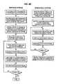
- FIG. 6A is a flow chart diagram depicting an operation procedure to acquire data using a downhole communications system in accordance with preferred embodiments of the present invention.
- FIG. 6B is a flow chart diagram depicting an operation procedure to control downhole actuators using a downhole communications system in accordance with preferred embodiments of the present invention.
- Downhole communications system 100 preferably includes a surface unit 102 and a downhole communications package 104 .
- Surface unit 102 preferably includes a pressure wave generator 106 , a signal processing unit 108 , and pressure transducers 110 , 112 .
- Pressure wave generator 106 is shown as a piston-type pressure generator that includes a motor driven piston producing a reciprocal movement within a cylinder but may be of any type known in the art.
- Surface unit transmits, receives, and analyzes pressure wave signals to and from communications package 104 .
- Communications package 104 is shown located downhole in an annulus 114 between strings of production tubing 116 and casing 118 .
- packers 120 , 122 isolate sections of strings 116 , 118 so that distinct measurements in a zone of investigation 124 can be taken by downhole sensor package 126 (downhole sensor).
- Downhole sensor package 126 can be of any type known to one skilled in the field of hydrocarbon production, but typically will include pressure and temperature sensing devices that are capable of operating with minimal power input.
- Downhole sensor package 126 is preferably connected to a downhole control module 128 where the data therefrom can be accumulated, converted to digital bit streams, and transmitted to surface unit 102 for analysis.
- additional sensors 130 from production tubing bore 132 or other zones of investigation may also tie back to downhole control module 128 for transmission to surface unit 102 .
- control module 128 is constructed as a low power-consuming computational device capable of regulating numerous downhole processes. While control module 128 may be constructed as several individual components including, but not limited to, data processing, valve actuation, data transmission, and electrical regulatory components connected together by a communication protocols, module 128 is shown in Figure schematically as a single component for simplicity.
- a power generation and storage system 134 is preferably connected to control module 128 .
- Power generation and storage system 134 preferably includes an energy storage module (not shown in detail) and an energy conversion module (not shown in detail).
- Energy storage module is preferably a bank of capacitors or any other energy storage means known to one skilled in the art.
- Energy conversion module preferably converts mechanical energy to electrical energy through magnetostrictive, electrostrictive, or piezoelectric materials.
- the converter can be based on any appropriate mechanical to electrical energy conversion device, for example, a hydrophone based on electromagnetic induction.
- Piezoelectric materials generate electrical currents when placed under pressures.
- pressure waves generate electric charges between two electrodes separated by piezoelectric material with appropriate strain-sensitive orientation.
- the more piezoelectric material used the more electric charge generated. Therefore, in order to be feasible as a downhole generator, a stack of multi-layer piezoelectric material interlaced with metal electrodes is often employed. These stacked materials are typically constructed as a cylindrical or tubular shape.
- d 33 is the piezoelectric coefficient of the material used.
- the electrical current generated would have amplitude of 4.4 mA. This current would then be routed to charge a large capacitor C s through a full-wave rectifier as shown in FIG. 2 .
- the piezoelectric device is represented by a current source in parallel with its intrinsic capacitance C p and shunt resistance R p .
- the full-wave rectifier is implemented by 4 diodes D 1 , D 2 , D 3 , and D 4 .
- the charge storing capacitance C s is large compared with the intrinsic capacitance C p , most of the current generated by the piezoelectric device is charged into C s .
- the average direct current charging can be obtained by integrating the rectified current waveform over its period:
- I c 2 ⁇ ⁇ i Eq . ⁇ 2
- I c 2 ⁇ ⁇ i Eq . ⁇ 2
- the voltage monitor and isolation switch in FIG. 2 can be used to help save energy whereby the charging capacitor is isolated from the load circuits until the voltage of the capacitor exceeds a predetermined level. When the voltage on the capacitor exceeds this level, the accumulation of sufficient energy for an acquisition cycle is indicated and the DC-to-DC converter is used to convert the voltage across the capacitor to a level required by the load circuits in sensors and actuators.
- FIG. 3 shows a resonator system 150 created by adding a mass 152 to the energy conversion device (e.g. piezoelectric stack) 154 .
- Resonator system 150 is shown located in an annulus 156 formed between a string of casing 158 and a string of inner tubing 160 .
- the stiffness s and mass M of the converter 154 determine the un-damped resonance frequency ⁇ wherein:
- FIG. 3 illustrates another method using impedance matching to further improve energy conversion efficiency.
- the energy conversion device can be made relatively thin and long to reduce the stiffness thereof.
- the dynamic pressure is amplified by the ratio of the two areas A and A 2 .
- the static pressure is balanced through gaps 162 around the edge of the piston and through any balancing holes 164 drilled on it.
- single crystal piezoelectric materials e.g. quartz
- quartz single crystal piezoelectric materials
- the piezoelectric material can be immersed in a protective fluid such as silicone oil and contained within a pressure transparent barrier.
- a protective fluid such as silicone oil
- This barrier constructed as an elastomeric bladder or a metal bellows device, would allow downhole pressure to act upon the piezoelectric material without risk of allowing the working fluid (mud, water, etc.) to come into contact with, and damage the piezoelectric material.
- a magnetostrictive material such as TERFENOL-D may be used in place of piezoelectric material for mechanical to electrical converter.
- pressure waves acting thereupon produce a varying magnetization in the material, thereby inducing a current in a coiled wire that surrounds it.
- Magnetostrictive materials have the advantage of not degrading in performance over long term like piezoelectric materials.
- magnetostrictive devices generally will not have as high of conversion efficiency as the piezoelectric materials. For this reason, the selection of piezoelectric v. magnetostrictive materials will depend largely on the amount of energy needed to operate downhole sensors and transmit data therefrom back to the surface.
- downhole communications package 104 includes a telemetry modulator 136 to transmit data received and processed from sensors 126 and 130 to surface unit 102 .
- Telemetry modulator 136 preferably includes a low power actuator or solenoid and a pressure wave modulator (e.g. a Helmholtz-type resonator). Together, the modulator and actuator function to modify the pressure waves sent from pressure wave generator 106 of surface unit 102 . Typically, these waves are transmitted from the surface unit to the downhole communications package where they are reflected and returned to the surface.
- the reflected waves are “shifted” in phase or otherwise modified (e.g.
- Communications begins when a continuous sinusoidal carrier wave is generated by pressure wave generator 106 at the surface. This wave propagates down annulus 114 between tubing 116 and casing 118 and is reflected at a downhole termination (typically a packer 120 , 122 ) and returns to the surface.
- a downhole termination typically a packer 120 , 122
- the frequency of the carrier wave is tuned to a resonance frequency of a downhole Helmholtz resonator assembly (telemetry module 136 ) that includes a fluid filled volume 138 and a narrow access tube 140 that links the fluid in reservoir 138 to the fluid in annulus 114 .
- Valve 142 is preferably constructed as an actuator that includes an armature 144 , and valve plunger 146 corresponding to a plunger seat 148 at the end of tube 140 .
- valve 142 is closed and annulus 114 is terminated rigidly by packer 120 . Therefore, the incoming wave is to be reflected back to the surface without any change in phase.
- valve 142 is opened and the low impedance of resonator 136 ( 138 + 140 ) becomes the termination to the annulus.
- the resultant reflected wave is phase-shifted by approximately 180° when received at surface unit 102 . Therefore, the binary data is sent by the reflected pressure wave with a binary phase-shifting keying (BPSK) modulation.
- Pressure transducers 110 , 112 at surface detect the reflected pressure wave and submit their output to signal processing unit 108 where the reflected wave is separated from the interference of the down-going carrier wave and demodulated to decrypt the transmitted data.
- BPSK binary phase-shifting keying
- the resonator inlet tube 140 and the valve 142 may be housed within a pressure transparent bellows or bladder.
- Such devices would be hydraulically transparent and preferably filled with a clean fluid such as silicone oil or de-ionized water to maximize the life of telemetry modulator 136 .
- This design is capable of providing fluid isolation while still permitting pressure communication therethrough.
- CMOS devices For permanent monitoring applications as envisioned by preferred embodiments of the present invention, it is important to minimize power consumption for the sensor electronics as well as the data telemetry modulation system.
- Low power components such as CMOS devices, should be used in electronic circuits and optimized power management should be implemented wherever possible by switching off supply to sensors and circuits when not in use.
- One area where power conservation is possible is in relation to the transmittal of data to surface unit 102 through telemetry module 136 .
- a bi-stable actuator 142 assembly is preferred by embodiments of the present invention. Normally, for typical electrical actuators, power is needed to drive or actuate armature 144 and plunger 146 only in a single direction, after which they return to their steady-state position. Therefore, using the example above, power would only be required to be sent to actuator 142 from power module 134 when a digit “1” is to be sent. Furthermore, power from module 134 (through control module 128 ) would be required to be maintained the entire time while a digit “1” was being sent.
- a bi-stable actuator 142 would only require action and power from control module 128 whenever a change in position of armature 144 and plunger 146 is required. Therefore, power from control module 128 would only be necessary to briefly reposition plunger 146 and would not be required to be maintained throughout the sending of the digit “1” as required with a traditional actuator.
- Such bi-stable actuators have built-in potential energy (through permanent magnets) to maintain the switching device in one of the two stable positions. Only a low level of electrical power, in the form of a very short duration trigger pulse, is needed to tip the energy balance so that actuator 144 can switch to the other position.
- FIG. 5A depicts energy input for a conventional actuator assembly
- FIG. 5B depicts the same for a bi-stable actuator assembly.
- power input is only required during the transition period of a digit change, e.g. from “1” to “0” or vice versa.
- Power is saved when the width of the triggering pulse is smaller than 50% of the digit time as can be seen by comparing FIGS. 5A-5B .
- the bi-stable actuator no power will be consumed if the digit sent does not change.
- the total power consumption for telemetry depends on the total number of digit transitions, not the duration of transmission for a particular digit (or the transmission frequency). For instance, if four measurements of 15-bit each are to be sent with 50% “0” and 50% “1” in the data and about 30 switching operations are needed, then a 30 W solenoid with a trigger pulse width of 20 ms would consume 0.6 J per switch operation, making the total power consumption 18 J.
- the process typically begins with the pumping of water, via a surface pipe, into the annulus between a string of casing and a string of tubing until the pressure reaches a certain level, typically to a few hundred pounds per square inch.
- a surface pressure wave generator generates pressure waves to energize the down hole mechanical to electrical energy converter over a pre-determined period of time, T.
- pressure wave generator sends a pressure wave of appropriate frequency, typically from 1 Hz to 100 Hz, and appropriate amplitude, typically a few tens to a few hundreds of pounds per square inch, through surface pipe to downhole assembly.
- the down-hole energy converter converts the pressure wave energy into electrical energy with the electrical current generated thereby stored in a capacitor bank or storage module.
- the capacitance of storage module is sufficient to provide a smooth supply voltage to the array of downhole devices during the data acquisition and telemetry period.
- the energizing process takes a few tens of minutes to build up a sufficient amount of electrical energy in the capacitor bank.
- an electronic energy monitor can monitor the energy level in the storage module and can close an isolation switch (as shown in FIG. 3 ) when an appropriate level is reached to power up the electronics and sensors.
- sensor electronics require a warming up period before they are capable of making accurate measurements.
- a downhole controller can accommodate this phenomenon by switching on the sensors before actual measurements are to be taken.
- the warm-up period will vary by design and manufacture of the sensor components, but will typically be several minutes in length.
- the pressure wave source on the surface can be kept running to supply energy to the sensors and the storage module.
- the data acquisition phase begins.
- downhole sensors measure various parameters and transmit data relating to those measurements to the control module.
- the control module receives these measurements and converts them to digital codes and stores them for transmission to the surface.
- the resulting information is ready to be transmitted to the surface unit through binary bit stream telemetry.
- the downhole sensors are switched off to maximize power available to the telemetry operation.
- the frequency and/or amplitude of the pressure wave generator may need to be changed to differentiate a telemetry wave condition from an energy wave condition.
- This differentiation may be necessary or desirable for a variety of reasons.
- the design and construction of both the telemetry modulator and energy converter might be such that they each have distinct optimal operating conditions.
- the differentiation can also be used to signal to downhole sensors to switch from data accumulation (and energy conversion) to data telemetry mode.
- data telemetry module and energy conversion module can nonetheless be configured so that such a frequency and/or amplitude change is not necessary.
- the downhole communications system sends a signal indicating that acquired data is ready for transmission to the surface.
- the communications system can send a measurement of the amount of energy stored in the downhole capacitor to the surface unit so that it can determine whether the downhole system has sufficient energy to supply the entire telemetry operation. If the surface unit determines that insufficient energy is retained within the downhole energy storage device, a second energizing operation can be initiated to charge the storage device (capacitor) to obtain the necessary amount of energy.
- the processor in the downhole communications system can be configured to calculate the amount of energy needed in the capacitor to transmit the necessary data and can delay sending the ready signal to the surface until sufficiently charged.
- two surface pressure wave sources with different frequencies can be operated at the same time, one for continuous energizing during telemetry and the other for data transmission and modulation.
- Data acquisition is complete when all data stored within the downhole control module has been transmitted to the surface unit.
- the surface pressure wave generator can be deactivated, thereby allowing the sensors in the downhole communications system to consume the remaining power and shut down.
- the surface wave generator assembly can again be activated to begin the charging phase once again.
- the downhole system can send a system ready message to the surface unit.
- the surface unit can then send a pressure wave message containing instructions relating to the downhole operations to the control module.
- These instructions can include, but are not limited to, directions as to which sensors data is to be recorded or transmitted from and, in multi-actuator systems, which actuator transmission is desired to be received from.
- the instructions are preferably detected by a downhole pressure transducer connected to control module for deciphering and execution downhole.
- a message containing the valve address and the operation command can be sent.
- the downhole control module after receiving the instruction, can open a low power valve enabling the access to the hydraulic control line that connects the relevant valve.
- the downhole system then signals to surface that the down-hole control line is enabled and ready for actuation from the surface.
- the completion valve/actuator can then be operated from the surface by pumping up or bleeding down annulus pressure. This pressure increase or decrease is transmitted through the down-hole hydraulic control line to reach the valve/actuator.
- the downhole control module can detect the status of the valve and transmit to the surface whether or not the actuation was a success. As can be seen in the loop in FIG.
- the surface and down-hole systems can repeat the actuation cycle as necessary.
- the downhole communications system can disable the relevant control line, so that actuation of other devices can be performed.
- the surface unit can be constructed to be easily removed and relocated to a new well to perform similar tasks.
Abstract
Description
-
- i) Application Number 0320804.8, entitled “DOWNHOLE POWER GENERATION AND COMMUNICATIONS APPARATUS AND METHOD,” filed in the United Kingdom on Sep. 5, 2003; and
- ii) Application Number PCT/GB2004/003753, entitled “DOWNHOLE POWER GENERATION AND COMMUNICATIONS APPARATUS AND METHOD,” filed under the PCT on Sep. 2, 2004;
- All of which are commonly assigned to assignee of the present invention and hereby incorporated by reference in their entirety.
i=d33nAωP Eq. 1
where d33 is the piezoelectric coefficient of the material used. Assuming a wave, with 0.1 MPa (1-bar) amplitude and 20 Hz frequency applied to a 100 layer piezoelectric stack with a coefficient of 3.5×10⁻¹⁰ C/N (PZT Ceramic) and a cross-sectional area of 0.01 m2, the electrical current generated would have amplitude of 4.4 mA. This current would then be routed to charge a large capacitor Cs through a full-wave rectifier as shown in
During a finite charging period, Ic can be approximately equivalent to a constant charging current, and the electrical energy stored in Cs increases with charging time, T. Therefore:
Taking Ic to be 2.8 mA and Cs to be 0.01 F, the energy stored in Cs can reach 348 joules after 10 minutes of charging. If the electronics of the down-hole sensors have a power consumption of 1 Watt, then, without considering various losses, this energy could sustain data acquisition for 348 seconds. Charging time can be increased if a longer acquisition or higher power consumption is required.
The fluid damping effect will make the actual resonance frequency lower than the un-damped frequency ω. The pressure wave frequency generated on surface can be matched to this actual resonance frequency to generate the maximum electrical energy output.
F=pA Eq. 5
that converts to a pressure on the active material:
Therefore, the dynamic pressure is amplified by the ratio of the two areas A and A2. The static pressure is balanced through
Claims (18)
Applications Claiming Priority (3)
| Application Number | Priority Date | Filing Date | Title |
|---|---|---|---|
| GB0320804.8 | 2003-09-05 | ||
| GB0320804A GB2405725B (en) | 2003-09-05 | 2003-09-05 | Borehole telemetry system |
| PCT/GB2004/003753 WO2005024177A1 (en) | 2003-09-05 | 2004-09-02 | Downhole power generation and communications apparatus and method |
Publications (2)
| Publication Number | Publication Date |
|---|---|
| US20070194947A1 US20070194947A1 (en) | 2007-08-23 |
| US8009059B2 true US8009059B2 (en) | 2011-08-30 |
Family
ID=29226539
Family Applications (2)
| Application Number | Title | Priority Date | Filing Date |
|---|---|---|---|
| US10/569,514 Expired - Fee Related US7990282B2 (en) | 2003-09-05 | 2004-08-23 | Borehole telemetry system |
| US10/569,707 Expired - Fee Related US8009059B2 (en) | 2003-09-05 | 2004-09-02 | Downhole power generation and communications apparatus and method |
Family Applications Before (1)
| Application Number | Title | Priority Date | Filing Date |
|---|---|---|---|
| US10/569,514 Expired - Fee Related US7990282B2 (en) | 2003-09-05 | 2004-08-23 | Borehole telemetry system |
Country Status (4)
| Country | Link |
|---|---|
| US (2) | US7990282B2 (en) |
| CA (2) | CA2537189C (en) |
| GB (2) | GB2405725B (en) |
| WO (2) | WO2005024182A1 (en) |
Cited By (13)
| Publication number | Priority date | Publication date | Assignee | Title |
|---|---|---|---|---|
| US20100000820A1 (en) * | 2006-09-19 | 2010-01-07 | Schlumberger Technology Corporation | Pressure-balanced electromechanical converter |
| US20100149919A1 (en) * | 2008-12-12 | 2010-06-17 | Schlumberger Technology Corporation | Downhole telemetry system |
| US20110114324A1 (en) * | 2009-11-13 | 2011-05-19 | Baker Hughes Incorporated | Modular hydraulic operator for a subterranean tool |
| US20110290504A1 (en) * | 2008-10-02 | 2011-12-01 | Petrowell Limited | Control system |
| WO2012103553A1 (en) * | 2011-01-28 | 2012-08-02 | Oscilla Power Inc. | Energy harvesting methods and devices, and applications thereof |
| CN102721751A (en) * | 2012-05-28 | 2012-10-10 | 华中科技大学 | Magnetostrictive guided wave receiving sensor |
| US20140123748A1 (en) * | 2012-11-04 | 2014-05-08 | Schlumberger Technology Corporation | Borehole Microseismic Systems and Methods |
| WO2016014221A1 (en) | 2014-06-30 | 2016-01-28 | Saudi Arabian Oil Company | Wireless power transmission to downhole well equipment |
| US9388812B2 (en) | 2014-01-29 | 2016-07-12 | Schlumberger Technology Corporation | Wireless sensor system for electric submersible pump |
| US9938821B2 (en) | 2013-08-29 | 2018-04-10 | Halliburton Energy Services, Inc. | Systems and methods for casing detection using resonant structures |
| US20180347319A1 (en) * | 2017-05-31 | 2018-12-06 | Bona Developments Inc. | Self-powered wellbore motor |
| US10753180B2 (en) | 2016-09-19 | 2020-08-25 | Halliburton Energy Services, Inc. | Powering downhole components in subsurface formations behind casing |
| WO2021096836A1 (en) * | 2019-11-12 | 2021-05-20 | Baker Hughes Oilfield Operations Llc | Systems and methods for harvesting vibration energy using a hybrid device |
Families Citing this family (45)
| Publication number | Priority date | Publication date | Assignee | Title |
|---|---|---|---|---|
| GB2405725B (en) | 2003-09-05 | 2006-11-01 | Schlumberger Holdings | Borehole telemetry system |
| US7348893B2 (en) | 2004-12-22 | 2008-03-25 | Schlumberger Technology Corporation | Borehole communication and measurement system |
| US7352111B2 (en) | 2005-12-01 | 2008-04-01 | Schlumberger Technology Corporation | Electroactive polymer pumping system |
| GB2433112B (en) | 2005-12-06 | 2008-07-09 | Schlumberger Holdings | Borehole telemetry system |
| CN101529276B (en) * | 2006-09-08 | 2013-03-20 | 雪佛龙美国公司 | A telemetry apparatus and method for monitoring a borehole |
| GB2447691B (en) | 2007-03-23 | 2009-10-28 | Schlumberger Holdings | Flow measuring apparatus and method |
| US8872670B2 (en) * | 2007-03-23 | 2014-10-28 | Schlumberger Technology Corporation | Compliance telemetry |
| GB2461194B (en) * | 2007-07-30 | 2010-06-23 | Schlumberger Holdings | Methods and systems for use with wellbores |
| US20100133833A1 (en) * | 2008-10-24 | 2010-06-03 | Bp Corporation North America Inc. | Electrical power generation for downhole exploration or production devices |
| US8330617B2 (en) * | 2009-01-16 | 2012-12-11 | Schlumberger Technology Corporation | Wireless power and telemetry transmission between connections of well completions |
| US20130128697A1 (en) * | 2009-12-28 | 2013-05-23 | Erwann Lemenager | Downhole Communication System |
| US8322447B2 (en) * | 2009-12-31 | 2012-12-04 | Schlumberger Technology Corporation | Generating power in a well |
| KR101229361B1 (en) * | 2010-03-10 | 2013-02-05 | 엘지전자 주식회사 | Communicating apparatus, air conditioning system including the same and communicating method using refrigerant pipes thereof |
| MX2010013155A (en) * | 2010-11-30 | 2012-05-31 | Schlumberger Technology Bv | Arrangement for sensing the bottom of a well. |
| US20130214619A1 (en) * | 2011-08-23 | 2013-08-22 | Oscilla Power Inc. | Method and device for mechanical energy harvesting |
| US8759993B2 (en) | 2012-05-18 | 2014-06-24 | Cameron International Corporation | Energy harvesting system |
| WO2013185064A1 (en) * | 2012-06-07 | 2013-12-12 | California Institute Of Technology | Communication in pipes using acoustic modems that provide minimal obstruction to fluid flow |
| GB2504209B (en) * | 2012-06-18 | 2014-10-15 | Mi Llc | Methods and systems of increasing signal strength of oilfield tools |
| WO2014121403A1 (en) * | 2013-02-07 | 2014-08-14 | Xact Downhole Telemetry Inc. | Acoustic transmitter for transmitting a signal through a downhole medium |
| CA2902672C (en) * | 2013-02-27 | 2016-08-16 | Evolution Engineering Inc. | System and method for managing batteries for use in a downhole drilling application |
| US9461469B2 (en) * | 2013-05-31 | 2016-10-04 | Schlumberger Technology Corporation | Electrical power grid for a downhole BHA |
| US9739120B2 (en) * | 2013-07-23 | 2017-08-22 | Halliburton Energy Services, Inc. | Electrical power storage for downhole tools |
| US9500074B2 (en) | 2013-07-31 | 2016-11-22 | Halliburton Energy Services, Inc. | Acoustic coupling of electrical power and data between downhole devices |
| WO2015016927A1 (en) * | 2013-07-31 | 2015-02-05 | Halliburton Energy Services, Inc. | Acoustic coupling of electrical power and data between downhole devices |
| US9523272B2 (en) | 2013-12-28 | 2016-12-20 | Halliburton Energy Services, Inc. | Amplification of data-encoded sound waves within a resonant area |
| US20150198034A1 (en) * | 2014-01-16 | 2015-07-16 | Baker Hughes Incorporated | Production fluid monitoring system including a downhole acousting sensing system having a downhole pulsator |
| GB2522258A (en) * | 2014-01-20 | 2015-07-22 | Tendeka As | Wellbore energy collection |
| US10125558B2 (en) * | 2014-05-13 | 2018-11-13 | Schlumberger Technology Corporation | Pumps-off annular pressure while drilling system |
| US9593557B2 (en) * | 2014-09-25 | 2017-03-14 | Chevron U.S.A. Inc | System and method for autonomous downhole power generation |
| WO2016089398A1 (en) * | 2014-12-03 | 2016-06-09 | Schlumberger Canada Limited | System and method for isolating capacitor bank |
| WO2016148671A1 (en) * | 2015-03-13 | 2016-09-22 | Halliburton Energy Services, Inc. | Methods and systems for maintaining optical transparency during particle image acquisition |
| US9869174B2 (en) * | 2015-04-28 | 2018-01-16 | Vetco Gray Inc. | System and method for monitoring tool orientation in a well |
| US10419018B2 (en) | 2015-05-08 | 2019-09-17 | Schlumberger Technology Corporation | Real-time annulus pressure while drilling for formation integrity test |
| WO2017024083A1 (en) * | 2015-08-03 | 2017-02-09 | Halliburton Energy Services, Inc. | Electromagnetic telemetry using capacitive electrodes |
| US10246994B2 (en) * | 2015-09-10 | 2019-04-02 | Cameron International Corporation | System for communicating data via fluid lines |
| US20180230799A1 (en) * | 2015-10-08 | 2018-08-16 | Halliburton Energy Services, Inc. | Communication to a downhole tool by acoustic waveguide transfer |
| US10590758B2 (en) | 2015-11-12 | 2020-03-17 | Schlumberger Technology Corporation | Noise reduction for tubewave measurements |
| WO2017105418A1 (en) * | 2015-12-16 | 2017-06-22 | Halliburton Energy Services, Inc. | Data transmission across downhole connections |
| CN106014393B (en) * | 2016-05-19 | 2023-04-07 | 中国石油天然气集团有限公司 | Device for acoustic wave propagation magnetic positioning measurement data and using method thereof |
| WO2018004369A1 (en) | 2016-07-01 | 2018-01-04 | Шлюмберже Канада Лимитед | Method and system for locating downhole objects which reflect a hydraulic signal |
| US20180175646A1 (en) * | 2016-12-15 | 2018-06-21 | Chen-Source Inc. | Charging cabinet |
| DK3601735T3 (en) * | 2017-03-31 | 2023-03-27 | Metrol Tech Ltd | Monitoring well installations |
| CN108730104B (en) | 2017-04-24 | 2020-11-24 | 通用电气公司 | Underground power generation system and optimized power control method thereof |
| US10830919B1 (en) * | 2017-10-26 | 2020-11-10 | Stewart Thomas Taylor | Real-time mapping of induced fracture geometry by RFID networks |
| BR112020008295B1 (en) * | 2017-12-29 | 2022-12-06 | Halliburton Energy Services, Inc | SYSTEM AND METHOD |
Citations (23)
| Publication number | Priority date | Publication date | Assignee | Title |
|---|---|---|---|---|
| US3659259A (en) | 1968-01-23 | 1972-04-25 | Halliburton Co | Method and apparatus for telemetering information through well bores |
| US3789355A (en) | 1971-12-28 | 1974-01-29 | Mobil Oil Corp | Method of and apparatus for logging while drilling |
| US3964556A (en) | 1974-07-10 | 1976-06-22 | Gearhart-Owen Industries, Inc. | Downhole signaling system |
| US4669068A (en) * | 1983-04-18 | 1987-05-26 | Frederick Klatt | Power transmission apparatus for enclosed fluid systems |
| US5283768A (en) | 1991-06-14 | 1994-02-01 | Baker Hughes Incorporated | Borehole liquid acoustic wave transducer |
| EP0685628A1 (en) | 1994-06-02 | 1995-12-06 | Sofitech N.V. | Whipstock orientation method and system |
| WO1996009561A1 (en) | 1994-09-21 | 1996-03-28 | Sensor Dynamics Limited | Apparatus for sensor location |
| US5839508A (en) | 1995-02-09 | 1998-11-24 | Baker Hughes Incorporated | Downhole apparatus for generating electrical power in a well |
| US5924499A (en) | 1997-04-21 | 1999-07-20 | Halliburton Energy Services, Inc. | Acoustic data link and formation property sensor for downhole MWD system |
| GB2343537A (en) | 1998-08-13 | 2000-05-10 | Baker Hughes Inc | An acoustic transmission system |
| GB2348029A (en) | 1995-10-20 | 2000-09-20 | Baker Hughes Inc | Performing an operation in a wellbore |
| US6172614B1 (en) | 1998-07-13 | 2001-01-09 | Halliburton Energy Services, Inc. | Method and apparatus for remote actuation of a downhole device using a resonant chamber |
| US6304176B1 (en) * | 1998-09-30 | 2001-10-16 | Rockwell Technologies, Llc | Parasitically powered sensing device |
| WO2002027139A1 (en) | 2000-09-28 | 2002-04-04 | Tubel Paulo S | Method and system for wireless communications for downhole applications |
| US6464011B2 (en) * | 1995-02-09 | 2002-10-15 | Baker Hughes Incorporated | Production well telemetry system and method |
| US20030026167A1 (en) | 2001-07-25 | 2003-02-06 | Baker Hughes Incorporated | System and methods for detecting pressure signals generated by a downhole actuator |
| GB2380065A (en) | 1998-10-08 | 2003-03-26 | Camcon Ltd | Magnetic actuator |
| EP1302624A1 (en) | 2001-10-12 | 2003-04-16 | Halliburton Energy Services, Inc. | Locating joints in coiled tubing operations |
| US20030086336A1 (en) | 2001-11-07 | 2003-05-08 | Baker Hughes, Inc. | Semi-passive two way borehole communication apparatus and method |
| US20030116969A1 (en) | 2001-12-20 | 2003-06-26 | Skinner Neal G. | Annulus pressure operated electric power generator |
| WO2003067029A1 (en) | 2002-02-08 | 2003-08-14 | Poseidon Group As | Autonomous downhole/reservoir monitoring and data transfer system |
| GB2399921A (en) | 2003-03-26 | 2004-09-29 | Schlumberger Holdings | Borehole telemetry system |
| US7397388B2 (en) * | 2003-03-26 | 2008-07-08 | Schlumberger Technology Corporation | Borehold telemetry system |
Family Cites Families (1)
| Publication number | Priority date | Publication date | Assignee | Title |
|---|---|---|---|---|
| GB2405725B (en) | 2003-09-05 | 2006-11-01 | Schlumberger Holdings | Borehole telemetry system |
-
2003
- 2003-09-05 GB GB0320804A patent/GB2405725B/en not_active Expired - Fee Related
-
2004
- 2004-08-23 CA CA2537189A patent/CA2537189C/en not_active Expired - Fee Related
- 2004-08-23 WO PCT/GB2004/003597 patent/WO2005024182A1/en active Application Filing
- 2004-08-23 US US10/569,514 patent/US7990282B2/en not_active Expired - Fee Related
- 2004-09-02 GB GB0604384A patent/GB2422395B/en not_active Expired - Fee Related
- 2004-09-02 US US10/569,707 patent/US8009059B2/en not_active Expired - Fee Related
- 2004-09-02 CA CA2537186A patent/CA2537186C/en not_active Expired - Fee Related
- 2004-09-02 WO PCT/GB2004/003753 patent/WO2005024177A1/en active Application Filing
Patent Citations (25)
| Publication number | Priority date | Publication date | Assignee | Title |
|---|---|---|---|---|
| US3659259A (en) | 1968-01-23 | 1972-04-25 | Halliburton Co | Method and apparatus for telemetering information through well bores |
| US3789355A (en) | 1971-12-28 | 1974-01-29 | Mobil Oil Corp | Method of and apparatus for logging while drilling |
| US3964556A (en) | 1974-07-10 | 1976-06-22 | Gearhart-Owen Industries, Inc. | Downhole signaling system |
| US4669068A (en) * | 1983-04-18 | 1987-05-26 | Frederick Klatt | Power transmission apparatus for enclosed fluid systems |
| US5283768A (en) | 1991-06-14 | 1994-02-01 | Baker Hughes Incorporated | Borehole liquid acoustic wave transducer |
| EP0685628A1 (en) | 1994-06-02 | 1995-12-06 | Sofitech N.V. | Whipstock orientation method and system |
| WO1996009561A1 (en) | 1994-09-21 | 1996-03-28 | Sensor Dynamics Limited | Apparatus for sensor location |
| US5839508A (en) | 1995-02-09 | 1998-11-24 | Baker Hughes Incorporated | Downhole apparatus for generating electrical power in a well |
| US6442105B1 (en) | 1995-02-09 | 2002-08-27 | Baker Hughes Incorporated | Acoustic transmission system |
| US6464011B2 (en) * | 1995-02-09 | 2002-10-15 | Baker Hughes Incorporated | Production well telemetry system and method |
| GB2348029A (en) | 1995-10-20 | 2000-09-20 | Baker Hughes Inc | Performing an operation in a wellbore |
| US5924499A (en) | 1997-04-21 | 1999-07-20 | Halliburton Energy Services, Inc. | Acoustic data link and formation property sensor for downhole MWD system |
| US6172614B1 (en) | 1998-07-13 | 2001-01-09 | Halliburton Energy Services, Inc. | Method and apparatus for remote actuation of a downhole device using a resonant chamber |
| GB2343537A (en) | 1998-08-13 | 2000-05-10 | Baker Hughes Inc | An acoustic transmission system |
| US6304176B1 (en) * | 1998-09-30 | 2001-10-16 | Rockwell Technologies, Llc | Parasitically powered sensing device |
| GB2380065A (en) | 1998-10-08 | 2003-03-26 | Camcon Ltd | Magnetic actuator |
| WO2002027139A1 (en) | 2000-09-28 | 2002-04-04 | Tubel Paulo S | Method and system for wireless communications for downhole applications |
| US20030026167A1 (en) | 2001-07-25 | 2003-02-06 | Baker Hughes Incorporated | System and methods for detecting pressure signals generated by a downhole actuator |
| EP1302624A1 (en) | 2001-10-12 | 2003-04-16 | Halliburton Energy Services, Inc. | Locating joints in coiled tubing operations |
| US20030086336A1 (en) | 2001-11-07 | 2003-05-08 | Baker Hughes, Inc. | Semi-passive two way borehole communication apparatus and method |
| US6757218B2 (en) * | 2001-11-07 | 2004-06-29 | Baker Hughes Incorporated | Semi-passive two way borehole communication apparatus and method |
| US20030116969A1 (en) | 2001-12-20 | 2003-06-26 | Skinner Neal G. | Annulus pressure operated electric power generator |
| WO2003067029A1 (en) | 2002-02-08 | 2003-08-14 | Poseidon Group As | Autonomous downhole/reservoir monitoring and data transfer system |
| GB2399921A (en) | 2003-03-26 | 2004-09-29 | Schlumberger Holdings | Borehole telemetry system |
| US7397388B2 (en) * | 2003-03-26 | 2008-07-08 | Schlumberger Technology Corporation | Borehold telemetry system |
Cited By (22)
| Publication number | Priority date | Publication date | Assignee | Title |
|---|---|---|---|---|
| US8384270B2 (en) | 2006-09-19 | 2013-02-26 | Schlumberger Technology Corporation | Pressure-balanced electromechanical converter |
| US20100000820A1 (en) * | 2006-09-19 | 2010-01-07 | Schlumberger Technology Corporation | Pressure-balanced electromechanical converter |
| US20110290504A1 (en) * | 2008-10-02 | 2011-12-01 | Petrowell Limited | Control system |
| US8950503B2 (en) * | 2008-10-02 | 2015-02-10 | Petrowell Limited | Control system |
| US20100149919A1 (en) * | 2008-12-12 | 2010-06-17 | Schlumberger Technology Corporation | Downhole telemetry system |
| US9042200B2 (en) * | 2008-12-12 | 2015-05-26 | Schlumberger Technology Corporation | Downhole telemetry system |
| US8261817B2 (en) | 2009-11-13 | 2012-09-11 | Baker Hughes Incorporated | Modular hydraulic operator for a subterranean tool |
| US20110114324A1 (en) * | 2009-11-13 | 2011-05-19 | Baker Hughes Incorporated | Modular hydraulic operator for a subterranean tool |
| WO2012103553A1 (en) * | 2011-01-28 | 2012-08-02 | Oscilla Power Inc. | Energy harvesting methods and devices, and applications thereof |
| CN102721751A (en) * | 2012-05-28 | 2012-10-10 | 华中科技大学 | Magnetostrictive guided wave receiving sensor |
| US9416641B2 (en) * | 2012-11-04 | 2016-08-16 | Schlumberger Technology Corporation | Borehole microseismic systems and methods |
| US20140123748A1 (en) * | 2012-11-04 | 2014-05-08 | Schlumberger Technology Corporation | Borehole Microseismic Systems and Methods |
| US9938821B2 (en) | 2013-08-29 | 2018-04-10 | Halliburton Energy Services, Inc. | Systems and methods for casing detection using resonant structures |
| US9388812B2 (en) | 2014-01-29 | 2016-07-12 | Schlumberger Technology Corporation | Wireless sensor system for electric submersible pump |
| WO2016014221A1 (en) | 2014-06-30 | 2016-01-28 | Saudi Arabian Oil Company | Wireless power transmission to downhole well equipment |
| US9810059B2 (en) | 2014-06-30 | 2017-11-07 | Saudi Arabian Oil Company | Wireless power transmission to downhole well equipment |
| US10753180B2 (en) | 2016-09-19 | 2020-08-25 | Halliburton Energy Services, Inc. | Powering downhole components in subsurface formations behind casing |
| US20180347319A1 (en) * | 2017-05-31 | 2018-12-06 | Bona Developments Inc. | Self-powered wellbore motor |
| US11713653B2 (en) * | 2017-05-31 | 2023-08-01 | Bona Developments Inc. | Self-powered wellbore motor |
| WO2021096836A1 (en) * | 2019-11-12 | 2021-05-20 | Baker Hughes Oilfield Operations Llc | Systems and methods for harvesting vibration energy using a hybrid device |
| GB2605521A (en) * | 2019-11-12 | 2022-10-05 | Baker Hughes Oilfield Operations Llc | Systems and methods for harvesting vibration energy using a hybrid device |
| US11677269B2 (en) | 2019-11-12 | 2023-06-13 | Baker Hughes Oilfield Operations Llc | Systems and methods for harvesting vibration energy using a hybrid device |
Also Published As
| Publication number | Publication date |
|---|---|
| GB2422395B (en) | 2007-12-19 |
| US20070227776A1 (en) | 2007-10-04 |
| GB2405725A (en) | 2005-03-09 |
| CA2537186A1 (en) | 2005-03-17 |
| US7990282B2 (en) | 2011-08-02 |
| WO2005024182A1 (en) | 2005-03-17 |
| GB0604384D0 (en) | 2006-04-12 |
| CA2537186C (en) | 2012-05-29 |
| GB0320804D0 (en) | 2003-10-08 |
| GB2405725B (en) | 2006-11-01 |
| CA2537189C (en) | 2012-04-24 |
| CA2537189A1 (en) | 2005-03-17 |
| US20070194947A1 (en) | 2007-08-23 |
| GB2422395A (en) | 2006-07-26 |
| WO2005024177A1 (en) | 2005-03-17 |
Similar Documents
| Publication | Publication Date | Title |
|---|---|---|
| US8009059B2 (en) | Downhole power generation and communications apparatus and method | |
| US7397388B2 (en) | Borehold telemetry system | |
| US7994932B2 (en) | Borehole telemetry system | |
| US7834777B2 (en) | Downhole power source | |
| AU2005262362B2 (en) | Acoustic telemetry transceiver | |
| EP1750930B1 (en) | Downhole ultrasonic well cleaning device | |
| CA2570344C (en) | Apparatus and methods for self-powered communication and sensor network | |
| US20050207279A1 (en) | Apparatus and methods for self-powered communication and sensor network | |
| US6757218B2 (en) | Semi-passive two way borehole communication apparatus and method | |
| WO2004113677A1 (en) | Apparatus and method for self-powered communication and sensor network | |
| NO328231B1 (en) | System and method for detecting pressure signals generated by a down-hole actuator | |
| EP3097258B1 (en) | Wellbore energy collection | |
| CA2527751C (en) | Borehole telemetry system | |
| GB2437433A (en) | Free flowing tags powered by vibrational energy | |
| AU2021381497A1 (en) | Single crystal ultrasonic transducer with charge mode receiver | |
| GB2461194A (en) | Generating downhole power by converting acoustic waves into electrical energy | |
| GB2413348A (en) | Borehole communication using reflected acoustic signal |
Legal Events
| Date | Code | Title | Description |
|---|---|---|---|
| AS | Assignment |
Owner name: SCHLUMBERGER TECHNOLOGY CORPORATION, CONNECTICUT Free format text: ASSIGNMENT OF ASSIGNORS INTEREST;ASSIGNORS:HUANG, SONGMING;MONMONT, FRANCK;SADIKOGLU, KASIM;SIGNING DATES FROM 20060303 TO 20060918;REEL/FRAME:018310/0294 Owner name: SCHLUMBERGER TECHNOLOGY CORPORATION, CONNECTICUT Free format text: ASSIGNMENT OF ASSIGNORS INTEREST;ASSIGNORS:HUANG, SONGMING;MONMONT, FRANCK;SADIKOGLU, KASIM;REEL/FRAME:018310/0294;SIGNING DATES FROM 20060303 TO 20060918 |
|
| REMI | Maintenance fee reminder mailed | ||
| LAPS | Lapse for failure to pay maintenance fees | ||
| STCH | Information on status: patent discontinuation |
Free format text: PATENT EXPIRED DUE TO NONPAYMENT OF MAINTENANCE FEES UNDER 37 CFR 1.362 |
|
| FP | Lapsed due to failure to pay maintenance fee |
Effective date: 20150830 |