US8005206B1 - VDSL splitter - Google Patents
VDSL splitter Download PDFInfo
- Publication number
- US8005206B1 US8005206B1 US11/691,441 US69144107A US8005206B1 US 8005206 B1 US8005206 B1 US 8005206B1 US 69144107 A US69144107 A US 69144107A US 8005206 B1 US8005206 B1 US 8005206B1
- Authority
- US
- United States
- Prior art keywords
- vdsl
- signal
- capacitor
- pots
- stage
- Prior art date
- Legal status (The legal status is an assumption and is not a legal conclusion. Google has not performed a legal analysis and makes no representation as to the accuracy of the status listed.)
- Expired - Fee Related, expires
Links
Images


Classifications
-
- H—ELECTRICITY
- H04—ELECTRIC COMMUNICATION TECHNIQUE
- H04M—TELEPHONIC COMMUNICATION
- H04M11/00—Telephonic communication systems specially adapted for combination with other electrical systems
- H04M11/06—Simultaneous speech and data transmission, e.g. telegraphic transmission over the same conductors
- H04M11/062—Simultaneous speech and data transmission, e.g. telegraphic transmission over the same conductors using different frequency bands for speech and other data
Definitions
- the present invention relates to networks with transmission lines that carry both plain old telephone system (POTS) signals and very high speed data subscriber line (VDSL) signals over a common transmission line. More particularly, this present invention relates to a device for splitting the combined POTS and VDSL signal into individual signals for interference-free distribution at a telephone customer premise.
- POTS plain old telephone system
- VDSL very high speed data subscriber line
- the plain old telephone service is the service that delivers analog voice signals to a customer's home or office. These analog voice signals are generally transmitted at a frequency of less than 4 kHz via twisted pairs of copper wires. These same twisted pairs of wires often carry digital signals at significantly higher frequencies. For example, a twisted-pair wire may carry a very high digital subscriber line (VDSL) signal operating in the range of 25 kHz to 8.5 MHz, and above.
- VDSL digital subscriber line
- the low-frequency analog signals will be distributed through the location's telephone network across unshielded twisted-pair wires, with the high-frequency signal sent to a gateway device for distribution to local devices such as personal computers, set-top boxes, and so on.
- the VDSL signal may be distributed across a 100 ohm VDSL twisted pair network within the customer premise, or in other cases may need to be distributed across a 75 ohm coaxial cable network. Either way, separation of signals must be accomplished without introducing unwanted interference into the digital signal.
- Interference may be introduced into the VDSL signal from a number of sources.
- the low-frequency POTS signal may create transient interference signals during operation, for example, during on-hook, off-hook, and ringing.
- Other outside sources including sources at a customer location or premise, or from a central office, may introduce electromagnetic interference or other types of interference into the VDSL signal.
- splitter devices for interfacing customer premise equipment to the telephone network are already known in the industry. Many of these known splitter devices tend to incorporate extensive electronic schemes that include frequency splitters, multiple low-pass, high-pass, and bandpass filters, along with other active electronic devices. However, these known devices still often fail to satisfactorily eliminate transient signals introduced into the VDSL signals from the POTS circuit operation, especially in the higher frequency ranges. Furthermore, these devices tend to be sensitive to environmental changes, less robust, and sometimes more expensive than simpler analog devices.
- VDSL splitter located at a telephone customer premise and adapted to receive an incoming multi-frequency signal comprised of a low-frequency POTS signal and a high-frequency VDSL signal, and output separate, POTS and VDSL signals.
- the VDSL splitter includes an input port, connections for tapping the incoming signal, a POTS signal conditioning network, a VDSL signal conditioning network, and a pair of output ports.
- the POTS signal conditioning network includes a common mode choke and a multi-stage POTS low-pass filter.
- the POTS signal conditioning network substantially attenuates high-frequency signal components, allowing the DC to 4 KHz portion of the signal to pass.
- the VDSL signal conditioning network may include any combination of a voltage blocker, VDSL high-pass filter, and a multi-stage VDSL low-pass filter, attenuating portions of the incoming multi-frequency signal below and above the VDSL frequency range.
- the roll-off rate of the VDSL low-pass filter is steeper than the roll-off rate of the VDSL high-pass filter.
- a pair of output ports couples the POTS signal conditioning network and VDSL signal conditioning network outputs to premise wiring.
- VDSL may not include a voltage blocker, a VDSL high-pass filter, or a VDSL low-pass filter.
- the VDSL high-pass filter and VDSL low-pass filters are combined into a single bandpass filter.
- the VDSL signal conditioning network may not include a VDSL low-pass filter so as to allow all high-frequency portions of the VDSL signal to pass through the VDSL signal conditioning network, unfiltered.
- the output port is adapted to couple the VDSL output of the VDSL splitter to a Category 5 100 ohm twisted pair of wires.
- the VDSL splitter includes an impedance-matching balun with a center tap connected to ground, converting the 100 ohm balanced signal to a 75 ohm unbalanced signal for connection to a coax cable at a customer premise.
- FIG. 1 is a block diagram of one embodiment of a VDSL system of the present invention linking a customer premise to a telephone network, where the VDSL output port is connected to a twisted pair of wires at customer premise.
- FIG. 2 is a block diagram of another embodiment of a VDSL system of the present invention that links a customer premise to a telephone network, where the VDSL output port is connected to a coax cable at a customer premise.
- FIG. 3 is a block diagram of one embodiment of a VDSL splitter device of the present invention configured for use with twisted pair wiring at the customer premise.
- FIG. 4 is a Bode plot of one embodiment of a POTS low-pass filter of the splitter device of the present invention.
- FIG. 5 is a Bode plot of one embodiment of a VDSL signal conditioning network of the splitter device of the present invention.
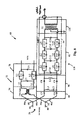
- FIG. 6 is a circuit diagram of one embodiment of a VDSL splitter device of the present invention configured for use with twisted pair wiring at the customer premise.
- FIG. 7 is a block diagram of one embodiment of a VDSL splitter device of the present invention configured for use with coax cable at the customer premise.
- FIG. 8 is a circuit diagram of one embodiment of a VDSL splitter device of the present invention configured for use with coax cable at the customer premise.
- FIG. 9 is a top view of a printed circuit board with electrical components as used in the POTS signal conditioning network and the voltage blocker and VDSL high-pass filter of one embodiment of the present invention.
- FIG. 10 is a view of a printed circuit board with electrical components as used in the VDSL low-pass filter of one embodiment of the present invention for connection to a twisted-pair VDSL network.
- FIG. 11 is a perspective view of one embodiment of a shielded VDSL low-pass filter for connection to a twisted-pair VDSL network.
- FIG. 12 is a view of a printed circuit board with electrical components as used in a VDSL low-pass filter of one embodiment of the present invention for connection to a coaxial cable.
- FIG. 13 is a perspective view of one embodiment of a shielded VDSL low-pass for connection to a coaxial cable.
- VDSL interface system 20 adapted to transmit VDSL signals across twisted pair wiring within a customer premise.
- VDSL interface system 20 includes VDSL splitter 22 , central office 24 , telephone network twisted pair wiring 26 , premise twisted pairs 28 and 30 , VDSL modem or multiplexor 32 , POTS devices 34 , and VDSL devices 36 .
- VDSL splitter 22 includes multi-frequency input port 38 , POTS output port 40 , and VDSL output port 42 .
- VDSL splitter 22 is connected to central office 24 through telephone network twisted pair wiring 26 .
- Twisted pair wiring 26 typically includes tip line 44 and ring line 46 .
- a multi-frequency signal that includes a low frequency POTS signal and a high-frequency VDSL signal is transmitted across twisted pair 26 and received by VDSL splitter 22 at input port 38 .
- VDSL splitter 22 separates the incoming multi-frequency signal into separate POTS and VDSL signals which are output at POTS output port 40 and VDSL output port 42 , respectively.
- VDSL splitter 22 is incorporated into a network interface device (NID) box module located within a telephone company NID box on the side of a building where telephone network twisted pair 26 enters the structure.
- NID network interface device
- VDSL splitter 22 may be located inside a premise.
- multiple VDSL splitters 22 may be located at each unit inside the building. More specifically, a VDSL splitter 22 may be located behind a wall plate in an inside wall of a unit within a multi-unit building.
- Premise twisted pair 28 which includes lines 48 and 50 , transmits the filtered POTS signal from output port 40 to POTS devices 34 .
- premise twisted pair 28 is a 100 ohm twisted pair of wires.
- POTS devices 34 include telephones, fax machines, and other devices that utilize low-frequency telephone signals.
- Premise twisted pair 30 which includes lines 52 and 54 , transmits the VDSL signal from output port 42 to VDSL modem 32 which decodes the VDSL signal for distribution over premise twisted pair 30 to VDSL devices 36 .
- VDSL devices 36 may include television set-top boxes, computers, and so on.
- premise twisted pair 30 is a Category 5 (Cat 5) 100 ohm twisted pair of wires.
- VDSL interface system 56 includes VDSL splitter 60 , central office 24 , telephone network twisted pair wiring 26 , premise twisted pair 28 , premise coax cable 58 , VDSL modem 62 , POTS devices 34 , and VDSL devices 36 .
- VDSL splitter 60 includes input port 38 , POTS output port 40 , and VDSL coax output port 64 .
- VDSL splitter 60 is connected to central office 24 through telephone network twisted pair wiring 26 .
- a multi-frequency signal that includes a low frequency POTS signal and a high-frequency VDSL signal is transmitted across twisted pair 26 and received by VDSL splitter 60 at input port 38 .
- VDSL splitter 60 separates the incoming multi-frequency signal into separate POTS and VDSL signals which are output at POTS output 40 and VDSL coax output 64 , respectively.
- VDSL splitter 60 is incorporated into a NID box located on the side of the premise, and VDSL coax output 64 may be an “F” connector.
- Premise twisted pair 28 which includes lines 48 and 50 , transmits the filtered POTS signal from output 40 to POTS devices 34 .
- premise twisted pair 28 is a 100 ohm twisted pair of wires.
- coax cable 58 transmits the VDSL signal from VDSL coax output 64 to VDSL modem 62 which decodes the VDSL signal for distribution back over coax cable 58 to VDSL devices 36 .
- VDSL splitter 22 in addition to input port 38 and output ports 40 and 42 , VDSL splitter 22 also includes connectors 68 and 70 , POTS signal conditioning network 72 and VDSL signal conditioning network 74 .
- POTS signal conditioning network 72 includes a common-mode choke 76 and POTS low-pass filter 78 .
- POTS low-pass filter 78 may be a multi-pole, high-order filter, with single or multiple filter stages.
- POTS low-pass filter 78 is a fourth-order filter that includes four stages, 80 through 86 .
- VDSL signal conditioning network 74 may include a voltage blocker 88 , a VDSL high-pass filter, a VDSL low-pass filter, or any combination thereof.
- VDSL signal conditioning network 74 includes voltage blocker 88 VDSL high-pass filter 90 , VDSL low-pass filter 92 , and electromagnetic shield 94 .
- VDSL high-pass filter 90 may be a multi-pole, or high-order filter, with multiple filter stages, and may be located between voltage blocker 88 and VDSL low-pass filter 92 .
- VDSL high-pass filter 90 is a third-order high-pass filter that includes, first stage 96 , second stage 98 , and third stage 100 .
- VDSL high-pass filter 90 may include fewer or more filter stages, or may be eliminated altogether from VDSL signal conditioning network 74 .
- VDSL low-pass filter 92 is a multi-pole, or high-order filter, with multiple filter stages.
- VDSL low-pass filter 92 is a seventh-order low-pass filter and includes seven stages, 102 through 114 .
- Other embodiments of VDSL low-pass filter 92 may include fewer or more filter stages, thereby affecting the frequency limits of the pass band, the roll-off, and other characteristics of VDSL low-pass filter 92 . For example, reducing and increasing the number of filter stages will respectively increase and decrease the rate of roll-off.
- VDSL high-pass filter 90 and VDSL low-pass filter 92 may be combined into a single bandpass filter, rather than separate low-pass and high-pass filters.
- VDSL high-pass filter 90 may not be included in VDSL signal conditioning network 74 .
- VDSL signal conditioning network 74 it may be desirable to allow all portions of the multi-frequency signal in the pass band of VDSL high-pass filter to be included in the VDSL signal at the VDSL output port.
- Electromagnetic shield 94 may encompass only VDSL low-pass filter 92 , as depicted in FIG. 3 , but may also encompass high-pass filter 90 , voltage blocker 88 , and other components.
- tip line 44 is tapped at connector 68 into signal lines 44 a and 44 b
- ring line 46 is tapped at connector 70 into signal lines 46 a and 46 b .
- the complete incoming multi-frequency signal received at input port 38 is routed to both POTS signal conditioning network 72 and VDSL signal conditioning network 74 .
- the frequency split of the incoming multi-frequency signal into its POTS and VDSL components is accomplished by passing the incoming multi-frequency signal through the distinctive and separate signal conditioning networks, POTS signal conditioning network 72 and VDSL signal conditioning network 74 .
- POTS signal conditioning network 72 With respect to the POTS signal, RF interference and the high-frequency portion of the incoming multi-frequency signal are removed by the POTS signal conditioning network 72 , leaving a resultant POTS low-frequency signal available at output port 40 .
- VDSL signal DC voltage is blocked, then those portions of the incoming multi-frequency signal above and below the VDSL range of frequencies are attenuated by VDSL signal conditioning network 74 .
- POTS signal conditioning network 72 allows the low-frequency portion of the signal to pass through with minimal attenuation. As illustrated in FIG. 4 , in one embodiment, POTS signal conditioning network 72 allows DC to 4 KHz portions of the incoming signal to pass through to the premise POTS network without signal attenuation, while greatly attenuating the higher-frequency VDSL signal. In other embodiments, the pass band characteristics of POTS signal conditioning network 72 may be adjusted to allow portions of the multi-frequency signal with frequencies above or below 4 kHz to be included in the POTS signal at the POTS output port.
- VDSL signal conditioning network 74 provides minimal attenuation to the 25 KHz to 8.5 MHz VDSL signal, yet provides high attenuation above 8.5 MHz.
- the pass band characteristics of VDSL high-pass filter 90 may be such that roll-off occurs above or below 8.5 MHZ, depending on the desired characteristics of the delivered VDSL signal.
- VDSL signals be as free from interference as possible and deliver the maximum data rate to VDSL devices 36 . This remains especially true of video signals. Interference may be introduced into the sensitive VDSL low-pass filter 92 of VDSL splitter 22 from the POTS circuit itself, and from outside sources, including sources within the customer premise.
- VDSL signal conditioning network 74 provides a critical attenuation of greater than 60 dB from 14.5 KHz to at least 25 KHz. The relatively steep 14.5 KHz low-pass filter roll-off seen from Points 2 to 3 is extremely important to signal performance.
- VDSL signal conditioning network 74 provides an attenuation of greater than 50 dB from 200 Hz to 7.5 KHz. A combination of these circuit performances greatly reduces VDSL data loss caused by transient signals created by POTS circuit operations such as on-hook, off-hook, and ringing instances.
- a signal attenuation of greater than 40 dB from 12 MHz to 28 MHz greatly reduces VDSL packet loss caused by a home network (HPNA) which may coexist on the same medium.
- HPNA home network
- the roll-off characteristics of VDSL high-pass filter 90 and the roll-off characteristics of VDSL low-pass filter 92 may not be symmetrical.
- the roll-off characteristics of VDSL high-pass filter 90 as illustrated in FIG. 5 exhibit a ⁇ 73 dB gain at 7 kHz, rising to an approximately ⁇ 1 dB gain at 22 kHz.
- VDSL low-pass filter 92 exhibits much steeper roll-off. For example, only ⁇ 2 dB of attenuation is seen at 8.5 mHz, yet at 12 mHz, the signal is attenuated by approximately ⁇ 51 dB.
- VDSL signal conditioning network 74 provides sharp roll-off with acceptable ripple at the high-frequency transition from pass band to stop band. At the same time, network 74 allows for less-sharp roll-off at the low-frequency edge of the VDSL spectrum at a significant component cost savings.
- FIG. 6 depicts one embodiment of an electrical circuit of VDSL splitter 22 , designed to achieve the specific performance as previously discussed, and as illustrated in FIGS. 4 and 5 .
- the circuit includes tip line 44 and ring line 46 , connectors 68 and 70 , POTS signal conditioning network 72 , VDSL signal conditioning network 74 , and premise twisted pairs 28 and 30 .
- POTS signal conditioning network 72 includes common mode choke 76 and POTS low-pass filter 78 .
- POTS low-pass filter 78 is a fourth-order, or four-stage, elliptical filter that includes mutual inductors L 1 and L 2 , and capacitors C 1 , C 2 , C 3 , and C 4 .
- mutual inductors L 1 and L 2 may be in the configuration of an EP-13 core.
- the incoming multi-frequency signal is received via signal lines 44 a and 46 a , and common mode choke 76 , connected to signal lines 44 a and 46 a , eliminates any radio-frequency (RF) noise on the incoming signal.
- the windings of common mode choke 76 are connected in series with the windings of mutual inductor L 1 .
- the windings of L 1 form POTS low-pass filter first stage 80 .
- Shunting capacitor C 1 is connected across the separate windings of mutual inductor L 1 and second mutual inductor L 2 .
- Shunting capacitor C 1 forms POTS low-pass filter second stage 82 .
- Capacitors C 2 and C 3 are connected in parallel with the windings of mutual inductor L 2 , and the parallel combinations of L 2 and capacitors C 2 and C 3 form POTS low-pass filter third stage 84 .
- Shunting capacitor C 4 is connected across mutual inductor L 2 and signal lines 44 a and 46 a , forming POTS low-pass filter fourth stage 86 .
- POTS low-pass filter 78 may have fewer or more stages, depending on desired performance considerations.
- the filtered POTS signal is output at output port 40 and lines 48 and 50 .
- POTS signal conditioning network 72 may include an inductor L 11 (not shown in FIG. 6 ) on signal line 44 a between POTS low-pass filter 78 and output 48 , and an inductor L 12 (not shown in FIG. 6 ) on signal line 44 b between filter 78 and output 28 .
- Inductors L 11 and L 12 are used to present a high impedance to any high frequencies on a phone line, for example, home phone networking signals.
- the component values of POTS low-pass filter 78 are selected to produce a sharp roll-off to 14.5 kHz as depicted in FIG. 4 , and at the same time, match required POTS input and output impedances.
- the impedance of POTS low-pass filter 78 matches an input impedance of 900 ohms, and an output impedance of 600 ohms.
- VDSL signal conditioning network 74 includes voltage blocker 88 , and VDSL high-pass filter 90 cascaded with VDSL low-pass filter 92 .
- VDSL low-pass filter 90 is surrounded by shield 94 .
- VDSL high-pass filter 90 may be a third-order, or three-stage, elliptical filter
- VDSL low-pass filter 92 may be a seventh-order, or seven-stage, elliptical filter.
- the input and output impedances of VDSL signal conditioning network 74 are selected to provide a 100 ohm input and output impedance match.
- voltage blocker 88 is comprised of a pair of capacitors C 5 and C 6 on signal lines 44 b and 46 b , respectively.
- the capacitors C 5 and C 6 serve to block incoming POTS DC voltage from the VDSL signal.
- VDSL high-pass filter 90 includes inductors L 3 and L 4 , along with capacitors C 7 , C 8 , and C 9 .
- the series connection of inductor L 3 and capacitor C 7 is coupled across signal lines 44 b and 46 b , forming VDSL high-pass filter first stage 96 .
- Blocking capacitors C 8 and C 9 are located in series in signal lines 44 b and 46 b , respectively, forming VDSL high-pass filter second stage 98 .
- Inductor L 4 is coupled across signal lines 44 b and 46 b to form VDSL high-pass filter third stage 100 , completing the third-order elliptical high-pass filter.
- VDSL high-pass filter 90 may have fewer or more stages, depending on desired performance considerations.
- VDSL low-pass filter 92 includes inductors L 5 through L 10 , and capacitors C 10 through C 19 , forming a seventh-order elliptical low-pass filter.
- shunting capacitors are coupled across signal lines 44 b and 46 b , followed by parallel LC combinations in series with each line. More specifically, shunting capacitor C 10 is coupled across signal lines 44 b and 46 b , followed by the parallel LC combination of L 5 and C 11 in signal line 44 b , and the parallel combination of L 6 and C 12 in signal line 46 b .
- C 13 is shunted across signal lines 44 b and 46 b , followed by L 7 in parallel with C 14 on signal line 44 b and L 8 in parallel with C 15 on signal line 46 b .
- C 16 is shunted across signal lines 44 b and 46 b , followed by L 9 in parallel with C 17 on signal line 44 b and L 10 in parallel with C 18 on signal line 46 b .
- C 19 is shunted across signal lines 44 b and 46 b.
- VDSL low-pass filter 92 is a seventh order filter with seven stages.
- C 10 , C 13 , C 16 , and C 19 form the first, third, fifth, and seventh stages, respectively.
- the parallel combination of L 5 and C 11 along with L 6 and C 12 form the second stage;
- L 7 and C 14 along with L 8 and C 15 form the fourth stage;
- L 9 and C 17 with L 10 and C 18 form the sixth stage.
- VDSL low-pass filter 92 may have fewer or more stages, depending on desired performance considerations.
- Electromagnetic shield 94 may be applied over all or part of VDSL signal conditioning network 74 . In one embodiment, shield 94 is applied only over VDSL low-pass filter 92 . Shield 94 may be made of metal or other suitable materials known to those skilled in the art. As previously mentioned, use of shield 94 prevents ingress of unwanted interference from sources within VDSL splitter 22 , as well as from outside sources
- VDSL splitter 60 is adapted to output VDSL signals at output port 64 to coax cable 58 within a customer premise.
- VDSL splitter 60 includes substantially all the components of VDSL splitter 22 , such as POTS signal conditioning network 72 , voltage blocker 88 , VDSL high-pass filter 90 , VDSL low-pass filter 92 , and shield 94 .
- VDSL signal conditioning network 118 of splitter 60 includes an impedance matching balun 120 connected to VDSL coax output port 64 .
- one embodiment of a circuit of VDSL splitter 60 includes the previously described POTS signal conditioning network 72 , voltage blocker 88 , VDSL high-pass filter 90 , VDSL low-pass filter 94 , and shield 94 .
- impedance matching balun 120 is connected to the output of VDSL low-pass filter 94 of VDSL signal conditioning network 118 .
- Balun 120 is appropriately wound to convert the 100 ohm balanced VDSL signal to a 75 ohm unbalanced VDSL signal for connection to coax cable 58 (see FIG. 2 ) at the customer premise. Balun 120 is also appropriately sized to accommodate the power transmitted through it without saturating. In the embodiment depicted in FIG. 8 , balun 120 includes a center-tap connected to ground on the 100 ohm side. This increases performance by creating a common-mode shunt which will couple any unwanted common-mode noise to ground. Shield 94 may encompass both VDSL low-pass filter 92 and balun 120 as depicted.
- VDSL splitter 60 yields less than 3 dB of signal loss from 25 kHz to 8.5 MHz. At the same time, VDSL splitter 60 is capable of transferring full-band VDSL signal levels of ⁇ 42 dBm/Hz without saturation or distortion.
- FIG. 9 provides a view of the various electrical components of POTS signal conditioning network 72 , voltage blocker 88 , and high-pass filter 90 , mounted atop a single circuit board 120 .
- Circuit board 120 also includes a number of spade terminals 122 for connecting board 120 and its components to other circuits and boards.
- VDSL low-pass filter 92 is located on a separate circuit board to facilitate shielding, in other embodiments, POTS signal conditioning network and the complete VDSL signal conditioning network 74 may be located on a single circuit board.
- POTS signal conditioning network 72 components 76 , L 1 , C 1 , L 2 , C 2 , C 3 , and C 4 are generally located across the bottom of circuit board 120 .
- Optional inductors L 11 and L 12 are included on board 120 as part of POTS signal conditioning network 72 .
- VDSL voltage blocker 88 and VDSL high-pass filter 90 are generally located across the top half of circuit board 120 .
- FIG. 10 depicts the various electrical components of VDSL low-pass filter 92 mounted to a top side 124 of a circuit board 126 .
- twisted pair of wires 130 connects VDSL high-pass filter 90 located on circuit board 120 to VDSL low-pass filter 92 located on circuit board 126 .
- Twisted pair 30 transmitting the filtered VDSL signal, is depicted connected to bottom side 128 of circuit board 126 .
- shield 94 is not included.
- FIGS. 9 and 10 comprise an unshielded embodiment of VDSL splitter 22 .
- FIG. 11 depicts shield 94 applied to the components of VDSL low-pass filter 92 mounted to circuit board 126 .
- the components depicted in FIGS. 9 and 11 comprise a shielded embodiment of VDSL splitter 22 .
- FIG. 12 depicts the electrical components of VDSL low-pass filter 92 , along with balun 120 and coax output 64 , mounted to a circuit board 126 .
- This configuration is designed for use in VDSL splitter 60 , that is adapted for connection to a coax cable 58 located at a customer premise.
- coax output 64 takes the form of an “F” connector.
- a shielded embodiment of this configuration is depicted in FIG. 13 .
- the components of POTS signal conditioning network 72 and VDSL signal conditioning network 74 may be mounted to a single circuit board, or combined into circuit boards of other devices, to form additional embodiments of VDSL splitter 22 or 60 .
Abstract
Description
Claims (42)
Priority Applications (1)
| Application Number | Priority Date | Filing Date | Title |
|---|---|---|---|
| US11/691,441 US8005206B1 (en) | 2007-03-15 | 2007-03-26 | VDSL splitter |
Applications Claiming Priority (2)
| Application Number | Priority Date | Filing Date | Title |
|---|---|---|---|
| US89501607P | 2007-03-15 | 2007-03-15 | |
| US11/691,441 US8005206B1 (en) | 2007-03-15 | 2007-03-26 | VDSL splitter |
Publications (1)
| Publication Number | Publication Date |
|---|---|
| US8005206B1 true US8005206B1 (en) | 2011-08-23 |
Family
ID=44455463
Family Applications (1)
| Application Number | Title | Priority Date | Filing Date |
|---|---|---|---|
| US11/691,441 Expired - Fee Related US8005206B1 (en) | 2007-03-15 | 2007-03-26 | VDSL splitter |
Country Status (1)
| Country | Link |
|---|---|
| US (1) | US8005206B1 (en) |
Cited By (6)
| Publication number | Priority date | Publication date | Assignee | Title |
|---|---|---|---|---|
| US20080279177A1 (en) * | 2007-05-09 | 2008-11-13 | Eyal Shlomot | Conjoined Telephony Communication System |
| US20140015622A1 (en) * | 2012-07-10 | 2014-01-16 | University Corporation For Atmospheric Research | Heat dissipating output network |
| US20140233562A1 (en) * | 2013-02-21 | 2014-08-21 | Inango Systems Ltd. | System and method for point-to-multipoint communication |
| DE102014206448A1 (en) * | 2014-04-03 | 2015-10-08 | Deutsche Telekom Ag | Method for the coaxial transmission of digital VDSL signals |
| CN109617756A (en) * | 2018-11-23 | 2019-04-12 | 上海神添实业有限公司 | A kind of intelligent test equipment and test method for high-speed digital subscriber line |
| US10727806B2 (en) * | 2017-03-15 | 2020-07-28 | Murata Manufacturing Co., Ltd. | Balun |
Citations (32)
| Publication number | Priority date | Publication date | Assignee | Title |
|---|---|---|---|---|
| US4003005A (en) | 1975-11-24 | 1977-01-11 | Electro Networks, Division Of Chloride, Inc. N. American Operations | Bidirectional constant impedance low pass/high pass filter circuit |
| US4443662A (en) | 1981-04-10 | 1984-04-17 | Northern Telecom Limited | Filters comprising reactive components, and a method of determining impedances thereof |
| US5495212A (en) | 1994-12-19 | 1996-02-27 | Bh Electronics, Inc. | Coupling device connecting an unbalanced signal line to a balanced signal line |
| US5757803A (en) * | 1995-11-27 | 1998-05-26 | Analog Devices, Inc. | Pots splitter assembly with improved transhybrid loss for digital subscriber loop transmission |
| US5930340A (en) | 1997-07-07 | 1999-07-27 | Advanced Micro Devices | Device and method for isolating voice and data signals on a common carrier |
| WO1999051019A1 (en) | 1998-04-01 | 1999-10-07 | Tyco Electronics Corporation | Access network with an integrated splitter |
| US6100772A (en) | 1998-11-16 | 2000-08-08 | Bh Electronics, Inc. | High frequency test balun with a capacitor across the output |
| US6115466A (en) | 1998-03-12 | 2000-09-05 | Westell Technologies, Inc. | Subscriber line system having a dual-mode filter for voice communications over a telephone line |
| US6118354A (en) | 1998-11-16 | 2000-09-12 | Bh Electronics, Inc. | High frequency splitter |
| US6137866A (en) | 1998-05-28 | 2000-10-24 | Siecor Operations, Llc | Indoor XDSL splitter assembly |
| US6144734A (en) | 1998-04-14 | 2000-11-07 | Siemens Information And Communication Networks, Inc. | Low-pass filters for splitterless pots and data transmission |
| WO2000070833A1 (en) | 1999-05-18 | 2000-11-23 | Qwest Communications International Inc. | Interface device having vdsl splitter and interference filter |
| US6285754B1 (en) | 2000-04-06 | 2001-09-04 | 2Wire, Inc. | Odd-order low-pass pots device microfilter |
| US6314102B1 (en) | 1997-07-10 | 2001-11-06 | Alcatel | Telecommunications system for providing both narrowband and broadband services to subscribers |
| US20020041676A1 (en) | 2000-02-22 | 2002-04-11 | Decramer John E. | POTS splitter |
| US6430288B1 (en) | 1999-10-14 | 2002-08-06 | Corning Cable Systems Llc | Phone line splitter assembly |
| US6574647B1 (en) | 1997-12-23 | 2003-06-03 | Ericsson Austria Ag | Filter arrangement |
| US20030112960A1 (en) * | 2001-12-14 | 2003-06-19 | Adc Dsl Systems, Inc. | Cascade low-pass filter to improve xDSL band attenuation for POTS splitter |
| KR100405173B1 (en) | 2003-08-05 | 2003-11-10 | Sun Myung Electro Telecom Co L | Method for winding coil of jack type splitter used for both adsl and vdsl |
| US6718020B2 (en) | 2002-04-12 | 2004-04-06 | Infineon Technologies Ag | Switchable POTS splitter |
| US6895089B2 (en) | 2001-12-14 | 2005-05-17 | Adc Dsl Systems, Inc. | Pots splitter with line impedance matching |
| US6980645B1 (en) | 1999-04-23 | 2005-12-27 | France Telecom Sa | Low-pass filtering device with integrated insulator and private installation comprising same |
| US6998964B2 (en) | 2003-05-30 | 2006-02-14 | Adc Dsl Systems, Inc. | Splitter |
| US7035380B1 (en) | 2000-02-16 | 2006-04-25 | Paradyne Corporation | Line sharing multipoint POTS splitter with intelligent termination |
| US7057486B2 (en) | 2001-11-14 | 2006-06-06 | Pulse Engineering, Inc. | Controlled induction device and method of manufacturing |
| US7068682B2 (en) | 2000-02-28 | 2006-06-27 | Qwest Communications International Inc. | Signal distribution within customer premises |
| US7103150B2 (en) | 2001-09-05 | 2006-09-05 | Adc Telecommunications, Inc. | Splitter card with integral test access |
| US7109837B2 (en) | 2003-03-18 | 2006-09-19 | Pulse Engineering, Inc. | Controlled inductance device and method |
| WO2006105534A2 (en) | 2005-03-31 | 2006-10-05 | Sbc Knowledge Ventures, L.P. | Vdsl splitter |
| US7164708B1 (en) | 1999-07-16 | 2007-01-16 | Infineon Technologies Ag | Line termination device for a telephone subscriber line |
| US20080074178A1 (en) * | 2006-09-22 | 2008-03-27 | Alcatel Lucent | MULTIPLE ORDER LOW PASS FILTER FOR AN xDSL SPLITTER IN A TELECOMMUNICATION SYSTEM |
| US20080151929A1 (en) * | 2006-12-20 | 2008-06-26 | Stefan Uhlemann | Communication circuitry, devices and methods |
-
2007
- 2007-03-26 US US11/691,441 patent/US8005206B1/en not_active Expired - Fee Related
Patent Citations (34)
| Publication number | Priority date | Publication date | Assignee | Title |
|---|---|---|---|---|
| US4003005A (en) | 1975-11-24 | 1977-01-11 | Electro Networks, Division Of Chloride, Inc. N. American Operations | Bidirectional constant impedance low pass/high pass filter circuit |
| US4443662A (en) | 1981-04-10 | 1984-04-17 | Northern Telecom Limited | Filters comprising reactive components, and a method of determining impedances thereof |
| US5495212A (en) | 1994-12-19 | 1996-02-27 | Bh Electronics, Inc. | Coupling device connecting an unbalanced signal line to a balanced signal line |
| US5757803A (en) * | 1995-11-27 | 1998-05-26 | Analog Devices, Inc. | Pots splitter assembly with improved transhybrid loss for digital subscriber loop transmission |
| US5930340A (en) | 1997-07-07 | 1999-07-27 | Advanced Micro Devices | Device and method for isolating voice and data signals on a common carrier |
| US6314102B1 (en) | 1997-07-10 | 2001-11-06 | Alcatel | Telecommunications system for providing both narrowband and broadband services to subscribers |
| US6574647B1 (en) | 1997-12-23 | 2003-06-03 | Ericsson Austria Ag | Filter arrangement |
| US6115466A (en) | 1998-03-12 | 2000-09-05 | Westell Technologies, Inc. | Subscriber line system having a dual-mode filter for voice communications over a telephone line |
| WO1999051019A1 (en) | 1998-04-01 | 1999-10-07 | Tyco Electronics Corporation | Access network with an integrated splitter |
| US6144734A (en) | 1998-04-14 | 2000-11-07 | Siemens Information And Communication Networks, Inc. | Low-pass filters for splitterless pots and data transmission |
| US6137866A (en) | 1998-05-28 | 2000-10-24 | Siecor Operations, Llc | Indoor XDSL splitter assembly |
| US6118354A (en) | 1998-11-16 | 2000-09-12 | Bh Electronics, Inc. | High frequency splitter |
| US6100772A (en) | 1998-11-16 | 2000-08-08 | Bh Electronics, Inc. | High frequency test balun with a capacitor across the output |
| US6980645B1 (en) | 1999-04-23 | 2005-12-27 | France Telecom Sa | Low-pass filtering device with integrated insulator and private installation comprising same |
| US6574236B1 (en) | 1999-05-18 | 2003-06-03 | Qwest Communications International Inc. | Interface device having VDSL splitter and interference filter |
| WO2000070833A1 (en) | 1999-05-18 | 2000-11-23 | Qwest Communications International Inc. | Interface device having vdsl splitter and interference filter |
| US7164708B1 (en) | 1999-07-16 | 2007-01-16 | Infineon Technologies Ag | Line termination device for a telephone subscriber line |
| US6430288B1 (en) | 1999-10-14 | 2002-08-06 | Corning Cable Systems Llc | Phone line splitter assembly |
| US7035380B1 (en) | 2000-02-16 | 2006-04-25 | Paradyne Corporation | Line sharing multipoint POTS splitter with intelligent termination |
| US20020041676A1 (en) | 2000-02-22 | 2002-04-11 | Decramer John E. | POTS splitter |
| US7068682B2 (en) | 2000-02-28 | 2006-06-27 | Qwest Communications International Inc. | Signal distribution within customer premises |
| US6285754B1 (en) | 2000-04-06 | 2001-09-04 | 2Wire, Inc. | Odd-order low-pass pots device microfilter |
| US7103150B2 (en) | 2001-09-05 | 2006-09-05 | Adc Telecommunications, Inc. | Splitter card with integral test access |
| US7057486B2 (en) | 2001-11-14 | 2006-06-06 | Pulse Engineering, Inc. | Controlled induction device and method of manufacturing |
| US20030112960A1 (en) * | 2001-12-14 | 2003-06-19 | Adc Dsl Systems, Inc. | Cascade low-pass filter to improve xDSL band attenuation for POTS splitter |
| US6895089B2 (en) | 2001-12-14 | 2005-05-17 | Adc Dsl Systems, Inc. | Pots splitter with line impedance matching |
| US6718020B2 (en) | 2002-04-12 | 2004-04-06 | Infineon Technologies Ag | Switchable POTS splitter |
| US7109837B2 (en) | 2003-03-18 | 2006-09-19 | Pulse Engineering, Inc. | Controlled inductance device and method |
| US6998964B2 (en) | 2003-05-30 | 2006-02-14 | Adc Dsl Systems, Inc. | Splitter |
| KR100405173B1 (en) | 2003-08-05 | 2003-11-10 | Sun Myung Electro Telecom Co L | Method for winding coil of jack type splitter used for both adsl and vdsl |
| WO2006105534A2 (en) | 2005-03-31 | 2006-10-05 | Sbc Knowledge Ventures, L.P. | Vdsl splitter |
| US20060225119A1 (en) * | 2005-03-31 | 2006-10-05 | Wollmershauser Steven M | VDSL splitter |
| US20080074178A1 (en) * | 2006-09-22 | 2008-03-27 | Alcatel Lucent | MULTIPLE ORDER LOW PASS FILTER FOR AN xDSL SPLITTER IN A TELECOMMUNICATION SYSTEM |
| US20080151929A1 (en) * | 2006-12-20 | 2008-06-26 | Stefan Uhlemann | Communication circuitry, devices and methods |
Cited By (6)
| Publication number | Priority date | Publication date | Assignee | Title |
|---|---|---|---|---|
| US20080279177A1 (en) * | 2007-05-09 | 2008-11-13 | Eyal Shlomot | Conjoined Telephony Communication System |
| US20140015622A1 (en) * | 2012-07-10 | 2014-01-16 | University Corporation For Atmospheric Research | Heat dissipating output network |
| US20140233562A1 (en) * | 2013-02-21 | 2014-08-21 | Inango Systems Ltd. | System and method for point-to-multipoint communication |
| DE102014206448A1 (en) * | 2014-04-03 | 2015-10-08 | Deutsche Telekom Ag | Method for the coaxial transmission of digital VDSL signals |
| US10727806B2 (en) * | 2017-03-15 | 2020-07-28 | Murata Manufacturing Co., Ltd. | Balun |
| CN109617756A (en) * | 2018-11-23 | 2019-04-12 | 上海神添实业有限公司 | A kind of intelligent test equipment and test method for high-speed digital subscriber line |
Similar Documents
| Publication | Publication Date | Title |
|---|---|---|
| EP1245084B1 (en) | Method and apparatus for rf common-mode noise rejection in a dsl receiver | |
| JP3449728B2 (en) | Up channel filter | |
| US8561125B2 (en) | Home network frequency conditioning device and method | |
| US6831975B1 (en) | Digital subscriber line (DSL) modem compatible with home networks | |
| JPH066359A (en) | Distribution network for radio-frequency broad- band signal and base-band signal and brige and tap therefor | |
| KR20040062783A (en) | Apparatus for reducing crosstalk interference due to tdsl based t-lan tranceiver | |
| US8005206B1 (en) | VDSL splitter | |
| US6298037B1 (en) | Network data filtering | |
| US20060029215A1 (en) | Lightning protection circuit | |
| US6359906B1 (en) | Providing digital services to telephone subscribers | |
| CA2571245C (en) | Amplifier for unshielded twisted pair wire signals | |
| US20060225119A1 (en) | VDSL splitter | |
| US6826278B2 (en) | Central office interface techniques for digital subscriber lines | |
| US8929468B1 (en) | Common-mode detection with magnetic bypass | |
| EP1675288B1 (en) | An arrangement for the transmission of a data signal in a cable television network | |
| US11949536B2 (en) | Transferring digital subscriber connection signals via a coaxial cable | |
| EP3245742B1 (en) | Systems and methods for enhanced high frequency power bias tee designs | |
| JP2008072301A (en) | In-phase signal reduction circuit | |
| EP1973272A1 (en) | Combiner with active balun for providing broadband internet access on catv networks | |
| US6826265B1 (en) | DSL-ready pots device and method | |
| US20020186824A1 (en) | Splitterless, transformerless, voice service independent ADSL interface | |
| WO2001006737A1 (en) | Odd-order low-pass pots device filter | |
| EP1406384B1 (en) | Reverse gain saving broadband RF couplers | |
| JP2002532978A (en) | Telecommunications system and connection equipment used therein | |
| EP1898663B1 (en) | A filter device for passing telephony signals |
Legal Events
| Date | Code | Title | Description |
|---|---|---|---|
| AS | Assignment |
Owner name: BH ELECTRONICS, INC., MINNESOTA Free format text: ASSIGNMENT OF ASSIGNORS INTEREST;ASSIGNORS:DOOSE, NATHAN G.;DECRAMER, JOHN E.;REEL/FRAME:021623/0753 Effective date: 20080926 |
|
| ZAAA | Notice of allowance and fees due |
Free format text: ORIGINAL CODE: NOA |
|
| ZAAB | Notice of allowance mailed |
Free format text: ORIGINAL CODE: MN/=. |
|
| ZAAA | Notice of allowance and fees due |
Free format text: ORIGINAL CODE: NOA |
|
| STCF | Information on status: patent grant |
Free format text: PATENTED CASE |
|
| CC | Certificate of correction | ||
| FPAY | Fee payment |
Year of fee payment: 4 |
|
| MAFP | Maintenance fee payment |
Free format text: PAYMENT OF MAINTENANCE FEE, 8TH YR, SMALL ENTITY (ORIGINAL EVENT CODE: M2552); ENTITY STATUS OF PATENT OWNER: SMALL ENTITY Year of fee payment: 8 |
|
| FEPP | Fee payment procedure |
Free format text: MAINTENANCE FEE REMINDER MAILED (ORIGINAL EVENT CODE: REM.); ENTITY STATUS OF PATENT OWNER: SMALL ENTITY |
|
| LAPS | Lapse for failure to pay maintenance fees |
Free format text: PATENT EXPIRED FOR FAILURE TO PAY MAINTENANCE FEES (ORIGINAL EVENT CODE: EXP.); ENTITY STATUS OF PATENT OWNER: SMALL ENTITY |
|
| STCH | Information on status: patent discontinuation |
Free format text: PATENT EXPIRED DUE TO NONPAYMENT OF MAINTENANCE FEES UNDER 37 CFR 1.362 |
|
| FP | Lapsed due to failure to pay maintenance fee |
Effective date: 20230823 |