US8002410B2 - User-proposed entry field(s) for customized data analysis/presentation - Google Patents
User-proposed entry field(s) for customized data analysis/presentation Download PDFInfo
- Publication number
- US8002410B2 US8002410B2 US12/643,945 US64394509A US8002410B2 US 8002410 B2 US8002410 B2 US 8002410B2 US 64394509 A US64394509 A US 64394509A US 8002410 B2 US8002410 B2 US 8002410B2
- Authority
- US
- United States
- Prior art keywords
- wavefront
- user
- data values
- aberration
- raw
- Prior art date
- Legal status (The legal status is an assumption and is not a legal conclusion. Google has not performed a legal analysis and makes no representation as to the accuracy of the status listed.)
- Expired - Fee Related
Links
- 238000007405 data analysis Methods 0.000 title 1
- 238000000034 method Methods 0.000 claims abstract description 43
- 230000004075 alteration Effects 0.000 claims description 43
- 230000008569 process Effects 0.000 claims description 29
- 238000005259 measurement Methods 0.000 claims description 26
- 208000014733 refractive error Diseases 0.000 claims description 18
- 206010010071 Coma Diseases 0.000 claims description 4
- 235000004035 Cryptotaenia japonica Nutrition 0.000 claims description 3
- 102000007641 Trefoil Factors Human genes 0.000 claims description 3
- 235000015724 Trifolium pratense Nutrition 0.000 claims description 3
- 206010002945 Aphakia Diseases 0.000 claims description 2
- 238000004458 analytical method Methods 0.000 claims description 2
- 230000006870 function Effects 0.000 description 18
- 230000004308 accommodation Effects 0.000 description 11
- 230000008859 change Effects 0.000 description 11
- 238000012937 correction Methods 0.000 description 11
- 230000004438 eyesight Effects 0.000 description 8
- 238000001514 detection method Methods 0.000 description 7
- 238000010586 diagram Methods 0.000 description 7
- 230000003287 optical effect Effects 0.000 description 6
- 230000010287 polarization Effects 0.000 description 6
- 238000012545 processing Methods 0.000 description 5
- 230000004304 visual acuity Effects 0.000 description 5
- 210000001525 retina Anatomy 0.000 description 4
- 230000007246 mechanism Effects 0.000 description 3
- 238000012546 transfer Methods 0.000 description 3
- 230000002350 accommodative effect Effects 0.000 description 2
- 238000013459 approach Methods 0.000 description 2
- 238000000149 argon plasma sintering Methods 0.000 description 2
- 230000001419 dependent effect Effects 0.000 description 2
- 239000004973 liquid crystal related substance Substances 0.000 description 2
- 238000005070 sampling Methods 0.000 description 2
- 230000000007 visual effect Effects 0.000 description 2
- 230000004913 activation Effects 0.000 description 1
- 230000003044 adaptive effect Effects 0.000 description 1
- 201000009310 astigmatism Diseases 0.000 description 1
- 239000007795 chemical reaction product Substances 0.000 description 1
- 238000004891 communication Methods 0.000 description 1
- 230000001447 compensatory effect Effects 0.000 description 1
- 230000008878 coupling Effects 0.000 description 1
- 238000010168 coupling process Methods 0.000 description 1
- 238000005859 coupling reaction Methods 0.000 description 1
- 238000013480 data collection Methods 0.000 description 1
- 238000013461 design Methods 0.000 description 1
- 210000003128 head Anatomy 0.000 description 1
- 238000003331 infrared imaging Methods 0.000 description 1
- 230000000977 initiatory effect Effects 0.000 description 1
- 239000007788 liquid Substances 0.000 description 1
- 238000012986 modification Methods 0.000 description 1
- 230000004048 modification Effects 0.000 description 1
- 238000003333 near-infrared imaging Methods 0.000 description 1
- 238000012634 optical imaging Methods 0.000 description 1
- 230000002093 peripheral effect Effects 0.000 description 1
- 230000005043 peripheral vision Effects 0.000 description 1
- 238000011112 process operation Methods 0.000 description 1
- 239000000047 product Substances 0.000 description 1
- 238000012552 review Methods 0.000 description 1
- 230000035945 sensitivity Effects 0.000 description 1
- 239000007787 solid Substances 0.000 description 1
- 238000010561 standard procedure Methods 0.000 description 1
- 238000001356 surgical procedure Methods 0.000 description 1
Images


Classifications
-
- A—HUMAN NECESSITIES
- A61—MEDICAL OR VETERINARY SCIENCE; HYGIENE
- A61B—DIAGNOSIS; SURGERY; IDENTIFICATION
- A61B3/00—Apparatus for testing the eyes; Instruments for examining the eyes
- A61B3/10—Objective types, i.e. instruments for examining the eyes independent of the patients' perceptions or reactions
- A61B3/1015—Objective types, i.e. instruments for examining the eyes independent of the patients' perceptions or reactions for wavefront analysis
-
- A—HUMAN NECESSITIES
- A61—MEDICAL OR VETERINARY SCIENCE; HYGIENE
- A61B—DIAGNOSIS; SURGERY; IDENTIFICATION
- A61B3/00—Apparatus for testing the eyes; Instruments for examining the eyes
- A61B3/0016—Operational features thereof
- A61B3/0025—Operational features thereof characterised by electronic signal processing, e.g. eye models
-
- A—HUMAN NECESSITIES
- A61—MEDICAL OR VETERINARY SCIENCE; HYGIENE
- A61B—DIAGNOSIS; SURGERY; IDENTIFICATION
- A61B3/00—Apparatus for testing the eyes; Instruments for examining the eyes
- A61B3/0016—Operational features thereof
- A61B3/0041—Operational features thereof characterised by display arrangements
-
- A—HUMAN NECESSITIES
- A61—MEDICAL OR VETERINARY SCIENCE; HYGIENE
- A61B—DIAGNOSIS; SURGERY; IDENTIFICATION
- A61B3/00—Apparatus for testing the eyes; Instruments for examining the eyes
- A61B3/0091—Fixation targets for viewing direction
-
- A—HUMAN NECESSITIES
- A61—MEDICAL OR VETERINARY SCIENCE; HYGIENE
- A61B—DIAGNOSIS; SURGERY; IDENTIFICATION
- A61B3/00—Apparatus for testing the eyes; Instruments for examining the eyes
- A61B3/02—Subjective types, i.e. testing apparatus requiring the active assistance of the patient
- A61B3/028—Subjective types, i.e. testing apparatus requiring the active assistance of the patient for testing visual acuity; for determination of refraction, e.g. phoropters
- A61B3/036—Subjective types, i.e. testing apparatus requiring the active assistance of the patient for testing visual acuity; for determination of refraction, e.g. phoropters for testing astigmatism
-
- A—HUMAN NECESSITIES
- A61—MEDICAL OR VETERINARY SCIENCE; HYGIENE
- A61B—DIAGNOSIS; SURGERY; IDENTIFICATION
- A61B3/00—Apparatus for testing the eyes; Instruments for examining the eyes
- A61B3/10—Objective types, i.e. instruments for examining the eyes independent of the patients' perceptions or reactions
- A61B3/103—Objective types, i.e. instruments for examining the eyes independent of the patients' perceptions or reactions for determining refraction, e.g. refractometers, skiascopes
- A61B3/1035—Objective types, i.e. instruments for examining the eyes independent of the patients' perceptions or reactions for determining refraction, e.g. refractometers, skiascopes for measuring astigmatism
-
- A—HUMAN NECESSITIES
- A61—MEDICAL OR VETERINARY SCIENCE; HYGIENE
- A61B—DIAGNOSIS; SURGERY; IDENTIFICATION
- A61B3/00—Apparatus for testing the eyes; Instruments for examining the eyes
- A61B3/10—Objective types, i.e. instruments for examining the eyes independent of the patients' perceptions or reactions
- A61B3/13—Ophthalmic microscopes
-
- A—HUMAN NECESSITIES
- A61—MEDICAL OR VETERINARY SCIENCE; HYGIENE
- A61B—DIAGNOSIS; SURGERY; IDENTIFICATION
- A61B3/00—Apparatus for testing the eyes; Instruments for examining the eyes
- A61B3/10—Objective types, i.e. instruments for examining the eyes independent of the patients' perceptions or reactions
- A61B3/14—Arrangements specially adapted for eye photography
-
- A—HUMAN NECESSITIES
- A61—MEDICAL OR VETERINARY SCIENCE; HYGIENE
- A61B—DIAGNOSIS; SURGERY; IDENTIFICATION
- A61B5/00—Measuring for diagnostic purposes; Identification of persons
- A61B5/74—Details of notification to user or communication with user or patient ; user input means
- A61B5/7405—Details of notification to user or communication with user or patient ; user input means using sound
- A61B5/7415—Sound rendering of measured values, e.g. by pitch or volume variation
-
- A—HUMAN NECESSITIES
- A61—MEDICAL OR VETERINARY SCIENCE; HYGIENE
- A61B—DIAGNOSIS; SURGERY; IDENTIFICATION
- A61B90/00—Instruments, implements or accessories specially adapted for surgery or diagnosis and not covered by any of the groups A61B1/00 - A61B50/00, e.g. for luxation treatment or for protecting wound edges
- A61B90/20—Surgical microscopes characterised by non-optical aspects
-
- G—PHYSICS
- G01—MEASURING; TESTING
- G01J—MEASUREMENT OF INTENSITY, VELOCITY, SPECTRAL CONTENT, POLARISATION, PHASE OR PULSE CHARACTERISTICS OF INFRARED, VISIBLE OR ULTRAVIOLET LIGHT; COLORIMETRY; RADIATION PYROMETRY
- G01J9/00—Measuring optical phase difference; Determining degree of coherence; Measuring optical wavelength
-
- G—PHYSICS
- G01—MEASURING; TESTING
- G01J—MEASUREMENT OF INTENSITY, VELOCITY, SPECTRAL CONTENT, POLARISATION, PHASE OR PULSE CHARACTERISTICS OF INFRARED, VISIBLE OR ULTRAVIOLET LIGHT; COLORIMETRY; RADIATION PYROMETRY
- G01J3/00—Spectrometry; Spectrophotometry; Monochromators; Measuring colours
- G01J3/02—Details
- G01J3/06—Scanning arrangements arrangements for order-selection
- G01J2003/064—Use of other elements for scan, e.g. mirror, fixed grating
Definitions
- One or more embodiments of the present invention relate generally to data manipulation and presentation.
- the invention relates to user interface of a device which allows the individual user to customize the manipulation of data collected or captured by a device.
- measurement devices are provided to the end user with built-in control for data collection, processing and presentation or display.
- the end users thus do not have the freedom to manipulate the data to their preference.
- one embodiment of the present invention satisfy one or more of the above-identified need(s) in the art.
- one embodiment of the present invention is a method for allowing the end user to choose the way of customizing the manipulation of the data captured from a measurement device.
- FIG. 1 depicts a block diagram of an example embodiment
- FIG. 2 shows a block diagram of the steps involved in one embodiment of presently disclosed method
- FIGS. 3 and 4 depict screen shots of user output from an embodiment
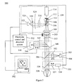
- FIG. 5 shows a schematic diagram of one embodiment in which a dynamic defocus offsetting device is used to offset spherical refractive error of the wavefront from an eye
- FIG. 6 shows a block diagram of a typical electronic control and detection system that is illustrated in FIG. 5 .
- the end-user of a measurement device such as a wavefront sensor for eye refractive error or aberration is provided with freedom of manipulating the devices' resultant datum or data to a form, format, transfer function, application, expression, output, and or an algorithm that he/she so chooses.
- FIG. 1 is a block diagram of an example embodiment.
- a measurement device 110 is coupled to a device interface 111 including controller 112 including a processor 114 , a memory 116 , a device interface 118 , and I/O interface 120 and an internal bus 122 coupling the various components of the controller.
- a user-input device 124 such as a keyboard or mouse, and an output device 126 , such as a display are coupled to the I/O interface 120 .
- the measurement device 110 is coupled to the device interface 118 (or alternatively to the I/O interface 120 ) and provides as raw data the results from a measurement to the controller 112 .
- the purpose is to not limit the device's manipulation of the data to that of the manufacturer, but to allow greater freedom for customization by the individual user for their preference, which can potentially change with different applications of the device. It solves the varying and unique needs of the end users to control what processes they want to be applied (specific algorithms, filters, and analyses, for example) to the data and to be displayed to meet their varying needs. These processes can be applied real time, saved off for later use, sent over the intranet or internet, for examples. They can occur simultaneously or discretely per the user's choice.
- FIG. 2 shows an example flow diagram of the steps. In an example embodiment these steps would be implemented by the controller when executing a program stored in the memory. The raw data supplied by the measurement device would also be stored in the memory.
- the device's application/process would initiate or run.
- the “Machine” asks the user if they would like to alter the default or previous algorithm(s) used for displaying or representing or storing or transmitting resultant information from the collected or acquired data.
- the default or previous algorithm(s) can be that of a wavefront sensor for eye refractive error or aberration measurement(s).
- step 220 the machine may either use the default or previously used algorithm(s) or ask the user to select from a list of predefined algorithms.
- step 222 the machine functions as intended, while providing the resultant data per the user's selection as shown by step 222 , which is followed by the end step 230 .
- step 206 the machine initiates a user entry process as shown by step 206 .
- the machine allows the user to enter in the process or algorithm.
- the machine assigns the raw datum fields to a particular function, functions, or algorithms.
- step 212 the function(s) or algorithms provide the user their desired assessment/alteration of the data and output it in a manner of various forms before the end step 230 .
- these algorithms could be entered real time, for example with a keyboard, or imported from another medium.
- the machine could also provide the user a set of predetermined algorithms or processes that could be applied separately or in combination with the data from the machine. For example there could be a low-pass filter algorithm/module and a polar coordinate transfer function/module. The user could select to have the data converted to polar coordinates then low-pass filtered.
- the user could also be prompted by the machine to determine the desired output method or methods for the above. For example, the user could opt for a graphical display, audio, or numeric, or all.
- the output data could also be exported to another application or machine/device to affect its functionality or not, or as a combination of data usage/storage.
- the machine could present the predefined algorithms/applications such that the user could be prompted to change the currently applied algorithm/application to a new one real time, without the need to pause or stop the machine's current process(es).
- the user could be prompted to customize the manner in which the resultant data, raw or processed, is to be presented.
- the machine could prompt the user to select a graphical display, the type of display and the data limits displayed. Alternatively the user could select that the data be displayed, processed or raw, with or without a graphical component.
- the data/datum from a device that is provided either from or through a microprocessor, over a communication link, or displayed can be input into a user created and selected process or processes.
- the user would have the ability to direct specific data or datum into a specific input (independent variable) field of their creation(s).
- IOL intraocular lens
- FIGS. 3 and 4 are example screen shots for the above describe process.
- the assignment of the raw data to variables is defined and the user is prompted to enter an algorithm.
- FIG. 4 the data values assigned to the variables and resultant value are displayed.
- the present method provides the user great flexibility to fully utilize the processors' and device's capability and to maximize the end product for their use.
- Embodiments can be autorefractors or wavefront sensors where the device's data can be used for a multitude of outcomes/uses such as prescriptions, 3 or 2 dimensional graphs, averaged; ophthalmic cameras where the photographic data can be processed through a custom algorithm such as a FFT; a Pulse oximeter output where the beat-to-beat data could be processed for unique events.
- the example embodiment can be implemented manually, orally, scripted, and/or provided in a separate application/process to the primary process. This process can occur prior to, during, or after the use of the machine/device. Thereby allowing the user the flexibility to plan the desired outcome(s) prior to initiating the use of the machine/device; adjust the outcomes real time during the use of the machine/device; or post use in assessing the collected data using a variation of processes.
- the scripting of the application can occur discretely a single fixed application or as a multitude of applications that could occur sequentially, randomly, or for a preferred application or utilization of the machine/device or process.
- the raw measurement data includes, for example, spherical refractive error, cylindrical refractive error, and high-order aberrations such as coma, trefoil, and spherical aberrations.
- the measurement device will now be described.
- FIG. 5 shows one embodiment of a dynamic wavefront sensing system in which a defocus offset device is used to offset the spherical refractive error component of the wavefront from an eye.
- a sequential wavefront sensor 528 has a first lens 504 that focuses a linearly polarized input beam of light having a wavefront 502 .
- the focusing beam travels through a polarization beam splitter (PBS) 506 , which is arranged in such a manner that its pass-through polarization direction is aligned with the polarization direction of the incoming beam.
- PBS polarization beam splitter
- a quarter-wave plate 508 is placed behind the PBS 506 with fast axis oriented so that a circularly polarized beam is emerged after passing through the quarter-wave plate 508 .
- a pinhole 510 is placed behind the quarter wave plate 508 and right in front of the scanning mirror 512 to serve the purpose of rejecting the light not directly coming from interested wavefront of the light beam.
- the input convergent beam after passing through the pinhole 510 , is focused on the reflective surface of a tilted scanning mirror 512 , which is mounted on the shaft of a motor 514 .
- the light beam reflected by the mirror is divergent, with its beam central chief ray changed to a direction that is dependent on the tilting angle of the scan mirror 512 and the rotational position of the motor 514 . It is expected that the reflected beam is still circularly polarized, but the circular polarization rotation direction will be changed from left hand to right hand or from right hand to left hand.
- the beam upon passing through the quarter-wave plate 508 for a second time on its return path, the beam becomes linearly polarized again, but with its polarization direction rotated to an orthogonal direction with respect to that of the original incoming beam. Therefore, at the polarization beam splitter 506 , the returned beam will be mostly reflected to the left as shown by the dashed light rays in FIG. 5 .
- a second lens 516 is placed on the left next to the PBS 506 to collimate the reflected divergent beam and to produce a replica of the original input wavefront. Due to the tilting of the scan mirror, the replicated wavefront is transversely shifted.
- An aperture 518 is placed behind the second lens 516 and right in front of the sub-wavefront focusing lens 520 to select a small portion of the replicated wavefront.
- the sub-wavefront focusing lens 520 focuses the selected sub-wavefront onto a position sensing device 522 , which is used to determine the centroid of the focused light spot generated from the sequentially selected sub-wavefronts.
- the amount of radial and azimuthal shift of the replicated wavefront can be controlled such that any potion of the replicated wavefront can be selected to pass through the aperture 518 in a sequential way.
- the overall wavefront of the original incoming beam can be characterized as for the case of a standard Hartmann-Shack wave-front sensor with the exception that the centroid of each sub-wavefront is now obtained in a sequential rather than a parallel manner.
- an annular section of the wavefront 502 is sequentially scanned.
- the radius of the annular section can be changed by changing the tilt of the scanning mirror.
- the light source module 535 comprising the light source 534 , the collimating lens 537 and the beam directing element 536 , is used to direct a narrow beam of light onto the retina of a patient eye 538 .
- the infrared imaging module 583 can be used to monitor the position of the fovea and also to align and register the eye.
- the internal fixation and visual acuity projection module 542 as shown in FIG. 5 can comprise a micro display 544 , a variable focus lens 546 and a beam directing element 548 , and serve the function of changing the accommodation of the patient's eye as well as checking the patient's visual acuity.
- the internal fixation/visual acuity projection module can also be used to change the accommodation of the patient's eye with wavefront measurements also done for the whole accommodation range.
- the axis of fixation may not change which means proper patient alignment, the actual visual axis or center may vary, indicating a kind of pseudo accommodation or non-symmetric visual correction.
- the wavefront sensor can record the variation and determine accommodative correction.
- the internal fixation/visual acuity projection module can also be used to guide the patient to look off-axis so that the incident light beam can be guided to land on different positions of the retina rather than at the fovea region.
- This can be achieved by turning a certain pixel or group of pixels of the micro display 544 on and as a result, the eye will be directed to fixate on the “on” pixel(s), making it possible to capture the eye aberration wavefront for both the center and the peripheral light scattering locations.
- wavefront aberrations can be measured as a function of the landing position of the incident light beam and therefore a 2D array of wavefront aberrations for light scattered from different locations on the retina can be generated.
- Such a 2D array of wavefront measurements will provide a vision correction practitioner with additional valuable information in addition to a conventional eye aberration wavefront measurement resulting from only a central light scattering location. This will further optimize aberration correction prescriptions in the sense that in addition to central vision, peripheral vision can also be optimized.
- active defocus offsetting is achieved by changing the effective focal length or the spherical refractive power of a lens or a lens combination 505 disposed in the optical path in front of a wavefront sensor 528 .
- the change of the effective focal length can be calibrated to indicate the correction in diopters (for example) required to change the actual wavefront returned from the retina to a plane wave.
- This correction in diopters is the refractive prescription for correcting the vision of a patient. The procedures for obtaining this prescription for spherical and astigmatic aberrations are described in detail below.
- a dynamic defocus offsetting element 505 is arranged in the light path.
- Previous embodiments only mentioned the compensation or defocus nulling function if such an element is used.
- the defocus offsetting element 505 in addition to the compensation or nulling function, also provides active off-setting or partial cancellation of the spherical refractive error component in either the positive or negative direction to make the wavefront more or less spherically divergent or convergent and the active offset is at the disposal of the refractive surgeon or controlled by a built-in algorithm according to the real time display and/or feedback of the wavefront measurement.
- One aspect of the embodiment is to use the defocus offset device to partially compensate for any relatively large spherical refractive error so that the remaining spherical and cylindrical refractive errors and other higher order aberrations all fall within the measurement dynamic range of the wavefront sensor.
- the variable focal length lens is functioning as an optical component that can also substantially increase the measurement dynamic range of the combined wavefront sensing system.
- Another aspect of the embodiment is to scan the defocus offset within the wavefront measurement range with or without the accommodation change of the eye over the accommodation range so that a better and more precise measurement of the eye refractive errors can be obtained.
- the defocus offsetting device described in FIG. 5 can include a set of configured lenses to allow a shifting of the focal range along the return beam optical axis.
- the position and axial spacing of these lenses provides an offset that can actively remove or adjust the spherical refractive error component of the transmitted beam.
- This active focusing alters the divergence or convergence of the beam to “fit” or allow matching of the beam focusing properties in order to accentuate other aberration properties such as the appearance of the elliptically shaped beam pattern indicating an astigmatic condition.
- This “fitting process” does change the spherical power of such a beam with an exact knowledge of the amount of compensatory focal change.
- the first order linear focal shift introduced by the offsetting active lens(es) does(do) not alter the properties of the other inherent aberrations, it serves the basic purpose of highlighting and emphasizing the underlying higher order aberrations that are present.
- the sensitivity to detection of the existing higher order aberrations increase with more exact fitting location as the spherical refractive error component of the aberration is “matched” or “fitted” allowing better appreciation and detection of wavefront changes imposed by the lesser slope values which can be masked by large spherical wavefront slope values.
- the defocus offsetting element in FIG. 5
- other focus variable optical element can be used, including liquid or solid focus variable lenses, voice coil or motor driven movable lens(es), liquid crystal lens(es), acousto-optic lens(es), deformable mirror(s) and diaphragm(s).
- the position of the defocus offsetting element does not need to be right in front of the wavefront sensor and can be anywhere along the optical path as long as it serves the function of offsetting the defocus of the wavefront.
- the defocus offsetting element can be designed together with other optical element(s) inside the wavefront sensor 528 .
- sequential wavefront sensor 528 can be combined with the front focusing lens 504 of the sequential wavefront sensor 528 .
- a real time sequential wavefront can be made with a small form factor and thus be integrated into a large number of optical imaging or measurement systems, such as an eye refractive surgical microscope.
- optical imaging or measurement systems such as an eye refractive surgical microscope.
- a sequential wavefront sensor 528 has been illustrated in FIG. 5
- other types of wavefront sensors can also be used as long as it can provide wavefront measurement, including Hartmann-Shack, Talbot-Moire, Tscherning, Ray-tracing, phase diversity and interferometric wavefront sensors.
- the electronic control and detection system 532 coordinates the activation of all active elements, including the defocus offsetting device 505 , the focusing lens 582 of the near infrared imaging camera 584 , the accommodation changing element 546 of the internal fixation/visual acuity projector 542 and others.
- FIG. 6 is a detailed block diagram of an example embodiment the electronic control and detection system 532 .
- a printed circuit board (PCB) 600 includes a micro-controller 601 having a memory 602 for storing program code and data, and a processing unit 604 for executing the program code and processing the data.
- the microcontroller has an I/O interface (indicated by arrows) 605 coupled to various control modules 606 to 618 .
- the control modules are interfaced with the various components of the deterministic dynamic wavefront sensing system depicted in FIG. 5 using standard techniques.
- the PCB 600 also includes a host-side interface 620 for interfacing with the host computer and display module 592 and a user interface 622 for interfacing with a user interface device such as a foot pedal 624 .
- the foot pedal can be configured to allow a surgeon to “zoom in” or “zoom out” by controlling the position of the defocusing mechanism.
- the memory 602 is configured to store programs executed to perform the algorithms described below to control the deterministic dynamic wavefront sensing system depicted in FIG. 5 .
- the various modules depicted in FIG. 6 may be implemented as discrete parts or integrated onto ASICs or other programmable devices.
- the microcontroller 601 can send control signal to a scanning mirror controller connected 606 to a scanning mirror driver to drive the scanning mirror 514 and can send control signals to a light source controller 608 to turn the light source 534 on and off. Further, the microcontroller can receive signals from the quadrant detector 522 as shown in FIG. 5 through a front-end amplifier and an A/D converter 610 . In addition, the microcontroller can also control the NIR camera focusing lens 582 through a focus lens controller 612 . One key function of the microcontroller is to offset the defocus of the defocus offset device 505 through a defocus offset controller 614 .
- microcontroller can provide different the accommodation of the patient eye by controlling the accommodation changing element 546 through an internal fixation controller 616 , and changing the subwavefront sampling aperture size of the variable aperture device 518 through a variable aperture controller 618 .
- the function of the electronic control and detection sub-system can be provided by a dedicated micro-processor or a computer or other electronic processing means and therefore, the electronic control and detection system 532 shown in FIG. 5 should only be considered as an optional component but not as an absolutely needed item for the apparatus.
- the display module 592 shown in FIG. 5 is included because it can be viewed directly by a refractive surgeon during a vision correction procedure to guide him/her in selecting the desired defocus offset and in optimizing the vision correction outcome. It should, however, be noted that the display module 592 in FIG. 5 should be interpreted broadly as a real time feedback means.
- an approach to implement the display of the real time wavefront measurement is to incorporate a micro display inside the surgical microscope so that the wavefront measurement result can be overlaid onto the image of the patient's eye formed by the surgical microscope and presented to the refractive surgeon directly. In doing so, the surgeon does not need to move his/her head away from the binocular of the surgical microscope.
- the wavefront can be sampled according to a sampling pattern while offsetting some lower order aberrations so that information on some particular higher order wavefront aberrations can be clearly highlighted or vice versa.
- higher order aberration (HOA) content such as coma, which is a very prevalent HOA that surgeons are becoming familiar with and have techniques to address surgically, can be highlighted and displayed in a format easily understandable by clinical practitioners.
- the micro-controller 601 further executes a program stored, for example, in memory 602 to implement the steps described above with reference to FIG. 2 .
- the user provides input and receives output through the attached host computer and display module 592 .
- the user input can be directly provided to the micro-controller 601 through a connected user-input device and the output coupled to an output device.
- the micro-controller 601 would output the raw data to the host computer and display module 592 and the processing described above with reference to FIG. 2 would be performed by the host computer and display module 592 .
Abstract
Description
Claims (14)
Priority Applications (3)
| Application Number | Priority Date | Filing Date | Title |
|---|---|---|---|
| US12/643,945 US8002410B2 (en) | 2006-01-20 | 2009-12-21 | User-proposed entry field(s) for customized data analysis/presentation |
| US13/034,648 US8820929B2 (en) | 2006-01-20 | 2011-02-24 | Real-time measurement/display/record/playback of wavefront data for use in vision correction procedures |
| US13/198,442 US8356900B2 (en) | 2006-01-20 | 2011-08-04 | Large diopter range real time sequential wavefront sensor |
Applications Claiming Priority (4)
| Application Number | Priority Date | Filing Date | Title |
|---|---|---|---|
| US11/335,980 US7445335B2 (en) | 2006-01-20 | 2006-01-20 | Sequential wavefront sensor |
| US11/761,890 US7815310B2 (en) | 2006-01-20 | 2007-06-12 | Adaptive sequential wavefront sensor and its applications |
| US12/605,219 US8100530B2 (en) | 2006-01-20 | 2009-10-23 | Optimizing vision correction procedures |
| US12/643,945 US8002410B2 (en) | 2006-01-20 | 2009-12-21 | User-proposed entry field(s) for customized data analysis/presentation |
Related Parent Applications (1)
| Application Number | Title | Priority Date | Filing Date |
|---|---|---|---|
| US12/605,219 Continuation-In-Part US8100530B2 (en) | 2006-01-20 | 2009-10-23 | Optimizing vision correction procedures |
Related Child Applications (1)
| Application Number | Title | Priority Date | Filing Date |
|---|---|---|---|
| US12/790,301 Continuation-In-Part US8579437B2 (en) | 2006-01-20 | 2010-05-28 | Adaptive sequential wavefront sensor with programmed control |
Publications (2)
| Publication Number | Publication Date |
|---|---|
| US20100165290A1 US20100165290A1 (en) | 2010-07-01 |
| US8002410B2 true US8002410B2 (en) | 2011-08-23 |
Family
ID=42130960
Family Applications (6)
| Application Number | Title | Priority Date | Filing Date |
|---|---|---|---|
| US12/605,219 Expired - Fee Related US8100530B2 (en) | 2006-01-20 | 2009-10-23 | Optimizing vision correction procedures |
| US12/643,945 Expired - Fee Related US8002410B2 (en) | 2006-01-20 | 2009-12-21 | User-proposed entry field(s) for customized data analysis/presentation |
| US13/354,763 Expired - Fee Related US8454162B2 (en) | 2006-01-20 | 2012-01-20 | Optimizing vision correction procedures |
| US13/902,716 Expired - Fee Related US8827452B2 (en) | 2006-01-20 | 2013-05-24 | Optimizing vision correction procedures |
| US14/471,975 Expired - Fee Related US9119561B2 (en) | 2006-01-20 | 2014-08-28 | Optimizing vision correction procedures |
| US14/805,144 Expired - Fee Related US9706913B2 (en) | 2006-01-20 | 2015-07-21 | Optimizing vision correction procedures |
Family Applications Before (1)
| Application Number | Title | Priority Date | Filing Date |
|---|---|---|---|
| US12/605,219 Expired - Fee Related US8100530B2 (en) | 2006-01-20 | 2009-10-23 | Optimizing vision correction procedures |
Family Applications After (4)
| Application Number | Title | Priority Date | Filing Date |
|---|---|---|---|
| US13/354,763 Expired - Fee Related US8454162B2 (en) | 2006-01-20 | 2012-01-20 | Optimizing vision correction procedures |
| US13/902,716 Expired - Fee Related US8827452B2 (en) | 2006-01-20 | 2013-05-24 | Optimizing vision correction procedures |
| US14/471,975 Expired - Fee Related US9119561B2 (en) | 2006-01-20 | 2014-08-28 | Optimizing vision correction procedures |
| US14/805,144 Expired - Fee Related US9706913B2 (en) | 2006-01-20 | 2015-07-21 | Optimizing vision correction procedures |
Country Status (1)
| Country | Link |
|---|---|
| US (6) | US8100530B2 (en) |
Cited By (30)
| Publication number | Priority date | Publication date | Assignee | Title |
|---|---|---|---|---|
| US20090244485A1 (en) * | 2008-03-27 | 2009-10-01 | Walsh Alexander C | Optical coherence tomography device, method, and system |
| US20100036386A1 (en) * | 2003-04-10 | 2010-02-11 | Tsontcho Ianchulev | Intraoperative Estimation of Intraocular Lens Power |
| US8394083B2 (en) | 2004-04-20 | 2013-03-12 | Wavetec Vision Systems, Inc. | Integrated surgical microscope and wavefront sensor |
| US8545023B2 (en) | 2009-07-14 | 2013-10-01 | Wavetec Vision Systems, Inc. | Ophthalmic surgery measurement system |
| US8550624B2 (en) | 2008-11-06 | 2013-10-08 | Wavetec Vision Systems, Inc. | Optical angular measurement system for ophthalmic applications and method for positioning of a toric intraocular lens with increased accuracy |
| US20130265541A1 (en) * | 2006-01-20 | 2013-10-10 | Clarity Medical Systems, Inc. | Optimizing vision correction procedures |
| US8619405B2 (en) | 2007-10-31 | 2013-12-31 | Wavetec Vision Systems, Inc. | Wavefront sensor |
| US8764187B2 (en) | 2009-07-14 | 2014-07-01 | Wavetec Vision Systems, Inc. | Determination of the effective lens position of an intraocular lens using aphakic refractive power |
| US8777413B2 (en) | 2006-01-20 | 2014-07-15 | Clarity Medical Systems, Inc. | Ophthalmic wavefront sensor operating in parallel sampling and lock-in detection mode |
| US8820929B2 (en) | 2006-01-20 | 2014-09-02 | Clarity Medical Systems, Inc. | Real-time measurement/display/record/playback of wavefront data for use in vision correction procedures |
| US8820931B2 (en) | 2008-07-18 | 2014-09-02 | Doheny Eye Institute | Optical coherence tomography-based ophthalmic testing methods, devices and systems |
| US8857985B2 (en) | 2006-01-20 | 2014-10-14 | Clarity Medical Systems, Inc. | Large diopter range real time sequential wavefront sensor |
| US8876290B2 (en) | 2009-07-06 | 2014-11-04 | Wavetec Vision Systems, Inc. | Objective quality metric for ocular wavefront measurements |
| US8882270B2 (en) | 2006-01-20 | 2014-11-11 | Clarity Medical Systems, Inc. | Apparatus and method for operating a real time large diopter range sequential wavefront sensor |
| US9072462B2 (en) | 2012-09-27 | 2015-07-07 | Wavetec Vision Systems, Inc. | Geometric optical power measurement device |
| US9101292B2 (en) | 2006-01-20 | 2015-08-11 | Clarity Medical Systems, Inc. | Apparatus and method for operating a real time large dipoter range sequential wavefront sensor |
| US9155466B2 (en) | 2012-03-17 | 2015-10-13 | Visunex Medical Systems Co. Ltd. | Eye imaging apparatus with a wide field of view and related methods |
| US9179840B2 (en) | 2012-03-17 | 2015-11-10 | Visunex Medical Systems Co. Ltd. | Imaging and lighting optics of a contact eye camera |
| US9195074B2 (en) | 2012-04-05 | 2015-11-24 | Brien Holden Vision Institute | Lenses, devices and methods for ocular refractive error |
| US9201250B2 (en) | 2012-10-17 | 2015-12-01 | Brien Holden Vision Institute | Lenses, devices, methods and systems for refractive error |
| US9226856B2 (en) | 2013-03-14 | 2016-01-05 | Envision Diagnostics, Inc. | Inflatable medical interfaces and other medical devices, systems, and methods |
| US9541773B2 (en) | 2012-10-17 | 2017-01-10 | Brien Holden Vision Institute | Lenses, devices, methods and systems for refractive error |
| US9655517B2 (en) | 2012-02-02 | 2017-05-23 | Visunex Medical Systems Co. Ltd. | Portable eye imaging apparatus |
| US9848773B2 (en) | 2015-01-26 | 2017-12-26 | Visunex Medical Systems Co. Ltd. | Disposable cap for an eye imaging apparatus and related methods |
| US9986908B2 (en) | 2014-06-23 | 2018-06-05 | Visunex Medical Systems Co. Ltd. | Mechanical features of an eye imaging apparatus |
| US10016178B2 (en) | 2012-02-02 | 2018-07-10 | Visunex Medical Systems Co. Ltd. | Eye imaging apparatus and systems |
| US10772497B2 (en) | 2014-09-12 | 2020-09-15 | Envision Diagnostics, Inc. | Medical interfaces and other medical devices, systems, and methods for performing eye exams |
| US11039741B2 (en) | 2015-09-17 | 2021-06-22 | Envision Diagnostics, Inc. | Medical interfaces and other medical devices, systems, and methods for performing eye exams |
| US11510567B2 (en) | 2008-03-27 | 2022-11-29 | Doheny Eye Institute | Optical coherence tomography-based ophthalmic testing methods, devices and systems |
| US11717153B2 (en) | 2016-04-30 | 2023-08-08 | Envision Diagnostics, Inc. | Medical devices, systems, and methods for performing eye exams and eye tracking |
Families Citing this family (42)
| Publication number | Priority date | Publication date | Assignee | Title |
|---|---|---|---|---|
| KR101159495B1 (en) * | 2004-03-11 | 2012-06-22 | 이코스비젼 시스팀스 엔.브이. | Methods and apparatus for wavefront manipulations and improved 3-d measurements |
| DE102004055683B4 (en) * | 2004-10-26 | 2006-09-07 | Carl Zeiss Surgical Gmbh | Eye Surgery Microscopy System and Method Therefor |
| US8506083B2 (en) | 2011-06-06 | 2013-08-13 | Clarity Medical Systems, Inc. | Compact wavefront sensor module and its attachment to or integration with an ophthalmic instrument |
| GB2440966A (en) * | 2006-08-15 | 2008-02-20 | Vb Uk Ip Ltd | Determining the distance of visual fixation using measurements of the respiratory system and/or from eyelid function |
| EP2356507B1 (en) * | 2008-11-13 | 2013-11-20 | Rodenstock GmbH | Optimization and production of an eyeglass lens for correcting an astigmatic refraction |
| JP5464891B2 (en) * | 2009-04-13 | 2014-04-09 | キヤノン株式会社 | Optical image acquisition apparatus provided with adaptive optical system, and control method thereof |
| DE102010024606B4 (en) * | 2010-06-22 | 2019-11-14 | Carl Zeiss Meditec Ag | Aberrometric measuring system |
| US8909327B1 (en) | 2010-06-23 | 2014-12-09 | Allergan, Inc. | Instrument and method for diagnosing dry eye in a patient |
| US9622911B2 (en) | 2010-09-30 | 2017-04-18 | Cxl Ophthalmics, Llc | Ophthalmic treatment device, system, and method of use |
| ES2959110T3 (en) * | 2010-11-26 | 2024-02-20 | Alcon Inc | Device for multilevel eye registration |
| WO2012118907A2 (en) | 2011-03-02 | 2012-09-07 | Quantum Catch, Llc | Ocular fundus camera system and methodology |
| EP2786697A4 (en) * | 2011-12-01 | 2015-08-26 | Kyungpook Nat Univ Ind Acad | Microscope for monitoring optical coherence tomography |
| EP2830554A1 (en) | 2012-03-29 | 2015-02-04 | CXL Ophthalmics, LLC | Ocular cross-linking system and method for sealing corneal wounds |
| EP2830637A4 (en) | 2012-03-29 | 2016-03-16 | Cxl Ophthalmics Llc | Compositions and methods for treating or preventing diseases associated with oxidative stress |
| WO2013148896A1 (en) | 2012-03-29 | 2013-10-03 | Cxl Ophthalmics, Llc | Ocular treatment solutions, delivery devices and delivery augmentation methods |
| US9462939B2 (en) * | 2012-04-05 | 2016-10-11 | Visionix Ltd. | Objective phoropter system |
| US9332899B2 (en) * | 2012-11-06 | 2016-05-10 | Clarity Medical Systems, Inc. | Electronic eye marking/registration |
| JP2016501045A (en) * | 2012-11-07 | 2016-01-18 | クラリティ メディカル システムズ インコーポレイテッド | Apparatus and method for operating a wide diopter range real-time sequential wavefront sensor |
| ITFI20120240A1 (en) * | 2012-11-07 | 2014-05-08 | Strumenti Oftalmici C S O S R L Costruzioni | METHOD AND APPARATUS FOR MEASURING THE OPTICAL SYSTEM OF A LIVING BEING |
| US9265458B2 (en) | 2012-12-04 | 2016-02-23 | Sync-Think, Inc. | Application of smooth pursuit cognitive testing paradigms to clinical drug development |
| JP6112846B2 (en) * | 2012-12-11 | 2017-04-12 | 株式会社トプコン | Ophthalmic equipment |
| US9380976B2 (en) | 2013-03-11 | 2016-07-05 | Sync-Think, Inc. | Optical neuroinformatics |
| US10117572B2 (en) * | 2013-04-26 | 2018-11-06 | Carl Zeiss Meditec Ag | Method, ophthalmic measuring system and computer-readable storage medium for selecting an intraocular lens |
| KR102614190B1 (en) | 2015-05-05 | 2023-12-14 | 비져닉스 리미티드. | Improved objective phoropter |
| WO2017113189A1 (en) * | 2015-12-30 | 2017-07-06 | 深圳市柔宇科技有限公司 | Head-mounted display apparatus |
| US11033206B2 (en) * | 2016-06-03 | 2021-06-15 | Circulex, Inc. | System, apparatus, and method for monitoring and promoting patient mobility |
| CN106167191A (en) * | 2016-07-07 | 2016-11-30 | 吴桂广 | Automatic cloth sending and taking device |
| US11382795B2 (en) * | 2016-07-19 | 2022-07-12 | University Of Rochester | Apparatus and method for enhancing corneal lenticular surgery with laser refractive index changes |
| US10466505B2 (en) | 2016-11-10 | 2019-11-05 | Novartis Ag | Convergence-sensing electro-active accommodating lens |
| US10389989B2 (en) | 2017-09-27 | 2019-08-20 | University Of Miami | Vision defect determination and enhancement using a prediction model |
| US10531795B1 (en) | 2017-09-27 | 2020-01-14 | University Of Miami | Vision defect determination via a dynamic eye-characteristic-based fixation point |
| US10409071B2 (en) | 2017-09-27 | 2019-09-10 | University Of Miami | Visual enhancement for dynamic vision defects |
| US10742944B1 (en) | 2017-09-27 | 2020-08-11 | University Of Miami | Vision defect determination for facilitating modifications for vision defects related to double vision or dynamic aberrations |
| KR20200063173A (en) | 2017-09-27 | 2020-06-04 | 유니버시티 오브 마이애미 | Digital therapeutic corrective glasses |
| CN108030466B (en) * | 2017-11-30 | 2020-02-18 | 武汉琉明光电科技有限公司 | Diopter detection method and device and related system |
| CN111683629A (en) * | 2017-12-11 | 2020-09-18 | 香港理工大学 | Method, device and system for inhibiting progression of refractive error of an eye |
| WO2019194851A1 (en) * | 2018-04-06 | 2019-10-10 | Perfect Vision Technology (Hk) Ltd. | Methods and systems of refraction automation for prescribing eyeglasses |
| JP7286767B2 (en) * | 2018-11-20 | 2023-06-05 | エシロール・アンテルナシオナル | Device and method for placing phoropter head in horizontal position |
| WO2020234805A1 (en) * | 2019-05-23 | 2020-11-26 | Amo Development, Llc | Method and system for making optical measurement of eye |
| US11653829B2 (en) * | 2019-12-17 | 2023-05-23 | Nidek Co., Ltd. | Systems and methods for performing automated subjective refraction |
| EP3973849A1 (en) * | 2020-09-24 | 2022-03-30 | Carl Zeiss Vision International GmbH | Apparatus and method for determining the refractive error of an eye |
| EP4098176A1 (en) | 2021-06-01 | 2022-12-07 | Wavesense Engineering GmbH | Optical apparatus |
Citations (16)
| Publication number | Priority date | Publication date | Assignee | Title |
|---|---|---|---|---|
| US4141652A (en) | 1977-11-25 | 1979-02-27 | Adaptive Optics Associates, Inc. | Sensor system for detecting wavefront distortion in a return beam of light |
| US5164578A (en) * | 1990-12-14 | 1992-11-17 | United Technologies Corporation | Two-dimensional OCP wavefront sensor employing one-dimensional optical detection |
| US5568208A (en) | 1994-03-08 | 1996-10-22 | Van De Velde; Frans J. | Modified scanning laser opthalmoscope for psychophysical applications |
| US5777719A (en) | 1996-12-23 | 1998-07-07 | University Of Rochester | Method and apparatus for improving vision and the resolution of retinal images |
| US6199986B1 (en) | 1999-10-21 | 2001-03-13 | University Of Rochester | Rapid, automatic measurement of the eye's wave aberration |
| US6376819B1 (en) | 1999-07-09 | 2002-04-23 | Wavefront Sciences, Inc. | Sub-lens spatial resolution Shack-Hartmann wavefront sensing |
| US20020169441A1 (en) | 1999-12-23 | 2002-11-14 | Visx, Inc. | Optical feedback system for vision correction |
| US20030053031A1 (en) | 2001-08-31 | 2003-03-20 | Adaptive Optics Associates, Inc. | Ophthalmic instrument having hartmann wavefront sensor with extended source |
| US20040004696A1 (en) | 2000-10-02 | 2004-01-08 | Davis Brett A. | Method and apparatus for measuring wavefront aberrations |
| US6685317B2 (en) | 2000-06-13 | 2004-02-03 | Massie Research Laboratories, Inc. | Digital eye camera |
| US20040156015A1 (en) | 2003-02-10 | 2004-08-12 | Visx, Inc. | Eye refractor with active mirror wavefront sensor |
| US6791696B1 (en) | 1998-06-18 | 2004-09-14 | Optikos Corporation | Automated optical measurement apparatus and method |
| US6827444B2 (en) * | 2000-10-20 | 2004-12-07 | University Of Rochester | Rapid, automatic measurement of the eye's wave aberration |
| US20050134851A1 (en) | 2003-12-22 | 2005-06-23 | Qed Technologies, Inc. | Method for calibrating the geometry of a multi-axis metrology system |
| US7665846B2 (en) * | 2005-12-31 | 2010-02-23 | Alcon Refractivehorizons, Inc. | Determining optimal positioning of ophthalmic devices by use of image processing and autofocusing techniques |
| US7771048B2 (en) * | 2004-06-17 | 2010-08-10 | Amo Manufacturing Usa Llc | Correction of presbyopia using adaptive optics, wavefront sensor eye alignment and light shield, and associated methods |
Family Cites Families (49)
| Publication number | Priority date | Publication date | Assignee | Title |
|---|---|---|---|---|
| US5258791A (en) | 1990-07-24 | 1993-11-02 | General Electric Company | Spatially resolved objective autorefractometer |
| US5651600A (en) | 1992-09-28 | 1997-07-29 | The Boeing Company | Method for controlling projection of optical layup template utilizing cooperative targets |
| US5345281A (en) | 1992-12-17 | 1994-09-06 | John Taboada | Eye tracking system and method |
| US5457310A (en) | 1993-10-20 | 1995-10-10 | Varo Inc. | Method and system for automatically correcting boresight errors in a laser beam guidance system |
| US5880777A (en) | 1996-04-15 | 1999-03-09 | Massachusetts Institute Of Technology | Low-light-level imaging and image processing |
| US6409345B1 (en) | 2000-08-08 | 2002-06-25 | Tracey Technologies, Llc | Method and device for synchronous mapping of the total refraction non-homogeneity of the eye and its refractive components |
| DE19904753C1 (en) | 1999-02-05 | 2000-09-07 | Wavelight Laser Technologie Gm | Device for photorefractive corneal surgery of the eye for correcting high-order visual defects |
| US7044602B2 (en) | 2002-05-30 | 2006-05-16 | Visx, Incorporated | Methods and systems for tracking a torsional orientation and position of an eye |
| EP1274340A2 (en) | 2000-04-19 | 2003-01-15 | Alcon Universal, Ltd. | Wavefront sensor for objective measurement of an optical system and associated methods |
| US6460997B1 (en) | 2000-05-08 | 2002-10-08 | Alcon Universal Ltd. | Apparatus and method for objective measurements of optical systems using wavefront analysis |
| UA59488C2 (en) | 2001-10-03 | 2003-09-15 | Василь Васильович Молебний | Method for measuring wave aberrations of eye and device for its realization (variants) |
| ATE508676T1 (en) | 2001-03-15 | 2011-05-15 | Amo Wavefront Sciences Llc | TOPOGRAPHIC WAVEFRONT ANALYSIS SYSTEM AND IMAGING METHOD FOR AN OPTICAL SYSTEM |
| US6784408B1 (en) | 2001-04-25 | 2004-08-31 | Oceanit Laboratories, Inc. | Array of lateral effect detectors for high-speed wavefront sensing and other applications |
| US6609794B2 (en) | 2001-06-05 | 2003-08-26 | Adaptive Optics Associates, Inc. | Method of treating the human eye with a wavefront sensor-based ophthalmic instrument |
| EP1427328B1 (en) | 2001-08-30 | 2014-07-02 | University Of Rochester | Adaptive optics in a scanning lase ophtalmoscope |
| US6827442B2 (en) * | 2001-09-12 | 2004-12-07 | Denwood F. Ross | Ophthalmic wavefront measuring devices |
| AU2002353960A1 (en) | 2001-11-09 | 2003-05-26 | Wavefront Sciences, Inc. | System and method for perfoming optical corrective procedure with real-time feedback |
| US6781681B2 (en) | 2001-12-10 | 2004-08-24 | Ophthonix, Inc. | System and method for wavefront measurement |
| US7248374B2 (en) | 2002-02-22 | 2007-07-24 | Faro Laser Trackers Llc | Spherically mounted light source with angle measuring device, tracking system, and method for determining coordinates |
| US20080106633A1 (en) * | 2002-03-13 | 2008-05-08 | Blum Ronald D | Electro-optic lens with integrated components for varying refractive properties |
| JP2004041371A (en) | 2002-07-10 | 2004-02-12 | Canon Inc | Ophthalmological device |
| AU2003253394A1 (en) | 2002-09-05 | 2004-03-29 | Technovision Gmbh Gesellschaft Fur Die Entwicklung Medizinischer Technologie | Device and method for fitting contact lenses to an eye |
| US7241012B2 (en) | 2003-01-21 | 2007-07-10 | Kabushiki Kaisha Topcon | Ophthalmologic apparatus |
| US6736510B1 (en) | 2003-02-04 | 2004-05-18 | Ware Tec Vision Systems, Inc. | Ophthalmic talbot-moire wavefront sensor |
| US7414712B2 (en) | 2003-02-13 | 2008-08-19 | University Of Rochester | Large dynamic range Shack-Hartmann wavefront sensor |
| US7556378B1 (en) | 2003-04-10 | 2009-07-07 | Tsontcho Ianchulev | Intraoperative estimation of intraocular lens power |
| GB0314444D0 (en) | 2003-06-20 | 2003-07-23 | Univ Heriot Watt | Novel wavefront sensor |
| US7284862B1 (en) | 2003-11-13 | 2007-10-23 | Md Lasers & Instruments, Inc. | Ophthalmic adaptive-optics device with a fast eye tracker and a slow deformable mirror |
| MXPA06009379A (en) | 2004-02-20 | 2007-03-29 | Visx Inc | Volumetric point spread function for eye diagnosis and treatment. |
| US7296894B2 (en) | 2004-09-22 | 2007-11-20 | Carestream Health, Inc. | Fundus camera having scanned illumination and pupil tracking |
| WO2007035334A2 (en) | 2005-09-19 | 2007-03-29 | Advanced Vision Engineering, Inc. | Methods and apparatus for comprehensive vision diagnosis |
| US8356900B2 (en) | 2006-01-20 | 2013-01-22 | Clarity Medical Systems, Inc. | Large diopter range real time sequential wavefront sensor |
| US8100530B2 (en) | 2006-01-20 | 2012-01-24 | Clarity Medical Systems, Inc. | Optimizing vision correction procedures |
| US8777413B2 (en) | 2006-01-20 | 2014-07-15 | Clarity Medical Systems, Inc. | Ophthalmic wavefront sensor operating in parallel sampling and lock-in detection mode |
| US7445335B2 (en) | 2006-01-20 | 2008-11-04 | Clarity Medical Systems, Inc. | Sequential wavefront sensor |
| US8820929B2 (en) | 2006-01-20 | 2014-09-02 | Clarity Medical Systems, Inc. | Real-time measurement/display/record/playback of wavefront data for use in vision correction procedures |
| EP1999443B1 (en) | 2006-03-14 | 2017-12-27 | AMO Manufacturing USA, LLC | Spatial frequency wavefront sensor system and method |
| US7665844B2 (en) | 2006-10-18 | 2010-02-23 | Lawrence Livermore National Security Llc | High-resolution adaptive optics scanning laser ophthalmoscope with multiple deformable mirrors |
| GB2450075A (en) | 2007-03-08 | 2008-12-17 | Selex Sensors & Airborne Sys | Tracking device for guiding a flight vehicle towards a target |
| US8016420B2 (en) | 2007-05-17 | 2011-09-13 | Amo Development Llc. | System and method for illumination and fixation with ophthalmic diagnostic instruments |
| US8118429B2 (en) | 2007-10-29 | 2012-02-21 | Amo Wavefront Sciences, Llc. | Systems and methods of phase diversity wavefront sensing |
| US8459795B2 (en) | 2008-09-16 | 2013-06-11 | Carl Zeiss Meditec Ag | Measuring system for ophthalmic surgery |
| US8550624B2 (en) | 2008-11-06 | 2013-10-08 | Wavetec Vision Systems, Inc. | Optical angular measurement system for ophthalmic applications and method for positioning of a toric intraocular lens with increased accuracy |
| US20100271595A1 (en) | 2009-04-23 | 2010-10-28 | Vasyl Molebny | Device for and method of ray tracing wave front conjugated aberrometry |
| JP5484000B2 (en) | 2009-10-30 | 2014-05-07 | キヤノン株式会社 | Compensating optical device, compensating optical method, optical image capturing device, and optical image capturing method |
| EP2563206B1 (en) | 2010-04-29 | 2018-08-29 | Massachusetts Institute of Technology | Method and apparatus for motion correction and image enhancement for optical coherence tomography |
| US9233025B2 (en) | 2010-09-25 | 2016-01-12 | Gregory John Roy Spooner | Laser apparatus and method for refractive surgery |
| US10219690B2 (en) | 2011-03-15 | 2019-03-05 | Adventus Technologies, Inc. | Ophthalmic refractor and method of ophthalmic refractor signal analysis |
| JP5306493B2 (en) | 2012-01-25 | 2013-10-02 | キヤノン株式会社 | Ophthalmic apparatus, control method for ophthalmic apparatus, and program |
-
2009
- 2009-10-23 US US12/605,219 patent/US8100530B2/en not_active Expired - Fee Related
- 2009-12-21 US US12/643,945 patent/US8002410B2/en not_active Expired - Fee Related
-
2012
- 2012-01-20 US US13/354,763 patent/US8454162B2/en not_active Expired - Fee Related
-
2013
- 2013-05-24 US US13/902,716 patent/US8827452B2/en not_active Expired - Fee Related
-
2014
- 2014-08-28 US US14/471,975 patent/US9119561B2/en not_active Expired - Fee Related
-
2015
- 2015-07-21 US US14/805,144 patent/US9706913B2/en not_active Expired - Fee Related
Patent Citations (18)
| Publication number | Priority date | Publication date | Assignee | Title |
|---|---|---|---|---|
| US4141652A (en) | 1977-11-25 | 1979-02-27 | Adaptive Optics Associates, Inc. | Sensor system for detecting wavefront distortion in a return beam of light |
| US5164578A (en) * | 1990-12-14 | 1992-11-17 | United Technologies Corporation | Two-dimensional OCP wavefront sensor employing one-dimensional optical detection |
| US5568208A (en) | 1994-03-08 | 1996-10-22 | Van De Velde; Frans J. | Modified scanning laser opthalmoscope for psychophysical applications |
| US5777719A (en) | 1996-12-23 | 1998-07-07 | University Of Rochester | Method and apparatus for improving vision and the resolution of retinal images |
| US6791696B1 (en) | 1998-06-18 | 2004-09-14 | Optikos Corporation | Automated optical measurement apparatus and method |
| US6376819B1 (en) | 1999-07-09 | 2002-04-23 | Wavefront Sciences, Inc. | Sub-lens spatial resolution Shack-Hartmann wavefront sensing |
| US6199986B1 (en) | 1999-10-21 | 2001-03-13 | University Of Rochester | Rapid, automatic measurement of the eye's wave aberration |
| US20020169441A1 (en) | 1999-12-23 | 2002-11-14 | Visx, Inc. | Optical feedback system for vision correction |
| US6685317B2 (en) | 2000-06-13 | 2004-02-03 | Massie Research Laboratories, Inc. | Digital eye camera |
| US20040004696A1 (en) | 2000-10-02 | 2004-01-08 | Davis Brett A. | Method and apparatus for measuring wavefront aberrations |
| US6827444B2 (en) * | 2000-10-20 | 2004-12-07 | University Of Rochester | Rapid, automatic measurement of the eye's wave aberration |
| US20030053031A1 (en) | 2001-08-31 | 2003-03-20 | Adaptive Optics Associates, Inc. | Ophthalmic instrument having hartmann wavefront sensor with extended source |
| US6709108B2 (en) * | 2001-08-31 | 2004-03-23 | Adaptive Optics Associates, Inc. | Ophthalmic instrument with adaptive optic subsystem that measures aberrations (including higher order aberrations) of a human eye and that provides a view of compensation of such aberrations to the human eye |
| US6964480B2 (en) | 2001-08-31 | 2005-11-15 | Metrologic Instruments, Inc. | Ophthalmic instrument having adaptive optic subsystem with multiple stage phase compensator |
| US20040156015A1 (en) | 2003-02-10 | 2004-08-12 | Visx, Inc. | Eye refractor with active mirror wavefront sensor |
| US20050134851A1 (en) | 2003-12-22 | 2005-06-23 | Qed Technologies, Inc. | Method for calibrating the geometry of a multi-axis metrology system |
| US7771048B2 (en) * | 2004-06-17 | 2010-08-10 | Amo Manufacturing Usa Llc | Correction of presbyopia using adaptive optics, wavefront sensor eye alignment and light shield, and associated methods |
| US7665846B2 (en) * | 2005-12-31 | 2010-02-23 | Alcon Refractivehorizons, Inc. | Determining optimal positioning of ophthalmic devices by use of image processing and autofocusing techniques |
Non-Patent Citations (3)
| Title |
|---|
| Dave, T., "Wavefront aberrometry Part 1: Current Theories and Concepts", Optometry Today, Nov. 19, 2004, pp. 41-45. |
| Ginis, H.S. et al., Variability of wavefront aberration measurements in small pupil sizes using a clinical Shack-Hartmann aberrometer, BMC Ophthalmology, Feb. 11, 2004, 4:1 copyright 2004 Ginis et al. |
| Liang, J. et al., Objective measurements of wave aberrations of the human eye with the use of a Hart-Shackman wave-front sensor, J. Opt. Soc. Am. A., vol. 11, No. 7, Jul. 1994, pp. 1949-1957, copyright 1994 Optical Society of America. |
Cited By (81)
| Publication number | Priority date | Publication date | Assignee | Title |
|---|---|---|---|---|
| US8632185B2 (en) | 2003-04-10 | 2014-01-21 | Wavetec Vision Systems, Inc. | Intraoperative estimation of intraocular lens power |
| US20100036386A1 (en) * | 2003-04-10 | 2010-02-11 | Tsontcho Ianchulev | Intraoperative Estimation of Intraocular Lens Power |
| US8313196B2 (en) | 2003-04-10 | 2012-11-20 | Wavetec Vision Systems, Inc. | Intraoperative estimation of intraocular lens power |
| US9445890B2 (en) | 2003-04-10 | 2016-09-20 | Wavetec Vision Systems, Inc. | Intraoperative estimation of intraocular lens power |
| US9168127B2 (en) | 2003-04-10 | 2015-10-27 | Wavetec Vision Systems, Inc. | Intraoperative estimation of intraocular lens power |
| US8394083B2 (en) | 2004-04-20 | 2013-03-12 | Wavetec Vision Systems, Inc. | Integrated surgical microscope and wavefront sensor |
| US8475439B2 (en) | 2004-04-20 | 2013-07-02 | Wavetec Vision Systems, Inc. | Integrated surgical microscope and wavefront sensor |
| US9420949B2 (en) | 2004-04-20 | 2016-08-23 | Wavetec Vision Systems, Inc. | Integrated surgical microscope and wavefront sensor |
| US9107612B2 (en) | 2004-04-20 | 2015-08-18 | Wavetec Vision Systems, Inc. | Integrated surgical microscope and wavefront sensor |
| US9107608B2 (en) | 2006-01-20 | 2015-08-18 | Clarity Medical Systems, Inc. | Apparatus and method for operating a real time large diopter range sequential wavefront sensor |
| US9113819B2 (en) | 2006-01-20 | 2015-08-25 | Clarity Medical Systems, Inc. | Apparatus and method for operating a real time large diopter range sequential wavefront sensor |
| US9706913B2 (en) * | 2006-01-20 | 2017-07-18 | Clarity Medical Systems, Inc. | Optimizing vision correction procedures |
| US8777413B2 (en) | 2006-01-20 | 2014-07-15 | Clarity Medical Systems, Inc. | Ophthalmic wavefront sensor operating in parallel sampling and lock-in detection mode |
| US8820929B2 (en) | 2006-01-20 | 2014-09-02 | Clarity Medical Systems, Inc. | Real-time measurement/display/record/playback of wavefront data for use in vision correction procedures |
| US9326677B2 (en) | 2006-01-20 | 2016-05-03 | Clarity Medical Systems, Inc. | Large diopter range real time sequential wavefront sensor |
| US8827452B2 (en) * | 2006-01-20 | 2014-09-09 | Clarity Medical Systems, Inc. | Optimizing vision correction procedures |
| US8857985B2 (en) | 2006-01-20 | 2014-10-14 | Clarity Medical Systems, Inc. | Large diopter range real time sequential wavefront sensor |
| US20150320310A1 (en) * | 2006-01-20 | 2015-11-12 | Clarity Medical Systems, Inc. | Optimizing vision correction procedures |
| US8882270B2 (en) | 2006-01-20 | 2014-11-11 | Clarity Medical Systems, Inc. | Apparatus and method for operating a real time large diopter range sequential wavefront sensor |
| US8919957B2 (en) | 2006-01-20 | 2014-12-30 | Clarity Medical Systems, Inc. | Apparatus and method for operating a real time large diopter range sequential wavefront sensor |
| US8919958B2 (en) | 2006-01-20 | 2014-12-30 | Clarity Medical Systems, Inc. | Apparatus and method for operating a real time large diopter range sequential wavefront sensor |
| US9050026B2 (en) | 2006-01-20 | 2015-06-09 | Clarity Medical Systems, Inc. | Apparatus and method for operating a real time large diopter range sequential wavefront sensor |
| US9119561B2 (en) | 2006-01-20 | 2015-09-01 | Clarity Medical Systems, Inc. | Optimizing vision correction procedures |
| US9101292B2 (en) | 2006-01-20 | 2015-08-11 | Clarity Medical Systems, Inc. | Apparatus and method for operating a real time large dipoter range sequential wavefront sensor |
| US9585553B2 (en) | 2006-01-20 | 2017-03-07 | Clarity Medical Systems Inc. | Apparatus and method for operating a real time large diopter range sequential wavefront sensor |
| US20130265541A1 (en) * | 2006-01-20 | 2013-10-10 | Clarity Medical Systems, Inc. | Optimizing vision correction procedures |
| US9295381B2 (en) | 2007-10-31 | 2016-03-29 | Wavetec Vision Systems, Inc. | Wavefront sensor |
| US8619405B2 (en) | 2007-10-31 | 2013-12-31 | Wavetec Vision Systems, Inc. | Wavefront sensor |
| US8348429B2 (en) | 2008-03-27 | 2013-01-08 | Doheny Eye Institute | Optical coherence tomography device, method, and system |
| US11510567B2 (en) | 2008-03-27 | 2022-11-29 | Doheny Eye Institute | Optical coherence tomography-based ophthalmic testing methods, devices and systems |
| US11291364B2 (en) | 2008-03-27 | 2022-04-05 | Doheny Eye Institute | Optical coherence tomography device, method, and system |
| US11839430B2 (en) | 2008-03-27 | 2023-12-12 | Doheny Eye Institute | Optical coherence tomography-based ophthalmic testing methods, devices and systems |
| US10945597B2 (en) | 2008-03-27 | 2021-03-16 | Doheny Eye Institute | Optical coherence tomography-based ophthalmic testing methods, devices and systems |
| US10165941B2 (en) | 2008-03-27 | 2019-01-01 | Doheny Eye Institute | Optical coherence tomography-based ophthalmic testing methods, devices and systems |
| US20090244485A1 (en) * | 2008-03-27 | 2009-10-01 | Walsh Alexander C | Optical coherence tomography device, method, and system |
| US9149182B2 (en) | 2008-03-27 | 2015-10-06 | Doheny Eye Institute | Optical coherence tomography device, method, and system |
| US9492079B2 (en) | 2008-07-18 | 2016-11-15 | Doheny Eye Institute | Optical coherence tomography-based ophthalmic testing methods, devices and systems |
| US8820931B2 (en) | 2008-07-18 | 2014-09-02 | Doheny Eye Institute | Optical coherence tomography-based ophthalmic testing methods, devices and systems |
| US8550624B2 (en) | 2008-11-06 | 2013-10-08 | Wavetec Vision Systems, Inc. | Optical angular measurement system for ophthalmic applications and method for positioning of a toric intraocular lens with increased accuracy |
| US9307904B2 (en) | 2008-11-06 | 2016-04-12 | Wavetec Vision Systems, Inc. | Optical angular measurement system for ophthalmic applications and method for positioning of a toric intraocular lens with increased accuracy |
| US8876290B2 (en) | 2009-07-06 | 2014-11-04 | Wavetec Vision Systems, Inc. | Objective quality metric for ocular wavefront measurements |
| US9603516B2 (en) | 2009-07-06 | 2017-03-28 | Wavetec Vision Systems, Inc. | Objective quality metric for ocular wavefront measurements |
| US8545023B2 (en) | 2009-07-14 | 2013-10-01 | Wavetec Vision Systems, Inc. | Ophthalmic surgery measurement system |
| US9259149B2 (en) | 2009-07-14 | 2016-02-16 | Wavetec Vision Systems, Inc. | Ophthalmic surgery measurement system |
| US8764187B2 (en) | 2009-07-14 | 2014-07-01 | Wavetec Vision Systems, Inc. | Determination of the effective lens position of an intraocular lens using aphakic refractive power |
| US9554697B2 (en) | 2009-07-14 | 2017-01-31 | Wavetec Vision Systems, Inc. | Determination of the effective lens position of an intraocular lens using aphakic refractive power |
| US10016178B2 (en) | 2012-02-02 | 2018-07-10 | Visunex Medical Systems Co. Ltd. | Eye imaging apparatus and systems |
| US10258309B2 (en) | 2012-02-02 | 2019-04-16 | Visunex Medical Systems Co., Ltd. | Eye imaging apparatus and systems |
| US9655517B2 (en) | 2012-02-02 | 2017-05-23 | Visunex Medical Systems Co. Ltd. | Portable eye imaging apparatus |
| US9351639B2 (en) | 2012-03-17 | 2016-05-31 | Visunex Medical Systems Co. Ltd. | Eye imaging apparatus with a wide field of view and related methods |
| US9907467B2 (en) | 2012-03-17 | 2018-03-06 | Visunex Medical Systems Co. Ltd. | Eye imaging apparatus with a wide field of view and related methods |
| US9155466B2 (en) | 2012-03-17 | 2015-10-13 | Visunex Medical Systems Co. Ltd. | Eye imaging apparatus with a wide field of view and related methods |
| US9179840B2 (en) | 2012-03-17 | 2015-11-10 | Visunex Medical Systems Co. Ltd. | Imaging and lighting optics of a contact eye camera |
| US9907468B2 (en) | 2012-03-17 | 2018-03-06 | Visunex Medical Systems Co. Ltd. | Eye imaging apparatus with sequential illumination |
| US10838235B2 (en) | 2012-04-05 | 2020-11-17 | Brien Holden Vision Institute Limited | Lenses, devices, and methods for ocular refractive error |
| US9195074B2 (en) | 2012-04-05 | 2015-11-24 | Brien Holden Vision Institute | Lenses, devices and methods for ocular refractive error |
| US9535263B2 (en) | 2012-04-05 | 2017-01-03 | Brien Holden Vision Institute | Lenses, devices, methods and systems for refractive error |
| US9575334B2 (en) | 2012-04-05 | 2017-02-21 | Brien Holden Vision Institute | Lenses, devices and methods of ocular refractive error |
| US11644688B2 (en) | 2012-04-05 | 2023-05-09 | Brien Holden Vision Institute Limited | Lenses, devices and methods for ocular refractive error |
| US10948743B2 (en) | 2012-04-05 | 2021-03-16 | Brien Holden Vision Institute Limited | Lenses, devices, methods and systems for refractive error |
| US10203522B2 (en) | 2012-04-05 | 2019-02-12 | Brien Holden Vision Institute | Lenses, devices, methods and systems for refractive error |
| US10209535B2 (en) | 2012-04-05 | 2019-02-19 | Brien Holden Vision Institute | Lenses, devices and methods for ocular refractive error |
| US11809024B2 (en) | 2012-04-05 | 2023-11-07 | Brien Holden Vision Institute Limited | Lenses, devices, methods and systems for refractive error |
| US10466507B2 (en) | 2012-04-05 | 2019-11-05 | Brien Holden Vision Institute Limited | Lenses, devices and methods for ocular refractive error |
| US9072462B2 (en) | 2012-09-27 | 2015-07-07 | Wavetec Vision Systems, Inc. | Geometric optical power measurement device |
| US9339180B2 (en) | 2012-09-27 | 2016-05-17 | Wavetec Vision Systems, Inc. | Geometric optical power measurement device |
| US11320672B2 (en) | 2012-10-07 | 2022-05-03 | Brien Holden Vision Institute Limited | Lenses, devices, systems and methods for refractive error |
| US10520754B2 (en) | 2012-10-17 | 2019-12-31 | Brien Holden Vision Institute Limited | Lenses, devices, systems and methods for refractive error |
| US10534198B2 (en) | 2012-10-17 | 2020-01-14 | Brien Holden Vision Institute Limited | Lenses, devices, methods and systems for refractive error |
| US9201250B2 (en) | 2012-10-17 | 2015-12-01 | Brien Holden Vision Institute | Lenses, devices, methods and systems for refractive error |
| US9759930B2 (en) | 2012-10-17 | 2017-09-12 | Brien Holden Vision Institute | Lenses, devices, systems and methods for refractive error |
| US11333903B2 (en) | 2012-10-17 | 2022-05-17 | Brien Holden Vision Institute Limited | Lenses, devices, methods and systems for refractive error |
| US9541773B2 (en) | 2012-10-17 | 2017-01-10 | Brien Holden Vision Institute | Lenses, devices, methods and systems for refractive error |
| US10631725B2 (en) | 2013-03-14 | 2020-04-28 | Envision Diagnostics, Inc. | Inflatable medical interfaces and other medical devices, systems, and methods |
| US11559198B2 (en) | 2013-03-14 | 2023-01-24 | Envision Diagnostics, Inc. | Medical interfaces and other medical devices, systems, and methods for performing eye exams |
| US9226856B2 (en) | 2013-03-14 | 2016-01-05 | Envision Diagnostics, Inc. | Inflatable medical interfaces and other medical devices, systems, and methods |
| US9986908B2 (en) | 2014-06-23 | 2018-06-05 | Visunex Medical Systems Co. Ltd. | Mechanical features of an eye imaging apparatus |
| US10772497B2 (en) | 2014-09-12 | 2020-09-15 | Envision Diagnostics, Inc. | Medical interfaces and other medical devices, systems, and methods for performing eye exams |
| US9848773B2 (en) | 2015-01-26 | 2017-12-26 | Visunex Medical Systems Co. Ltd. | Disposable cap for an eye imaging apparatus and related methods |
| US11039741B2 (en) | 2015-09-17 | 2021-06-22 | Envision Diagnostics, Inc. | Medical interfaces and other medical devices, systems, and methods for performing eye exams |
| US11717153B2 (en) | 2016-04-30 | 2023-08-08 | Envision Diagnostics, Inc. | Medical devices, systems, and methods for performing eye exams and eye tracking |
Also Published As
| Publication number | Publication date |
|---|---|
| US8827452B2 (en) | 2014-09-09 |
| US9706913B2 (en) | 2017-07-18 |
| US20140368794A1 (en) | 2014-12-18 |
| US20130265541A1 (en) | 2013-10-10 |
| US9119561B2 (en) | 2015-09-01 |
| US8454162B2 (en) | 2013-06-04 |
| US20100110379A1 (en) | 2010-05-06 |
| US20120188506A1 (en) | 2012-07-26 |
| US20100165290A1 (en) | 2010-07-01 |
| US20150320310A1 (en) | 2015-11-12 |
| US8100530B2 (en) | 2012-01-24 |
Similar Documents
| Publication | Publication Date | Title |
|---|---|---|
| US8002410B2 (en) | User-proposed entry field(s) for customized data analysis/presentation | |
| AU2012254086B2 (en) | Measurement/display/record/playback of wavefront data for use in vision correction procedures | |
| US6688745B2 (en) | Subjective refinement of wavefront measurements | |
| US9585553B2 (en) | Apparatus and method for operating a real time large diopter range sequential wavefront sensor | |
| EP1401326B1 (en) | Ophthalmic instrument utilizing wavefront sensing | |
| JP6557237B2 (en) | Integrated OCT-refractometer system for eyeball biometry | |
| US8684527B2 (en) | Ophthalmic diagnostic instrument | |
| US9101292B2 (en) | Apparatus and method for operating a real time large dipoter range sequential wavefront sensor | |
| EP1393700A1 (en) | Keratectomy data determining device and keratectomy data determining program | |
| AU2002335841A1 (en) | Subjective refinement of wavefront measurements | |
| Beverage | Measuring refractive error in the human eye using a Shack-Hartmann-based autorefractor |
Legal Events
| Date | Code | Title | Description |
|---|---|---|---|
| AS | Assignment |
Owner name: CLARITY MEDICAL SYSTEMS, INC.,CALIFORNIA Free format text: ASSIGNMENT OF ASSIGNORS INTEREST;ASSIGNOR:SHEA, WILLIAM;REEL/FRAME:024385/0102 Effective date: 20100310 Owner name: CLARITY MEDICAL SYSTEMS, INC., CALIFORNIA Free format text: ASSIGNMENT OF ASSIGNORS INTEREST;ASSIGNOR:SHEA, WILLIAM;REEL/FRAME:024385/0102 Effective date: 20100310 |
|
| STCF | Information on status: patent grant |
Free format text: PATENTED CASE |
|
| CC | Certificate of correction | ||
| CC | Certificate of correction | ||
| AS | Assignment |
Owner name: COMERICA BANK, A TEXAS BANKING ASSOCIATION, MICHIG Free format text: SECURITY AGREEMENT;ASSIGNOR:CLARITY MEDICAL SYSTEMS, INC.;REEL/FRAME:031156/0796 Effective date: 20130509 |
|
| FPAY | Fee payment |
Year of fee payment: 4 |
|
| AS | Assignment |
Owner name: CLARITY MEDICAL SYSTEMS, INC., CALIFORNIA Free format text: RELEASE BY SECURED PARTY;ASSIGNOR:COMERICA BANK;REEL/FRAME:043271/0930 Effective date: 20170810 |
|
| FEPP | Fee payment procedure |
Free format text: MAINTENANCE FEE REMINDER MAILED (ORIGINAL EVENT CODE: REM.); ENTITY STATUS OF PATENT OWNER: SMALL ENTITY |
|
| LAPS | Lapse for failure to pay maintenance fees |
Free format text: PATENT EXPIRED FOR FAILURE TO PAY MAINTENANCE FEES (ORIGINAL EVENT CODE: EXP.); ENTITY STATUS OF PATENT OWNER: SMALL ENTITY |
|
| STCH | Information on status: patent discontinuation |
Free format text: PATENT EXPIRED DUE TO NONPAYMENT OF MAINTENANCE FEES UNDER 37 CFR 1.362 |
|
| FP | Lapsed due to failure to pay maintenance fee |
Effective date: 20190823 |