US8001455B2 - Translation table - Google Patents

Translation table Download PDF

Info

Publication number
US8001455B2
US8001455B2 US11/805,513 US80551307A US8001455B2 US 8001455 B2 US8001455 B2 US 8001455B2 US 80551307 A US80551307 A US 80551307A US 8001455 B2 US8001455 B2 US 8001455B2
Authority
US
United States
Prior art keywords
display
translation table
data
graphical
graphical data
Prior art date
Legal status (The legal status is an assumption and is not a legal conclusion. Google has not performed a legal analysis and makes no representation as to the accuracy of the status listed.)
Active, expires
Application number
US11/805,513
Other versions
US20090021532A1 (en
Inventor
Chad N. Gloege
Matthew R. Mueller
Neil R. Burghardt
Joseph G. Schulte
Brett D. Wendler
Current Assignee (The listed assignees may be inaccurate. Google has not performed a legal analysis and makes no representation or warranty as to the accuracy of the list.)
Daktronics Inc
Original Assignee
Daktronics Inc
Priority date (The priority date is an assumption and is not a legal conclusion. Google has not performed a legal analysis and makes no representation as to the accuracy of the date listed.)
Filing date
Publication date
Application filed by Daktronics Inc filed Critical Daktronics Inc
Priority to US11/805,513 priority Critical patent/US8001455B2/en
Assigned to DAKTRONICS, INC. reassignment DAKTRONICS, INC. ASSIGNMENT OF ASSIGNORS INTEREST (SEE DOCUMENT FOR DETAILS). Assignors: BURGHARDT, NEIL R., GLOEGE, CHAD N., MUELLER, MATTHEW R., SCHULTE, JOSEPH G., WENDLER, BRETT D.
Publication of US20090021532A1 publication Critical patent/US20090021532A1/en
Priority to US13/172,102 priority patent/US20120005563A1/en
Application granted granted Critical
Publication of US8001455B2 publication Critical patent/US8001455B2/en
Priority to US14/027,419 priority patent/US9052092B2/en
Priority to US14/733,346 priority patent/US20150345774A1/en
Assigned to JPMORGAN CHASE BANK, N.A., AS ADMINISTRATIVE AGENT reassignment JPMORGAN CHASE BANK, N.A., AS ADMINISTRATIVE AGENT SECURITY INTEREST (SEE DOCUMENT FOR DETAILS). Assignors: DAKTRONICS, INC.
Active legal-status Critical Current
Adjusted expiration legal-status Critical

Links

Images

Classifications

    • HELECTRICITY
    • H04ELECTRIC COMMUNICATION TECHNIQUE
    • H04NPICTORIAL COMMUNICATION, e.g. TELEVISION
    • H04N7/00Television systems
    • H04N7/01Conversion of standards, e.g. involving analogue television standards or digital television standards processed at pixel level
    • H04N7/0117Conversion of standards, e.g. involving analogue television standards or digital television standards processed at pixel level involving conversion of the spatial resolution of the incoming video signal
    • H04N7/0122Conversion of standards, e.g. involving analogue television standards or digital television standards processed at pixel level involving conversion of the spatial resolution of the incoming video signal the input and the output signals having different aspect ratios

Definitions

  • the present invention relates to apparatus and method for configuring a graphical display, and specifically to apparatus and method for configuring a graphical display of custom or arbitrary shape.
  • the present invention provides efficient means for configuring and populating such displays with graphical data, where such displays can include channel letter displays, logo or design displays, curved or round displays, or other arbitrary shaped or unusual aspect ratio displays, and can utilize or incorporate flexible pixel strings.
  • the present invention is translation table apparatus and method.
  • the translation table apparatus and method provides for mapping of graphical display data from an initial organizational scheme to an arbitrary new organizational scheme.
  • Displays have become increasingly more sophisticated, progressing from monochrome incandescent and LED to color to moving or changing displays to video quality displays, and from smaller to larger size, and with more elaborate content and control and driving systems.
  • Channel letter type displays have progressed from simple neon or fluorescent light displays to video type displays.
  • the construction of modern video-type channel letter or arbitrary shaped displays is typically accomplished using standard rectangular grid video components. Such use of rectangular grid video components is awkward and wasteful, and in some implementations lacks the full desired effect that channel letter shaped video components could provide.
  • the production of shaped video components in arbitrary shapes is expensive and inefficient at present.
  • the rectangular grid video components and control system can be inadequate for creating the custom shaped displays that are becoming increasingly desired.
  • the translation table apparatus and method provides for mapping of graphical display data which may be initially organized as a regular matrix such as a rectangular array of rows and columns corresponding to specific pixels, and translating the graphical display data to adapt the graphical display data to a matrix of arbitrary shape and spacing and orientation, to one or more pixel strings, or a combination of such strings or matrices.
  • the general purpose of the present invention is to provide a display in any arbitrary shape. Such a display can be useful for signage, presentation of video information, and so forth, in channel letters or other arbitrary shapes as are desired.
  • the display comprises multiple pixels arranged in an arbitrary configuration with flexible connections.
  • computing hardware having translation table software loaded in memory.
  • computing hardware executing translation table software.
  • machine-readable media storing translation table software.
  • a method of creating a software map from a physical shape where the software map facilitates the mapping of a data array of a first shape onto a data array of a second shape.
  • translation table software which creates a software map from a physical shape, where the software map facilitates the mapping of a data array of a first shape onto a data array of a second shape.
  • One significant aspect and feature of the present invention is the efficient utilization of the minimum number of lighting elements and other costly electronic components.
  • translation table software which provides for utilization of displays of any arbitrary shape.
  • the software also enables such flexibility by allowing a library of unique pixel elements and pixel arrays to be created and saved. This software then allows a user to choose and select different desired pixel elements (a string of pixels being one example of a pixel element) and then assists the user in creating the logical to physical row and column positioning translation.
  • Still another significant aspect and feature of the present invention is software for multiple display modules.
  • Yet another significant aspect and feature of the present invention is a straightforward process for making a translation table corresponding to one or more physical shapes.
  • a further significant aspect and feature of the present invention is a straightforward process for making a translation table from one or more software description(s) of particular shapes.
  • a still further significant aspect and feature of the present invention is translation table software for mapping or addressing a particular pixel or display element for sending image data to the particular pixel or display element to activate the particular pixel or display element in a desired manner and timing even if the pixel or display element is part of a flexible pixel string with arbitrary shape and not part of a regular rectangular grid or array.
  • a display in any arbitrary shape, and to provide means for sending standard rectangular image data to the display in a manner that mapped graphical data can be properly displayed on the arbitrary shaped display.
  • Such a display can be useful for signage, presentation of video information, and so forth, in channel letters or other arbitrary shapes as are desired.
  • One object of the present invention is to provide software for efficient and cost effective display of graphical data.
  • Another object of the present invention is to provide software for a display with moving video capabilities.
  • Yet another object of the present invention is to provide software for displays that are curved, angled, channel letter, logo shaped, or otherwise shaped.
  • Still another object of the present invention is to provide one or more translation tables for one or more display elements or modules which can be used as a components in a display with arbitrary shape.
  • a further object of the present invention is to provide translation table apparatus which can be used to efficiently map graphical data for displays that are straight, rectangular, curved, angled, channel letter, logo shaped, or otherwise shaped.
  • FIG. 1 is a memory device incorporating the present translation table invention
  • FIG. 2 illustrates system architecture for a translation table of the present invention
  • FIG. 3 shows an example of the line I configuration packet details for a translation table of the present invention
  • FIG. 4 shows sign configuration packet details
  • FIG. 5 is an example translation table line format
  • FIG. 6 is word display module line status bit definitions
  • FIG. 7 is word display module select address bit definitions
  • FIG. 8 shows header line details for serial transmission
  • FIG. 9 is a simple example translation table
  • FIGS. 10 a - 10 e show example configuration line packet and example translation table lines 0 - 3 ;
  • FIG. 11 illustrates a schematic arrangement for a system utilizing the present invention for arbitrary pixel orientation
  • FIG. 12 illustrates a schematic arrangement for a system utilizing the present invention for channel letters
  • FIG. 13 illustrates a more detailed schematic arrangement of apparatus, method, and mode of operation of the present invention showing an example with typical elements.
  • the present invention is utilized generally for enhanced display of data on graphical display stations. Particularly popular nowadays are displays using LED technology, but other types of displays can also utilize the present invention.
  • the present invention is particularly beneficial in a display architecture which allows multiple display modules, although this is not required for the present invention.
  • a display architecture is envisioned in which a display module has at least one data input and at least one data output; preferably, a display module has multiple data outputs such as 4, for example.
  • the display module controls a number of graphical indicators, which can be monochromatic lamps, liquid crystal display elements, light emitting diodes, or color picture elements (pixels) as are in use in the art.
  • the display module can control up to 512K RGB pixels.
  • Each data output controls a number of indicators or pixels, with such color and intensity data and frame rates as desired and allowed by the hardware, such as up to 256K RGB pixels at 16 bits per color with 5 bits of dimming and a refresh rate of 120 Hz.
  • the data output can interconnect LED modules or controllers with many different pixel pitches and pixel arrangements in any order using a cable, such as a cable with RJ45 connectors. Utilizing cabling of uniform or standard type provides a simpler and more cost-effective setup.
  • the high degree of flexibility inherent in the present display architecture with multiple interconnected data inputs and outputs for transfer of graphical data in a flexible and easily configurable manner makes the old system of configuring a display by pixel rows and columns obsolete as a display need no longer conform to a rectangular shape or be limited to a single pixel pitch.
  • FIG. 13 illustrates some aspects of a display architecture utilizing the present invention.
  • a configuration scheme that makes use of a translation table is required.
  • a schematic illustration ( FIG. 13 ) shows an example arrangement indicating how graphical data 60 which can be of multiple types (video, image, static text, ticker, etc.) or multiple sources as indicated, is mapped by translation table 20 which is incorporated into or stored on memory device 10 , and transmitted to be displayed on display components 120 .
  • Graphical data 60 can be transmitted to video processor 90 or other preprocessing computer 100 as indicated and further transmitted to display controller 110 .
  • Graphical data and translation table transmission is indicated at 80 .
  • connection and transmissions are illustrated as bidirectional, indicating that certain data can flow in either direction, but this need not be the exact same data, but could have portions added, removed, or modified in the two directions.
  • diagnostic or configuration information could be transferred in one direction
  • graphical data and translation table could be transferred in the other direction, and so forth.
  • Graphical data and optionally one or more translation tables can be transmitted from video processor 90 and display controller 110 to multiple display components 120 as indicated by the braces.
  • Display components 120 can be displays, display stations, display modules, pixels, pixel strings, or other display components that may be employed.
  • the present invention is apparatus, software, and method for translation table mapping of graphical display data to an arbitrary shape array or set of arrays.
  • the present invention can be incorporated into a graphical display station or controller, or be utilized in a preprocessing environment such as a computer used to prepare graphical display data prior to transmitting or transporting the data to the graphical display station or controller.
  • the present invention can be incorporated into a memory device component of such a computer, display station, or controller.
  • the present invention can be incorporated into other memory devices or media, such as CD-rom, DVD-rom, computer disks or disk drives, RAM, ROM, and the like.
  • FIG. 1 illustrates memory device 10 incorporating translation table 20 ; the memory device 10 of FIG.
  • Translation table 20 is essentially a “map” by which incoming pixels can be placed in any order or position within the display memory map.
  • translation table 20 is stored in memory on the display station; alternatively, translation table 20 can be stored in memory on a preprocessing computer, and the mapped data transferred to the display station. To display the data as desired, any transferred mapped data is transferred with sufficient contextual information to allow the data to be properly interpreted; for example, the data to be displayed, pixel address information, timing information, verification data, and so forth are transferred as appropriate.
  • an first array with graphical display data is created, such as from an incoming data source such as a video feed, text feed, or other source, or from a memory device.
  • the address corresponding to each pixel is read from the first array, and a second array is created by translating each address from the first array to an address in the second array, and populating each address in the second array with the corresponding graphical data.
  • a single array can be utilized, containing at least the graphical display data for each pixel, corresponding first address, and corresponding second address.
  • the first address corresponds to the original shaped configuration such as a rectangular grid corresponding to a video frame
  • the second address corresponds to a second shaped configuration such as pixel strings, channel letters, or other shaped configuration for the mapped data.
  • the first address can be simply the location in the array rather than a populated data field, since the incoming structure is a known shape, typically a regular rectangular grid.
  • a frame of graphical data can be sent to the display controller or display station component with a few lines containing a portion of the translation table, or the entire translation table can be sent to the display at once, followed by graphics frames.
  • the data, including the translation table is organized into a prescribed format which contains required sizing, spacing, number of elements, verification, start and end field, and so forth to allow the data to be properly utilized by the display station.
  • the address corresponding to that specific pixel will be read from the translation table, the data stored in the translation memory address will be the address to which the pixel gets written in the display memory.
  • the preprocessing computer or display controller outputs will begin reading the display data at the specific start address specified in the translation table and continue reading sequential addresses until all of the pixels have been read and outputted to the display modules of the display station, such as LED modules. In this way the preprocessing computer or display controller outputs do not need to be aware of the actual sign configuration since it is taken care of on the front end by the translation table.
  • the display will be the device that ultimately “uses” the translation table
  • the table itself will typically be generated on the preprocessing computer by a configuration program. This is because there can be multiple display modules within a sign and multiple signs within a graphical data frame, and each individual display may not be connected to, or aware of, all of the various display modules within a system.
  • the configuration program requires many specific details of the system architecture such as elements depicted on FIG. 2 . Examples of these details are LED module pixel map, clocking order within module, pixel configuration and pitch, addressing order, input and output designation, display or display module identity information, display module starting address within frame, pixels per line, and so forth.
  • Each display module in the system requires its own unique translation table based on the sign number, display module identity (such as a numerical designation)number within the sign, and face number (since a display can have multiple faces). Having a unique translation table also allows for a single pixel to be assigned to multiple display modules for unique display configurations or to easily allow displays with different pixel pitches to show identical data.
  • a translation table can accommodate a number of unique pixels only limited by the system architecture. For example, one convenient architecture provides for up to 1,048,575 pixels. Any pixels not defined for a particular display module are placed outside of the memory map range for that display module.
  • Each active display pixel the selected display module receives is assigned a number from 0 up to the maximum number of unique pixels of the particular system architecture being used, such as 1,048,575 for example, starting in the position defined by the display module start coordinates (e.g., X, Y).
  • the display module start coordinates e.g., X, Y.
  • the correct data is read for each display module by starting at the correct location in the translation table.
  • the pixel numbers as specified sequentially within each line are read from the starting pixel for a particular display module until the line pixel count has been reached for the selected display module.
  • the pixel number specified in this manner is essentially the translation table memory address where the translation data value is stored.
  • the translation data value preferably has a prescribed number of bits so that no special end indicator or size indicator is required; for example the translation data value may be a 20-bit number ranging from 0 up to 1,048,567 for example (for an example architecture with up to 1,048,575 unique pixels and where 1,048,568-1,048,575 are reserved for non-graphical data use) and indicates the address in the display module memory where the specified RGB pixel value will be stored. In this example, the most significant eight translation values are reserved and cannot be used to indicate a position in the display module memory. Note that the maximum translation table value may be physically limited by the display module hardware and may be less than 1,048,567 pixels.
  • frames with more than 1,048,575 pixels can be accommodated by assigning different X, Y start coordinates to different display modules.
  • Each display module addressed with the translation table will always be limited by the system architecture, such as to 1M pixels, so only the first 1M pixels received from X, Y start coordinates for the specified display module can be assigned a translation table value.
  • the translation table is transmitted within a graphical data frame.
  • all values are preferably in HEX for convenience and consistency.
  • a configuration packet contains the start and end line numbers within the graphical data frame that contain valid translation table values as well as the number of valid translation table data words per line. Typically, only a few lines per frame will contain translation table data to conserve as much bandwidth as possible for display data. In this case, the entire translation table will be received or built up over many frames.
  • Each translation table line will preferably have a diagnostic or error check applied to it such as by incorporating checksums. If an error is detected in a line, the corresponding data will not be stored in display module memory but rather the previous translation table values will be maintained in the display module memory until a future frame arrives without a detectible error.
  • FIG. 3 illustrates a Line 1 Configuration Packet example
  • FIG. 4 illustrates a Sign Configuration Packet (DD Words/Line Location) example, which are examples of address, configuration, and graphical data consistent with translation table transmission according to the present invention.
  • a preferable format for translation table lines is as follows.
  • Each line containing translation table data consists of a fixed amount of data (such as a predetermined number of 20-bit words, for example) where header information is placed followed by a variable amount of data (such as an arbitrary or customizable number of 20-bit data words) containing the actual translation table data.
  • FIG. 5 illustrates an example Translation Table Line Format for the present invention.
  • key elements are included. For example, diagnostic and status data, display module address or identity data, addresses or identity of pixel, memory addresses, for each output, as well as the actual graphical data corresponding to the addresses or identities specified.
  • the Line Status word contains important information about the current translation table line.
  • the Valid Data bit is set to indicate the line contains valid translation table data; if the bit is cleared, the DD will not accept the translation table data on the current line.
  • the End of Table (EOT) bit is set to indicate the current line as the last valid line containing translation table data for the selected display module (the display module has received its complete translation table). Undefined bits are “don't cares”, but should be set equal to zero for future expandability.
  • FIG. 6 illustrates Word Display Module Line Status Bit Definitions.
  • the target display module select address consists of three four-bit values specified by the sign number, display module number, and face number; unused bits are reserved and are “don't cares”, but should also be set to a value of zero. Each display module will compare its current select address with the header select address and will only accept the translation table data on an address match.
  • FIG. 7 illustrates Word Display Module Select Address Bit Definitions.
  • the line starting pixel number is used to indicate to the display module what part of the translation file is being received on the current line. For example, if the display module is receiving the beginning of a translation table, the starting pixel number would be 0x00000 and indicates the first data word number is 0x00000. The second data word would be (starting pixel number+1) and will continue sequentially until the end of the line is reached and the final data word (starting pixel number+N) is received. The next translation table line would contain a starting pixel number of N+1 and again the data words would be numbered sequentially until the end of the line. This process will continue until the entire translation table has been transmitted.
  • the next line of the translation table header contains the output 0 starting memory address for the display module. This address corresponds to the address location within the display module display memory where the first pixel data value to be read and clocked out for output 0 should be stored. Outputs 1 , 2 and 3 work in a similar way.
  • the next line of the translation table header contains the output 0 ending memory address for the display module. This address corresponds to the address location within the display module display memory where the last pixel data value to be read and clocked out for output 0 should be stored. This information is primarily provided for the backup display module transmission which in this example clocks out data in the reverse order. Outputs 1 , 2 and 3 work in a similar way.
  • the next line of the translation table header contains the output 0 ending module address. This is the last module address on the specified output.
  • This information is primarily provided for the backup display module transmission, which in this example addresses the modules in the reverse order. This also provides a quick means by which the backup display module can verify the expected number of LED modules (or other pixel groups, display subcomponents, etc.) with the actual number of detected LED modules. Outputs 1 , 2 and 3 work in a similar way.
  • An alternative method to send the translation table information is as a modified extended Intel Hex file over an RS232 serial or compatible connection.
  • the Intel Hex file contains a header portion that consists of the basic configuration information and the payload portion that contains actual translation table data.
  • the header information is designated by a record type of 0x05 and the payload information is designated by a record type of 0x00.
  • the Intel Hex file is modified slightly from the extended Intel Hex file specification in that the data words are 24 bits (6 ASCII characters) instead of the normal 8 bits (2 ASCII characters). This format will allow up to a maximum of 256 24-bit words per line within the Intel Hex file. Checksums are calculated on 8-bit boundaries.
  • the Hex file address of a given word within the Hex file refers to the actual pixel number received by the data distributor; the value of the Hex file word is the address that the display pixel should actually be stored to in the display module memory.
  • the header information contains much of the same information transmitted for each line in the preferred (Vmax) transmission scheme.
  • the primary exception is that the translation table pixel row and column size is also included. This will allow display data to be outputted correctly for the panels or modules in a display regardless of whether the display configuration is changed or not.
  • FIG. 8 illustrates an example format for the header information for transmission within an Intel Hex file.
  • the simplified translation table example of FIG. 9 is for a display consisting of four 2 ⁇ 2 modules arranged in a square and connected to data output 0 .
  • the active frame size is 64 by 96 words, which translates to 64 pixels by 64 data pixels for this example.
  • the display module switch settings are 0,0,0, the display module (Y, X) start location is (32, 1), the translation table words/line value is 82 (96 words per line ⁇ 14 words header), and the data pixel/line value is set at 50.
  • the configuration packet contains the translation table start line, end line, and number of data words; these are sent as word numbers 0x0D, 0x0E, and 0x0F, respectively.
  • the start line value is 20 and the end line value is 24, which provides 4 lines of translation table data per frame (the last line must remain unused for error checking).
  • the first 14 words for each translation table line contain the header information, which means 50 words remain on each line for actually transmitting the table data (200 words per frame). At 200 words per frame, it will take 21 frames for the entire translation table to be transmitted to the display module(s).
  • FIGS. 11-12 illustrates an embodiment in which graphical data is stored in memory in a first array and a translation table is stored in memory and the translation table is used to map the graphical data into an arbitrary shaped second array for display on one or more display modules.
  • the second array may be stored in memory on a preprocessing computer, or may be stored locally on a display controller or display module.
  • the translation table itself can be constructed in several ways. In one embodiment, the translation table is designed and constructed on one or more preprocessing computers so that the desired shaped effect is obtained.
  • a master translation table is constructed for each particular display module, and these master translation tables are assembled to form a complete translation table for the entire assembly of display modules for which are to be included in the display of this particular display data.
  • the master translation tables could be stored in the various display modules for which they apply, or stored on a memory device which could be supplied by the manufacturer or by the output of preprocessing computer(s).
  • the pixel configuration information needed to construct the master translation tables can be encoded or stored in the hardware or software of the display modules; a preprocessing computer obtains this information from the display modules to construct master translation tables or the complete translation table for the assembly of display modules.
  • a translation table allows generic graphical data can be to be translated to the graphical format required by a particular display assembly. If a different user (or a different display assembly coordinating with the display assembly being discussed), has a different display configuration (different shape, different logo or channel letters, and so forth) but it desired to display at least a portion of the same graphical data on the different display assembly, the raw or incoming graphical data does not have to be custom configured for each display assembly.
  • the incoming graphical data (which may be stored on a memory device, which may be a “live” feed of video, textual, or other visual data being “streamed” to the various display assemblies) can be transmitted in a standard format to all display stations, and the translation tables associated with the particular display modules provide for conversion or mapping of the data as required for each display module.
  • FIG. 11 a shaped second array corresponding to multiple display modules or pixel strings is illustrated, for which the arrangement of pixels within the display(s) is known but arbitrary. This is particularly advantageous when a special effect distortion is desired, or when cost-effective construction of the display requires pixels to be oriented in other than a normal rectangular grid.
  • channel letter type displays are illustrated, in which the same rectangular grid is used for orientation of pixels, but the display itself has arbitrary shape. This is particularly advantageous, for example, for displaying undistorted graphical data only in the channel letters, without the waste associated with transmitting all the unused graphical data which will not be displayed because it is outside the channel letters.
  • FIGS. 11-12 can be combined, with arbitrary orientations of pixels within an arbitrary shaped display, with the present translation table invention employed to map the data as required.
  • FIG. 13 illustrates additional detail for the apparatus, method, and mode of operation.
  • FIG. 13 is merely an example showing required elements plus examples of optional elements which can be grouped or selected as desired for the particular embodiment being utilized.
  • graphical data is illustrated as being transmitted to a preprocessing computer and to a video processor.
  • a translation table is stored on a memory device as indicated, and graphical data and translation table data are transmitted between components as illustrated. Connection and data transfer to a display controller and multiple display components are also shown.
  • the elements illustrated in FIG. 13 are not always required, and multiple similar elements may be employed for a more complicated system, but this includes the most typical elements.

Abstract

The present invention relates to image displays and signage, and more particularly, to displays of custom or arbitrary shape. Such shaped displays include channel letter displays, logo or design displays, multiple displays in an assembly, multiple display modules, curved or round displays, or other arbitrary shaped or unusual aspect ratio displays. The present invention further relates to software, apparatus, and methods for a translation table which maps graphical data from an initial shape to an arbitrary shape for use on such displays.

Description

CROSS REFERENCES TO RELATED APPLICATIONS
This application claims benefit from the earlier filed U.S. Provisional Application No. 60/808,200 entitled “Translation Table” filed May 24, 2006, which is hereby incorporated into this application by reference as if fully set forth herein. Further, this application is a continuation-in-part of U.S. patent application Ser. No. 10/965,127 entitled “Flexible Pixel String Software and Method” filed Oct. 14, 2004, now abandoned and is related to U.S. patent application Ser. No. 10/965,133 entitled “Flexible Pixel String Hardware and Method” filed Oct. 14, 2004, and both of which are hereby incorporated into this application by reference as if fully set forth herein.
BACKGROUND OF THE INVENTION
1. Field of the Invention
The present invention relates to apparatus and method for configuring a graphical display, and specifically to apparatus and method for configuring a graphical display of custom or arbitrary shape. The present invention provides efficient means for configuring and populating such displays with graphical data, where such displays can include channel letter displays, logo or design displays, curved or round displays, or other arbitrary shaped or unusual aspect ratio displays, and can utilize or incorporate flexible pixel strings. The present invention is translation table apparatus and method. The translation table apparatus and method provides for mapping of graphical display data from an initial organizational scheme to an arbitrary new organizational scheme.
2. Description of the Prior Art
Displays have become increasingly more sophisticated, progressing from monochrome incandescent and LED to color to moving or changing displays to video quality displays, and from smaller to larger size, and with more elaborate content and control and driving systems. Channel letter type displays have progressed from simple neon or fluorescent light displays to video type displays. The construction of modern video-type channel letter or arbitrary shaped displays is typically accomplished using standard rectangular grid video components. Such use of rectangular grid video components is awkward and wasteful, and in some implementations lacks the full desired effect that channel letter shaped video components could provide. However, the production of shaped video components in arbitrary shapes is expensive and inefficient at present. Further, the rectangular grid video components and control system can be inadequate for creating the custom shaped displays that are becoming increasingly desired. Thus, there is need for efficient and cost effective production of arbitrary shaped displays and for a way to map standard rectangular image data onto an arbitrary shaped array and software to facilitate the conversion of rectangular to arbitrary shape.
SUMMARY OF THE INVENTION
The translation table apparatus and method provides for mapping of graphical display data which may be initially organized as a regular matrix such as a rectangular array of rows and columns corresponding to specific pixels, and translating the graphical display data to adapt the graphical display data to a matrix of arbitrary shape and spacing and orientation, to one or more pixel strings, or a combination of such strings or matrices.
The general purpose of the present invention is to provide a display in any arbitrary shape. Such a display can be useful for signage, presentation of video information, and so forth, in channel letters or other arbitrary shapes as are desired.
According to one embodiment of the present invention, there is provided software for a video-capable display, where the display comprises multiple pixels arranged in an arbitrary configuration with flexible connections.
According to another embodiment of the present invention, there is provided software for mapping a regular matrix of display data to at least one matrix or flexible pixel string of arbitrary shape.
According to still another embodiment of the present invention, there is provided computing hardware having translation table software loaded in memory.
According to a further embodiment of the present invention, there is provided computing hardware executing translation table software.
According to a still further embodiment of the present invention, there is provided machine-readable media storing translation table software.
According to yet another embodiment of the present invention, there is provided software for a display controller, where such software maps a starting rectangular image data onto an array of logical rows and logical columns of pixels corresponding to a physical shape and/or size which is different from that of the starting rectangular image.
According to a still further embodiment of the present invention, there is provided a method of transforming a rectangular image data array into an image data array of arbitrary shape.
According to an additional embodiment of the present invention, there is provided a method of mapping an image data array of one shape to an image data array of different shape.
According to another additional embodiment of the present invention, there is provided software for creating a map of rectangular rows and columns to logical rows and columns of arbitrary shape from a computer drawing of pixels arranged in the arbitrary shape.
According to yet another additional embodiment of the present invention, there is provided a method of creating a software map from a physical shape, where the software map facilitates the mapping of a data array of a first shape onto a data array of a second shape.
According to still yet another additional embodiment of the present invention, there is hardware executing translation table software which creates a software map from a physical shape, where the software map facilitates the mapping of a data array of a first shape onto a data array of a second shape.
One significant aspect and feature of the present invention is the efficient utilization of the minimum number of lighting elements and other costly electronic components.
Another significant aspect and feature of the present invention is translation table software which provides for utilization of displays of any arbitrary shape. The software also enables such flexibility by allowing a library of unique pixel elements and pixel arrays to be created and saved. This software then allows a user to choose and select different desired pixel elements (a string of pixels being one example of a pixel element) and then assists the user in creating the logical to physical row and column positioning translation.
Still another significant aspect and feature of the present invention is software for multiple display modules.
Yet another significant aspect and feature of the present invention is a straightforward process for making a translation table corresponding to one or more physical shapes.
A further significant aspect and feature of the present invention is a straightforward process for making a translation table from one or more software description(s) of particular shapes.
A still further significant aspect and feature of the present invention is translation table software for mapping or addressing a particular pixel or display element for sending image data to the particular pixel or display element to activate the particular pixel or display element in a desired manner and timing even if the pixel or display element is part of a flexible pixel string with arbitrary shape and not part of a regular rectangular grid or array.
Having thus described embodiments of the present invention, it is the principal object of the present invention to provide a display in any arbitrary shape, and to provide means for sending standard rectangular image data to the display in a manner that mapped graphical data can be properly displayed on the arbitrary shaped display. Such a display can be useful for signage, presentation of video information, and so forth, in channel letters or other arbitrary shapes as are desired.
One object of the present invention is to provide software for efficient and cost effective display of graphical data.
Another object of the present invention is to provide software for a display with moving video capabilities.
Yet another object of the present invention is to provide software for displays that are curved, angled, channel letter, logo shaped, or otherwise shaped.
Still another object of the present invention is to provide one or more translation tables for one or more display elements or modules which can be used as a components in a display with arbitrary shape.
A further object of the present invention is to provide translation table apparatus which can be used to efficiently map graphical data for displays that are straight, rectangular, curved, angled, channel letter, logo shaped, or otherwise shaped.
BRIEF DESCRIPTION OF THE DRAWINGS
Other objects of the present invention and many of the attendant advantages of the present invention will be readily appreciated as the same becomes better understood by reference to the following detailed description when considered in connection with the accompanying drawings, in which like reference numerals designate like parts throughout the figures thereof and wherein:
FIG. 1 is a memory device incorporating the present translation table invention;
FIG. 2 illustrates system architecture for a translation table of the present invention;
FIG. 3 shows an example of the line I configuration packet details for a translation table of the present invention;
FIG. 4 shows sign configuration packet details;
FIG. 5 is an example translation table line format;
FIG. 6 is word display module line status bit definitions;
FIG. 7 is word display module select address bit definitions;
FIG. 8 shows header line details for serial transmission;
FIG. 9 is a simple example translation table;
FIGS. 10 a-10 e show example configuration line packet and example translation table lines 0-3;
FIG. 11 illustrates a schematic arrangement for a system utilizing the present invention for arbitrary pixel orientation;
FIG. 12 illustrates a schematic arrangement for a system utilizing the present invention for channel letters; and,
FIG. 13 illustrates a more detailed schematic arrangement of apparatus, method, and mode of operation of the present invention showing an example with typical elements.
DETAILED DESCRIPTION OF THE PREFERRED EMBODIMENTS
The present invention is utilized generally for enhanced display of data on graphical display stations. Particularly popular nowadays are displays using LED technology, but other types of displays can also utilize the present invention. The present invention is particularly beneficial in a display architecture which allows multiple display modules, although this is not required for the present invention. In one use of the present invention, a display architecture is envisioned in which a display module has at least one data input and at least one data output; preferably, a display module has multiple data outputs such as 4, for example. The display module controls a number of graphical indicators, which can be monochromatic lamps, liquid crystal display elements, light emitting diodes, or color picture elements (pixels) as are in use in the art. In an example, the display module can control up to 512K RGB pixels. Each data output controls a number of indicators or pixels, with such color and intensity data and frame rates as desired and allowed by the hardware, such as up to 256K RGB pixels at 16 bits per color with 5 bits of dimming and a refresh rate of 120 Hz. The data output can interconnect LED modules or controllers with many different pixel pitches and pixel arrangements in any order using a cable, such as a cable with RJ45 connectors. Utilizing cabling of uniform or standard type provides a simpler and more cost-effective setup. The high degree of flexibility inherent in the present display architecture with multiple interconnected data inputs and outputs for transfer of graphical data in a flexible and easily configurable manner makes the old system of configuring a display by pixel rows and columns obsolete as a display need no longer conform to a rectangular shape or be limited to a single pixel pitch.
FIG. 13 illustrates some aspects of a display architecture utilizing the present invention. To take the best advantage of a flexible display architecture with multiple interconnected display modules, displays, and arbitrary shaped displays, a configuration scheme that makes use of a translation table is required. A schematic illustration (FIG. 13) shows an example arrangement indicating how graphical data 60 which can be of multiple types (video, image, static text, ticker, etc.) or multiple sources as indicated, is mapped by translation table 20 which is incorporated into or stored on memory device 10, and transmitted to be displayed on display components 120. Graphical data 60 can be transmitted to video processor 90 or other preprocessing computer 100 as indicated and further transmitted to display controller 110. Graphical data and translation table transmission is indicated at 80. Many of the connections and transmissions are illustrated as bidirectional, indicating that certain data can flow in either direction, but this need not be the exact same data, but could have portions added, removed, or modified in the two directions. For example, diagnostic or configuration information could be transferred in one direction, and graphical data and translation table could be transferred in the other direction, and so forth. Graphical data and optionally one or more translation tables can be transmitted from video processor 90 and display controller 110 to multiple display components 120 as indicated by the braces. Display components 120 can be displays, display stations, display modules, pixels, pixel strings, or other display components that may be employed.
The present invention is apparatus, software, and method for translation table mapping of graphical display data to an arbitrary shape array or set of arrays. The present invention can be incorporated into a graphical display station or controller, or be utilized in a preprocessing environment such as a computer used to prepare graphical display data prior to transmitting or transporting the data to the graphical display station or controller. The present invention can be incorporated into a memory device component of such a computer, display station, or controller. The present invention can be incorporated into other memory devices or media, such as CD-rom, DVD-rom, computer disks or disk drives, RAM, ROM, and the like. FIG. 1 illustrates memory device 10 incorporating translation table 20; the memory device 10 of FIG. 1 can incorporate software for constructing one or more translation tables 20, or it can incorporate data required for constructing a translation table, or it can incorporate the actual translation table 20. Translation table 20 is essentially a “map” by which incoming pixels can be placed in any order or position within the display memory map. Typically, translation table 20 is stored in memory on the display station; alternatively, translation table 20 can be stored in memory on a preprocessing computer, and the mapped data transferred to the display station. To display the data as desired, any transferred mapped data is transferred with sufficient contextual information to allow the data to be properly interpreted; for example, the data to be displayed, pixel address information, timing information, verification data, and so forth are transferred as appropriate. For example, an first array with graphical display data is created, such as from an incoming data source such as a video feed, text feed, or other source, or from a memory device. The address corresponding to each pixel is read from the first array, and a second array is created by translating each address from the first array to an address in the second array, and populating each address in the second array with the corresponding graphical data. Alternatively, a single array can be utilized, containing at least the graphical display data for each pixel, corresponding first address, and corresponding second address. The first address corresponds to the original shaped configuration such as a rectangular grid corresponding to a video frame, and the second address corresponds to a second shaped configuration such as pixel strings, channel letters, or other shaped configuration for the mapped data. The first address can be simply the location in the array rather than a populated data field, since the incoming structure is a known shape, typically a regular rectangular grid. A frame of graphical data can be sent to the display controller or display station component with a few lines containing a portion of the translation table, or the entire translation table can be sent to the display at once, followed by graphics frames. The data, including the translation table, is organized into a prescribed format which contains required sizing, spacing, number of elements, verification, start and end field, and so forth to allow the data to be properly utilized by the display station. As each new pixel is received, the address corresponding to that specific pixel will be read from the translation table, the data stored in the translation memory address will be the address to which the pixel gets written in the display memory. The preprocessing computer or display controller outputs will begin reading the display data at the specific start address specified in the translation table and continue reading sequential addresses until all of the pixels have been read and outputted to the display modules of the display station, such as LED modules. In this way the preprocessing computer or display controller outputs do not need to be aware of the actual sign configuration since it is taken care of on the front end by the translation table.
Generating a Translation Table
Although the display will be the device that ultimately “uses” the translation table, the table itself will typically be generated on the preprocessing computer by a configuration program. This is because there can be multiple display modules within a sign and multiple signs within a graphical data frame, and each individual display may not be connected to, or aware of, all of the various display modules within a system. To successfully generate the translation table, the configuration program requires many specific details of the system architecture such as elements depicted on FIG. 2. Examples of these details are LED module pixel map, clocking order within module, pixel configuration and pitch, addressing order, input and output designation, display or display module identity information, display module starting address within frame, pixels per line, and so forth.
The system data needed to generate the translation table will be entered by the user or read back from the display(s) through a diagnostic path. Each display module in the system requires its own unique translation table based on the sign number, display module identity (such as a numerical designation)number within the sign, and face number (since a display can have multiple faces). Having a unique translation table also allows for a single pixel to be assigned to multiple display modules for unique display configurations or to easily allow displays with different pixel pitches to show identical data. A translation table can accommodate a number of unique pixels only limited by the system architecture. For example, one convenient architecture provides for up to 1,048,575 pixels. Any pixels not defined for a particular display module are placed outside of the memory map range for that display module.
Each active display pixel the selected display module receives is assigned a number from 0 up to the maximum number of unique pixels of the particular system architecture being used, such as 1,048,575 for example, starting in the position defined by the display module start coordinates (e.g., X, Y). In other words, if a translation table and the corresponding graphical display data spans multiple display modules, the correct data is read for each display module by starting at the correct location in the translation table. For example, the pixel numbers as specified sequentially within each line are read from the starting pixel for a particular display module until the line pixel count has been reached for the selected display module. The pixel number specified in this manner is essentially the translation table memory address where the translation data value is stored. The translation data value preferably has a prescribed number of bits so that no special end indicator or size indicator is required; for example the translation data value may be a 20-bit number ranging from 0 up to 1,048,567 for example (for an example architecture with up to 1,048,575 unique pixels and where 1,048,568-1,048,575 are reserved for non-graphical data use) and indicates the address in the display module memory where the specified RGB pixel value will be stored. In this example, the most significant eight translation values are reserved and cannot be used to indicate a position in the display module memory. Note that the maximum translation table value may be physically limited by the display module hardware and may be less than 1,048,567 pixels.
Even with this limitation, frames with more than 1,048,575 pixels can be accommodated by assigning different X, Y start coordinates to different display modules. Each display module addressed with the translation table will always be limited by the system architecture, such as to 1M pixels, so only the first 1M pixels received from X, Y start coordinates for the specified display module can be assigned a translation table value.
Transmitting a Translation Table (Preferred Data Protocol VMAX) Translation Table Configuration
The translation table is transmitted within a graphical data frame. In a present example, all values are preferably in HEX for convenience and consistency. A configuration packet contains the start and end line numbers within the graphical data frame that contain valid translation table values as well as the number of valid translation table data words per line. Typically, only a few lines per frame will contain translation table data to conserve as much bandwidth as possible for display data. In this case, the entire translation table will be received or built up over many frames. Each translation table line will preferably have a diagnostic or error check applied to it such as by incorporating checksums. If an error is detected in a line, the corresponding data will not be stored in display module memory but rather the previous translation table values will be maintained in the display module memory until a future frame arrives without a detectible error. Further diagnostic information can be transmitted as well, such as to log or report the error. The last translation table line typically contains “don't care” values which are not valid translation table data or display data. This is to provide time for a diagnostic or error check to be performed and the final line of valid translation table data to be stored to memory on the display module. However, this setup does allow entire frames of translation table data to be transmitted with no display data when desired, and this could be used on a sign service start, for example, or in other situations where the translation table must be transmitted to the display more quickly than normal, such as a rapid configuration change to obtain a special visual effect. FIG. 3, illustrates a Line 1 Configuration Packet example and FIG. 4 illustrates a Sign Configuration Packet (DD Words/Line Location) example, which are examples of address, configuration, and graphical data consistent with translation table transmission according to the present invention.
Translation Table Line Format
A preferable format for translation table lines according to the present invention is as follows. Each line containing translation table data consists of a fixed amount of data (such as a predetermined number of 20-bit words, for example) where header information is placed followed by a variable amount of data (such as an arbitrary or customizable number of 20-bit data words) containing the actual translation table data. Refer to FIG. 5, which illustrates an example Translation Table Line Format for the present invention. Although the specific organization of the line format can vary from this example, it can be seen that key elements are included. For example, diagnostic and status data, display module address or identity data, addresses or identity of pixel, memory addresses, for each output, as well as the actual graphical data corresponding to the addresses or identities specified. In this example, there are exactly 4 display module outputs for this system architecture, so an initial series of configuration data of predetermined length can be used to specify the sizes and locations of data, and the variable amount of graphical display data can then follow, properly interpreted by examination of this initial series of configuration data. Thus, great flexibility in terms of addressing, order, line length, display arrangement, and so forth are obtained with the present invention.
The following is a more specific description of the example of FIG. 5. The Line Status word contains important information about the current translation table line. The Valid Data bit is set to indicate the line contains valid translation table data; if the bit is cleared, the DD will not accept the translation table data on the current line. The End of Table (EOT) bit is set to indicate the current line as the last valid line containing translation table data for the selected display module (the display module has received its complete translation table). Undefined bits are “don't cares”, but should be set equal to zero for future expandability. FIG. 6, illustrates Word Display Module Line Status Bit Definitions.
The target display module select address consists of three four-bit values specified by the sign number, display module number, and face number; unused bits are reserved and are “don't cares”, but should also be set to a value of zero. Each display module will compare its current select address with the header select address and will only accept the translation table data on an address match.
If the display module switch positions are all set to position “F”, the display modules will be in an automatic addressing mode where each display module in a chain will be sequentially addressed from 0-FFF. In this situation, the select address comparisons will work the same as before except the single 12-bit value is compared instead of the three four-bit values. FIG. 7, illustrates Word Display Module Select Address Bit Definitions.
The line starting pixel number is used to indicate to the display module what part of the translation file is being received on the current line. For example, if the display module is receiving the beginning of a translation table, the starting pixel number would be 0x00000 and indicates the first data word number is 0x00000. The second data word would be (starting pixel number+1) and will continue sequentially until the end of the line is reached and the final data word (starting pixel number+N) is received. The next translation table line would contain a starting pixel number of N+1 and again the data words would be numbered sequentially until the end of the line. This process will continue until the entire translation table has been transmitted.
For system architectures with 4 data outputs, the following is a further example. The next line of the translation table header contains the output 0 starting memory address for the display module. This address corresponds to the address location within the display module display memory where the first pixel data value to be read and clocked out for output 0 should be stored. Outputs 1, 2 and 3 work in a similar way.
The next line of the translation table header contains the output 0 ending memory address for the display module. This address corresponds to the address location within the display module display memory where the last pixel data value to be read and clocked out for output 0 should be stored. This information is primarily provided for the backup display module transmission which in this example clocks out data in the reverse order. Outputs 1, 2 and 3 work in a similar way.
The next line of the translation table header contains the output 0 ending module address. This is the last module address on the specified output. This information is primarily provided for the backup display module transmission, which in this example addresses the modules in the reverse order. This also provides a quick means by which the backup display module can verify the expected number of LED modules (or other pixel groups, display subcomponents, etc.) with the actual number of detected LED modules. Outputs 1, 2 and 3 work in a similar way.
Transmitting a Translation Table (Serial RS232 Portocol)
An alternative method to send the translation table information is as a modified extended Intel Hex file over an RS232 serial or compatible connection. The Intel Hex file contains a header portion that consists of the basic configuration information and the payload portion that contains actual translation table data. The header information is designated by a record type of 0x05 and the payload information is designated by a record type of 0x00. the Intel Hex file is modified slightly from the extended Intel Hex file specification in that the data words are 24 bits (6 ASCII characters) instead of the normal 8 bits (2 ASCII characters). This format will allow up to a maximum of 256 24-bit words per line within the Intel Hex file. Checksums are calculated on 8-bit boundaries. As in the preferred (Vmax) transmission scheme, the Hex file address of a given word within the Hex file refers to the actual pixel number received by the data distributor; the value of the Hex file word is the address that the display pixel should actually be stored to in the display module memory.
The header information contains much of the same information transmitted for each line in the preferred (Vmax) transmission scheme. The primary exception is that the translation table pixel row and column size is also included. This will allow display data to be outputted correctly for the panels or modules in a display regardless of whether the display configuration is changed or not. FIG. 8 illustrates an example format for the header information for transmission within an Intel Hex file.
Translation Table Example
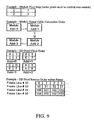
The simplified translation table example of FIG. 9 is for a display consisting of four 2×2 modules arranged in a square and connected to data output 0. The active frame size is 64 by 96 words, which translates to 64 pixels by 64 data pixels for this example. The display module switch settings are 0,0,0, the display module (Y, X) start location is (32, 1), the translation table words/line value is 82 (96 words per line−14 words header), and the data pixel/line value is set at 50.
Portions of a more complete translation table are illustrated in FIGS. 10 a-10 e. The configuration packet contains the translation table start line, end line, and number of data words; these are sent as word numbers 0x0D, 0x0E, and 0x0F, respectively. For this example, the start line value is 20 and the end line value is 24, which provides 4 lines of translation table data per frame (the last line must remain unused for error checking). The first 14 words for each translation table line contain the header information, which means 50 words remain on each line for actually transmitting the table data (200 words per frame). At 200 words per frame, it will take 21 frames for the entire translation table to be transmitted to the display module(s).
Mode of Operation
The present invention can be utilized in several modes of operation as best illustrated by FIGS. 11-13. FIGS. 11-12 illustrates an embodiment in which graphical data is stored in memory in a first array and a translation table is stored in memory and the translation table is used to map the graphical data into an arbitrary shaped second array for display on one or more display modules. The second array may be stored in memory on a preprocessing computer, or may be stored locally on a display controller or display module. The translation table itself can be constructed in several ways. In one embodiment, the translation table is designed and constructed on one or more preprocessing computers so that the desired shaped effect is obtained.
In another embodiment, a master translation table is constructed for each particular display module, and these master translation tables are assembled to form a complete translation table for the entire assembly of display modules for which are to be included in the display of this particular display data. The master translation tables could be stored in the various display modules for which they apply, or stored on a memory device which could be supplied by the manufacturer or by the output of preprocessing computer(s). Alternatively, the pixel configuration information needed to construct the master translation tables can be encoded or stored in the hardware or software of the display modules; a preprocessing computer obtains this information from the display modules to construct master translation tables or the complete translation table for the assembly of display modules.
In this way, use of a translation table allows generic graphical data can be to be translated to the graphical format required by a particular display assembly. If a different user (or a different display assembly coordinating with the display assembly being discussed), has a different display configuration (different shape, different logo or channel letters, and so forth) but it desired to display at least a portion of the same graphical data on the different display assembly, the raw or incoming graphical data does not have to be custom configured for each display assembly. Rather, the incoming graphical data (which may be stored on a memory device, which may be a “live” feed of video, textual, or other visual data being “streamed” to the various display assemblies) can be transmitted in a standard format to all display stations, and the translation tables associated with the particular display modules provide for conversion or mapping of the data as required for each display module.
In FIG. 11, a shaped second array corresponding to multiple display modules or pixel strings is illustrated, for which the arrangement of pixels within the display(s) is known but arbitrary. This is particularly advantageous when a special effect distortion is desired, or when cost-effective construction of the display requires pixels to be oriented in other than a normal rectangular grid.
In FIG. 12, channel letter type displays are illustrated, in which the same rectangular grid is used for orientation of pixels, but the display itself has arbitrary shape. This is particularly advantageous, for example, for displaying undistorted graphical data only in the channel letters, without the waste associated with transmitting all the unused graphical data which will not be displayed because it is outside the channel letters.
In another embodiment, aspects of FIGS. 11-12 can be combined, with arbitrary orientations of pixels within an arbitrary shaped display, with the present translation table invention employed to map the data as required.
FIG. 13 illustrates additional detail for the apparatus, method, and mode of operation. FIG. 13 is merely an example showing required elements plus examples of optional elements which can be grouped or selected as desired for the particular embodiment being utilized. In the example of FIG. 13, graphical data is illustrated as being transmitted to a preprocessing computer and to a video processor. A translation table is stored on a memory device as indicated, and graphical data and translation table data are transmitted between components as illustrated. Connection and data transfer to a display controller and multiple display components are also shown. The elements illustrated in FIG. 13 are not always required, and multiple similar elements may be employed for a more complicated system, but this includes the most typical elements.
Various modifications can be made to the present invention without departing from the apparent scope thereof.
Translation Table Parts List
  • 10 memory device
  • 20 translation table
  • 30 first array
  • 40 translation table
  • 50 second array
  • 60 graphical data
  • 70 graphical data transmission
  • 80 graphical data and translation table transmission
  • 90 video processor
  • 100 preprocessing computer
  • 110 display controller
  • 120 display component

Claims (8)

1. A method for displaying graphical data on a display of arbitrary shape comprising the steps of:
providing a graphical display having a non-rectangular, arbitrary shape, graphical data having an initial rectangular organizational scheme, a preprocessing computer, and a translation table;
loading the graphical data into memory on the preprocessing computer;
loading the translation table into a memory device on the preprocessing computer; and,
using the translation table to map the graphical data into a new organizational scheme configured for display on the graphical display having a non-rectangular, arbitrary shape, wherein the non-rectangular, arbitrary shape includes a channel letter display.
2. The method of claim 1, wherein the initial rectangular organizational scheme includes graphical data organized as a matrix in a rectangular array of rows and columns.
3. The method of claim 1, wherein the graphical display includes a plurality of LED modules.
4. A method, for execution by one or more processors, for displaying graphical data on a display of arbitrary shape, comprising:
providing a graphical display having an arbitrary shape;
transforming a first graphical data array corresponding to a first shape to a second graphical data array corresponding to the arbitrary shape of the graphical display; and
transmitting the transformed data to the graphical display, wherein the arbitrary shape includes a channel letter.
5. The method of claim 4, wherein transforming includes converting the first graphical data array from a rectangular graphical data array into the second graphical data array which corresponds to logical rows and logical columns of pixels, wherein the pixels define the arbitrary shape which is different than the shape of a starting rectangular image.
6. The method of claim 4, wherein transforming includes providing a map for converting rectangular rows and columns to logical rows and columns of the arbitrary shape.
7. The method of claim 4, wherein transforming includes using a translation table which is stored in a memory.
8. The method of claim 7, wherein the translation table is provided a first address corresponding to a pixel of the first graphical data array and translates the first address to a second address of the second graphical data array.
US11/805,513 2004-10-14 2007-05-23 Translation table Active 2027-08-12 US8001455B2 (en)

Priority Applications (4)

Application Number Priority Date Filing Date Title
US11/805,513 US8001455B2 (en) 2004-10-14 2007-05-23 Translation table
US13/172,102 US20120005563A1 (en) 2004-10-14 2011-06-29 Graphical data translation table
US14/027,419 US9052092B2 (en) 2004-10-14 2013-09-16 Sealed pixel assemblies, kits and methods
US14/733,346 US20150345774A1 (en) 2004-10-14 2015-06-08 Sealed pixel assemblies, kits and methods

Applications Claiming Priority (3)

Application Number Priority Date Filing Date Title
US96512704A 2004-10-14 2004-10-14
US80820006P 2006-05-24 2006-05-24
US11/805,513 US8001455B2 (en) 2004-10-14 2007-05-23 Translation table

Related Parent Applications (1)

Application Number Title Priority Date Filing Date
US96512704A Continuation-In-Part 2004-10-14 2004-10-14

Related Child Applications (1)

Application Number Title Priority Date Filing Date
US13/172,102 Continuation US20120005563A1 (en) 2004-10-14 2011-06-29 Graphical data translation table

Publications (2)

Publication Number Publication Date
US20090021532A1 US20090021532A1 (en) 2009-01-22
US8001455B2 true US8001455B2 (en) 2011-08-16

Family

ID=46331789

Family Applications (2)

Application Number Title Priority Date Filing Date
US11/805,513 Active 2027-08-12 US8001455B2 (en) 2004-10-14 2007-05-23 Translation table
US13/172,102 Abandoned US20120005563A1 (en) 2004-10-14 2011-06-29 Graphical data translation table

Family Applications After (1)

Application Number Title Priority Date Filing Date
US13/172,102 Abandoned US20120005563A1 (en) 2004-10-14 2011-06-29 Graphical data translation table

Country Status (1)

Country Link
US (2) US8001455B2 (en)

Cited By (5)

* Cited by examiner, † Cited by third party
Publication number Priority date Publication date Assignee Title
US20110102307A1 (en) * 2004-10-14 2011-05-05 Daktronics, Inc. Sealed pixel assemblies, kits and methods
US20110141139A1 (en) * 2004-10-14 2011-06-16 Daktronics, Inc. Flexible pixel hardware and method
US8344410B2 (en) 2004-10-14 2013-01-01 Daktronics, Inc. Flexible pixel element and signal distribution means
US20180090092A1 (en) * 2016-02-17 2018-03-29 Boe Technology Group Co., Ltd. Display driving method and display system
US11672067B2 (en) 2021-01-29 2023-06-06 Snap-On Incorporated Circuit board with sensor controlled lights and end-to-end connection

Families Citing this family (11)

* Cited by examiner, † Cited by third party
Publication number Priority date Publication date Assignee Title
US8001455B2 (en) 2004-10-14 2011-08-16 Daktronics, Inc. Translation table
JP5376313B2 (en) * 2009-09-03 2013-12-25 株式会社リコー Image processing apparatus and image pickup apparatus
US9416551B2 (en) 2013-12-31 2016-08-16 Ultravision Technologies, Llc Preassembled display systems and methods of installation thereof
US9195281B2 (en) 2013-12-31 2015-11-24 Ultravision Technologies, Llc System and method for a modular multi-panel display
US9582237B2 (en) * 2013-12-31 2017-02-28 Ultravision Technologies, Llc Modular display panels with different pitches
US9207904B2 (en) 2013-12-31 2015-12-08 Ultravision Technologies, Llc Multi-panel display with hot swappable display panels and methods of servicing thereof
US20150187237A1 (en) 2013-12-31 2015-07-02 Ultravision Holdings, Llc System and Method for a Modular Multi-Panel Display
US9311847B2 (en) 2014-07-16 2016-04-12 Ultravision Technologies, Llc Display system having monitoring circuit and methods thereof
KR102437567B1 (en) * 2015-10-16 2022-08-29 삼성전자주식회사 Method of application processor and display system
WO2019014229A1 (en) * 2017-07-10 2019-01-17 Ubiquiti Networks, Inc. Wearable video camera medallion with circular display
GB2567192A (en) * 2017-10-05 2019-04-10 Ga Signs Ltd Illuminated Sign

Citations (88)

* Cited by examiner, † Cited by third party
Publication number Priority date Publication date Assignee Title
US4263736A (en) 1978-10-11 1981-04-28 Colorado Time Systems, Inc. Modular display system
US4539598A (en) 1982-01-14 1985-09-03 Messerschmitt-Boelkow-Blohm Gmbh Image readout method and device
GB2164189A (en) 1984-09-05 1986-03-12 Dr Khodayar Rashidi Modular-display-system
US4751446A (en) * 1985-12-06 1988-06-14 Apollo Computer, Inc. Lookup table initialization
US4839726A (en) 1987-07-31 1989-06-13 Fairchild Weston Systems, Inc. Video enhancement method and system
US5079636A (en) 1988-07-21 1992-01-07 Magnascreen Corporation Modular flat-screen television displays and modules and circuit drives therefor
US5151689A (en) 1988-04-25 1992-09-29 Hitachi, Ltd. Display device with matrix-arranged pixels having reduced number of vertical signal lines
US5164853A (en) 1989-04-06 1992-11-17 Ricoh Company, Ltd. Liquid crystal display panel with plural substrates
US5168375A (en) 1991-09-18 1992-12-01 Polaroid Corporation Image reconstruction by use of discrete cosine and related transforms
US5261050A (en) * 1990-07-27 1993-11-09 Eastman Kodak Company Apparatus for processing a digital image for window width, level and curve shape
US5363318A (en) 1992-03-23 1994-11-08 Eastman Kodak Company Method and apparatus for adaptive color characterization and calibration
US5399390A (en) 1994-01-27 1995-03-21 Motorola, Inc. Liquid crystal display with polymeric substrate
US5440648A (en) 1991-11-19 1995-08-08 Dalsa, Inc. High speed defect detection apparatus having defect detection circuits mounted in the camera housing
US5475400A (en) 1993-11-15 1995-12-12 Media Vision Inc. Graphic card with two color look up tables
US5523769A (en) 1993-06-16 1996-06-04 Mitsubishi Electric Research Laboratories, Inc. Active modules for large screen displays
US5600574A (en) 1994-05-13 1997-02-04 Minnesota Mining And Manufacturing Company Automated image quality control
US5642125A (en) 1992-06-17 1997-06-24 Xerox Corporation Two path liquid crystal light valve color display
US5767822A (en) 1994-10-25 1998-06-16 Avix Inc. Scrolling display method and system therefor
US5796376A (en) 1991-12-18 1998-08-18 Cie Research, Inc. Electronic display sign
US5805117A (en) 1994-05-12 1998-09-08 Samsung Electronics Co., Ltd. Large area tiled modular display system
US5815168A (en) * 1995-06-23 1998-09-29 Cirrus Logic, Inc. Tiled memory addressing with programmable tile dimensions
JPH11191494A (en) 1997-12-26 1999-07-13 Abikkusu Kk Led illumination unit and led illumination system
US5946005A (en) 1995-09-21 1999-08-31 Industrial Technology Research Institute Computer graphics memory architecture having a graphics processor and a buffer
US5949581A (en) 1997-08-12 1999-09-07 Daktronics, Inc. Display system
US5949483A (en) 1994-01-28 1999-09-07 California Institute Of Technology Active pixel sensor array with multiresolution readout
US6054968A (en) 1997-11-24 2000-04-25 De Matteo; Keith Modular graphics display
US6072446A (en) 1996-05-22 2000-06-06 Avix Inc. Scroll display method and apparatus
US6169632B1 (en) 1997-08-12 2001-01-02 Daktronics, Inc. Display system
US6219099B1 (en) 1998-09-23 2001-04-17 Honeywell International Inc. Method and apparatus for calibrating a display using an array of cameras
US6259838B1 (en) 1998-10-16 2001-07-10 Sarnoff Corporation Linearly-addressed light-emitting fiber, and flat panel display employing same
US6265984B1 (en) 1999-08-09 2001-07-24 Carl Joseph Molinaroli Light emitting diode display device
US20010015709A1 (en) 2000-02-18 2001-08-23 Hitachi, Ltd. Liquid crystal display device
US6330111B1 (en) 2000-06-13 2001-12-11 Kenneth J. Myers, Edward Greenberg Lighting elements including light emitting diodes, microprism sheet, reflector, and diffusing agent
US20010049893A1 (en) 2000-01-06 2001-12-13 Maas Theodorus Mattheus Maria Luminaire and light-emitting panel
US6335728B1 (en) 1998-03-31 2002-01-01 Pioneer Corporation Display panel driving apparatus
US20020000576A1 (en) 2000-06-22 2002-01-03 Kazutaka Inukai Display device
US6362801B1 (en) 1998-06-17 2002-03-26 Engineer Lighting, Inc. Display apparatus
US20020051356A1 (en) 1998-05-11 2002-05-02 Toyoda Gosei Co., Ltd. Planar light emitting device
US6400340B1 (en) 1996-03-26 2002-06-04 Fourie Inc. Display device
US20020088984A1 (en) 2000-11-30 2002-07-11 Takatoma Toda Semiconductor chip mounting substrate, electrooptical device, liquid-crystal device, electroluminescent device, and electronic equipment
US20020122134A1 (en) 2001-03-05 2002-09-05 Kalua Kevin A. Video display array of sealed, modular units
WO2002073298A2 (en) 2001-03-14 2002-09-19 Koninklijke Philips Electronics N.V. Flexible liquid crystal display
US20030031032A1 (en) 2001-08-10 2003-02-13 Wu Chen H. Light emitting diode modules for illuminated signs
US6536914B2 (en) 2000-05-04 2003-03-25 Koninklijke Philips Electronics N.V. Illumination system, light mixing chamber and display device
US20030057886A1 (en) 1997-08-26 2003-03-27 Lys Ihor A. Methods and apparatus for controlling devices in a networked lighting system
US20030067437A1 (en) 2001-10-08 2003-04-10 Mcclintock Dale Thomas Digital playback device
US20030076281A1 (en) 1997-08-26 2003-04-24 Frederick Marshall Morgan Diffuse illumination systems and methods
US6566824B2 (en) 2001-10-16 2003-05-20 Teledyne Lighting And Display Products, Inc. Flexible lighting segment
WO2003060857A1 (en) 2002-01-21 2003-07-24 Jinming Zhang A panel display and display method thereof
US6628258B1 (en) 1998-08-03 2003-09-30 Seiko Epson Corporation Electrooptic device, substrate therefor, electronic device, and projection display
US6639574B2 (en) 2002-01-09 2003-10-28 Landmark Screens Llc Light-emitting diode display
US20040004827A1 (en) 2002-07-08 2004-01-08 Guest Christopher William Light devices using light emitting diodes
US20040041800A1 (en) 2002-09-04 2004-03-04 Daniels John James Thin, lightweight, flexible, bright, wireless display
US20040043139A1 (en) 2002-09-04 2004-03-04 Daniels John James Printer and method for manufacturing electronic circuits and displays
US6729054B1 (en) 2001-12-19 2004-05-04 Daktronics, Inc. Articulated continuous electronic display
US6736512B2 (en) 2000-02-21 2004-05-18 Sony International (Europe) Gmbh Pixel element for a three-dimensional screen
US20040207581A1 (en) 2003-04-18 2004-10-21 Miller Paul A. Modular traveling-message sign apparatus
AU2003203350A1 (en) 2003-04-01 2004-10-21 Murray, John Bernard Mr Electronic Educational Writing Aid
US20040235227A1 (en) 2002-05-17 2004-11-25 Takeo Kawase Circuit fabrication method
US20040239586A1 (en) 2003-05-30 2004-12-02 Eastman Kodak Company Flexible display
US20040253896A1 (en) 2003-02-05 2004-12-16 Semiconductor Energy Laboratory Co., Ltd. Method of manufacturing display device
US20050030321A1 (en) * 2000-04-14 2005-02-10 Picsel Research Limited Shape processor
US6856303B2 (en) 2000-10-24 2005-02-15 Daniel L. Kowalewski Rotating display system
US20050040962A1 (en) 2003-08-11 2005-02-24 Phillip Funkhouser Retractable flexible digital display apparatus
US20050046646A1 (en) 2003-09-03 2005-03-03 Mitsubishi Denki Kabushiki Kaisha Display apparatus provided with decode circuit for gray-scale expression
US6888304B2 (en) 2001-03-28 2005-05-03 Hitachi, Ltd. Display module
JP2005224983A (en) 2004-02-10 2005-08-25 Seiko Epson Corp Image output system for outputting image according to information on number of dots formed in prescribed area
US20050225976A1 (en) 2004-04-08 2005-10-13 Integrated Illumination Systems, Inc. Marine LED lighting network and driver
EP1655712A2 (en) 2004-10-14 2006-05-10 Daktronics, Inc. Flexible pixel string hardware and method cross references to related applications
US7049983B2 (en) 1999-01-28 2006-05-23 Semiconductor Energy Laboratory Co., Ltd. Serial-to-parallel conversion circuit, and semiconductor display device employing the same
US7091927B1 (en) 2003-06-26 2006-08-15 Rockwell Collins, Inc. Display including tiles and a method of operating and manufacturing the same
US20060221599A1 (en) 2005-04-01 2006-10-05 Hornsby James R Lighting and display apparatus
US7148944B2 (en) 2002-05-17 2006-12-12 Toshiba Matsushita Display Technology Co., Ltd. Bendable display apparatus and method of manufacturing the same
US20060284161A1 (en) 2005-06-15 2006-12-21 Koito Manufacturing Co., Ltd. Light source module and vehicle lamp
US7161558B1 (en) 2001-04-24 2007-01-09 Daktronics, Inc. Calibration system for an electronic sign
US7165863B1 (en) 2004-09-23 2007-01-23 Pricilla G. Thomas Illumination system
US20070148793A1 (en) 2005-12-28 2007-06-28 Semiconductor Energy Laboratory Co., Ltd. Semiconductor device, display device, and electronic device
US7295362B2 (en) 2002-08-24 2007-11-13 Maskless Lithography, Inc. Continuous direct-write optical lithography
US7417251B2 (en) 2002-07-24 2008-08-26 Nec Corporation Active matrix organic EL display device and manufacturing method thereof
US20080225143A1 (en) 2006-04-13 2008-09-18 Daktronics, Inc. Pixel interleaving configurations for use in high definition electronic sign displays
US7443028B2 (en) 2005-03-09 2008-10-28 Matsushita Electric Industrial Co., Ltd. Imaging module and method for forming the same
US20090021529A1 (en) 2004-10-14 2009-01-22 Daktronics, Inc. Flexible pixel element fabrication and sealing method
US20090021497A1 (en) 2004-10-14 2009-01-22 Daktronics, Inc. Flexible pixel element and signal distribution means
US20090021532A1 (en) 2004-10-14 2009-01-22 Gloege Chad N Translation table
US20090024867A1 (en) 2006-05-24 2009-01-22 Gloege Chad N Redundant data path
AU2005329700B2 (en) 2005-03-21 2009-01-22 He Shan Lide Electronic Enterprise Company Ltd. A flexible tubular light with flowing flicker effect
US20090024929A1 (en) 2006-05-24 2009-01-22 Gloege Chad N Remote power supply
US7893948B1 (en) 2004-10-14 2011-02-22 Daktronics, Inc. Flexible pixel hardware and method

Family Cites Families (9)

* Cited by examiner, † Cited by third party
Publication number Priority date Publication date Assignee Title
GB1595964A (en) * 1977-03-17 1981-08-19 Micro Consultants Ltd Tv Special effects generator
US5067019A (en) * 1989-03-31 1991-11-19 The United States Of America As Represented By The Administrator Of The National Aeronautics And Space Administration Programmable remapper for image processing
US5251296A (en) * 1990-03-16 1993-10-05 Hewlett-Packard Company Methods and apparatus for generating arbitrarily addressed, arbitrarily shaped tiles in computer graphics systems
WO2001057799A2 (en) * 2000-02-02 2001-08-09 Quvis, Inc. System and method for optimizing image resolution using pixelated imaging devices
WO2001095608A2 (en) * 2000-06-09 2001-12-13 Interactive Imaging Systems Inc. A method and apparatus for mapping images and video to create navigable, immersive video and images
US7475356B2 (en) * 2001-05-11 2009-01-06 Xerox Corporation System utilizing mixed resolution displays
GB0213320D0 (en) * 2002-06-11 2002-07-24 Koninkl Philips Electronics Nv Display device
US6888604B2 (en) * 2002-08-14 2005-05-03 Samsung Electronics Co., Ltd. Liquid crystal display
US8711156B1 (en) * 2004-09-30 2014-04-29 Nvidia Corporation Method and system for remapping processing elements in a pipeline of a graphics processing unit

Patent Citations (92)

* Cited by examiner, † Cited by third party
Publication number Priority date Publication date Assignee Title
US4263736A (en) 1978-10-11 1981-04-28 Colorado Time Systems, Inc. Modular display system
US4539598A (en) 1982-01-14 1985-09-03 Messerschmitt-Boelkow-Blohm Gmbh Image readout method and device
GB2164189A (en) 1984-09-05 1986-03-12 Dr Khodayar Rashidi Modular-display-system
US4751446A (en) * 1985-12-06 1988-06-14 Apollo Computer, Inc. Lookup table initialization
US4839726A (en) 1987-07-31 1989-06-13 Fairchild Weston Systems, Inc. Video enhancement method and system
US5151689A (en) 1988-04-25 1992-09-29 Hitachi, Ltd. Display device with matrix-arranged pixels having reduced number of vertical signal lines
US5079636A (en) 1988-07-21 1992-01-07 Magnascreen Corporation Modular flat-screen television displays and modules and circuit drives therefor
US5164853A (en) 1989-04-06 1992-11-17 Ricoh Company, Ltd. Liquid crystal display panel with plural substrates
US5261050A (en) * 1990-07-27 1993-11-09 Eastman Kodak Company Apparatus for processing a digital image for window width, level and curve shape
US5168375A (en) 1991-09-18 1992-12-01 Polaroid Corporation Image reconstruction by use of discrete cosine and related transforms
US5440648A (en) 1991-11-19 1995-08-08 Dalsa, Inc. High speed defect detection apparatus having defect detection circuits mounted in the camera housing
US5796376A (en) 1991-12-18 1998-08-18 Cie Research, Inc. Electronic display sign
US5363318A (en) 1992-03-23 1994-11-08 Eastman Kodak Company Method and apparatus for adaptive color characterization and calibration
US5642125A (en) 1992-06-17 1997-06-24 Xerox Corporation Two path liquid crystal light valve color display
US5523769A (en) 1993-06-16 1996-06-04 Mitsubishi Electric Research Laboratories, Inc. Active modules for large screen displays
US5475400A (en) 1993-11-15 1995-12-12 Media Vision Inc. Graphic card with two color look up tables
US5399390A (en) 1994-01-27 1995-03-21 Motorola, Inc. Liquid crystal display with polymeric substrate
US5949483A (en) 1994-01-28 1999-09-07 California Institute Of Technology Active pixel sensor array with multiresolution readout
US5805117A (en) 1994-05-12 1998-09-08 Samsung Electronics Co., Ltd. Large area tiled modular display system
US5600574A (en) 1994-05-13 1997-02-04 Minnesota Mining And Manufacturing Company Automated image quality control
US5767822A (en) 1994-10-25 1998-06-16 Avix Inc. Scrolling display method and system therefor
US5815168A (en) * 1995-06-23 1998-09-29 Cirrus Logic, Inc. Tiled memory addressing with programmable tile dimensions
US5946005A (en) 1995-09-21 1999-08-31 Industrial Technology Research Institute Computer graphics memory architecture having a graphics processor and a buffer
US6400340B1 (en) 1996-03-26 2002-06-04 Fourie Inc. Display device
US6072446A (en) 1996-05-22 2000-06-06 Avix Inc. Scroll display method and apparatus
US5949581A (en) 1997-08-12 1999-09-07 Daktronics, Inc. Display system
US6169632B1 (en) 1997-08-12 2001-01-02 Daktronics, Inc. Display system
US20030076281A1 (en) 1997-08-26 2003-04-24 Frederick Marshall Morgan Diffuse illumination systems and methods
US20030057886A1 (en) 1997-08-26 2003-03-27 Lys Ihor A. Methods and apparatus for controlling devices in a networked lighting system
US6054968A (en) 1997-11-24 2000-04-25 De Matteo; Keith Modular graphics display
JPH11191494A (en) 1997-12-26 1999-07-13 Abikkusu Kk Led illumination unit and led illumination system
US6335728B1 (en) 1998-03-31 2002-01-01 Pioneer Corporation Display panel driving apparatus
US20020051356A1 (en) 1998-05-11 2002-05-02 Toyoda Gosei Co., Ltd. Planar light emitting device
US6362801B1 (en) 1998-06-17 2002-03-26 Engineer Lighting, Inc. Display apparatus
US6628258B1 (en) 1998-08-03 2003-09-30 Seiko Epson Corporation Electrooptic device, substrate therefor, electronic device, and projection display
US6819303B1 (en) 1998-08-17 2004-11-16 Daktronics, Inc. Control system for an electronic sign (video display system)
US6219099B1 (en) 1998-09-23 2001-04-17 Honeywell International Inc. Method and apparatus for calibrating a display using an array of cameras
US6259838B1 (en) 1998-10-16 2001-07-10 Sarnoff Corporation Linearly-addressed light-emitting fiber, and flat panel display employing same
US7049983B2 (en) 1999-01-28 2006-05-23 Semiconductor Energy Laboratory Co., Ltd. Serial-to-parallel conversion circuit, and semiconductor display device employing the same
US6265984B1 (en) 1999-08-09 2001-07-24 Carl Joseph Molinaroli Light emitting diode display device
US20010049893A1 (en) 2000-01-06 2001-12-13 Maas Theodorus Mattheus Maria Luminaire and light-emitting panel
US20010015709A1 (en) 2000-02-18 2001-08-23 Hitachi, Ltd. Liquid crystal display device
US6842164B2 (en) 2000-02-18 2005-01-11 Hitachi, Ltd. Display device
US6736512B2 (en) 2000-02-21 2004-05-18 Sony International (Europe) Gmbh Pixel element for a three-dimensional screen
US20050030321A1 (en) * 2000-04-14 2005-02-10 Picsel Research Limited Shape processor
US6536914B2 (en) 2000-05-04 2003-03-25 Koninklijke Philips Electronics N.V. Illumination system, light mixing chamber and display device
US6330111B1 (en) 2000-06-13 2001-12-11 Kenneth J. Myers, Edward Greenberg Lighting elements including light emitting diodes, microprism sheet, reflector, and diffusing agent
US20020000576A1 (en) 2000-06-22 2002-01-03 Kazutaka Inukai Display device
US6856303B2 (en) 2000-10-24 2005-02-15 Daniel L. Kowalewski Rotating display system
US20020088984A1 (en) 2000-11-30 2002-07-11 Takatoma Toda Semiconductor chip mounting substrate, electrooptical device, liquid-crystal device, electroluminescent device, and electronic equipment
US6809390B2 (en) 2000-11-30 2004-10-26 Seiko Epson Corporation Semiconductor chip mounting substrate, electrooptical device, liquid-crystal device, electroluminescent device, and electronic equipment
US20020122134A1 (en) 2001-03-05 2002-09-05 Kalua Kevin A. Video display array of sealed, modular units
WO2002073298A2 (en) 2001-03-14 2002-09-19 Koninklijke Philips Electronics N.V. Flexible liquid crystal display
US6888304B2 (en) 2001-03-28 2005-05-03 Hitachi, Ltd. Display module
US7161558B1 (en) 2001-04-24 2007-01-09 Daktronics, Inc. Calibration system for an electronic sign
US20030031032A1 (en) 2001-08-10 2003-02-13 Wu Chen H. Light emitting diode modules for illuminated signs
US20030067437A1 (en) 2001-10-08 2003-04-10 Mcclintock Dale Thomas Digital playback device
US6566824B2 (en) 2001-10-16 2003-05-20 Teledyne Lighting And Display Products, Inc. Flexible lighting segment
US6729054B1 (en) 2001-12-19 2004-05-04 Daktronics, Inc. Articulated continuous electronic display
US6639574B2 (en) 2002-01-09 2003-10-28 Landmark Screens Llc Light-emitting diode display
WO2003060857A1 (en) 2002-01-21 2003-07-24 Jinming Zhang A panel display and display method thereof
US20040235227A1 (en) 2002-05-17 2004-11-25 Takeo Kawase Circuit fabrication method
US7148944B2 (en) 2002-05-17 2006-12-12 Toshiba Matsushita Display Technology Co., Ltd. Bendable display apparatus and method of manufacturing the same
US20040004827A1 (en) 2002-07-08 2004-01-08 Guest Christopher William Light devices using light emitting diodes
US7417251B2 (en) 2002-07-24 2008-08-26 Nec Corporation Active matrix organic EL display device and manufacturing method thereof
US7295362B2 (en) 2002-08-24 2007-11-13 Maskless Lithography, Inc. Continuous direct-write optical lithography
US20040041800A1 (en) 2002-09-04 2004-03-04 Daniels John James Thin, lightweight, flexible, bright, wireless display
US20040043139A1 (en) 2002-09-04 2004-03-04 Daniels John James Printer and method for manufacturing electronic circuits and displays
US20040253896A1 (en) 2003-02-05 2004-12-16 Semiconductor Energy Laboratory Co., Ltd. Method of manufacturing display device
AU2003203350A1 (en) 2003-04-01 2004-10-21 Murray, John Bernard Mr Electronic Educational Writing Aid
US20040207581A1 (en) 2003-04-18 2004-10-21 Miller Paul A. Modular traveling-message sign apparatus
US20040239586A1 (en) 2003-05-30 2004-12-02 Eastman Kodak Company Flexible display
US7091927B1 (en) 2003-06-26 2006-08-15 Rockwell Collins, Inc. Display including tiles and a method of operating and manufacturing the same
US20050040962A1 (en) 2003-08-11 2005-02-24 Phillip Funkhouser Retractable flexible digital display apparatus
US20050046646A1 (en) 2003-09-03 2005-03-03 Mitsubishi Denki Kabushiki Kaisha Display apparatus provided with decode circuit for gray-scale expression
JP2005224983A (en) 2004-02-10 2005-08-25 Seiko Epson Corp Image output system for outputting image according to information on number of dots formed in prescribed area
US20050225976A1 (en) 2004-04-08 2005-10-13 Integrated Illumination Systems, Inc. Marine LED lighting network and driver
US7165863B1 (en) 2004-09-23 2007-01-23 Pricilla G. Thomas Illumination system
EP1655712A2 (en) 2004-10-14 2006-05-10 Daktronics, Inc. Flexible pixel string hardware and method cross references to related applications
US20090021497A1 (en) 2004-10-14 2009-01-22 Daktronics, Inc. Flexible pixel element and signal distribution means
US7893948B1 (en) 2004-10-14 2011-02-22 Daktronics, Inc. Flexible pixel hardware and method
US7868903B2 (en) 2004-10-14 2011-01-11 Daktronics, Inc. Flexible pixel element fabrication and sealing method
US20090021532A1 (en) 2004-10-14 2009-01-22 Gloege Chad N Translation table
US20090021529A1 (en) 2004-10-14 2009-01-22 Daktronics, Inc. Flexible pixel element fabrication and sealing method
US7443028B2 (en) 2005-03-09 2008-10-28 Matsushita Electric Industrial Co., Ltd. Imaging module and method for forming the same
AU2005329700B2 (en) 2005-03-21 2009-01-22 He Shan Lide Electronic Enterprise Company Ltd. A flexible tubular light with flowing flicker effect
US20060221599A1 (en) 2005-04-01 2006-10-05 Hornsby James R Lighting and display apparatus
US20060284161A1 (en) 2005-06-15 2006-12-21 Koito Manufacturing Co., Ltd. Light source module and vehicle lamp
US20070148793A1 (en) 2005-12-28 2007-06-28 Semiconductor Energy Laboratory Co., Ltd. Semiconductor device, display device, and electronic device
US20080225143A1 (en) 2006-04-13 2008-09-18 Daktronics, Inc. Pixel interleaving configurations for use in high definition electronic sign displays
US20090024867A1 (en) 2006-05-24 2009-01-22 Gloege Chad N Redundant data path
US20090024929A1 (en) 2006-05-24 2009-01-22 Gloege Chad N Remote power supply

Non-Patent Citations (26)

* Cited by examiner, † Cited by third party
Title
"3-channel constant-current LED Driver with PWM control", (A6280-DS, Rev. 3), Allegro Microsystems Inc, [online]. [archived May 7, 2007]. Retrieved from the Internet: <URL:http://web.archive.org/web/20070507171052/http://www.allegromicro.com/en/Products//Part-Numbers/6280/6280>, (2007), 12 pgs.
"European Application Serial No. 08165441.0, Response filed Sep. 27, 2010", 20 pgs.
"European Application Serial No. 08795482.2, Extended European Search Report mailed Jan. 19, 2011", 12 pgs.
"International Application Serial No. PCT/US08/09936, International Preliminary Report on Patentability mailed Aug. 24, 2010", 6 pgs.
"International Application Serial No. PCT/US08/09936, International Search Report mailed Nov. 10, 2008", 1 pg.
"International Application Serial No. PCT/US08/09936, Written Opinion mailed Nov. 10, 2008", 3 pgs.
"International Application Serial No. PCT/US08/09941, International Search Report mailed Nov. 17, 2008", 1 pg.
"International Application Serial No. PCT/US08/09941, Written Opinion mailed Nov. 17, 2008", 6 pgs.
"U.S. Appl. No. 10/965,133, Final Office Action mailed Nov. 17, 2009", 9 pgs.
"U.S. Appl. No. 10/965,133, Non Final Office Action mailed Jul. 10, 2006", 5 pgs.
"U.S. Appl. No. 10/965,133, Non Final Office Action mailed Jun. 2, 2008", 5 pgs.
"U.S. Appl. No. 10/965,133, Non Final Office Action mailed Oct. 26, 2007", 6 pgs.
"U.S. Appl. No. 10/965,133, Non-Final Office Action mailed May 25, 2010", 10 pgs.
"U.S. Appl. No. 10/965,133, Notice of Allowance mailed Oct. 18, 2010", 7 pgs.
"U.S. Appl. No. 10/965,133, Response filed Aug. 25, 2010 to Non Final Office Action mailed May 25, 2010", 8 pgs.
"U.S. Appl. No. 10/965,133, Response filed Feb. 14, 2008 to Non Final Office Action mailed Oct. 26, 2007", 16 pgs.
"U.S. Appl. No. 10/965,133, Response filed Jan. 10, 2007 to Non Final Office Action mailed Jul. 10, 2006", 9 pgs.
"U.S. Appl. No. 10/965,133, Response filed Jun. 2, 2009 to Non Final Office Action mailed Jun. 2, 2008", 13 pgs.
"U.S. Appl. No. 10/965,133, Response filed May 17, 2010 to Final Office Action mailed Nov. 17, 2009", 11 pgs.
"U.S. Appl. No. 11/895,424, Non-Final Office Action mailed Mar. 12, 2010", 6 pgs.
"U.S. Appl. No. 11/895,424, Notice of Allowance mailed Sep. 10, 2010", 13 pgs.
"U.S. Appl. No. 11/895,424, Response filed Jun. 11, 2010 to Non-Final Office Action mailed Mar. 12, 2010", 8 pgs.
Baumann, "Management of Multidimensional Discrete Data" VLDB Journal, May 3, 1994, p. 401-444. *
Matkovic, "Tone Mapping Techniques and Color Image Difference in Global Illumination", Dissertation, Feb. 1998, p. 1-118. *
Schwesig, C., et al., "Gummi: a bendable computer", Proceedings of the SIGCHI Conference on Human Factors in Computing Systems CHI '04, (Apr. 2004), 263-270.
Van Baar, J., et al., "Seamless multi-projector display on curved screens", Proceedings of the workshop on Virtual environments 2003 EGVE '03, (May 2003), 281-286.

Cited By (12)

* Cited by examiner, † Cited by third party
Publication number Priority date Publication date Assignee Title
US20110102307A1 (en) * 2004-10-14 2011-05-05 Daktronics, Inc. Sealed pixel assemblies, kits and methods
US20110141139A1 (en) * 2004-10-14 2011-06-16 Daktronics, Inc. Flexible pixel hardware and method
US8106923B2 (en) 2004-10-14 2012-01-31 Daktronics, Inc. Flexible pixel hardware and method
US8344410B2 (en) 2004-10-14 2013-01-01 Daktronics, Inc. Flexible pixel element and signal distribution means
US8363038B2 (en) 2004-10-14 2013-01-29 Daktronics, Inc. Flexible pixel hardware and method
US8552928B2 (en) 2004-10-14 2013-10-08 Daktronics, Inc. Sealed pixel assemblies, kits and methods
US8552929B2 (en) 2004-10-14 2013-10-08 Daktronics, Inc. Flexible pixel hardware and method
US8604509B2 (en) 2004-10-14 2013-12-10 Daktronics, Inc. Flexible pixel element and signal distribution means
US9052092B2 (en) 2004-10-14 2015-06-09 Daktronics, Inc. Sealed pixel assemblies, kits and methods
US20180090092A1 (en) * 2016-02-17 2018-03-29 Boe Technology Group Co., Ltd. Display driving method and display system
US10304405B2 (en) * 2016-02-17 2019-05-28 Boe Technology Group Co., Ltd. Display driving method for driving display system and display system
US11672067B2 (en) 2021-01-29 2023-06-06 Snap-On Incorporated Circuit board with sensor controlled lights and end-to-end connection

Also Published As

Publication number Publication date
US20090021532A1 (en) 2009-01-22
US20120005563A1 (en) 2012-01-05

Similar Documents

Publication Publication Date Title
US8001455B2 (en) Translation table
CN100576294C (en) Abnormity generation method of display data and special-shaped display system
US7646357B2 (en) Control system for an electronic sign (video display system)
US7928968B2 (en) Apparatus for displaying advertisement image
JP5704119B2 (en) Light emitting device, communication method, display unit
US5796376A (en) Electronic display sign
US20040008155A1 (en) Electronic system for tiled displays
JPH11126044A (en) Display system
CA2226479C (en) Scrolling display method and apparatus
CN107567710B (en) System and method for processing video data
EP0378653B1 (en) Apparatus for generating video signals
US20030222893A1 (en) Light emitting diode display and method for the illumination thereof
JP4755799B2 (en) Continuous LED display system
EP2169617B1 (en) Translation table
JP2005182055A5 (en)
KR100958611B1 (en) Display system
CN201204025Y (en) Special-shaped display system
CN114637711A (en) Chip control method, control data transmission method and device and computer equipment
KR20000074497A (en) Led display system for electric lightening board
CN114783366B (en) Display method and device based on special-shaped module and LED display screen
JP2002244633A (en) Large-sized video display device
KR101468995B1 (en) Method for displaying image in linear-disposed plurality of lighting diodes of scene lighting display system and cene lighting display system
JP6080456B2 (en) Video display device
CN212084639U (en) Control system for tone mapping of LED display screen
KR100318277B1 (en) Apparatus For Controlling Color Level of Image Display System with Light Emitting Diode Array and method for controlling the same

Legal Events

Date Code Title Description
AS Assignment

Owner name: DAKTRONICS, INC., SOUTH DAKOTA

Free format text: ASSIGNMENT OF ASSIGNORS INTEREST;ASSIGNORS:GLOEGE, CHAD N.;MUELLER, MATTHEW R.;BURGHARDT, NEIL R.;AND OTHERS;REEL/FRAME:019751/0637

Effective date: 20070618

FEPP Fee payment procedure

Free format text: PAYOR NUMBER ASSIGNED (ORIGINAL EVENT CODE: ASPN); ENTITY STATUS OF PATENT OWNER: LARGE ENTITY

STCF Information on status: patent grant

Free format text: PATENTED CASE

FPAY Fee payment

Year of fee payment: 4

MAFP Maintenance fee payment

Free format text: PAYMENT OF MAINTENANCE FEE, 8TH YEAR, LARGE ENTITY (ORIGINAL EVENT CODE: M1552); ENTITY STATUS OF PATENT OWNER: LARGE ENTITY

Year of fee payment: 8

MAFP Maintenance fee payment

Free format text: PAYMENT OF MAINTENANCE FEE, 12TH YEAR, LARGE ENTITY (ORIGINAL EVENT CODE: M1553); ENTITY STATUS OF PATENT OWNER: LARGE ENTITY

Year of fee payment: 12

AS Assignment

Owner name: JPMORGAN CHASE BANK, N.A., AS ADMINISTRATIVE AGENT, ILLINOIS

Free format text: SECURITY INTEREST;ASSIGNOR:DAKTRONICS, INC.;REEL/FRAME:063622/0039

Effective date: 20230511