US7967404B2 - Display unit installing structure for refrigerator - Google Patents
Display unit installing structure for refrigerator Download PDFInfo
- Publication number
- US7967404B2 US7967404B2 US11/722,795 US72279505A US7967404B2 US 7967404 B2 US7967404 B2 US 7967404B2 US 72279505 A US72279505 A US 72279505A US 7967404 B2 US7967404 B2 US 7967404B2
- Authority
- US
- United States
- Prior art keywords
- display unit
- unit
- accommodating
- accommodating unit
- refrigerator
- Prior art date
- Legal status (The legal status is an assumption and is not a legal conclusion. Google has not performed a legal analysis and makes no representation as to the accuracy of the status listed.)
- Expired - Fee Related, expires
Links
Images


Classifications
-
- F—MECHANICAL ENGINEERING; LIGHTING; HEATING; WEAPONS; BLASTING
- F16—ENGINEERING ELEMENTS AND UNITS; GENERAL MEASURES FOR PRODUCING AND MAINTAINING EFFECTIVE FUNCTIONING OF MACHINES OR INSTALLATIONS; THERMAL INSULATION IN GENERAL
- F16M—FRAMES, CASINGS OR BEDS OF ENGINES, MACHINES OR APPARATUS, NOT SPECIFIC TO ENGINES, MACHINES OR APPARATUS PROVIDED FOR ELSEWHERE; STANDS; SUPPORTS
- F16M11/00—Stands or trestles as supports for apparatus or articles placed thereon Stands for scientific apparatus such as gravitational force meters
- F16M11/02—Heads
- F16M11/04—Means for attachment of apparatus; Means allowing adjustment of the apparatus relatively to the stand
-
- F—MECHANICAL ENGINEERING; LIGHTING; HEATING; WEAPONS; BLASTING
- F16—ENGINEERING ELEMENTS AND UNITS; GENERAL MEASURES FOR PRODUCING AND MAINTAINING EFFECTIVE FUNCTIONING OF MACHINES OR INSTALLATIONS; THERMAL INSULATION IN GENERAL
- F16M—FRAMES, CASINGS OR BEDS OF ENGINES, MACHINES OR APPARATUS, NOT SPECIFIC TO ENGINES, MACHINES OR APPARATUS PROVIDED FOR ELSEWHERE; STANDS; SUPPORTS
- F16M11/00—Stands or trestles as supports for apparatus or articles placed thereon Stands for scientific apparatus such as gravitational force meters
- F16M11/20—Undercarriages with or without wheels
- F16M11/2092—Undercarriages with or without wheels comprising means allowing depth adjustment, i.e. forward-backward translation of the head relatively to the undercarriage
-
- F—MECHANICAL ENGINEERING; LIGHTING; HEATING; WEAPONS; BLASTING
- F16—ENGINEERING ELEMENTS AND UNITS; GENERAL MEASURES FOR PRODUCING AND MAINTAINING EFFECTIVE FUNCTIONING OF MACHINES OR INSTALLATIONS; THERMAL INSULATION IN GENERAL
- F16M—FRAMES, CASINGS OR BEDS OF ENGINES, MACHINES OR APPARATUS, NOT SPECIFIC TO ENGINES, MACHINES OR APPARATUS PROVIDED FOR ELSEWHERE; STANDS; SUPPORTS
- F16M13/00—Other supports for positioning apparatus or articles; Means for steadying hand-held apparatus or articles
- F16M13/02—Other supports for positioning apparatus or articles; Means for steadying hand-held apparatus or articles for supporting on, or attaching to, an object, e.g. tree, gate, window-frame, cycle
-
- F—MECHANICAL ENGINEERING; LIGHTING; HEATING; WEAPONS; BLASTING
- F25—REFRIGERATION OR COOLING; COMBINED HEATING AND REFRIGERATION SYSTEMS; HEAT PUMP SYSTEMS; MANUFACTURE OR STORAGE OF ICE; LIQUEFACTION SOLIDIFICATION OF GASES
- F25D—REFRIGERATORS; COLD ROOMS; ICE-BOXES; COOLING OR FREEZING APPARATUS NOT OTHERWISE PROVIDED FOR
- F25D29/00—Arrangement or mounting of control or safety devices
- F25D29/005—Mounting of control devices
-
- F—MECHANICAL ENGINEERING; LIGHTING; HEATING; WEAPONS; BLASTING
- F16—ENGINEERING ELEMENTS AND UNITS; GENERAL MEASURES FOR PRODUCING AND MAINTAINING EFFECTIVE FUNCTIONING OF MACHINES OR INSTALLATIONS; THERMAL INSULATION IN GENERAL
- F16M—FRAMES, CASINGS OR BEDS OF ENGINES, MACHINES OR APPARATUS, NOT SPECIFIC TO ENGINES, MACHINES OR APPARATUS PROVIDED FOR ELSEWHERE; STANDS; SUPPORTS
- F16M2200/00—Details of stands or supports
- F16M2200/04—Balancing means
- F16M2200/041—Balancing means for balancing rotational movement of the head
-
- F—MECHANICAL ENGINEERING; LIGHTING; HEATING; WEAPONS; BLASTING
- F16—ENGINEERING ELEMENTS AND UNITS; GENERAL MEASURES FOR PRODUCING AND MAINTAINING EFFECTIVE FUNCTIONING OF MACHINES OR INSTALLATIONS; THERMAL INSULATION IN GENERAL
- F16M—FRAMES, CASINGS OR BEDS OF ENGINES, MACHINES OR APPARATUS, NOT SPECIFIC TO ENGINES, MACHINES OR APPARATUS PROVIDED FOR ELSEWHERE; STANDS; SUPPORTS
- F16M2200/00—Details of stands or supports
- F16M2200/06—Arms
- F16M2200/063—Parallelogram arms
-
- F—MECHANICAL ENGINEERING; LIGHTING; HEATING; WEAPONS; BLASTING
- F25—REFRIGERATION OR COOLING; COMBINED HEATING AND REFRIGERATION SYSTEMS; HEAT PUMP SYSTEMS; MANUFACTURE OR STORAGE OF ICE; LIQUEFACTION SOLIDIFICATION OF GASES
- F25D—REFRIGERATORS; COLD ROOMS; ICE-BOXES; COOLING OR FREEZING APPARATUS NOT OTHERWISE PROVIDED FOR
- F25D2400/00—General features of, or devices for refrigerators, cold rooms, ice-boxes, or for cooling or freezing apparatus not covered by any other subclass
- F25D2400/18—Aesthetic features
-
- F—MECHANICAL ENGINEERING; LIGHTING; HEATING; WEAPONS; BLASTING
- F25—REFRIGERATION OR COOLING; COMBINED HEATING AND REFRIGERATION SYSTEMS; HEAT PUMP SYSTEMS; MANUFACTURE OR STORAGE OF ICE; LIQUEFACTION SOLIDIFICATION OF GASES
- F25D—REFRIGERATORS; COLD ROOMS; ICE-BOXES; COOLING OR FREEZING APPARATUS NOT OTHERWISE PROVIDED FOR
- F25D2400/00—General features of, or devices for refrigerators, cold rooms, ice-boxes, or for cooling or freezing apparatus not covered by any other subclass
- F25D2400/36—Visual displays
- F25D2400/361—Interactive visual displays
Definitions
- the present invention relates to a refrigerator, and more particularly, to a display unit installing structure for a refrigerator which can be used to retractably mount a display unit to a portion on a refrigerator door.
- Refrigerators are household appliances for storing foods in a refrigerating or freezing chamber thereof in a refrigerated or frozen state.
- recently available refrigerators are provided with additional devices such as a dispenser and home bar to allow a user to withdraw water or foods stored in the refrigerator without opening the door, so that their convenience of user can be increased.
- refrigerators may be provided with a display unit on which a variety of information can be displayed and operating signals can be inputted.
- FIG. 1 shows a refrigerator mounted with a display unit according to a prior art.
- a main body 1 of a refrigerator is provided with a storage space divided into a refrigerating chamber and a freezing chamber.
- the refrigerator shown in FIG. 1 is a side-by-side refrigerator in which the freezing and refrigerating chambers are formed from side to side.
- Such freezing and refrigerating chambers are selectively opened and closed by a freezing chamber door 2 a and a refrigerating chamber door 2 b , respectively.
- a dispenser 4 is installed at a portion of the freezing chamber door 2 a .
- the dispenser 4 allows a user to take water out from the refrigerator without opening the freezing or refrigerating chamber door 2 a or 2 b.
- a display unit 6 is mounted to the refrigerating chamber door 2 b .
- the display unit 6 is used to display information about the refrigerator operation, to output images and sounds or to connect to the Internet.
- the display unit 6 receives a variety of operating signals required for performing the aforementioned operations.
- the display unit 6 is fixed to a refrigerator in a state where it is installed in an accommodating unit provided on a front surface of the refrigerating chamber door 2 b.
- the conventional display unit installing structure for a refrigerator so configured has the following problems.
- the display unit 6 is mounted on the front surface of the refrigerating chamber door 2 b . That is, the display unit is mounted such that a user can have the best field of vision as viewed from the front. Nevertheless, since the display unit is fixed to the front surface of the refrigerating chamber door 2 b , there is a disadvantage in that an inferior filed of vision may be obtained depending on positions of the user.
- the display unit is fixed to the front surface of the refrigerating chamber door 2 b , the external appearance of the refrigerating chamber door 2 b cannot be further changed in a state where the display unit 6 is fixed. Therefore, since there is no possibility of the change in design of the external appearance of the refrigerator, the external appearance of the front surface of the refrigerator becomes monotonous.
- the display unit 6 is generally configured in such a manner that it front surface, i.e. a portion thereof in which a liquid crystal is provided, is always directed to the front surface of the door 2 b . Therefore, since the front surface of the display unit 6 is exposed to the outside even when the display unit 6 is not being used for the purpose of transport or storage of the refrigerator, the display unit may be damaged due to external shock or contaminated with foreign substances.
- an object of the present invention is to provide a display unit installing structure for a refrigerator configured to obtain a better field of vision regardless of positions of a user.
- Another object of the present invention is to provide a display unit installing structure for a refrigerator configured such that heat transfer between a display unit and the interior of the refrigerator can be blocked as well as efficient heat radiation from the display unit can be made.
- a further object of the present invention is to provide a display unit installing structure for a refrigerator configured such that the design of an external appearance of a refrigerator door can be changed in various ways.
- a still further object of the present invention is to provide a display unit installing structure for a refrigerator configured such that a display unit can be safely protected from external shock when the display unit is not used.
- a still further object of the present invention is to provide a display unit installing structure for a refrigerator configured to be capable of making a short note thereon.
- a still further object of the present invention is to provide a display unit installing structure for a refrigerator configured such that a display unit received in a door can be maintained at a more stable state.
- a display unit installing structure for a refrigerator comprising an accommodating unit which is formed by depressing a portion on a front surface of a door and in which a display unit for displaying a variety of information thereon and inputting operating signals are retractably installed, a link mechanism for guiding accommodation and withdrawal of the display unit and tiltably supporting the display unit withdrawn from the accommodating unit at a predetermined angle, and a locking means for preventing the display unit from being inadvertently escaping from the accommodating unit.
- the locking means may include at least one locking protrusion provided on one of the accommodating unit and the display unit, and at least one locking groove provided on the other of the accommodating unit and display unit such that the locking protrusion is selectively inserted in the locking groove as the display unit is received in or withdrawn from the accommodating unit.
- the locking protrusion is shaped as a taper of which diameter is decreased from a base toward a tip end thereof, and the locking groove is shaped as a taper corresponding to the shape of the locking protrusion.
- the locking protrusion and groove are protruded from a bottom surface of the accommodating unit and depressed into a rear surface of the display unit, respectively, in accordance with a trajectory along which the display unit is received into or withdrawn from the accommodating unit by means of the link mechanism.
- the locking means may include a magnet provided at one of the accommodating unit and the display unit to come into close contact with the other of the accommodating unit and the display unit, which are made of metal, due to a magnetic force when the display unit is received in the accommodating unit.
- the display unit installing structure may further comprise a guide means for guiding the display unit to be received in the accommodating unit.
- the guide means may include at least one pair of guide ribs which are provided on opposite side surfaces of the accommodating unit and brought into close contact with side surfaces of the display unit received in the accommodating unit to support the display unit thereon.
- the guide rib is formed by protruding a portion of the side surface of the accommodating unit in an opposite direction and a guide surface inclined to be flared outwardly is provided at an outer end of the guide rib to guide the accommodation and withdrawal of the display unit.
- the link mechanism may include at least one link member of which both ends are pivotally connected to a bottom surface of the accommodating unit and a rear surface of the display unit, respectively.
- the link member may include first and second link members arranged in parallel with each other in a vertical or horizontal direction.
- each of the first and second link members is a multi-point linkage.
- both ends of the link member are pivotally connected to a front surface of a bracket detachably installed at the bottom surface of the accommodating unit and a rear surface of a mounting plate fixed to the rear surface of the display unit, respectively.
- At least one pair of fastening slots are formed on the bottom surface of the accommodating unit to be parallel with and spaced apart from each other by a predetermined distance, and fastening and locking pieces are formed on the rear surface of the bracket to be inserted in the fastening slots, respectively.
- the fastening piece is formed such that it extends perpendicular to the rear surface of the bracket corresponding to one pair of the fastening slots and a tip portion thereof is then bent to be inclined upward at a predetermined angle, and the locking piece is formed such that it extends perpendicular to the rear surface of the bracket corresponding to the other pair of the fastening slots.
- At least one positioning protrusion is provided on one of the bottom surface of the accommodating unit or the rear surface of the bracket, and at least one positioning hole is formed in the other of the bottom surface of the accommodating unit or the rear surface of the bracket such that the positioning protrusion can be fitted into the positioning hole only when the bracket is correctly positioned while the bracket is installed on the bottom surface of the accommodating unit.
- the display unit installing structure may further comprise a coil spring of which both ends are fixed to the bottom surface of the accommodating unit and the rear surface of the display unit, respectively, and which is maximally stretched at a middle point between a state where the display unit is received and a state where the display unit is fully withdrawn.
- the display unit installing structure may further comprise a coil spring of which both ends are fixed to one end of the first link member corresponding to one of the bottom surface of the accommodating unit and the rear surface of the display unit and to one end of the second link member corresponding to the other of the bottom surface of the accommodating unit and the rear surface of the display unit, respectively, and which is maximally stretched at a middle point between a state where the display unit is received and a state where the display unit is fully withdrawn.
- the accommodating unit is defined by a recess member provided on the front surface of the door.
- the display unit installing structure may further comprise a connector capable of tiltably connecting the display unit with respect to the link mechanism.
- a handle gripped when a user withdraws the display unit from the accommodating unit is provided on a bottom surface of the display unit.
- a display unit installing structure for a refrigerator comprising an accommodating unit which is formed by depressing a portion on a front surface of a door and in which a display unit for displaying a variety of information thereon and inputting operating signals are retractably installed; a link mechanism for guiding accommodation and withdrawal of the display unit and pivotally supporting the display unit withdrawn from the accommodating unit in a horizontal direction, the link mechanism including at least one pair of first link members of which one end is pivotally connected to the accommodating unit and at least one pair of second link members of which both ends are pivotally connected to a point on a top or bottom surface of the display unit and the other end of the first link member, respectively; and a locking means provided on one side of the accommodating unit and one corresponding side of the display unit to prevent the display unit from being inadvertently escaping from the accommodating unit.
- a display unit installing structure for a refrigerator comprising an accommodating unit which is formed by depressing a portion on a front surface of a door and in which a display unit for displaying a variety of information thereon and inputting operating signals are retractably installed; a link mechanism for guiding accommodation and withdrawal of the display unit and pivotally supporting the display unit withdrawn from the accommodating unit in a horizontal direction, the link mechanism including at least one pair of link members of which one end is pivotally connected to the accommodating unit while being movable in a horizontal direction and the other end is pivotally connected to a point on a top or bottom surface of the display unit; and a locking means provided on one side of the accommodating unit and one corresponding side of the display unit to prevent the display unit from being inadvertently escaping from the accommodating unit.
- a rear surface of the display unit is made of the same material as the front surface of the door.
- a white board capable of making a note or erasing the note is provided on a rear surface of the display unit.
- a memo board is provided on a rear surface of the display unit and comprises a base plate formed on the rear surface of the display unit to correspond to the surface shape of the display unit, a film with a rear surface thereof brought into close contact with a front surface of the base plate to allow a user to make a note thereon, and an eraser lever for erasing the note by separating the film from the base plate.
- the locking means may comprise a stopper movably installed on one of side surfaces of the accommodating unit and display unit in a direction perpendicular to a direction in which the display unit is received in the accommodating unit, a stopping groove formed on the other of the side surfaces of the accommodating unit and display unit to allow the stopper to be selectively inserted therein, and an elastic member for imparting an elastic force to the stopper in a direction in which the stopper is inserted in the stopping groove.
- a tip end of the stopper is shaped as a spherical surface such that the stopper does not hinder the display unit from being received in the accommodating unit.
- the locking means may comprise an operating lever installed to penetrate the front surface of the door such that a portion of the lever protrudes forward from the door to be movable in a vertical or horizontal direction; a catching protrusion provided on one end of the operating lever such that at least a portion of the catching protrusion is positioned within the accommodating unit; a catching groove formed at a side surface of the display unit such that the catching protrusion can be selectively inserted in the catching groove by moving the operating lever in a state where the display unit is received in the accommodating unit; and an elastic member for imparting an elastic force to the catching protrusion in a direction in which the catching protrusion is inserted in the catching groove.
- an inclined guide surface is provided on a tip end of the catching protrusion such that the catching protrusion does not hinder the display unit from being received in the accommodating unit.
- a seating groove is formed on a top and/or bottom surface of the display unit by depressing a portion of a rear end on the top and/or bottom surface in an upward or downward direction, the seating groove is pivotally connected to an end of the link member, and the link mechanism is seated in the seating groove in a state where the display unit is received in the accommodating unit.
- the display unit can be retractably mounted to the front surface of the refrigerator door. Therefore, there are some advantages in that a better field of vision can be substantially obtained enough for a user to view the display unit regardless of positions of the user, the heat transfer between the display unit and the interior of the refrigerator can be blocked, heat radiation efficiency of the display unit can also be improved, the design of the refrigerator door can be provided in various ways, and the display unit can be kept at a more stable state.
- FIG. 1 is a perspective view showing an external appearance of a refrigerator mounted with a display unit according to a prior art.
- FIG. 2 is a side sectional view showing a state where a display unit is withdrawn by using a display unit installing structure for a refrigerator according to a first embodiment of the present invention.
- FIG. 3 is a side sectional view showing a state where the display unit is accommodated according to the first embodiment shown in FIG. 2 .
- FIG. 4 is a front view showing a state where the display unit is accommodated according to the first embodiment shown in FIG. 2 .
- FIG. 5 is a side sectional view showing a state where a display unit is withdrawn by using a display unit installing structure for a refrigerator according to a second embodiment of the present invention.
- FIG. 6 is an exploded perspective view showing the configuration of a rear surface of an accommodating unit and a bracket constituting the second embodiment shown in FIG. 5 .
- FIG. 7 is a side sectional view showing a process of accommodating and/or withdrawing a display unit according to the second embodiment shown in FIG. 5 .
- FIG. 8 is a side sectional view showing a third embodiment of a display unit installing structure for a refrigerator according to the present invention.
- FIG. 9 is a side sectional view showing a fourth embodiment of a display unit installing structure for a refrigerator according to the present invention.
- FIGS. 10 and 11 are plan views showing an operating state of the display unit installing structure according to the embodiment shown in FIG. 9 .
- FIG. 12 is a perspective view showing major components of a refrigerator to which a display unit is mounted by using a display unit installing structure for a refrigerator according to a fifth embodiment of the present invention.
- FIG. 13 is a plan view of the embodiment shown in FIG. 12 .
- FIG. 14 is a perspective view showing a process of operating a display unit mounted by using the display unit installing structure according to the embodiment shown in FIG. 12 .
- FIG. 15 is a perspective view showing a sixth embodiment of a display unit installing structure for a refrigerator according to the present invention.
- FIG. 16 is a perspective view showing a seventh embodiment of a display unit installing structure for a refrigerator according to the present invention.
- FIG. 17 is a plan view showing an eighth embodiment of a display unit installing structure for a refrigerator according to the present invention.
- FIG. 18 is a plan view showing a ninth embodiment of a display unit installing structure for a refrigerator according to the present invention.
- FIG. 19 is a plan view showing a tenth embodiment of a display unit installing structure for a refrigerator according to the present invention.
- FIG. 20 is a plan view showing an eleventh embodiment of a display unit installing structure for a refrigerator according to the present invention.
- FIG. 21 is a side sectional view showing the embodiment shown in FIG. 20 .
- FIG. 2 shows a state where a display unit is withdrawn by using a display unit installing structure for a refrigerator according to a first embodiment of the present invention
- FIGS. 3 and 4 show a state where the display unit is accommodated according to the embodiment shown in FIG. 2 .
- an accommodating unit 12 is provided in a front surface of a refrigerator door 10 .
- the accommodating unit 12 is formed into a flat box with an open front face.
- the accommodating unit 12 is defined by a recess member 20 installed on a front surface of the door 10 . That is, the recess member 20 is installed on the front surface of the door 10 , and thus, the accommodating unit 12 can be defined by a concave portion of the recess member 20 .
- the accommodating unit 12 can be formed integrally with the front surface of the door 10 .
- a display unit 30 is retractably installed in the accommodating unit 12 .
- the accommodating unit 12 and the display unit 30 be formed to correspond to each other in view of their shapes.
- the display unit 30 displays a variety of information to the outside and receives operating signals for performing the information display.
- the display unit 30 is provided with a function of receiving a television broadcast or connecting to the Internet.
- a link mechanism 40 is provided to guide a withdrawing/accommodating motion of the display unit 30 .
- the link mechanism 40 comprises a pair of link members 42 and 44 which are arranged vertically in parallel with each other.
- both ends of the link members 42 and 44 are pivotally connected to a bottom surface of the recess member 20 and a rear surface of the display unit 30 , respectively, the link members 42 and 44 can be pivoted on rear ends thereof, respectively, in a vertical direction.
- the display unit 30 is moved horizontally due to its vertical pivot motion such that it can be received in and withdrawn from the accommodating unit 12 . That is, the display unit 30 is pivoted on supporting points corresponding to the rear ends of the link members 42 and 44 and consequently performs a motion along an arc with a predetermined radius.
- the link members 42 and 44 can be configured to be withdrawn from the accommodating unit 12 while the display unit 30 is pivoted in a horizontal direction.
- the link mechanism 40 comprises a pair of link members 42 and 44 each of which is a one-point linkage.
- the display unit 30 is withdrawn to the outside to the outside of the accommodating unit 12 while it is being kept at a vertical state.
- the link mechanism 40 is constructed into a single one-point linkage or configured to include the link members each of which is a multi-point linkage, e.g. a two-point linkage, a tilting angle of the display unit 30 can also be adjusted.
- a plurality of locking protrusions 14 are provided on the bottom surface of the accommodating unit 12 .
- Each of the locking protrusions 14 protrudes forward from the bottom surface of the accommodating unit 12 by a predetermined length.
- a plurality of locking grooves 31 in which the plurality of locking protrusions 14 are fitted are also formed in the rear surface of the display unit 30 .
- Each of the locking grooves 31 is depressed inward in the rear surface of the display unit 30 by a depth equal to the length of the locking protrusion 14 .
- the locking protrusions and grooves 14 and 31 function to prevent the display unit 30 from being inadvertently withdrawn from the accommodating unit due to the impact, which may be generated during the opening/closing operation of the door 10 , when the display unit 30 is received in the accommodating unit 12 .
- the locking protrusions 14 can be selectively inserted in the locking grooves 31 when the display unit 30 is received in or withdrawn from the accommodating unit 12 .
- each of the locking protrusions 14 takes the shape of a taper of which diameter is relatively decreased from the base to the tip end.
- Each of the locking grooves 31 is formed to have a shape corresponding to the shape of the locking protrusion 14 .
- the four locking protrusions 14 are provided at the corners on the bottom surface of the accommodating unit 12 , respectively. Accordingly, the four locking grooves 31 are also provided at the corresponding corners on the rear surface of the display unit 30 , respectively.
- the shapes and positions of the locking protrusions and grooves 14 and 31 are not limited thereto. That is, the locking protrusions and grooves 14 and 31 may be formed in any shapes and at any positions if they can prevent the display unit 30 from being inadvertently withdrawn from the accommodating unit 12 through their mutual coupling.
- the locking protrusions and grooves 14 and 31 are protruded and depressed in a horizontal direction, both of them may be protruded and depressed in a direction corresponding to a trajectory along which the display unit 30 is received in or withdrawn from the accommodating unit 12 . That is, the tip end of the locking protrusion 14 may be formed to be upward inclined in harmony with the trajectory of the display unit 30 which is moved along an arc by means of the link mechanism 40 . Accordingly, the opening of the locking groove 31 will be formed to be downward inclined in correspondence with the locking protrusion 14 .
- a plurality of guide ribs 16 are provided on opposite side surfaces, i.e. upper, lower and lateral side surfaces of the accommodating unit 12 .
- the guide ribs 16 serve to guide and support the display unit 30 to be received in the accommodating unit 12 .
- the guide ribs 16 are provided to extend from the bottom surface to the opened front of the accommodating unit 12 . Further, the guide ribs 16 protrude from the side surfaces of the accommodating unit 12 in a direction in which they face each other. Therefore, when the display unit 30 is received in the accommodating unit 12 , the guide ribs 16 are brought into close contact with the side surfaces of the display unit 30 such that they can support the display unit 30 .
- the guide ribs 16 have the same protruding heights as one another, as shown in FIG. 4 . That is, since gaps between the side surfaces of the accommodating unit 12 and the side surfaces of the display unit 30 received therein can be equal to each other, the display unit 30 can be received in an exact position.
- the guide ribs 16 are brought into close contact with the side surfaces of the display unit 30 . Accordingly, the display unit cannot be inadvertently withdrawn from the accommodating unit 12 , even though an external shock is exerted on the display unit 30 received in the accommodating unit 12 .
- a guide surface 16 a is provided on an outer end of the guide rib 16 .
- the guide surface 16 a is inclined to be flared outwardly.
- the guide surface 16 a functions to guide the display unit 30 to a proper position in the accommodating unit 12 .
- a pair of guide ribs 16 are provided at each of the side surfaces, i.e. the upper, lower and two lateral surfaces of the accommodating unit 12 .
- the number and positions of the guide ribs 16 may be determined in consideration of the sizes of the display unit 30 and the accommodating unit 12 .
- FIG. 5 shows a state where a display unit is withdrawn by using the display unit installing structure for a refrigerator according to the second embodiment of the present invention
- FIG. 6 shows a recess member and a bracket constituting the second embodiment shown in FIG. 5
- FIG. 7 shows a process of accommodating and/or withdrawing the display unit according to the second embodiment shown in FIG. 5 .
- a display unit 30 is retractably installed in an accommodating unit 12 provided on a front surface of a refrigerator door 10 .
- the accommodating unit 12 is defined by a recess member 20 provided on the front surface of the door 10 .
- a link mechanism 40 is provided to guide the accommodation and withdrawal of the display unit 30 .
- the link mechanism 40 is composed of first and second link members 42 and 44 .
- Rear ends of the link members 42 and 44 are pivotally connected to a front surface of a bracket 50 provided on a bottom surface of the recess member 20 corresponding to a bottom surface of the accommodating unit 12 .
- front ends of the link members 42 and 44 are pivotally connected to a rear surface of a mounting plate 60 fixed to a rear surface of the display unit 30 .
- the bracket 50 is detachably installed to the bottom surface of the recess member 20 . Further, the mounting plate 60 is fixed to the rear surface of the display unit 30 by means of a plurality of fasteners 61 .
- a plurality of positioning protrusions 21 and fastening slots 23 and 25 are formed on the bottom surface of the recess member 20 corresponding to the bottom surface of the accommodating unit 12 .
- each of the positioning protrusions 21 protrudes forward from and perpendicular to the bottom surface of the recess member 20 .
- Each of the fastening slots 23 and 25 is formed lengthwise in a horizontal direction at both sides of upper and lower portions on the bottom surface of the recess member 20 by cutting out the bottom surface of the recess member 20 at predetermined width and length.
- the bracket 50 is formed with positioning holes 51 into which the positioning protrusions 21 are fitted and fastening and locking pieces 53 and 55 which are fitted into the fastening slots 23 and 25 .
- Each of the positioning holes 51 is formed by cutting out a portion of the bracket 50 into a shape corresponding to a cross section of the positioning protrusion 21 .
- Each of the fastening pieces 53 extends rearward from a top end of the bracket 50 and a tip portion thereof is then bent to be inclined upward.
- Each of the locking pieces 55 extends rearward from a bottom end of the bracket 50 perpendicular to a rear surface of the bracket.
- a pair of fastening holes 27 and a pair of through-holes 57 are formed in the bottom surface of the recess member 20 and the bracket 50 corresponding to the recess member 20 , respectively.
- Fasteners 59 which have passed through the through-holes 57 of the bracket 50 are fastened to the fastening holes 27 of the recess member 20 , and consequently, the bracket and recess member are completely coupled with each other.
- a process of fixing the bracket to the bottom surface of the recess member 20 corresponding to the bottom surface of the accommodating unit 12 will be explained as follows. First, the fastening pieces 53 are fitted into the upper fastening slots 23 among the fastening slots 23 and 25 . At this time, the bracket 50 is positioned to be inclined with respect to the bottom surface of the recess member 20 .
- the bracket 50 is then pivoted on its upper end where the fastening pieces 53 are provided.
- the rear surface of the bracket 50 is brought into close contact with the bottom surface of the recess member 20 .
- the positioning protrusions 21 are fitted into the positioning holes 51 , and the bracket 50 can be then placed in a position.
- the locking pieces 55 are fitted into the lower fastening slots 25 among the fastening slots 23 and 25 , and the bracket 50 can be finally detachably installed to the bottom surface of the recess member 20 .
- the bracket 50 can be completely fixed to the bottom surface of the recess member 20 by using the fasteners 59 .
- a magnet 70 is provided at a certain position on the rear surface of the display unit 30 .
- the bracket 50 is made of iron or steel which can be attracted toward the magnet 70 due to a magnetic force generated from the magnet 70 .
- the display unit 30 can be kept at a state where it is brought into close contact with the bracket 50 due to the magnetic force generated from the magnet 70 . Therefore, it is possible to prevent the display unit 30 from being inadvertently withdrawn from the accommodating unit 12 due to an external shock.
- a coil spring 80 is provided to impart an elastic force to the display unit 30 such that the display unit 30 can be received in and withdrawn from the accommodating unit 12 .
- Both ends of the coil spring 80 are fixed to the rear end of the first link member 42 and a front end of the second link member 44 , respectively. That is, both ends of the coil spring 80 are fixed to the rear end of the first link member 42 connected to a front surface of the bracket 50 and the front end of the second link member 44 connected to a rear surface of the mounting plate 60 , respectively.
- first and second link members 42 and 44 are arranged on a straight line when the display unit 30 is received in the accommodating unit 12 .
- first and second link members 42 and 44 are arranged in parallel with each other when the display unit 30 is withdrawn from the accommodating unit 12 .
- the rear end of the first link member 42 and the front end of the second link member 44 are farthest spaced apart from each other.
- the coil spring 80 is maximally stretched at a point where the first and second link members 42 and 44 are arranged in parallel with each other while the display unit 30 is received in or withdrawn from the accommodating unit 12 . Further, a distance between the rear end of the first link member 42 and the front end of the second link member 44 is decreased away from such a point while the display unit 30 is received or withdrawn, and thus, a stretched amount of the coil spring 80 is decreased.
- a process of causing the display unit 30 to be received or withdrawn will be explained on the assumption that a P point is a point where the rear end of the first link member 42 and the front end of the second link member 44 are farthest spaced apart from each other such that the coil spring 80 can be maximally stretched.
- the coil spring 80 is not stretched. In such a state, if the display unit 30 is pulled forward, the display unit 30 starts to be withdrawn while being pivoted upward and simultaneously moved forward. Therefore, the link members 42 and 44 are pivoted and the coil spring 80 starts to be stretched accordingly.
- the coil spring 80 is stretched to the utmost.
- the coil spring has a maximum elastic restoring force.
- a stretched amount of the coil spring 80 is decreased. From this time on, the elastic restoring force of the coil spring 80 will be exerted on the display unit.
- the display unit 30 After passing through the point P, therefore, the display unit 30 is subjected to an elastic restoring force of the coil spring 80 and then fully withdrawn from the accommodating unit 12 as shown in a solid line. That is, if a user moves the display unit 30 up to the point P in the process of withdrawing the display unit 30 , the display unit 30 can be readily withdrawn due to the elastic restoring force of the coil spring after passing through the point P.
- the elastic restoring force of the coil spring 80 is exerted on the display unit in the same way as the aforementioned withdrawal process. That is, when the display unit 30 is received in the accommodating unit 12 , the coil spring 80 is stretched up to the point P. However, after the display unit 30 has passed through the point P, the elastic restoring force of the coil spring 80 assists the display unit 30 in being readily received in the accommodating unit 12 .
- FIG. 8 shows the third embodiment of the display unit installing structure according to the present invention.
- a link member 42 of the link mechanism 40 is a two-point linkage.
- the link mechanism 40 can guide the accommodation/withdrawal of the display unit 30 and simultaneously adjust the tilting angle of the display unit 30 .
- the display unit 30 is provided with a handle 31 .
- the handle 31 is formed concave by inwardly depressing a portion of a bottom surface of the display unit 30 . So long as the handle 31 can be used to allow a user to pull the display unit 30 received in the accommodating unit 12 with his/her hand, it can formed in any shape.
- the other configuration for accommodating and/or withdrawing the display unit 30 including the accommodating unit 12 , the recess member 20 , the bracket 50 and the mounting plate 60 , is the same as that of the second embodiment of the present invention.
- FIG. 9 shows a fourth embodiment of a display unit installing structure for a refrigerator according to the present invention
- FIGS. 10 and 11 show an operating mode of the display unit installing structure of the embodiment shown in FIG. 8 .
- a connector 70 is provided between the display unit 30 and a front end of the link mechanism 40 .
- the display unit 30 can be tilted with respect to the front end of the link mechanism 40 by means of the connector 70 .
- the mounting plate 60 is fixed to a rear surface of the display unit 30 .
- the connector 70 is installed to the rear surface of the mounting plate 60 such that it can be tilted in a horizontal direction.
- the front end of the link mechanism 40 is pivotally connected to the connector 70 .
- a rear end of the link mechanism 40 is pivotally connected to a front surface of the bracket 50 . According to this embodiment, therefore, the display unit 30 can be tilted by means of the link mechanism 40 in a vertical direction and by means of the connector 70 in a horizontal direction.
- FIG. 12 is a major part of the refrigerator in which a display unit is mounted using the display unit installing structure for a refrigerator according to the present invention and
- FIG. 13 is a plan view of the embodiment shown in FIG. 12 .
- an accommodating unit 12 provided on the front surface of the door 10 and a display unit 30 retractably installed to the accommodating unit 12 are the same as those described in the first embodiment of the present invention.
- a rear surface 32 of the display unit 30 is made of the same material as that of the front surface of the door 10 .
- a link mechanism 40 is provided to guide the withdrawal and accommodation of the display unit 30 and to pivotally support the display unit 30 on a horizontal surface.
- the link mechanism 40 is composed of a pair of link members 42 and 44 symmetrical with each other. Further, both ends of the link member 42 or 44 are pivotally connected to the accommodating unit 12 and the display unit 30 , respectively.
- the rear ends of 42 a and 44 a of the link members 42 and 44 are pivotally connected to an inner side of the accommodating unit 12 , preferably a ceiling surface 14 and/or bottom surface 16 of the accommodating unit 12 .
- the rear ends 42 a and 44 a of the link members 42 and 44 are supported such that they can be tilted in a horizontal direction.
- the rear ends 42 a and 44 a of the link members 42 and 44 may be installed in a pair of rail grooves 18 and 19 with a predetermined length, respectively, such that they can be slid along the grooves which are formed symmetrically in a horizontal direction on the ceiling surface 14 and/or bottom surface 16 of the accommodating unit 12 .
- the rear ends 42 a and 44 a of the link members 42 and 44 may be configured to be slid in a horizontal direction within the interior of the door 10 corresponding to the interior or rear of the accommodating unit 12 .
- the front ends 42 a and 44 a of the link members 42 and 44 are pivotally connected to a top surface 34 and/or a bottom surface 36 of the display unit 30 , respectively. As shown in FIG. 13 , the front ends 42 a and 44 a of the link members 42 and 44 are pivotally hinged or pin-connected on a point on the top and/or bottom surface 34 and 36 of the display unit 30 , preferably a middle point on the surface in a horizontal direction.
- the display unit 30 can be substantially pivoted on a single point to which the front ends 42 a and 44 a of the link members 42 and 44 are connected.
- FIG. 14 ( a ) illustrates a state where the display unit 30 is received in the accommodating unit 12 . At this time, the display unit 30 is maintained at a plane parallel to the front surface of the door 10 . Even in such a state, the display unit 30 can be utilized.
- FIG. 14 ( b ) illustrates a state where the display unit 30 is withdrawn from the accommodating unit 12 and protrudes forward from the door 10 . At this time, the link mechanism 40 is moved from a position shown in a dotted line to a position shown in a solid line as shown in FIG. 13 .
- the display unit 30 When the display unit 30 is withdrawn from the accommodating unit 12 as shown in FIG. 14 ( b ), the display unit 30 can be pivoted clockwise or counterclockwise in a horizontal direction on the middle point to which the front ends of the link mechanism 40 are connected.
- the display unit 30 is rotated clockwise or counterclockwise in a horizontal direction as shown in FIG. 14 ( c ).
- the rear surface 32 of the display unit 30 is exposed to the outside.
- FIG. 14 ( d ) illustrates a state where the display unit 30 is again pushed and received in the accommodating unit 12 in a state shown in FIG. 14 ( c ). That is, the rear surface 32 of the display unit 30 is exposed to the outside in a state where it is coplanar with the front surface of the door 10 .
- the rear surface 32 of the display unit 30 is made of the same material as that of the front surface of the door 10 . Therefore, the display unit 30 that is not utilized for a while can be protected, and its aesthetic function can also be improved since the front surface of the door 10 can be planar and smooth.
- the display unit 30 when the display unit 30 is withdrawn from the accommodating unit 12 as shown in FIG. 14 ( b ), the display unit 30 can be substantially pivoted in a horizontal direction. Therefore, since the display unit 30 can be tilted at a certain angle in a horizontal direction depending on the position of a user, a wide field of vision can be obtained.
- the rear surface 32 of the display unit 30 is made of the same material as that of the door 10 in this embodiment.
- an external appearance of the front surface of the door 10 provides an integral sense of feeling in a state where the display unit 30 is received in the accommodating unit 12 such that its rear surface 32 is exposed to the outside.
- the configuration of the rear surface 32 of the display unit 30 is not limited thereto.
- a white board 32 can be provided on the rear surface of the display unit 30 as illustrated in a sixth embodiment of the present invention shown in FIG. 15 .
- a user can make a note on the white board using a specific writing tool or erase the note. Therefore, a user can make a note on the white board 32 in a state where the display unit 30 is received in the accommodating unit 12 such that the rear surface thereof is exposed to the outside.
- a memo board 32 is also provided on a rear surface of the display unit 30 .
- the memo board 32 is composed of a base plate formed on the rear surface of the display unit 30 to correspond to the surface shape of the display unit 30 , a synthetic resin film of which a rear surface is brought into close contact with a front surface of the base plate to allow a user to make a note thereon, and an eraser lever 34 for erasing the written note by separating the film from the base plate.
- FIG. 17 shows an eighth embodiment of a display unit installing structure for a refrigerator according to the present invention.
- a link mechanism 40 is composed of first and second link members 42 and 44 each of which is a two-point link. Rear ends of the link members 42 and 44 are pivotally connected to the accommodating unit 12 . Preferably, the rear ends of the link members 42 and 44 are connected to the ceiling surface 14 and/or bottom surface 16 of the accommodating unit 12 . At this time, positions to which the rear ends of the link members 42 and 44 are connected are symmetric with the horizontal middle point on the ceiling surface 14 and/or bottom surface 16 of the accommodating unit 12 . Further, front ends of the link members 42 and 44 are also pivotally connected to the horizontal middle point on the top surface 34 and/or bottom surface 36 of the display unit 30 . Therefore, by means of the link mechanism 40 , the display unit 30 can be withdrawn from the accommodating unit 12 or tilted in a horizontal direction in a state where the display unit has been withdrawn from the accommodating unit.
- FIG. 18 shows a ninth embodiment of a display unit installing structure for a refrigerator according to the present invention.
- an accommodating unit 12 is provided at a front surface of the refrigerator door 10 .
- the accommodating unit 12 is defined by a recess member 20 .
- the recess member 20 is installed at the front surface of the door 10 .
- both surfaces of an outer part defining a front external appearance of the door 10 and the recess member 20 are spaced apart by a predetermined distance from each other to create an operating space S therebetween.
- installation grooves 14 are provided, respectively, at both side surfaces of the recess member 20 corresponding to both side surfaces of the accommodating unit 12 .
- Each of the installation grooves 14 is formed by depressing a portion of the side surface of the recess member 20 inward into the operating space S.
- a through-hole 16 is formed through a portion of an inner side of the installation groove 14 .
- the display unit 30 is received in the accommodating unit 12 . Further, a locking means is provided to prevent the display unit 30 received in the accommodating unit 12 from being inadvertently withdrawn due to an external shock.
- the locking means includes a stopper 51 , a stopping groove 31 in which the stopper 51 is inserted, and a coil spring 55 that imparts an elastic force to the stopper 51 .
- the stopper 51 is installed through the through-hole 16 .
- the stopper 51 should have a relatively small outer diameter as compared with an inner diameter of the through-hole 16 .
- a tip end of the stopper 51 is located within the accommodating unit 12 . Further, a rear end of the stopper 51 is located within the installation space S.
- a catching protrusion 52 is provided at the tip end of the stopper 51 which is located within the accommodating unit 12 .
- the catching protrusion 52 is a portion which is substantially inserted in the stopping groove 31 .
- a catching flange 53 is provided at the rear end of the stopper 51 which is located within the operating space S.
- Each of the catching protrusion 52 and the catching flange 53 has a relatively large diameter as compared with that of the through-hole 16 .
- the stopper 51 When it is inserted in the installation groove 14 , the stopper 51 allows the display unit 30 to move in a direction perpendicular to a direction in which the display unit 30 is received into the accommodating unit 12 .
- the stoppers 51 since the stoppers 51 are installed, respectively, at both side surfaces of the recess members 20 , they can be moved in a right and left direction as viewed from this figure.
- the stopping grooves 31 are formed at positions on both side surfaces of the display unit 30 corresponding to the stoppers 51 , respectively. Each of the stopping grooves 31 is formed by inward depressing a portion on the side surface of the display unit 30 .
- the stopping groove 31 is formed to have a shape corresponding to the catching protrusion 52 .
- both the catching protrusion 52 provided at the tip end of the stopper 51 and the corresponding stopping grove 31 are shaped as a spherical surface. This is because the stopper 51 can be easily inserted in or detached from the stopping groove 31 as well as the withdrawal/accommodation of the display unit 30 cannot be hindered by the stopper 51 .
- the shapes of the catching protrusion 52 and the stopping groove 31 are not limited to a spherical shape. For example, even though the catching protrusion 52 and the stopping groove 31 are shaped as corresponding conical shapes that are complementary to each other, the aforementioned effects may be expected.
- the coil spring 55 imparts an elastic force to the stopper 51 in a direction in which the stopper 51 is inserted into the stopping groove 31 .
- the coil spring 55 is installed to surround the stopper 51 in a state where both ends thereof are supported on an inner surface of the installation groove 14 and one side of the supporting protrusion 52 , respectively.
- the coil spring 55 prevents the stopper 51 from being inadvertently escaped from the stopping groove 31 .
- Reference numeral 40 designates a link mechanism.
- the link mechanism 40 can be configured in the same way as in the fifth embodiment of the present invention.
- the stopper 51 and the stopping groove 31 are installed at each of the two side surfaces of the recess member 20 and each of the two side surfaces of the display unit 30 , respectively.
- the stopper 51 and the stopping groove 31 may be installed at each of the two side surfaces and/or the top and bottom surfaces of the recess member 20 and the display unit 30 , respectively.
- the number of the stoppers 51 - and stopping grooves 31 may be greater or lower than two (2) depending on the size and shape of the accommodating unit 12 or the display unit 30 .
- the stopper 51 when the display unit 30 is withdrawn or received will be explained.
- the stopper 51 In a state where the display unit 30 is received in the accommodating unit 12 , the stopper 51 is inserted in the stopping groove 31 . At this time, the stopper 51 cannot be inadvertently escaped from the stopping groove 31 due to the elastic force of the coil spring 55 .
- the display unit 30 is not inadvertently withdrawn from the accommodating unit 12 . Further, the vibration generated when the door 10 is opened or closed can also be absorbed by means of the elasticity of the coil spring 55 .
- the stopper 51 starts to be escaped from the stopping groove 31 .
- the stopper 51 and the stopping groove 31 are shaped as a mutually corresponding spherical surface, the stopper 51 can be easily escaped from the stopping groove 31 .
- the stopper 51 which has been escaped from the stopping groove 31 is pushed into the installation groove 14 by means of both side surfaces of the display unit 30 .
- the coil spring 55 is in a compressed state.
- the stopper 51 again protrudes from the installation groove 14 , i.e. into the accommodating unit 12 .
- the process of receiving the display unit 30 again into the accommodating unit 12 is performed in a reverse order to the aforementioned withdrawal process. That is, if a user pushes the display unit 30 rearward into the accommodating unit 12 to receive the former into the latter, the stopper 51 is pushed unto the accommodating unit 12 by means of the display unit 30 . At this time, since the catching protrusion 52 is shaped as a spherical surface, the accommodation of the display unit 30 is not hindered by the stopper 51 .
- the stopper 51 protrudes again into the accommodating unit 12 due to the elastic force of the coil spring 55 and is then inserted in the stopping groove 31 .
- the display unit 30 cannot be inadvertently escaped from the accommodating unit 12 .
- FIG. 19 shows a tenth embodiment of a display unit installing structure for a refrigerator according to the present invention.
- a recess member 20 defining an accommodating unit 12 is installed on a front surface of the refrigerator door 10 .
- a display unit 30 is installed in the accommodating unit 12 such that it can be received or withdrawn by means of a link mechanism 40 .
- an operating space S is provided between an outer part defining a front external appearance of the door 10 and both side surfaces of the recess member 20 .
- an installation groove 14 is formed on each of the side surfaces of the recess member 20 by depressing a portion of the side surface of the recess member inward into the operating space S.
- a through-hole 16 is formed through an inner surface of the installation groove 14 .
- the configuration of this embodiment is the same as that of the ninth embodiment of the present invention.
- a slot 13 is formed in the front surface of the door 10 corresponding to a front face of the operating space S.
- the slot 13 is formed by cutting out a portion on a front surface of the recess member 20 by a predetermined length in a horizontal direction.
- An operating lever 61 is provided to prevent the display unit 30 from being inadvertently withdrawn from the accommodating unit 12 due to an external shock.
- the operating lever 61 is L-shaped.
- the operating lever 61 is positioned within the operating space S and the installation groove 14 . Further, both ends of the operating lever 61 pass through the slot 13 and the through-hole 16 , respectively, to protrude forward from the door 10 and into the accommodating unit 12 .
- the operating lever 61 is installed to be movable in a horizontal direction along the slot 13 .
- an operating grip 62 is provided at one end of the operating lever 61 which protrudes forward through the door 10 to the outside.
- the operating grip 62 is a portion which a user grip and manipulates to move the operating lever 61 .
- the operating grip 62 is sized not be introduced into the operating space S through the slot 13 .
- the operating lever 61 is provided at both side surfaces of the recess member 20 corresponding to both sides of the accommodating unit 12 .
- the operating lever 61 may be provided at top and bottom surfaces of the recess member 12 . In such a case, the operating grip 62 will be moved in a vertical direction.
- a catching protrusion 63 is provided at the other end of the operating lever 61 which protrudes into the accommodating unit 12 .
- the catching protrusion 63 is sized not to be introduced into the operating space S through the through-hole 16 .
- An inclined guide surface 64 is provided on a tip end of the catching protrusion 63 .
- the inclined guide surface 64 is formed to be flared toward the outside. The inclined guide surface 64 serves to prevent the display unit 30 from being hindered by the catching protrusion 63 when the display unit 30 is received into the accommodating unit 12 .
- a catching groove 31 is formed on both side surfaces of the display unit 30 .
- the catching protrusion 63 is selectively inserted in the catching groove 31 by means of the horizontal motion of the operating lever 61 . That is, the catching protrusion 63 is kept to be inserted in the catching groove 31 when the display unit 30 is received in the accommodating unit 12 . Due to the horizontal motion of operating grip, the display unit 30 can be withdrawn from the accommodating unit 12 .
- a coil spring 65 is provided to impart an elastic force to the operating lever 61 in a direction in which the catching protrusion 63 is inserted in the catching groove 31 .
- the coil spring 65 is installed to surround a portion of the operating lever 61 .
- both ends of the coil spring 65 are supported on an inner side surface of the installation groove 14 and a surface of the catching protrusion 63 . Due to the elastic force of the coil spring 65 , therefore, the catching protrusion 63 cannot be inadvertently escaped from the catching groove 31 .
- the operation of the operating lever 61 when the display unit 30 is received in or withdrawn from the accommodating unit 12 will be discussed.
- the catching protrusion 63 is kept to be inserted in the catching groove 31 .
- the catching protrusion 63 cannot be inadvertently escaped from the catching groove.
- the display unit 30 is not inadvertently withdrawn from the accommodating unit 12 . Further, the vibration generated while the door 10 is opened or closed can be absorbed due to the elasticity of the coil spring 65 .
- the display unit 30 is withdrawn from the accommodating unit 12 .
- the operating lever 61 and the catching protrusion 63 are moved in the same direction as the operating grip 62 .
- the catching protrusion 63 is escaped from the catching groove 31 and then positioned within the installation groove 14 .
- the display unit 30 can be withdrawn from the accommodating unit 12 . After the display unit 30 is completely withdrawn from the accommodating unit 12 , a force needed for moving the operating grip 62 is eliminated. Thus, the catching protrusion 63 again protrudes from the installation groove into the accommodating unit 12 due to the elastic force of the coil spring 65 .
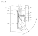
- FIG. 20 shows an eleventh embodiment of the display unit installing structure for a refrigerator according to the present invention
- FIG. 21 shows a side sectional view of the embodiment shown in FIG. 20 .
- a seating groove 38 is provided on the top and/or bottom surface(s) of a display unit 30 .
- the seating groove 38 is formed by depressing a portion of a rear end on the top surface 34 and/or bottom surface 36 in an upward and/or downward direction, respectively.
- the seating groove 38 is preferably formed at a depth corresponding to the sum of thickness of a pair of link members 42 and 44 constructing a link mechanism 40 .
- the link members 42 and 44 are securely seated in the seating groove 38 .
- the link members 42 and 44 are not exposed to the outside. Therefore, the aesthetic sense of the front surface of the refrigerator door 10 is excellent even in a state where the display unit 30 is received in the accommodating unit 12 .
- the configuration of the link mechanism 40 for guiding the withdrawal and accommodation of the display unit 30 and tiltably supporting the withdrawn display unit 30 at a predetermined angle according to this embodiment is the same as that of the fifth embodiment of the present invention.
- a display unit installing structure for a refrigerator according to the present invention so configured has the following advantageous effects.
- the display unit is tiltably supported at a predetermined angle by means of the link mechanism.
- a field of vision can be obtained by tilting the display unit at a predetermined angle depending on user positions, a user can efficiently utilize the display unit.
- the display unit can be retractably received in the accommodating unit, the heat transfer between the interior of the refrigerator and the display unit can be minimized as well as effective heat radiation from the display unit can be achieved. Therefore, the operating reliability of the display unit can be obtained and the efficiency of the refrigerator can also be improved.
- the present invention is configured in such a manner that the front or rear surface of the display unit can be selectively exposed to the outside according to whether the display unit is currently utilized.
- the design of the front external appearance of the door can be diversified, and the aesthetic sense can be consequently enhanced.
- the display unit is received such that its rear surface is exposed to the outside, a component provided on the front surface of the display unit for the information display or operating signal input is not exposed to the outside.
- the display unit can be safely protected against the external shock when the display unit is not used for a long time or when the refrigerator is carried or deposited into storage, the durability thereof can be increased.
- a white board or memo board can be provided on the rear surface of the display unit. Therefore, since a note can be easily made on the white or memo board, a refrigerator can be utilized in various purposes. In addition, since other means used to make a note needs not be installed in a kitchen, the external appearance of the refrigerator and the environment in the kitchen can be neat and clean.
- the display unit is not inadvertently withdrawn from the accommodating unit by using various types of locking means. Therefore, the probability that the display unit may be damaged when the display unit is inadvertently withdrawn from the accommodating unit while using the refrigerator can be avoided.
Abstract
A display unit installing structure for a refrigerator includes an accommodating unit which is formed by depressing a portion on a front surface of a door and in which a display unit for displaying a variety of information thereon and inputting operating signals are retractably installed; a link mechanism for guiding accommodation and withdrawal of the display unit and tiltably supporting the display unit withdrawn from the accommodating unit at a predetermined angle; and a locking arrangement for preventing the display unit from being inadvertently escaping from the accommodating unit. The display unit can be retractably installed on the front surface of the refrigerator door.
Description
The present invention relates to a refrigerator, and more particularly, to a display unit installing structure for a refrigerator which can be used to retractably mount a display unit to a portion on a refrigerator door.
Refrigerators are household appliances for storing foods in a refrigerating or freezing chamber thereof in a refrigerated or frozen state. In addition to a traditional function of storing foods therein, recently available refrigerators are provided with additional devices such as a dispenser and home bar to allow a user to withdraw water or foods stored in the refrigerator without opening the door, so that their convenience of user can be increased. Further, refrigerators may be provided with a display unit on which a variety of information can be displayed and operating signals can be inputted.
As shown in the figure, a main body 1 of a refrigerator is provided with a storage space divided into a refrigerating chamber and a freezing chamber. The refrigerator shown in FIG. 1 is a side-by-side refrigerator in which the freezing and refrigerating chambers are formed from side to side. Such freezing and refrigerating chambers are selectively opened and closed by a freezing chamber door 2 a and a refrigerating chamber door 2 b, respectively.
A dispenser 4 is installed at a portion of the freezing chamber door 2 a. The dispenser 4 allows a user to take water out from the refrigerator without opening the freezing or refrigerating chamber door 2 a or 2 b.
Further, a display unit 6 is mounted to the refrigerating chamber door 2 b. The display unit 6 is used to display information about the refrigerator operation, to output images and sounds or to connect to the Internet. The display unit 6 receives a variety of operating signals required for performing the aforementioned operations. The display unit 6 is fixed to a refrigerator in a state where it is installed in an accommodating unit provided on a front surface of the refrigerating chamber door 2 b.
However, the conventional display unit installing structure for a refrigerator so configured has the following problems.
As described above, the display unit 6 is mounted on the front surface of the refrigerating chamber door 2 b. That is, the display unit is mounted such that a user can have the best field of vision as viewed from the front. Nevertheless, since the display unit is fixed to the front surface of the refrigerating chamber door 2 b, there is a disadvantage in that an inferior filed of vision may be obtained depending on positions of the user.
Further, since the display unit is fixed to the front surface of the refrigerating chamber door 2 b, the external appearance of the refrigerating chamber door 2 b cannot be further changed in a state where the display unit 6 is fixed. Therefore, since there is no possibility of the change in design of the external appearance of the refrigerator, the external appearance of the front surface of the refrigerator becomes monotonous.
In addition, if the display unit 6 is fixed to the front surface of the refrigerating chamber door 2 b, heat generated while the display unit 6 is operated may be transferred to the interior of the refrigerator through the refrigerating chamber door 2 b. Moreover, there is a problem in that it is difficult to release heat from the display unit 6.
Furthermore, the display unit 6 is generally configured in such a manner that it front surface, i.e. a portion thereof in which a liquid crystal is provided, is always directed to the front surface of the door 2 b. Therefore, since the front surface of the display unit 6 is exposed to the outside even when the display unit 6 is not being used for the purpose of transport or storage of the refrigerator, the display unit may be damaged due to external shock or contaminated with foreign substances.
Still furthermore, in a case where a user intends to make a note in a kitchen where the refrigerator is installed, he/she should attach a piece of paper to front or side surfaces of the refrigerator or utilize an additional board or the like.
The present invention is conceived to solve the aforementioned problems in the prior art. Accordingly, an object of the present invention is to provide a display unit installing structure for a refrigerator configured to obtain a better field of vision regardless of positions of a user.
Another object of the present invention is to provide a display unit installing structure for a refrigerator configured such that heat transfer between a display unit and the interior of the refrigerator can be blocked as well as efficient heat radiation from the display unit can be made.
A further object of the present invention is to provide a display unit installing structure for a refrigerator configured such that the design of an external appearance of a refrigerator door can be changed in various ways.
A still further object of the present invention is to provide a display unit installing structure for a refrigerator configured such that a display unit can be safely protected from external shock when the display unit is not used.
A still further object of the present invention is to provide a display unit installing structure for a refrigerator configured to be capable of making a short note thereon.
A still further object of the present invention is to provide a display unit installing structure for a refrigerator configured such that a display unit received in a door can be maintained at a more stable state.
According to an aspect of the present invention for achieving the objects, there is provided a display unit installing structure for a refrigerator, comprising an accommodating unit which is formed by depressing a portion on a front surface of a door and in which a display unit for displaying a variety of information thereon and inputting operating signals are retractably installed, a link mechanism for guiding accommodation and withdrawal of the display unit and tiltably supporting the display unit withdrawn from the accommodating unit at a predetermined angle, and a locking means for preventing the display unit from being inadvertently escaping from the accommodating unit.
The locking means may include at least one locking protrusion provided on one of the accommodating unit and the display unit, and at least one locking groove provided on the other of the accommodating unit and display unit such that the locking protrusion is selectively inserted in the locking groove as the display unit is received in or withdrawn from the accommodating unit.
Preferably, the locking protrusion is shaped as a taper of which diameter is decreased from a base toward a tip end thereof, and the locking groove is shaped as a taper corresponding to the shape of the locking protrusion.
Preferably, the locking protrusion and groove are protruded from a bottom surface of the accommodating unit and depressed into a rear surface of the display unit, respectively, in accordance with a trajectory along which the display unit is received into or withdrawn from the accommodating unit by means of the link mechanism.
The locking means may include a magnet provided at one of the accommodating unit and the display unit to come into close contact with the other of the accommodating unit and the display unit, which are made of metal, due to a magnetic force when the display unit is received in the accommodating unit.
The display unit installing structure may further comprise a guide means for guiding the display unit to be received in the accommodating unit.
The guide means may include at least one pair of guide ribs which are provided on opposite side surfaces of the accommodating unit and brought into close contact with side surfaces of the display unit received in the accommodating unit to support the display unit thereon.
Preferably, the guide rib is formed by protruding a portion of the side surface of the accommodating unit in an opposite direction and a guide surface inclined to be flared outwardly is provided at an outer end of the guide rib to guide the accommodation and withdrawal of the display unit.
The link mechanism may include at least one link member of which both ends are pivotally connected to a bottom surface of the accommodating unit and a rear surface of the display unit, respectively.
The link member may include first and second link members arranged in parallel with each other in a vertical or horizontal direction.
Preferably, each of the first and second link members is a multi-point linkage.
Preferably, both ends of the link member are pivotally connected to a front surface of a bracket detachably installed at the bottom surface of the accommodating unit and a rear surface of a mounting plate fixed to the rear surface of the display unit, respectively.
Preferably, at least one pair of fastening slots are formed on the bottom surface of the accommodating unit to be parallel with and spaced apart from each other by a predetermined distance, and fastening and locking pieces are formed on the rear surface of the bracket to be inserted in the fastening slots, respectively.
Preferably, the fastening piece is formed such that it extends perpendicular to the rear surface of the bracket corresponding to one pair of the fastening slots and a tip portion thereof is then bent to be inclined upward at a predetermined angle, and the locking piece is formed such that it extends perpendicular to the rear surface of the bracket corresponding to the other pair of the fastening slots.
More preferably, at least one positioning protrusion is provided on one of the bottom surface of the accommodating unit or the rear surface of the bracket, and at least one positioning hole is formed in the other of the bottom surface of the accommodating unit or the rear surface of the bracket such that the positioning protrusion can be fitted into the positioning hole only when the bracket is correctly positioned while the bracket is installed on the bottom surface of the accommodating unit.
The display unit installing structure may further comprise a coil spring of which both ends are fixed to the bottom surface of the accommodating unit and the rear surface of the display unit, respectively, and which is maximally stretched at a middle point between a state where the display unit is received and a state where the display unit is fully withdrawn.
Alternatively, the display unit installing structure may further comprise a coil spring of which both ends are fixed to one end of the first link member corresponding to one of the bottom surface of the accommodating unit and the rear surface of the display unit and to one end of the second link member corresponding to the other of the bottom surface of the accommodating unit and the rear surface of the display unit, respectively, and which is maximally stretched at a middle point between a state where the display unit is received and a state where the display unit is fully withdrawn.
Preferably, the accommodating unit is defined by a recess member provided on the front surface of the door.
The display unit installing structure may further comprise a connector capable of tiltably connecting the display unit with respect to the link mechanism.
Preferably, a handle gripped when a user withdraws the display unit from the accommodating unit is provided on a bottom surface of the display unit.
According to another aspect of the present invention, there is provided a display unit installing structure for a refrigerator, comprising an accommodating unit which is formed by depressing a portion on a front surface of a door and in which a display unit for displaying a variety of information thereon and inputting operating signals are retractably installed; a link mechanism for guiding accommodation and withdrawal of the display unit and pivotally supporting the display unit withdrawn from the accommodating unit in a horizontal direction, the link mechanism including at least one pair of first link members of which one end is pivotally connected to the accommodating unit and at least one pair of second link members of which both ends are pivotally connected to a point on a top or bottom surface of the display unit and the other end of the first link member, respectively; and a locking means provided on one side of the accommodating unit and one corresponding side of the display unit to prevent the display unit from being inadvertently escaping from the accommodating unit.
According to a further aspect of the present invention, there is provided a display unit installing structure for a refrigerator, comprising an accommodating unit which is formed by depressing a portion on a front surface of a door and in which a display unit for displaying a variety of information thereon and inputting operating signals are retractably installed; a link mechanism for guiding accommodation and withdrawal of the display unit and pivotally supporting the display unit withdrawn from the accommodating unit in a horizontal direction, the link mechanism including at least one pair of link members of which one end is pivotally connected to the accommodating unit while being movable in a horizontal direction and the other end is pivotally connected to a point on a top or bottom surface of the display unit; and a locking means provided on one side of the accommodating unit and one corresponding side of the display unit to prevent the display unit from being inadvertently escaping from the accommodating unit.
Preferably, a rear surface of the display unit is made of the same material as the front surface of the door.
Preferably, a white board capable of making a note or erasing the note is provided on a rear surface of the display unit.
Preferably, a memo board is provided on a rear surface of the display unit and comprises a base plate formed on the rear surface of the display unit to correspond to the surface shape of the display unit, a film with a rear surface thereof brought into close contact with a front surface of the base plate to allow a user to make a note thereon, and an eraser lever for erasing the note by separating the film from the base plate.
The locking means may comprise a stopper movably installed on one of side surfaces of the accommodating unit and display unit in a direction perpendicular to a direction in which the display unit is received in the accommodating unit, a stopping groove formed on the other of the side surfaces of the accommodating unit and display unit to allow the stopper to be selectively inserted therein, and an elastic member for imparting an elastic force to the stopper in a direction in which the stopper is inserted in the stopping groove.
Preferably, a tip end of the stopper is shaped as a spherical surface such that the stopper does not hinder the display unit from being received in the accommodating unit.
Alternatively, the locking means may comprise an operating lever installed to penetrate the front surface of the door such that a portion of the lever protrudes forward from the door to be movable in a vertical or horizontal direction; a catching protrusion provided on one end of the operating lever such that at least a portion of the catching protrusion is positioned within the accommodating unit; a catching groove formed at a side surface of the display unit such that the catching protrusion can be selectively inserted in the catching groove by moving the operating lever in a state where the display unit is received in the accommodating unit; and an elastic member for imparting an elastic force to the catching protrusion in a direction in which the catching protrusion is inserted in the catching groove.
Preferably, an inclined guide surface is provided on a tip end of the catching protrusion such that the catching protrusion does not hinder the display unit from being received in the accommodating unit.
More preferably, a seating groove is formed on a top and/or bottom surface of the display unit by depressing a portion of a rear end on the top and/or bottom surface in an upward or downward direction, the seating groove is pivotally connected to an end of the link member, and the link mechanism is seated in the seating groove in a state where the display unit is received in the accommodating unit.
According to the present invention so configured, the display unit can be retractably mounted to the front surface of the refrigerator door. Therefore, there are some advantages in that a better field of vision can be substantially obtained enough for a user to view the display unit regardless of positions of the user, the heat transfer between the display unit and the interior of the refrigerator can be blocked, heat radiation efficiency of the display unit can also be improved, the design of the refrigerator door can be provided in various ways, and the display unit can be kept at a more stable state.
Hereinafter, preferred embodiments of a display unit installing structure for a refrigerator according to the present invention will be described in detail with reference to the accompanying drawings.
As shown in these figures, an accommodating unit 12 is provided in a front surface of a refrigerator door 10. The accommodating unit 12 is formed into a flat box with an open front face. In this embodiment, the accommodating unit 12 is defined by a recess member 20 installed on a front surface of the door 10. That is, the recess member 20 is installed on the front surface of the door 10, and thus, the accommodating unit 12 can be defined by a concave portion of the recess member 20. Alternatively, the accommodating unit 12 can be formed integrally with the front surface of the door 10.
A display unit 30 is retractably installed in the accommodating unit 12. Thus, it is preferred that the accommodating unit 12 and the display unit 30 be formed to correspond to each other in view of their shapes. The display unit 30 displays a variety of information to the outside and receives operating signals for performing the information display. For example, the display unit 30 is provided with a function of receiving a television broadcast or connecting to the Internet.
Further, a link mechanism 40 is provided to guide a withdrawing/accommodating motion of the display unit 30. The link mechanism 40 comprises a pair of link members 42 and 44 which are arranged vertically in parallel with each other.
Further, since both ends of the link members 42 and 44 are pivotally connected to a bottom surface of the recess member 20 and a rear surface of the display unit 30, respectively, the link members 42 and 44 can be pivoted on rear ends thereof, respectively, in a vertical direction. Thus, the display unit 30 is moved horizontally due to its vertical pivot motion such that it can be received in and withdrawn from the accommodating unit 12. That is, the display unit 30 is pivoted on supporting points corresponding to the rear ends of the link members 42 and 44 and consequently performs a motion along an arc with a predetermined radius. Although it has not been illustrated herein, it is apparent that the link members 42 and 44 can be configured to be withdrawn from the accommodating unit 12 while the display unit 30 is pivoted in a horizontal direction.
Further, in this embodiment, the link mechanism 40 comprises a pair of link members 42 and 44 each of which is a one-point linkage. Thus, the display unit 30 is withdrawn to the outside to the outside of the accommodating unit 12 while it is being kept at a vertical state. However, if the link mechanism 40 is constructed into a single one-point linkage or configured to include the link members each of which is a multi-point linkage, e.g. a two-point linkage, a tilting angle of the display unit 30 can also be adjusted.
Furthermore, a plurality of locking protrusions 14 are provided on the bottom surface of the accommodating unit 12. Each of the locking protrusions 14 protrudes forward from the bottom surface of the accommodating unit 12 by a predetermined length. A plurality of locking grooves 31 in which the plurality of locking protrusions 14 are fitted are also formed in the rear surface of the display unit 30. Each of the locking grooves 31 is depressed inward in the rear surface of the display unit 30 by a depth equal to the length of the locking protrusion 14.
The locking protrusions and grooves 14 and 31 function to prevent the display unit 30 from being inadvertently withdrawn from the accommodating unit due to the impact, which may be generated during the opening/closing operation of the door 10, when the display unit 30 is received in the accommodating unit 12. To this end, the locking protrusions 14 can be selectively inserted in the locking grooves 31 when the display unit 30 is received in or withdrawn from the accommodating unit 12.
In order to allow the locking protrusions 14 to be inserted in the locking grooves 31 more exactly and smoothly, it is preferred that the locking protrusions and grooves 14 and 31 be tapered such that they can be coupled with each other in the corresponding shapes. That is, as shown in FIG. 3 in a magnified scale, each of the locking protrusions 14 takes the shape of a taper of which diameter is relatively decreased from the base to the tip end. Each of the locking grooves 31 is formed to have a shape corresponding to the shape of the locking protrusion 14.
As shown in FIG. 4 , the four locking protrusions 14 are provided at the corners on the bottom surface of the accommodating unit 12, respectively. Accordingly, the four locking grooves 31 are also provided at the corresponding corners on the rear surface of the display unit 30, respectively.
However, the shapes and positions of the locking protrusions and grooves 14 and 31 are not limited thereto. That is, the locking protrusions and grooves 14 and 31 may be formed in any shapes and at any positions if they can prevent the display unit 30 from being inadvertently withdrawn from the accommodating unit 12 through their mutual coupling.
Although it has been described in this embodiment that the locking protrusions and grooves 14 and 31 are protruded and depressed in a horizontal direction, both of them may be protruded and depressed in a direction corresponding to a trajectory along which the display unit 30 is received in or withdrawn from the accommodating unit 12. That is, the tip end of the locking protrusion 14 may be formed to be upward inclined in harmony with the trajectory of the display unit 30 which is moved along an arc by means of the link mechanism 40. Accordingly, the opening of the locking groove 31 will be formed to be downward inclined in correspondence with the locking protrusion 14.
In addition, a plurality of guide ribs 16 are provided on opposite side surfaces, i.e. upper, lower and lateral side surfaces of the accommodating unit 12. The guide ribs 16 serve to guide and support the display unit 30 to be received in the accommodating unit 12.
To this end, the guide ribs 16 are provided to extend from the bottom surface to the opened front of the accommodating unit 12. Further, the guide ribs 16 protrude from the side surfaces of the accommodating unit 12 in a direction in which they face each other. Therefore, when the display unit 30 is received in the accommodating unit 12, the guide ribs 16 are brought into close contact with the side surfaces of the display unit 30 such that they can support the display unit 30.
At this time, it is preferred that the guide ribs 16 have the same protruding heights as one another, as shown in FIG. 4 . That is, since gaps between the side surfaces of the accommodating unit 12 and the side surfaces of the display unit 30 received therein can be equal to each other, the display unit 30 can be received in an exact position.
In addition, the guide ribs 16 are brought into close contact with the side surfaces of the display unit 30. Accordingly, the display unit cannot be inadvertently withdrawn from the accommodating unit 12, even though an external shock is exerted on the display unit 30 received in the accommodating unit 12.
Furthermore, a guide surface 16 a is provided on an outer end of the guide rib 16. The guide surface 16 a is inclined to be flared outwardly. The guide surface 16 a functions to guide the display unit 30 to a proper position in the accommodating unit 12.
In this embodiment, a pair of guide ribs 16 are provided at each of the side surfaces, i.e. the upper, lower and two lateral surfaces of the accommodating unit 12. But, the number and positions of the guide ribs 16 may be determined in consideration of the sizes of the display unit 30 and the accommodating unit 12.
Next, a second embodiment of a display unit installing structure for a refrigerator according to the present invention will be described with reference to the accompanying drawings.
As shown in the figures, a display unit 30 is retractably installed in an accommodating unit 12 provided on a front surface of a refrigerator door 10. The accommodating unit 12 is defined by a recess member 20 provided on the front surface of the door 10. Further, a link mechanism 40 is provided to guide the accommodation and withdrawal of the display unit 30.
In this embodiment, the link mechanism 40 is composed of first and second link members 42 and 44. Rear ends of the link members 42 and 44 are pivotally connected to a front surface of a bracket 50 provided on a bottom surface of the recess member 20 corresponding to a bottom surface of the accommodating unit 12. Further, front ends of the link members 42 and 44 are pivotally connected to a rear surface of a mounting plate 60 fixed to a rear surface of the display unit 30.
The bracket 50 is detachably installed to the bottom surface of the recess member 20. Further, the mounting plate 60 is fixed to the rear surface of the display unit 30 by means of a plurality of fasteners 61.
In order to install the bracket 50, a plurality of positioning protrusions 21 and fastening slots 23 and 25 are formed on the bottom surface of the recess member 20 corresponding to the bottom surface of the accommodating unit 12. As shown in FIG. 6 , each of the positioning protrusions 21 protrudes forward from and perpendicular to the bottom surface of the recess member 20. Each of the fastening slots 23 and 25 is formed lengthwise in a horizontal direction at both sides of upper and lower portions on the bottom surface of the recess member 20 by cutting out the bottom surface of the recess member 20 at predetermined width and length.
Further, the bracket 50 is formed with positioning holes 51 into which the positioning protrusions 21 are fitted and fastening and locking pieces 53 and 55 which are fitted into the fastening slots 23 and 25. Each of the positioning holes 51 is formed by cutting out a portion of the bracket 50 into a shape corresponding to a cross section of the positioning protrusion 21. Each of the fastening pieces 53 extends rearward from a top end of the bracket 50 and a tip portion thereof is then bent to be inclined upward. Each of the locking pieces 55 extends rearward from a bottom end of the bracket 50 perpendicular to a rear surface of the bracket.
In addition, a pair of fastening holes 27 and a pair of through-holes 57 are formed in the bottom surface of the recess member 20 and the bracket 50 corresponding to the recess member 20, respectively. Fasteners 59 which have passed through the through-holes 57 of the bracket 50 are fastened to the fastening holes 27 of the recess member 20, and consequently, the bracket and recess member are completely coupled with each other.
A process of fixing the bracket to the bottom surface of the recess member 20 corresponding to the bottom surface of the accommodating unit 12 will be explained as follows. First, the fastening pieces 53 are fitted into the upper fastening slots 23 among the fastening slots 23 and 25. At this time, the bracket 50 is positioned to be inclined with respect to the bottom surface of the recess member 20.
The bracket 50 is then pivoted on its upper end where the fastening pieces 53 are provided. Thus, the rear surface of the bracket 50 is brought into close contact with the bottom surface of the recess member 20. At this time, the positioning protrusions 21 are fitted into the positioning holes 51, and the bracket 50 can be then placed in a position. Simultaneously, the locking pieces 55 are fitted into the lower fastening slots 25 among the fastening slots 23 and 25, and the bracket 50 can be finally detachably installed to the bottom surface of the recess member 20. In such a state, the bracket 50 can be completely fixed to the bottom surface of the recess member 20 by using the fasteners 59.
A magnet 70 is provided at a certain position on the rear surface of the display unit 30. In such a case, the bracket 50 is made of iron or steel which can be attracted toward the magnet 70 due to a magnetic force generated from the magnet 70. Thus, if the display unit 30 is received in the accommodating unit 12, the display unit 30 can be kept at a state where it is brought into close contact with the bracket 50 due to the magnetic force generated from the magnet 70. Therefore, it is possible to prevent the display unit 30 from being inadvertently withdrawn from the accommodating unit 12 due to an external shock.
Furthermore, a coil spring 80 is provided to impart an elastic force to the display unit 30 such that the display unit 30 can be received in and withdrawn from the accommodating unit 12. Both ends of the coil spring 80 are fixed to the rear end of the first link member 42 and a front end of the second link member 44, respectively. That is, both ends of the coil spring 80 are fixed to the rear end of the first link member 42 connected to a front surface of the bracket 50 and the front end of the second link member 44 connected to a rear surface of the mounting plate 60, respectively.
Positional relationship between the link members 42 and 44 when the display unit 30 is received or withdrawn will be discussed. As illustrated in a one-dot chain line in FIG. 7 , the first and second link members 42 and 44 are arranged on a straight line when the display unit 30 is received in the accommodating unit 12. As illustrated in a two-dot chain line in FIG. 7 , however, the first and second link members 42 and 44 are arranged in parallel with each other when the display unit 30 is withdrawn from the accommodating unit 12. At this time, the rear end of the first link member 42 and the front end of the second link member 44 are farthest spaced apart from each other.
In other words, the coil spring 80 is maximally stretched at a point where the first and second link members 42 and 44 are arranged in parallel with each other while the display unit 30 is received in or withdrawn from the accommodating unit 12. Further, a distance between the rear end of the first link member 42 and the front end of the second link member 44 is decreased away from such a point while the display unit 30 is received or withdrawn, and thus, a stretched amount of the coil spring 80 is decreased.
Here, a process of causing the display unit 30 to be received or withdrawn will be explained on the assumption that a P point is a point where the rear end of the first link member 42 and the front end of the second link member 44 are farthest spaced apart from each other such that the coil spring 80 can be maximally stretched.
In a state where the display unit 30 is received as illustrated in a one-dot chain line, the coil spring 80 is not stretched. In such a state, if the display unit 30 is pulled forward, the display unit 30 starts to be withdrawn while being pivoted upward and simultaneously moved forward. Therefore, the link members 42 and 44 are pivoted and the coil spring 80 starts to be stretched accordingly.
Further, when the display unit 30 continues to pivoting upward and also moving forward and then reaches the point P, the coil spring 80 is stretched to the utmost. Thus, the coil spring has a maximum elastic restoring force. However, if the display unit 30 passes through the point P due to a withdrawal action, a stretched amount of the coil spring 80 is decreased. From this time on, the elastic restoring force of the coil spring 80 will be exerted on the display unit.
After passing through the point P, therefore, the display unit 30 is subjected to an elastic restoring force of the coil spring 80 and then fully withdrawn from the accommodating unit 12 as shown in a solid line. That is, if a user moves the display unit 30 up to the point P in the process of withdrawing the display unit 30, the display unit 30 can be readily withdrawn due to the elastic restoring force of the coil spring after passing through the point P.
Further, when the display unit 30 is again received in the accommodating unit 12 from a state where the display unit has been withdrawn as shown in a solid line, the elastic restoring force of the coil spring 80 is exerted on the display unit in the same way as the aforementioned withdrawal process. That is, when the display unit 30 is received in the accommodating unit 12, the coil spring 80 is stretched up to the point P. However, after the display unit 30 has passed through the point P, the elastic restoring force of the coil spring 80 assists the display unit 30 in being readily received in the accommodating unit 12.
Hereinafter, a display unit installing structure for a refrigerator according to a third embodiment of the present invention will be explained.
As shown in the figure, a link member 42 of the link mechanism 40 is a two-point linkage. Thus, the link mechanism 40 can guide the accommodation/withdrawal of the display unit 30 and simultaneously adjust the tilting angle of the display unit 30.
Further, the display unit 30 is provided with a handle 31. In the illustrated embodiment, the handle 31 is formed concave by inwardly depressing a portion of a bottom surface of the display unit 30. So long as the handle 31 can be used to allow a user to pull the display unit 30 received in the accommodating unit 12 with his/her hand, it can formed in any shape.
Further, the other configuration for accommodating and/or withdrawing the display unit 30, including the accommodating unit 12, the recess member 20, the bracket 50 and the mounting plate 60, is the same as that of the second embodiment of the present invention.
Meanwhile, FIG. 9 shows a fourth embodiment of a display unit installing structure for a refrigerator according to the present invention, and FIGS. 10 and 11 show an operating mode of the display unit installing structure of the embodiment shown in FIG. 8 .
As shown in these figures, in this embodiment, a connector 70 is provided between the display unit 30 and a front end of the link mechanism 40. The display unit 30 can be tilted with respect to the front end of the link mechanism 40 by means of the connector 70.
More specifically, the mounting plate 60 is fixed to a rear surface of the display unit 30. The connector 70 is installed to the rear surface of the mounting plate 60 such that it can be tilted in a horizontal direction. The front end of the link mechanism 40 is pivotally connected to the connector 70. A rear end of the link mechanism 40 is pivotally connected to a front surface of the bracket 50. According to this embodiment, therefore, the display unit 30 can be tilted by means of the link mechanism 40 in a vertical direction and by means of the connector 70 in a horizontal direction.
Next, a fifth embodiment of a display unit installing structure for a refrigerator will be described in detail with reference to the accompanying drawings.
As shown in these figures, an accommodating unit 12 provided on the front surface of the door 10 and a display unit 30 retractably installed to the accommodating unit 12 are the same as those described in the first embodiment of the present invention. A rear surface 32 of the display unit 30 is made of the same material as that of the front surface of the door 10.
In this embodiment, a link mechanism 40 is provided to guide the withdrawal and accommodation of the display unit 30 and to pivotally support the display unit 30 on a horizontal surface. As shown in FIG. 13 , the link mechanism 40 is composed of a pair of link members 42 and 44 symmetrical with each other. Further, both ends of the link member 42 or 44 are pivotally connected to the accommodating unit 12 and the display unit 30, respectively.
The rear ends of 42 a and 44 a of the link members 42 and 44 are pivotally connected to an inner side of the accommodating unit 12, preferably a ceiling surface 14 and/or bottom surface 16 of the accommodating unit 12. At this time, the rear ends 42 a and 44 a of the link members 42 and 44 are supported such that they can be tilted in a horizontal direction. For example, the rear ends 42 a and 44 a of the link members 42 and 44 may be installed in a pair of rail grooves 18 and 19 with a predetermined length, respectively, such that they can be slid along the grooves which are formed symmetrically in a horizontal direction on the ceiling surface 14 and/or bottom surface 16 of the accommodating unit 12.
Although it has not been illustrated in the figures, the rear ends 42 a and 44 a of the link members 42 and 44 may be configured to be slid in a horizontal direction within the interior of the door 10 corresponding to the interior or rear of the accommodating unit 12.
The front ends 42 a and 44 a of the link members 42 and 44 are pivotally connected to a top surface 34 and/or a bottom surface 36 of the display unit 30, respectively. As shown in FIG. 13 , the front ends 42 a and 44 a of the link members 42 and 44 are pivotally hinged or pin-connected on a point on the top and/or bottom surface 34 and 36 of the display unit 30, preferably a middle point on the surface in a horizontal direction. Since the front ends 42 a and 44 a of the link members 42 and 44 are pivotally connected to a point on the top and/or bottom surface 34 and 36 of the display unit 30 as described above, the display unit 30 can be substantially pivoted on a single point to which the front ends 42 a and 44 a of the link members 42 and 44 are connected.
Next, a process of operating the display unit using the display unit installing structure for a refrigerator according to the fifth embodiment of the present invention will be explained in detail with reference to FIG. 14 .
When the display unit 30 is withdrawn from the accommodating unit 12 as shown in FIG. 14 (b), the display unit 30 can be pivoted clockwise or counterclockwise in a horizontal direction on the middle point to which the front ends of the link mechanism 40 are connected.
Therefore, in a case where the display unit is not utilized for a long time to carry a refrigerator or deposit a refrigerator in storage, the display unit 30 is rotated clockwise or counterclockwise in a horizontal direction as shown in FIG. 14 (c). Thus, the rear surface 32 of the display unit 30 is exposed to the outside.
Further, FIG. 14 (d) illustrates a state where the display unit 30 is again pushed and received in the accommodating unit 12 in a state shown in FIG. 14 (c). That is, the rear surface 32 of the display unit 30 is exposed to the outside in a state where it is coplanar with the front surface of the door 10.
Furthermore, the rear surface 32 of the display unit 30 is made of the same material as that of the front surface of the door 10. Therefore, the display unit 30 that is not utilized for a while can be protected, and its aesthetic function can also be improved since the front surface of the door 10 can be planar and smooth.
Meanwhile, when the display unit 30 is withdrawn from the accommodating unit 12 as shown in FIG. 14 (b), the display unit 30 can be substantially pivoted in a horizontal direction. Therefore, since the display unit 30 can be tilted at a certain angle in a horizontal direction depending on the position of a user, a wide field of vision can be obtained.
As described above, the rear surface 32 of the display unit 30 is made of the same material as that of the door 10 in this embodiment. Thus, as shown in FIG. 14 (d), an external appearance of the front surface of the door 10 provides an integral sense of feeling in a state where the display unit 30 is received in the accommodating unit 12 such that its rear surface 32 is exposed to the outside.
However, the configuration of the rear surface 32 of the display unit 30 is not limited thereto. For example, a white board 32 can be provided on the rear surface of the display unit 30 as illustrated in a sixth embodiment of the present invention shown in FIG. 15 . A user can make a note on the white board using a specific writing tool or erase the note. Therefore, a user can make a note on the white board 32 in a state where the display unit 30 is received in the accommodating unit 12 such that the rear surface thereof is exposed to the outside.
In a seventh embodiment of the present invention shown in FIG. 16 , a memo board 32 is also provided on a rear surface of the display unit 30. The memo board 32 is composed of a base plate formed on the rear surface of the display unit 30 to correspond to the surface shape of the display unit 30, a synthetic resin film of which a rear surface is brought into close contact with a front surface of the base plate to allow a user to make a note thereon, and an eraser lever 34 for erasing the written note by separating the film from the base plate.
That is, when a pressure is exerted on a front surface of the synthetic resin film using a writing tool, a portion of the synthetic resin film to which the pressure is exerted is brought into close contact with the front surface of the base plate to thereby write a note thereon. Then, the note can be erased by separating the synthetic resin film and the base plate which have been brought into close contact with each other by said eraser lever 34.
In this embodiment, a link mechanism 40 is composed of first and second link members 42 and 44 each of which is a two-point link. Rear ends of the link members 42 and 44 are pivotally connected to the accommodating unit 12. Preferably, the rear ends of the link members 42 and 44 are connected to the ceiling surface 14 and/or bottom surface 16 of the accommodating unit 12. At this time, positions to which the rear ends of the link members 42 and 44 are connected are symmetric with the horizontal middle point on the ceiling surface 14 and/or bottom surface 16 of the accommodating unit 12. Further, front ends of the link members 42 and 44 are also pivotally connected to the horizontal middle point on the top surface 34 and/or bottom surface 36 of the display unit 30. Therefore, by means of the link mechanism 40, the display unit 30 can be withdrawn from the accommodating unit 12 or tilted in a horizontal direction in a state where the display unit has been withdrawn from the accommodating unit.
As shown in the figure, an accommodating unit 12 is provided at a front surface of the refrigerator door 10. The accommodating unit 12 is defined by a recess member 20. Further, the recess member 20 is installed at the front surface of the door 10. At this time, both surfaces of an outer part defining a front external appearance of the door 10 and the recess member 20 are spaced apart by a predetermined distance from each other to create an operating space S therebetween.
Further, installation grooves 14 are provided, respectively, at both side surfaces of the recess member 20 corresponding to both side surfaces of the accommodating unit 12. Each of the installation grooves 14 is formed by depressing a portion of the side surface of the recess member 20 inward into the operating space S. A through-hole 16 is formed through a portion of an inner side of the installation groove 14.
The display unit 30 is received in the accommodating unit 12. Further, a locking means is provided to prevent the display unit 30 received in the accommodating unit 12 from being inadvertently withdrawn due to an external shock. The locking means includes a stopper 51, a stopping groove 31 in which the stopper 51 is inserted, and a coil spring 55 that imparts an elastic force to the stopper 51.
The stopper 51 is installed through the through-hole 16. Thus, the stopper 51 should have a relatively small outer diameter as compared with an inner diameter of the through-hole 16. A tip end of the stopper 51 is located within the accommodating unit 12. Further, a rear end of the stopper 51 is located within the installation space S.
A catching protrusion 52 is provided at the tip end of the stopper 51 which is located within the accommodating unit 12. The catching protrusion 52 is a portion which is substantially inserted in the stopping groove 31. Further, a catching flange 53 is provided at the rear end of the stopper 51 which is located within the operating space S. Each of the catching protrusion 52 and the catching flange 53 has a relatively large diameter as compared with that of the through-hole 16.
When it is inserted in the installation groove 14, the stopper 51 allows the display unit 30 to move in a direction perpendicular to a direction in which the display unit 30 is received into the accommodating unit 12. In this embodiment, since the stoppers 51 are installed, respectively, at both side surfaces of the recess members 20, they can be moved in a right and left direction as viewed from this figure.
The stopping grooves 31 are formed at positions on both side surfaces of the display unit 30 corresponding to the stoppers 51, respectively. Each of the stopping grooves 31 is formed by inward depressing a portion on the side surface of the display unit 30. The stopping groove 31 is formed to have a shape corresponding to the catching protrusion 52.
In this embodiment, both the catching protrusion 52 provided at the tip end of the stopper 51 and the corresponding stopping grove 31 are shaped as a spherical surface. This is because the stopper 51 can be easily inserted in or detached from the stopping groove 31 as well as the withdrawal/accommodation of the display unit 30 cannot be hindered by the stopper 51. However, the shapes of the catching protrusion 52 and the stopping groove 31 are not limited to a spherical shape. For example, even though the catching protrusion 52 and the stopping groove 31 are shaped as corresponding conical shapes that are complementary to each other, the aforementioned effects may be expected.
The coil spring 55 imparts an elastic force to the stopper 51 in a direction in which the stopper 51 is inserted into the stopping groove 31. The coil spring 55 is installed to surround the stopper 51 in a state where both ends thereof are supported on an inner surface of the installation groove 14 and one side of the supporting protrusion 52, respectively. The coil spring 55 prevents the stopper 51 from being inadvertently escaped from the stopping groove 31.
In this embodiment, the stopper 51 and the stopping groove 31 are installed at each of the two side surfaces of the recess member 20 and each of the two side surfaces of the display unit 30, respectively. However, the stopper 51 and the stopping groove 31 may be installed at each of the two side surfaces and/or the top and bottom surfaces of the recess member 20 and the display unit 30, respectively. The number of the stoppers 51- and stopping grooves 31 may be greater or lower than two (2) depending on the size and shape of the accommodating unit 12 or the display unit 30.
Now, the operation of the stopper 51 when the display unit 30 is withdrawn or received will be explained. In a state where the display unit 30 is received in the accommodating unit 12, the stopper 51 is inserted in the stopping groove 31. At this time, the stopper 51 cannot be inadvertently escaped from the stopping groove 31 due to the elastic force of the coil spring 55.
Therefore, even though an external force is applied to the display unit 30 while the refrigerator door is opened or closed, the display unit 30 is not inadvertently withdrawn from the accommodating unit 12. Further, the vibration generated when the door 10 is opened or closed can also be absorbed by means of the elasticity of the coil spring 55.
If a user pulls forward the display unit 30 to withdraw the display unit 30 from the accommodating unit 12 in such a state, the stopper 51 starts to be escaped from the stopping groove 31. At this time, since the stopper 51 and the stopping groove 31 are shaped as a mutually corresponding spherical surface, the stopper 51 can be easily escaped from the stopping groove 31.
The stopper 51 which has been escaped from the stopping groove 31 is pushed into the installation groove 14 by means of both side surfaces of the display unit 30. At this time, the coil spring 55 is in a compressed state. Further, after the display unit 30 has been completely withdrawn from the accommodating unit 12, the stopper 51 again protrudes from the installation groove 14, i.e. into the accommodating unit 12.
The process of receiving the display unit 30 again into the accommodating unit 12 is performed in a reverse order to the aforementioned withdrawal process. That is, if a user pushes the display unit 30 rearward into the accommodating unit 12 to receive the former into the latter, the stopper 51 is pushed unto the accommodating unit 12 by means of the display unit 30. At this time, since the catching protrusion 52 is shaped as a spherical surface, the accommodation of the display unit 30 is not hindered by the stopper 51.
Further, after the display unit 30 has been completely received in the accommodating unit 12, the stopper 51 protrudes again into the accommodating unit 12 due to the elastic force of the coil spring 55 and is then inserted in the stopping groove 31. Thus, the display unit 30 cannot be inadvertently escaped from the accommodating unit 12.
In the meantime, FIG. 19 shows a tenth embodiment of a display unit installing structure for a refrigerator according to the present invention.
As shown in this figure, a recess member 20 defining an accommodating unit 12 is installed on a front surface of the refrigerator door 10. A display unit 30 is installed in the accommodating unit 12 such that it can be received or withdrawn by means of a link mechanism 40. In addition, an operating space S is provided between an outer part defining a front external appearance of the door 10 and both side surfaces of the recess member 20. Further, an installation groove 14 is formed on each of the side surfaces of the recess member 20 by depressing a portion of the side surface of the recess member inward into the operating space S. A through-hole 16 is formed through an inner surface of the installation groove 14. The configuration of this embodiment is the same as that of the ninth embodiment of the present invention.
In the meantime, a slot 13 is formed in the front surface of the door 10 corresponding to a front face of the operating space S. The slot 13 is formed by cutting out a portion on a front surface of the recess member 20 by a predetermined length in a horizontal direction.
An operating lever 61 is provided to prevent the display unit 30 from being inadvertently withdrawn from the accommodating unit 12 due to an external shock. The operating lever 61 is L-shaped. The operating lever 61 is positioned within the operating space S and the installation groove 14. Further, both ends of the operating lever 61 pass through the slot 13 and the through-hole 16, respectively, to protrude forward from the door 10 and into the accommodating unit 12.
The operating lever 61 is installed to be movable in a horizontal direction along the slot 13. To this end, an operating grip 62 is provided at one end of the operating lever 61 which protrudes forward through the door 10 to the outside. The operating grip 62 is a portion which a user grip and manipulates to move the operating lever 61. The operating grip 62 is sized not be introduced into the operating space S through the slot 13.
In this embodiment, the operating lever 61 is provided at both side surfaces of the recess member 20 corresponding to both sides of the accommodating unit 12. However, the operating lever 61 may be provided at top and bottom surfaces of the recess member 12. In such a case, the operating grip 62 will be moved in a vertical direction.
Meanwhile, a catching protrusion 63 is provided at the other end of the operating lever 61 which protrudes into the accommodating unit 12. The catching protrusion 63 is sized not to be introduced into the operating space S through the through-hole 16. An inclined guide surface 64 is provided on a tip end of the catching protrusion 63. The inclined guide surface 64 is formed to be flared toward the outside. The inclined guide surface 64 serves to prevent the display unit 30 from being hindered by the catching protrusion 63 when the display unit 30 is received into the accommodating unit 12.
In addition, a catching groove 31 is formed on both side surfaces of the display unit 30. The catching protrusion 63 is selectively inserted in the catching groove 31 by means of the horizontal motion of the operating lever 61. That is, the catching protrusion 63 is kept to be inserted in the catching groove 31 when the display unit 30 is received in the accommodating unit 12. Due to the horizontal motion of operating grip, the display unit 30 can be withdrawn from the accommodating unit 12.
Further, a coil spring 65 is provided to impart an elastic force to the operating lever 61 in a direction in which the catching protrusion 63 is inserted in the catching groove 31. The coil spring 65 is installed to surround a portion of the operating lever 61. At this time, both ends of the coil spring 65 are supported on an inner side surface of the installation groove 14 and a surface of the catching protrusion 63. Due to the elastic force of the coil spring 65, therefore, the catching protrusion 63 cannot be inadvertently escaped from the catching groove 31.
Furthermore, the operation of the operating lever 61 when the display unit 30 is received in or withdrawn from the accommodating unit 12 will be discussed. In a state where the display unit 30 is received in the accommodating unit 12, the catching protrusion 63 is kept to be inserted in the catching groove 31. At this time, due to the elastic force of the coil spring 65, the catching protrusion 63 cannot be inadvertently escaped from the catching groove.
Therefore, even though an external shock is generated while the refrigerator door is opened or closed, the display unit 30 is not inadvertently withdrawn from the accommodating unit 12. Further, the vibration generated while the door 10 is opened or closed can be absorbed due to the elasticity of the coil spring 65.
If a user merely moves the two operating grips 62 far away from each other, i.e. in a horizontal direction, along the slot 13 in such a state, the display unit 30 is withdrawn from the accommodating unit 12. At this time, the operating lever 61 and the catching protrusion 63 are moved in the same direction as the operating grip 62. Thus, the catching protrusion 63 is escaped from the catching groove 31 and then positioned within the installation groove 14.
If the catching protrusion 63 is escaped from the catching groove 31 in this way, the display unit 30 can be withdrawn from the accommodating unit 12. After the display unit 30 is completely withdrawn from the accommodating unit 12, a force needed for moving the operating grip 62 is eliminated. Thus, the catching protrusion 63 again protrudes from the installation groove into the accommodating unit 12 due to the elastic force of the coil spring 65.
Next, an eleventh embodiment of a display unit installing structure for a refrigerator according to the present invention will be described in detail with reference to the accompanying drawings.
In this embodiment as shown in these figures, a seating groove 38 is provided on the top and/or bottom surface(s) of a display unit 30. The seating groove 38 is formed by depressing a portion of a rear end on the top surface 34 and/or bottom surface 36 in an upward and/or downward direction, respectively. The seating groove 38 is preferably formed at a depth corresponding to the sum of thickness of a pair of link members 42 and 44 constructing a link mechanism 40.
As shown in FIG. 21 , in a state where the display unit 30 is received in the accommodating unit 12, the link members 42 and 44 are securely seated in the seating groove 38. Thus, the link members 42 and 44 are not exposed to the outside. Therefore, the aesthetic sense of the front surface of the refrigerator door 10 is excellent even in a state where the display unit 30 is received in the accommodating unit 12.
The configuration of the link mechanism 40 for guiding the withdrawal and accommodation of the display unit 30 and tiltably supporting the withdrawn display unit 30 at a predetermined angle according to this embodiment is the same as that of the fifth embodiment of the present invention.
It is apparent to those skilled in the art that various modifications and changes can be made to the present invention within the scope of the basic technical spirit of the present invention. Therefore, the present invention should be construed as defined in the appended claims.
As described above, a display unit installing structure for a refrigerator according to the present invention so configured has the following advantageous effects.
First, the display unit is tiltably supported at a predetermined angle by means of the link mechanism. Thus, since a field of vision can be obtained by tilting the display unit at a predetermined angle depending on user positions, a user can efficiently utilize the display unit.
In addition, since the display unit can be retractably received in the accommodating unit, the heat transfer between the interior of the refrigerator and the display unit can be minimized as well as effective heat radiation from the display unit can be achieved. Therefore, the operating reliability of the display unit can be obtained and the efficiency of the refrigerator can also be improved.
Further, the present invention is configured in such a manner that the front or rear surface of the display unit can be selectively exposed to the outside according to whether the display unit is currently utilized. Thus, the design of the front external appearance of the door can be diversified, and the aesthetic sense can be consequently enhanced.
Furthermore, as described above, if the display unit is received such that its rear surface is exposed to the outside, a component provided on the front surface of the display unit for the information display or operating signal input is not exposed to the outside. Thus, since the display unit can be safely protected against the external shock when the display unit is not used for a long time or when the refrigerator is carried or deposited into storage, the durability thereof can be increased.
In the meantime, a white board or memo board can be provided on the rear surface of the display unit. Therefore, since a note can be easily made on the white or memo board, a refrigerator can be utilized in various purposes. In addition, since other means used to make a note needs not be installed in a kitchen, the external appearance of the refrigerator and the environment in the kitchen can be neat and clean.
Finally, the display unit is not inadvertently withdrawn from the accommodating unit by using various types of locking means. Therefore, the probability that the display unit may be damaged when the display unit is inadvertently withdrawn from the accommodating unit while using the refrigerator can be avoided.
Claims (3)
1. A display unit installing structure for a refrigerator, comprising:
an accommodating unit which is formed by depressing a portion on a front surface of a door and in which a display unit for displaying a variety of information thereon and inputting operating signals are retractably installed;
a link mechanism for guiding accommodation and withdrawal of the display unit and tiltably supporting the display unit withdrawn from the accommodating unit at a predetermined angle; and
a locking means for preventing the display unit from inadvertently escaping from the accommodating unit; and
a guide means for guiding the display unit to be received in the accommodating unit,
wherein the locking means includes:
at least one locking protrusion provided on one of the accommodating unit and the display unit; and
at least one locking groove provided on the other of the accommodating unit and display unit such that the locking protrusion is selectively inserted in the locking groove as the display unit is received in or withdrawn from the accommodating unit,
wherein the locking protrusion is shaped as a taper of which diameter is decreased from a base toward a tip end thereof, and the locking groove is shaped as a taper corresponding to the shape of the locking protrusion,
wherein the locking protrusion and groove are protruded from a bottom surface of the accommodating unit and depressed into a rear surface of the display unit, respectively, in accordance with a trajectory along which the display unit is received into or withdrawn from the accommodating unit by means of the link mechanism,
wherein the guide means includes at least one pair of guide ribs which are provided on opposite side surfaces of the accommodating unit and brought into close contact with side surfaces of the display unit received in the accommodating unit to support the display unit thereon, and
wherein the guide ribs are formed by protruding a portion of the side surface of the accommodating unit in a direction toward the opposite side surfaces, and a guide surface inclined to be flared outwardly is provided at an outer end of the guide rib to guide the accommodation and withdrawal of the display unit.
2. The display unit installing structure as claimed in claim 1 , wherein the link mechanism includes at least one link member of which both ends are pivotally connected to a bottom surface of the accommodating unit and a rear surface of the display unit, respectively.
3. The display unit installing structure as claimed in claim 2 , wherein the link member is composed of first and second link members arranged in parallel with each other in a vertical or horizontal direction.
Applications Claiming Priority (25)
| Application Number | Priority Date | Filing Date | Title |
|---|---|---|---|
| KR1020040112360A KR20060073226A (en) | 2004-12-24 | 2004-12-24 | Display mounting structure for refrigerator |
| KR10-2004-0112360 | 2004-12-24 | ||
| KR10-2004-0112358 | 2004-12-24 | ||
| KR1020040112361A KR20060073227A (en) | 2004-12-24 | 2004-12-24 | Device for supporting display to door of refrigerator |
| KR10-2004-0112359 | 2004-12-24 | ||
| KR1020040112359A KR20060073225A (en) | 2004-12-24 | 2004-12-24 | Display mounting structure for refrigerator |
| KR10-2004-0112361 | 2004-12-24 | ||
| KR1020040112358A KR100779526B1 (en) | 2004-12-24 | 2004-12-24 | Display mounting structure for refrigerator |
| KR1020040113279A KR100608939B1 (en) | 2004-12-27 | 2004-12-27 | Display mounting structure for refrigerator |
| KR10-2004-0113279 | 2004-12-27 | ||
| KR1020040115744A KR100582075B1 (en) | 2004-12-29 | 2004-12-29 | Display mounting structure for refrigerator |
| KR10-2004-0115744 | 2004-12-29 | ||
| KR10-2005-0008111 | 2005-01-28 | ||
| KR1020050008111A KR101065521B1 (en) | 2005-01-28 | 2005-01-28 | Device for supporting display to door of refrigerator |
| KR10-2005-0008109 | 2005-01-28 | ||
| KR1020050008109A KR100582068B1 (en) | 2005-01-28 | 2005-01-28 | Display mounting structure for refrigerator |
| KR1020050008724A KR101143700B1 (en) | 2005-01-31 | 2005-01-31 | Device for supporting display to door of refrigerator |
| KR10-2005-0008722 | 2005-01-31 | ||
| KR1020050008777A KR100608953B1 (en) | 2005-01-31 | 2005-01-31 | Device for supporting display to door of refrigerator |
| KR1020050008722A KR101143655B1 (en) | 2005-01-31 | 2005-01-31 | Device for supporting display to door of refrigerator |
| KR10-2005-0008723 | 2005-01-31 | ||
| KR10-2005-0008724 | 2005-01-31 | ||
| KR10-2005-0008777 | 2005-01-31 | ||
| KR1020050008723A KR101143677B1 (en) | 2005-01-31 | 2005-01-31 | Device for supporting display to door of refrigerator |
| PCT/KR2005/004513 WO2006068456A1 (en) | 2004-12-24 | 2005-12-23 | Display unit installing structure for refrigerator |
Publications (2)
| Publication Number | Publication Date |
|---|---|
| US20070290588A1 US20070290588A1 (en) | 2007-12-20 |
| US7967404B2 true US7967404B2 (en) | 2011-06-28 |
Family
ID=36602005
Family Applications (1)
| Application Number | Title | Priority Date | Filing Date |
|---|---|---|---|
| US11/722,795 Expired - Fee Related US7967404B2 (en) | 2004-12-24 | 2005-12-23 | Display unit installing structure for refrigerator |
Country Status (5)
| Country | Link |
|---|---|
| US (1) | US7967404B2 (en) |
| EP (1) | EP1831623A4 (en) |
| BR (1) | BRPI0519392B1 (en) |
| MX (1) | MX2007007603A (en) |
| WO (1) | WO2006068456A1 (en) |
Cited By (3)
| Publication number | Priority date | Publication date | Assignee | Title |
|---|---|---|---|---|
| US20110163215A1 (en) * | 2005-10-03 | 2011-07-07 | Peerless Industries, Inc. | Pull-Out Swivel Mount |
| US20200097050A1 (en) * | 2018-09-24 | 2020-03-26 | Apple Inc. | Accessory devices for portable electronic devices |
| US10830524B2 (en) * | 2012-10-12 | 2020-11-10 | Toshiba Lifestyle Products & Services Corporation | Refrigerator configured for interaction with portable information terminal |
Families Citing this family (34)
| Publication number | Priority date | Publication date | Assignee | Title |
|---|---|---|---|---|
| KR100638901B1 (en) * | 2004-12-14 | 2006-10-26 | 엘지전자 주식회사 | Display of tiliting Assembly |
| CN201012025Y (en) * | 2006-11-24 | 2008-01-30 | 吴槐 | Rotating link mechanism of the wall-hanging double-arm rack |
| US20080123284A1 (en) * | 2006-11-29 | 2008-05-29 | Dell Products, Lp | Server rack door mounted display assembly |
| US7798865B2 (en) | 2007-01-04 | 2010-09-21 | Whirlpool Corporation | Service supply module and adapter for a consumer electronic device |
| WO2008086132A2 (en) * | 2007-01-04 | 2008-07-17 | Whirlpool Corporation | Host and adapter for selectively positioning a consumer electronic device |
| US7870753B2 (en) | 2007-01-04 | 2011-01-18 | Whirlpool Corporation | Appliance door with a service interface |
| US7865639B2 (en) | 2007-01-04 | 2011-01-04 | Whirlpool Corporation | Appliance with an electrically adaptive adapter to alternatively couple multiple consumer electronic devices |
| US7980088B2 (en) | 2007-01-04 | 2011-07-19 | Whirlpool Corporation | Removable adapter providing a wireless service to removable consumer electronic device |
| US7651368B2 (en) | 2007-01-04 | 2010-01-26 | Whirpool Corporation | Appliance with an adapter to simultaneously couple multiple consumer electronic devices |
| US7618295B2 (en) | 2007-01-04 | 2009-11-17 | Whirlpool Corporation | Adapter and consumer electronic device functional unit |
| US8040666B2 (en) | 2007-01-04 | 2011-10-18 | Whirlpool Corporation | Door with a service interface on an edge |
| US8018716B2 (en) | 2007-01-04 | 2011-09-13 | Whirlpool Corporation | Adapter for docking a consumer electronic device in discrete orientations |
| US8154857B2 (en) * | 2007-01-04 | 2012-04-10 | Whirlpool Corporation | Appliance host with multiple service interfaces for coupling multiple consumer electronic devices |
| US7810343B2 (en) | 2007-01-04 | 2010-10-12 | Whirlpool Corporation | Dispenser with a service interface for a consumer electronic device |
| US7869201B2 (en) | 2007-01-04 | 2011-01-11 | Whirlpool Corporation | Host and adapter for selectively positioning a consumer electronic display in visible and concealed orientations |
| US7826203B2 (en) | 2007-01-04 | 2010-11-02 | Whirlpool Corporation | Transformative adapter for coupling a host and a consumer electronic device having dissimilar standardized interfaces |
| US7898812B2 (en) | 2007-01-04 | 2011-03-01 | Whirlpool Corporation | Alternative hosts for multiple adapters and multiple consumer electronic devices |
| US7765332B2 (en) | 2007-01-04 | 2010-07-27 | Whirlpool Corporation | Functional adapter for a consumer electronic device |
| US7871300B2 (en) | 2007-01-04 | 2011-01-18 | Whirlpool Corporation | Host with multiple sequential adapters for multiple consumer electronic devices |
| US7686127B2 (en) | 2007-01-04 | 2010-03-30 | Whirlpool Corporation | Acoustic chamber as part of adapter or appliance |
| US7800893B2 (en) * | 2007-04-11 | 2010-09-21 | Hewlett-Packard Development Company, L.P. | Display stabilization system |
| US8675354B2 (en) * | 2007-06-27 | 2014-03-18 | Voxx International Corporation | Multi-media memo board |
| US8276399B2 (en) | 2007-09-12 | 2012-10-02 | Whirlpool Corporation | Docking station for a refrigerator |
| WO2009152054A1 (en) * | 2008-06-11 | 2009-12-17 | Peerless Industries, Inc. | Mount for moving of a display |
| TWM410827U (en) * | 2011-03-23 | 2011-09-01 | ming-xian Huang | Hanging base capable of regulating angle, and monitor fastening rack having hanging base capable of regulating angle |
| KR102220809B1 (en) * | 2013-08-22 | 2021-02-26 | 삼성전자주식회사 | Refrigerator |
| JP6335615B2 (en) * | 2014-04-25 | 2018-05-30 | キヤノン株式会社 | Image forming apparatus |
| JP2017026169A (en) * | 2015-07-16 | 2017-02-02 | シャープ株式会社 | Electrical household appliance and refrigerator |
| US10624219B2 (en) * | 2016-10-31 | 2020-04-14 | Michael Sisson | Interactive cabinetry door for use with a cabinet base |
| US11006788B2 (en) * | 2016-11-11 | 2021-05-18 | Trevor Thomas | Product dispenser with active media display |
| KR20180068072A (en) * | 2016-12-13 | 2018-06-21 | 삼성전자주식회사 | Refrigerator |
| CN109084154B (en) * | 2018-10-17 | 2020-08-07 | 蚌埠市宝莱德智能科技有限公司 | Liquid crystal display screen |
| KR20210050128A (en) * | 2019-10-28 | 2021-05-07 | 삼성전자주식회사 | Refrigerator |
| CN112212141A (en) * | 2020-09-21 | 2021-01-12 | 黄国清 | Fixing device of wall-hanging machine case for network engineering |
Citations (40)
| Publication number | Priority date | Publication date | Assignee | Title |
|---|---|---|---|---|
| US419521A (en) * | 1890-01-14 | Mirror supporting and adjusting device | ||
| US1830308A (en) * | 1928-02-29 | 1931-11-03 | Gustav P Zepke | Extensible support for fixtures |
| US2825152A (en) * | 1954-10-18 | 1958-03-04 | Charles A Baylon | Wall-mounted information display panel structure |
| US3113996A (en) * | 1962-02-02 | 1963-12-10 | Roy S Sanford | Article support |
| US4814759A (en) * | 1987-07-08 | 1989-03-21 | Clinicom Incorporated | Flat panel display monitor apparatus |
| US5321579A (en) * | 1991-07-19 | 1994-06-14 | Teknion Furniture Systems | Office panelling system with a monitor screen mounted on a cantilevered adjustable arm |
| JPH0898116A (en) | 1994-09-28 | 1996-04-12 | Okamura Corp | Supporting device for television receiver and the like |
| CN1257353A (en) | 1998-07-07 | 2000-06-21 | 日本电气株式会社 | Portable instrument holder |
| JP2001215078A (en) | 2000-02-01 | 2001-08-10 | Lg Electronics Inc | Installing angle regulator of liquid crystal display device for refrigerator |
| US20010052741A1 (en) * | 2000-06-19 | 2001-12-20 | Lg Electronics Inc | Installation structure for display unit of refrigerator |
| KR20020029506A (en) | 2000-10-13 | 2002-04-19 | 윤종용 | Refrigerator equipped monitor apparatus |
| US6430946B2 (en) * | 2000-03-30 | 2002-08-13 | Lg Electronics Inc. | Structure for mounting monitor on refrigerator |
| US20030154673A1 (en) | 2002-02-15 | 2003-08-21 | Macgregor Bruce G. | Partition panel with modular appliance mounting arrangement |
| WO2004002282A2 (en) | 2002-06-12 | 2004-01-08 | Wegrzecki Lester L | Mirror with slidable set |
| DE202004012298U1 (en) | 2004-04-26 | 2004-09-30 | BSH Bosch und Siemens Hausgeräte GmbH | Household appliance with swiveling display screen |
| US20040216471A1 (en) | 2003-03-10 | 2004-11-04 | Kim Jung Ho | Refrigerator |
| KR100464265B1 (en) | 2004-06-03 | 2005-01-03 | 코스텔(주) | Reclamated multi functional television device |
| KR20050011726A (en) | 2003-07-23 | 2005-01-29 | 가부시끼가이샤 르네사스 테크놀로지 | Display drive control device, for which drive method, electronics device and semiconductor integrated circuit |
| US6905101B1 (en) * | 2002-06-11 | 2005-06-14 | Chief Manufacturing Inc. | Adjustable, self-balancing flat panel display mounting system |
| KR20050058151A (en) | 2003-12-11 | 2005-06-16 | 엘지전자 주식회사 | Communication pad mounting structure for internet refrigerator |
| CN1683854A (en) | 2004-04-12 | 2005-10-19 | 乐金电子(天津)电器有限公司 | Lock structure of refrigerator display |
| WO2005120053A1 (en) | 2004-06-03 | 2005-12-15 | Costel Co., Ltd. | In-wall type multi-functional television set |
| KR20060011726A (en) | 2004-07-31 | 2006-02-03 | 엘지전자 주식회사 | Refrigerator mounted with display device |
| KR20060011727A (en) | 2004-07-31 | 2006-02-03 | 엘지전자 주식회사 | Refrigerator mounted with display device |
| US20060125360A1 (en) * | 2004-12-14 | 2006-06-15 | Lg Electronics Inc. | Refrigerator and display device guiding apparatus of the same |
| US20060152121A1 (en) * | 2005-01-11 | 2006-07-13 | Samsung Electronics Co., Ltd. | Refrigerator |
| US20060226751A1 (en) * | 2005-04-08 | 2006-10-12 | Lg Electronics Inc. | Refrigerator |
| US7143599B2 (en) * | 2003-03-10 | 2006-12-05 | Lg Electronics Inc. | Refrigerator having display |
| US7155923B2 (en) * | 2003-11-07 | 2007-01-02 | Lg Electronics Inc. | Refrigerator with television |
| US20070295020A1 (en) * | 2006-06-21 | 2007-12-27 | Lee Sung-Ae | Display assembly for refrigerator |
| US7364127B2 (en) * | 2005-06-07 | 2008-04-29 | Ming-Hua Huang | Support arm for a monitor |
| US20080165282A1 (en) * | 2007-01-04 | 2008-07-10 | Whirlpool Corporation | Appliance Door With a Service Interface |
| US7430111B2 (en) * | 2005-01-04 | 2008-09-30 | Lg Electronics Inc. | Mounting structure for display unit in refrigerator |
| US20080278049A1 (en) * | 2005-03-16 | 2008-11-13 | Lg Electronics, Inc. | Damper Embedded in a Home Bar Door of a Refrigerator and Method For Manufacturing Same |
| US20080297019A1 (en) * | 2006-01-03 | 2008-12-04 | Kim Ung-Su | Display for Refrigerator and Display Mounting Frame, Display Mounting Structure Comprising the Sames |
| US7546745B2 (en) * | 2004-12-02 | 2009-06-16 | Lg Electronics Inc. | Refrigerator and display device guiding apparatus of the same |
| US7555910B2 (en) * | 2003-11-14 | 2009-07-07 | Lg Electronics Inc. | Refrigerator |
| US7607743B2 (en) * | 2004-12-28 | 2009-10-27 | Lg Electronics Inc. | Home-bar door stopping structure for refrigerator |
| US20090289536A1 (en) * | 2006-07-06 | 2009-11-26 | Lg Electronics Inc. | Refrigerator |
| US20100037638A1 (en) * | 2006-10-25 | 2010-02-18 | Ok Seung-Min | Display for refrigerator |
-
2005
- 2005-12-23 WO PCT/KR2005/004513 patent/WO2006068456A1/en active Application Filing
- 2005-12-23 EP EP05822246A patent/EP1831623A4/en not_active Withdrawn
- 2005-12-23 MX MX2007007603A patent/MX2007007603A/en active IP Right Grant
- 2005-12-23 US US11/722,795 patent/US7967404B2/en not_active Expired - Fee Related
- 2005-12-23 BR BRPI0519392-3 patent/BRPI0519392B1/en not_active IP Right Cessation
Patent Citations (43)
| Publication number | Priority date | Publication date | Assignee | Title |
|---|---|---|---|---|
| US419521A (en) * | 1890-01-14 | Mirror supporting and adjusting device | ||
| US1830308A (en) * | 1928-02-29 | 1931-11-03 | Gustav P Zepke | Extensible support for fixtures |
| US2825152A (en) * | 1954-10-18 | 1958-03-04 | Charles A Baylon | Wall-mounted information display panel structure |
| US3113996A (en) * | 1962-02-02 | 1963-12-10 | Roy S Sanford | Article support |
| US4814759A (en) * | 1987-07-08 | 1989-03-21 | Clinicom Incorporated | Flat panel display monitor apparatus |
| US5321579A (en) * | 1991-07-19 | 1994-06-14 | Teknion Furniture Systems | Office panelling system with a monitor screen mounted on a cantilevered adjustable arm |
| JPH0898116A (en) | 1994-09-28 | 1996-04-12 | Okamura Corp | Supporting device for television receiver and the like |
| CN1257353A (en) | 1998-07-07 | 2000-06-21 | 日本电气株式会社 | Portable instrument holder |
| US6692093B1 (en) * | 2000-02-01 | 2004-02-17 | Lg Electronics Inc. | Device for adjusting mounting angle of LCD for refrigerator |
| JP2001215078A (en) | 2000-02-01 | 2001-08-10 | Lg Electronics Inc | Installing angle regulator of liquid crystal display device for refrigerator |
| US6430946B2 (en) * | 2000-03-30 | 2002-08-13 | Lg Electronics Inc. | Structure for mounting monitor on refrigerator |
| US20010052741A1 (en) * | 2000-06-19 | 2001-12-20 | Lg Electronics Inc | Installation structure for display unit of refrigerator |
| KR20020029506A (en) | 2000-10-13 | 2002-04-19 | 윤종용 | Refrigerator equipped monitor apparatus |
| US20030154673A1 (en) | 2002-02-15 | 2003-08-21 | Macgregor Bruce G. | Partition panel with modular appliance mounting arrangement |
| US7395996B2 (en) * | 2002-06-11 | 2008-07-08 | Csav, Inc. | Adjustable, self-balancing flat panel display mounting system |
| US6905101B1 (en) * | 2002-06-11 | 2005-06-14 | Chief Manufacturing Inc. | Adjustable, self-balancing flat panel display mounting system |
| WO2004002282A2 (en) | 2002-06-12 | 2004-01-08 | Wegrzecki Lester L | Mirror with slidable set |
| US20040216471A1 (en) | 2003-03-10 | 2004-11-04 | Kim Jung Ho | Refrigerator |
| US7143599B2 (en) * | 2003-03-10 | 2006-12-05 | Lg Electronics Inc. | Refrigerator having display |
| KR20050011726A (en) | 2003-07-23 | 2005-01-29 | 가부시끼가이샤 르네사스 테크놀로지 | Display drive control device, for which drive method, electronics device and semiconductor integrated circuit |
| US7155923B2 (en) * | 2003-11-07 | 2007-01-02 | Lg Electronics Inc. | Refrigerator with television |
| US7555910B2 (en) * | 2003-11-14 | 2009-07-07 | Lg Electronics Inc. | Refrigerator |
| KR20050058151A (en) | 2003-12-11 | 2005-06-16 | 엘지전자 주식회사 | Communication pad mounting structure for internet refrigerator |
| CN1683854A (en) | 2004-04-12 | 2005-10-19 | 乐金电子(天津)电器有限公司 | Lock structure of refrigerator display |
| DE202004012298U1 (en) | 2004-04-26 | 2004-09-30 | BSH Bosch und Siemens Hausgeräte GmbH | Household appliance with swiveling display screen |
| US20070164646A1 (en) * | 2004-04-26 | 2007-07-19 | Bsh Bosch Und Seimens Hausgerate Gmbh | Domestic appliance having a swiveled display screen |
| KR100464265B1 (en) | 2004-06-03 | 2005-01-03 | 코스텔(주) | Reclamated multi functional television device |
| WO2005120053A1 (en) | 2004-06-03 | 2005-12-15 | Costel Co., Ltd. | In-wall type multi-functional television set |
| KR20060011726A (en) | 2004-07-31 | 2006-02-03 | 엘지전자 주식회사 | Refrigerator mounted with display device |
| KR20060011727A (en) | 2004-07-31 | 2006-02-03 | 엘지전자 주식회사 | Refrigerator mounted with display device |
| US7546745B2 (en) * | 2004-12-02 | 2009-06-16 | Lg Electronics Inc. | Refrigerator and display device guiding apparatus of the same |
| US20060125360A1 (en) * | 2004-12-14 | 2006-06-15 | Lg Electronics Inc. | Refrigerator and display device guiding apparatus of the same |
| US7607743B2 (en) * | 2004-12-28 | 2009-10-27 | Lg Electronics Inc. | Home-bar door stopping structure for refrigerator |
| US7430111B2 (en) * | 2005-01-04 | 2008-09-30 | Lg Electronics Inc. | Mounting structure for display unit in refrigerator |
| US20060152121A1 (en) * | 2005-01-11 | 2006-07-13 | Samsung Electronics Co., Ltd. | Refrigerator |
| US20080278049A1 (en) * | 2005-03-16 | 2008-11-13 | Lg Electronics, Inc. | Damper Embedded in a Home Bar Door of a Refrigerator and Method For Manufacturing Same |
| US20060226751A1 (en) * | 2005-04-08 | 2006-10-12 | Lg Electronics Inc. | Refrigerator |
| US7364127B2 (en) * | 2005-06-07 | 2008-04-29 | Ming-Hua Huang | Support arm for a monitor |
| US20080297019A1 (en) * | 2006-01-03 | 2008-12-04 | Kim Ung-Su | Display for Refrigerator and Display Mounting Frame, Display Mounting Structure Comprising the Sames |
| US20070295020A1 (en) * | 2006-06-21 | 2007-12-27 | Lee Sung-Ae | Display assembly for refrigerator |
| US20090289536A1 (en) * | 2006-07-06 | 2009-11-26 | Lg Electronics Inc. | Refrigerator |
| US20100037638A1 (en) * | 2006-10-25 | 2010-02-18 | Ok Seung-Min | Display for refrigerator |
| US20080165282A1 (en) * | 2007-01-04 | 2008-07-10 | Whirlpool Corporation | Appliance Door With a Service Interface |
Cited By (4)
| Publication number | Priority date | Publication date | Assignee | Title |
|---|---|---|---|---|
| US20110163215A1 (en) * | 2005-10-03 | 2011-07-07 | Peerless Industries, Inc. | Pull-Out Swivel Mount |
| US10830524B2 (en) * | 2012-10-12 | 2020-11-10 | Toshiba Lifestyle Products & Services Corporation | Refrigerator configured for interaction with portable information terminal |
| US20200097050A1 (en) * | 2018-09-24 | 2020-03-26 | Apple Inc. | Accessory devices for portable electronic devices |
| US10705574B2 (en) * | 2018-09-24 | 2020-07-07 | Apple Inc. | Accessory devices for portable electronic devices |
Also Published As
| Publication number | Publication date |
|---|---|
| BRPI0519392A8 (en) | 2019-11-05 |
| EP1831623A1 (en) | 2007-09-12 |
| BRPI0519392A2 (en) | 2009-01-20 |
| EP1831623A4 (en) | 2010-06-02 |
| US20070290588A1 (en) | 2007-12-20 |
| WO2006068456A1 (en) | 2006-06-29 |
| MX2007007603A (en) | 2007-08-02 |
| BRPI0519392B1 (en) | 2019-12-03 |
Similar Documents
| Publication | Publication Date | Title |
|---|---|---|
| US7967404B2 (en) | Display unit installing structure for refrigerator | |
| US7976113B2 (en) | Home bar for refrigerator | |
| US20080000260A1 (en) | Refrigerator including shelving system | |
| US6937465B2 (en) | Portable computer having a latch apparatus | |
| JP4523600B2 (en) | refrigerator | |
| US6944013B2 (en) | Computer cabinet with mounted hard disk casing and hard disks | |
| US20070126327A1 (en) | Door basket for refrigerator | |
| KR20110079536A (en) | Slide type electronic device | |
| CN100565054C (en) | The display unit installing structure that is used for refrigerator | |
| US20070030635A1 (en) | Portable computer | |
| RU2382961C2 (en) | Refrigerator display installation device | |
| KR20180022234A (en) | Refrigerator | |
| US6755455B2 (en) | Receipt constitution of center facia panel | |
| JPH08240378A (en) | Storage apparatus | |
| US20220333847A1 (en) | Refrigerator | |
| CN215951915U (en) | Door body and household appliance | |
| JPH07305551A (en) | Blocking and holding device for opening and closing body | |
| JP2004068595A (en) | Door opening/closing mechanism | |
| KR20050059882A (en) | Communication pad mounting structure for internet refrigerator | |
| KR20060094700A (en) | A home bar door for refrigerator | |
| JP4485488B2 (en) | Shelf holder | |
| KR101143677B1 (en) | Device for supporting display to door of refrigerator | |
| KR100638898B1 (en) | Refrigerator mounted with display device | |
| JP2010158950A (en) | Storage device | |
| US4589228A (en) | Hinged door for TV control panel |
Legal Events
| Date | Code | Title | Description |
|---|---|---|---|
| AS | Assignment |
Owner name: LG ELECTRONICS INC., KOREA, REPUBLIC OF Free format text: ASSIGNMENT OF ASSIGNORS INTEREST;ASSIGNORS:OH, SEUNG-JIN;LEE, SOO-BEOM;WOO, KI-CHEOL;AND OTHERS;REEL/FRAME:019686/0006 Effective date: 20051018 |
|
| FEPP | Fee payment procedure |
Free format text: PAYOR NUMBER ASSIGNED (ORIGINAL EVENT CODE: ASPN); ENTITY STATUS OF PATENT OWNER: LARGE ENTITY |
|
| REMI | Maintenance fee reminder mailed | ||
| LAPS | Lapse for failure to pay maintenance fees | ||
| STCH | Information on status: patent discontinuation |
Free format text: PATENT EXPIRED DUE TO NONPAYMENT OF MAINTENANCE FEES UNDER 37 CFR 1.362 |
|
| FP | Lapsed due to failure to pay maintenance fee |
Effective date: 20150628 |