US7961415B1 - Master calibration channel for a multichannel tape drive - Google Patents
Master calibration channel for a multichannel tape drive Download PDFInfo
- Publication number
- US7961415B1 US7961415B1 US12/695,293 US69529310A US7961415B1 US 7961415 B1 US7961415 B1 US 7961415B1 US 69529310 A US69529310 A US 69529310A US 7961415 B1 US7961415 B1 US 7961415B1
- Authority
- US
- United States
- Prior art keywords
- slave
- channel
- channels
- master channel
- adaptive
- Prior art date
- Legal status (The legal status is an assumption and is not a legal conclusion. Google has not performed a legal analysis and makes no representation as to the accuracy of the status listed.)
- Expired - Fee Related
Links
- 230000003044 adaptive effect Effects 0.000 claims abstract description 134
- 238000000034 method Methods 0.000 claims description 26
- 238000001914 filtration Methods 0.000 claims description 7
- 239000002674 ointment Substances 0.000 claims 1
- 230000006978 adaptation Effects 0.000 description 22
- 238000013500 data storage Methods 0.000 description 21
- 230000008569 process Effects 0.000 description 14
- 238000011084 recovery Methods 0.000 description 10
- 238000012545 processing Methods 0.000 description 9
- 238000012546 transfer Methods 0.000 description 5
- 238000012986 modification Methods 0.000 description 3
- 230000004048 modification Effects 0.000 description 3
- 230000004075 alteration Effects 0.000 description 2
- 238000005352 clarification Methods 0.000 description 2
- 230000003750 conditioning effect Effects 0.000 description 2
- 238000013461 design Methods 0.000 description 2
- 238000001514 detection method Methods 0.000 description 2
- 239000000835 fiber Substances 0.000 description 2
- 238000005070 sampling Methods 0.000 description 2
- 238000007493 shaping process Methods 0.000 description 2
- 230000003068 static effect Effects 0.000 description 2
- 238000006467 substitution reaction Methods 0.000 description 2
- 238000007476 Maximum Likelihood Methods 0.000 description 1
- 238000007792 addition Methods 0.000 description 1
- 230000008859 change Effects 0.000 description 1
- 238000012937 correction Methods 0.000 description 1
- 230000001934 delay Effects 0.000 description 1
- 238000005516 engineering process Methods 0.000 description 1
- 239000000463 material Substances 0.000 description 1
- 238000012544 monitoring process Methods 0.000 description 1
- 230000008520 organization Effects 0.000 description 1
Images


Classifications
-
- G—PHYSICS
- G11—INFORMATION STORAGE
- G11B—INFORMATION STORAGE BASED ON RELATIVE MOVEMENT BETWEEN RECORD CARRIER AND TRANSDUCER
- G11B20/00—Signal processing not specific to the method of recording or reproducing; Circuits therefor
- G11B20/10—Digital recording or reproducing
- G11B20/10009—Improvement or modification of read or write signals
- G11B20/10046—Improvement or modification of read or write signals filtering or equalising, e.g. setting the tap weights of an FIR filter
-
- G—PHYSICS
- G11—INFORMATION STORAGE
- G11B—INFORMATION STORAGE BASED ON RELATIVE MOVEMENT BETWEEN RECORD CARRIER AND TRANSDUCER
- G11B20/00—Signal processing not specific to the method of recording or reproducing; Circuits therefor
- G11B20/10—Digital recording or reproducing
- G11B20/10009—Improvement or modification of read or write signals
- G11B20/10481—Improvement or modification of read or write signals optimisation methods
- G11B20/10509—Improvement or modification of read or write signals optimisation methods iterative methods, e.g. trial-and-error, interval search, gradient descent or feedback loops
-
- G—PHYSICS
- G11—INFORMATION STORAGE
- G11B—INFORMATION STORAGE BASED ON RELATIVE MOVEMENT BETWEEN RECORD CARRIER AND TRANSDUCER
- G11B2220/00—Record carriers by type
- G11B2220/90—Tape-like record carriers
Definitions
- the present disclosure generally relates to adaptation filtering in multichannel systems and more specifically relates to a master channel determining adaptive filter coefficients for multiple slave channels in a multichannel system.
- An adaptive filter is a filter that self-adjusts its transfer function according to an optimizing algorithm.
- Most adaptive filters are digital filters that perform digital signal processing and adapt their performance based on the input signals.
- An adaptive filter has adaptive filter coefficients. Adaptive filters are especially suitable to those applications where some parameters of the desired signal processing operation are not known in advance. Such applications commonly employ adaptive filters that use feedback to refine the values of their adaptive filter coefficients and hence their frequency responses.
- the adapting process involves the use of a cost function, which is a criterion for optimum performance of the adaptive filter, to feed an optimizing algorithm, which determines how to modify the adaptive filter coefficients to minimize the cost of the next iteration.
- a non-adaptive filter has static filter coefficients. Adaptive filters are routinely used in devices such as mobile telephones, digital cameras, camcorders, medical monitoring equipments, or tape drives for various purposes such as noise cancellation, signal prediction, adaptive feedback cancellation, or echo cancellation.
- a tape drive is a data storage device that reads and writes data stored on a magnetic tape. It is typically used for offline, archival data storage.
- a tape drive may be connected to a computer through Small Computer System Interface (SCSI), Fibre Channel, Serial Advanced Technology Attachment (SATA), Universal Serial Bus (USB), FireWire, Fibre Connectivity (FICON), or other interfaces.
- SCSI Small Computer System Interface
- SATA Serial Advanced Technology Attachment
- USB Universal Serial Bus
- FireWire Fibre Connectivity
- FICON Fibre Connectivity
- a multichannel tape drive is capable of reading data from and writing data to multiple tracks on a magnetic tape simultaneously, thus providing a higher data transfer rate typically characterized by high tape speed, high tape capacity, and small tape thickness.
- Adaptive filters are often used in multichannel tape drives, and more specifically, in the read/write channels of the multichannel tape drives.
- the present disclosure generally relates to adaptation filtering in multichannel systems, such as tape drives, and more specifically relates to a master channel determining adaptive filter coefficients for multiple slave channels in a multichannel system.
- an apparatus comprises two or more slave channels and a master channel.
- Each one of the slave channels comprises a non-adaptive filter operable to filter an input signal to the slave channel using filter coefficients received from the master channel.
- the master channel is coupled to each one of the slave channels and comprises an adaptive filter operable to: for each one of one or more of the slave channels, determine the filter coefficients for the slave channel using the input signal to the slave channel; and send the filter coefficients to the slave channel.
- FIG. 1 illustrates an example of a multichannel tape drive where each channel has an adaptive filter.
- FIG. 2 illustrates an example of a multichannel tape drive having a master channel and multiple slave channels according to a first embodiment of the present disclosure.
- FIG. 3 illustrates an example of a multichannel tape drive having a master channel and multiple slave channels according to a second embodiment of the present disclosure.
- FIG. 4 illustrates an example of a multichannel tape drive having two master channels and multiple slave channels according to a third embodiment of the present disclosure.
- FIG. 5 illustrates an example of adaptations performed by a master channel for multiple slave channels.
- An adaptive filter is a filter that self-adjusts its transfer function according to an optimizing algorithm.
- An adaptive filter has adaptive filter coefficients.
- a non-adaptive filter has static filter coefficients, which collectively form the transfer function.
- Adaptive filters may be used in many types of devices, one of which is multichannel tape drives.
- FIG. 1 illustrates an example of a multichannel tape drive 100 .
- each channel may include a number of components.
- the input signal to channel 0 may be a digital signal that is the result of selective processing (e.g., sampling, conditioning, or shaping) on the signal from the read head of multichannel tape drive 100 .
- Channel 0 may include a head signal linearizer 111 A, an adaptive equalizer 112 A, a timing recovery module 113 A, an adaptive linear predictor 114 A, and a detector 115 A.
- Each component may perform certain processing operations with respect to input signal x 0 .
- the output signal from channel 0 denoted as y 0 , is the result of the processing operations performed with respect to input signal x 0 . Additional operations (e.g., detection) may be performed with respect to output signal y 0 .
- head signal linearizer 111 A may vary depending on the type of head used in multichannel tape drive 100 .
- head signal linearizer 111 A may be a Magnetoresistive (MR) linearizer 111 A.
- MR Magnetoresistive
- input signal x 0 may have a curve that may be corrected by MR linearizer 111 A, which adds harmonic correction to the curve.
- detector 115 A may employ or implement Viterbi, Noise-Predictive Maximum Likelihood (NPML), BCJR (named after its inventors Bahl, Cocke, Jelinek, and Raviv), Low-Density Parity-Check (LDPC), or similar algorithms.
- channels 0 to n ⁇ 1 each include an adaptive filter, which may include an adaptive equalizer (e.g., adaptive equalizer 112 A) and an adaptive linear predictor (e.g., adaptive linear predictor 114 A), and thus may be referred to as adaptive channels.
- adaptive channels 0 to n ⁇ 1 each perform adaptive filtering on their respective input signals x 0 to x n-1 .
- LMS Least Mean Squares
- RLS Recursive Least Squares
- the optimizing algorithm used in an adapting process may be very complex as it often requires a large number of multipliers and adders in order to carry out the specific adaptive algorithm that causes an adaptive filter (e.g., the adaptive filter of channel 0 ) to optimally equalize or predict the received signal (e.g., input signal x 0 ) by adjustment of the adaptive filter coefficients.
- These multipliers and adders increase the power dissipation around the area of the Application-Specific Integrated Circuit (ASIC) and may reduce the maximum attainable data transfer rate due to additional delays.
- ASIC Application-Specific Integrated Circuit
- multichannel tape drive e.g., multichannel tape drive 100
- multiple independent adaptive channels e.g., channels 0 to n ⁇ 1
- each having its own adaptive filter independently performing its own adapting process (e.g., determining adaptive filter coefficients).
- Particular embodiments may incorporate an additional master channel in a multichannel tape drive, which includes an adaptive filter, and remove and replace the adaptive filters from the existing channels of the multichannel tape drive with non-adaptive filters.
- the existing channels become the slave channels to the master channel and are non-adaptive (i.e., the slave channels each having a non-adaptive filter).
- the master channel is responsible for determining the filter coefficients for each of the slave channels independently.
- Each of the slave channels instead of determining its own filter coefficients, uses the filter coefficients determined for it by the master channel with its non-adaptive filter.
- FIG. 2 illustrates an example of a multichannel tape drive 200 having a master channel and multiple slave channels according to a first embodiment of the present disclosure.
- n independent slave channels denoted as slave channels 0 to n ⁇ 1, where n ⁇ 2. More specifically, slave channels 0 to n ⁇ 1 may be n independent serial read channels employed in multichannel tape drive 200 .
- each slave channel may include a number of components, and some of the components illustrated for each slave channel in FIG. 2 may be optional.
- the input signal to slave channel 0 may be a digital signal that is the result of selective processing (e.g., sampling, conditioning, or shaping) on the signal from the read head of multichannel tape drive 200 .
- slave channel 0 may include a head signal linearizer 111 B, a fixed equalizer 212 B, a timing recovery module 113 B, a fixed linear predictor 214 B, and a detector 115 B.
- each component may perform certain processing operations with respect to input signal x 0 .
- the output signal from slave channel 0 is the result of the processing operations performed with respect to input signal x 0 . Additional operations (e.g., detection) may be performed with respect to output signal y 0 .
- slave channels illustrated in FIG. 2 are somewhat similar as the channels illustrated in FIG. 1 , but with a few important differences.
- the similarities may include: head signal linearizer 111 B is similar as head signal linearizer 111 A; timing recovery module 113 B is similar as timing recovery module 113 A; and detector 115 B is similar as detector 115 A.
- head signal linearizer 111 B is similar as head signal linearizer 111 A
- timing recovery module 113 B is similar as timing recovery module 113 A
- detector 115 B is similar as detector 115 A.
- slave channel 0 illustrated in FIG. 2 has fixed equalizer 212 B and fixed linear predictor 214 B.
- slave channel 0 has a non-adaptive filter that includes fixed equalizer 212 B and fixed linear predictor 214 B.
- Slave channels 1 to n ⁇ 1 similarly each have a non-adaptive filter that includes a fixed equalizer and a fixed linear predictor.
- slave channels 0 to n ⁇ 1 are non-adaptive channels.
- the master channel may include a number of components, and some of the components illustrated for the master channel in FIG. 2 may be optional.
- the master channel may include a multiplexer 221 C (also referred to as a mux), a head signal linearizer 111 C, an adaptive equalizer 112 C, a timing recovery module 113 C, an adaptive linear predictor 114 C, and a detector 115 C.
- some of the components of the master channel illustrated in FIG. 2 are similar to those of the channels illustrated in FIG. 1 .
- head signal linearizer 111 C is similar as head signal linearizer 111 A; adaptive equalizer 112 C is similar as adaptive equalizer 112 A; timing recovery module 113 C is similar as timing recovery module 113 A; adaptive linear predictor 114 C is similar as adaptive linear predictor 114 A; and detector 115 C is similar as detector 115 A.
- the master channel includes an adaptive filter that includes adaptive equalizer 112 C and adaptive linear predictor 114 C, and thus the master channel is an adaptive channel.
- a multiplexer is a device that selects one of many analog or digital input signals and forwards the selected input signal onto a single line.
- the selection process may be referred to as multiplexing.
- input signals x 0 to x n-1 to non-adaptive slave channels 0 to n ⁇ 1 are also fed into multiplexer 221 C of the adaptive master channel in addition to the respective slave channels.
- multiplexer 221 C selects one of input signals x 0 to x n-1 at a time and forwards the selected input signal to head signal linearizer 111 C.
- the master channel through its adaptive filter, determines the filter coefficients (i.e., performing the adaptation) for each of slave channels 0 to n ⁇ 1 independently and one at a time using the particular input signal selected by multiplexer 221 C.
- the master channel may be referred to as the master calibration channel (MCC).
- MCC master calibration channel
- the filter coefficients determined by the master channel for the particular slave channel are sent to that slave channel.
- the corresponding slave channel may use the filter coefficients with its non-adaptive filter to process its input signal, while the master channel performs adaptations for the other slave channels (i.e., determining filter coefficients for the other slave channels).
- the master channel may repeatedly and continuously perform adaptation for each of the slave channels in turn and one at a time.
- the master channel may start again with the first slave channel (e.g., slave channel x 0 ).
- FIG. 5 illustrates example steps performed by the master channel.
- the master channel performs adaptation independently for one slave channel at a time.
- the slave channel for which the master channel currently performs the adaptation is referred to as the current slave channel.
- multiplexer 221 C selects the input signal to the current slave channel and forwards the selected input signal to head signal linearizer 111 C (step 510 ). For example, suppose the current slave channel is slave channel 0 . Thus, multiplexer 221 C selects input signal x 0 and forwards input signal x 0 to head signal linearizer 11 C.
- the master channel performs adaptation for the current slave channel (step 520 ), which is slave channel 0 at the moment.
- head signal linearizer 111 C, adaptive equalizer 112 C, timing recovery module 113 C, adaptive linear predictor 114 C, and detector 115 C may each perform operations with respect to input signal x 0 (i.e., the input signal to the current slave channel).
- adaptive equalizer 112 C and adaptive linear predictor 114 C may determine filter coefficients for slave channel 0 using input signal x 0 .
- the master channel may send the filter coefficients to the current slave channel (step 530 ), which is slave channel 0 at the moment.
- Slave channel 0 may then incorporate the filter coefficients determined by the master channel in its non-adaptive filter (i.e., fixed equalizer 212 B and fixed linear predictor 214 B) to perform filtering process on its input signal (i.e., x 0 ).
- non-adaptive filter i.e., fixed equalizer 212 B and fixed linear predictor 214 B
- the master channel may then identifies the next slave channel (e.g., slave channel 1 ) as the current slave channel (step 540 ) and repeat steps 510 - 530 for slave channel 1 .
- multiplexer 221 C may select input signal x 1
- adaptive equalizer 112 C and adaptive linear predictor 114 C may determine the filter coefficients for slave channel 1 and send the filter coefficients to slave channel 1 .
- slave channel 1 may incorporate the filter coefficients in its non-adaptive filter to perform filtering process on its input signal (i.e., x 1 ).
- the master channel may move on to performing adaptations (i.e., determining filter coefficients) for slave channel 2 , slave channel 3 , and so on, until the master channel reaches slave channel n ⁇ 1, which is the last slave channel.
- adaptations i.e., determining filter coefficients
- the master channel may return to slave channel 0 and perform another adaptation for slave channel 0 again. That is, the master channel may determine the filter coefficients again for slave channel 0 using the current input signal to slave channel 0 . At this moment, slave channel 0 becomes the current slave channel once more.
- slave channel 0 uses the filter coefficients determined for it previously with its non-adaptive filter to filter its input signal. However, the new filter coefficients determined by the master channel may be sent to slave channel 0 . Slave channel 0 may then update the filter coefficients of its non-adaptive filter using the newly determined filter coefficients received from the master channel. Subsequent filtering of the input signal to slave channel 0 then uses the newly determined filter coefficients. The master channel may then move on to performing adaptations for slave channels 2 to n ⁇ 1 one at a time, as before, and repeat the cycle again. The process may continue for any period of time.
- FIG. 3 illustrates an example of a multichannel tape drive 300 having a master channel and multiple slave channels according to a second, alternative embodiment of the present disclosure.
- Multichannel tape drive 300 is similar as multichannel tape drive 200 with one exception: the master channel additionally includes a data storage 222 D.
- data storage 222 D may be Random Access Memory (RAM).
- data storage 222 D may be situated between a multiplexer 221 D and a head signal linearizer 111 D.
- input signals x 0 to x n-1 to slave channels 0 to n ⁇ 1 may first be stored in data storage 222 D.
- the input signals received at the master channel may first be stored in data storage 222 D so that they may be examined. If an input signal is faulty, then it is discarded and no adaptation is performed using the faulty signal for the corresponding slave channel.
- only correct input signals are forwarded to the adaptive filter of the master channel. The master channel thus only performs adaptations (i.e., determining the filter coefficients) using the correct input signals for the corresponding slave channels.
- the master channel which performs the adaptations for the slave channels, may not be able to process the input signals as fast as the slave channels or as fast as the input signals are received.
- the input signals received at the master channel may first be stored in data storage 222 D so that they may be sent to the adaptive filter of the master channel at a rate slower than the rate they are received at the master channel.
- the adaptive filter thus has sufficient time to perform adaptation for each of slave channels 0 to n ⁇ 1.
- a multichannel tape drive may include multiple adaptive master channels, with each adaptive master channel supporting (i.e., performing adaptation for) a number of non-adaptive slave channels in the same manner as described above in connection with FIGS. 2 and 5 .
- each adaptive master channel supporting (i.e., performing adaptation for) a number of non-adaptive slave channels in the same manner as described above in connection with FIGS. 2 and 5 .
- the embodiment illustrated in FIG. 3 while satisfactory for many implementations, may introduce data loss if the master channel needs to process data more slowly than the slave channels.
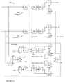
- FIG. 4 illustrates an example of a multichannel tape drive 400 having two, or in general multiple, master channels and multiple slave channels according to a third, alternative embodiment of the present disclosure.
- Multichannel tape drive 400 is similar as multichannel tape drive 300 with one exception: it includes more than one master channel (e.g., master calibration channel 1 and master calibration channel 2 ), each master channel additionally includes data storage units 222 E and 222 F.
- data storage units 222 E and 222 F may be Random Access Memory (RAM).
- data storage units 222 E and 222 F may be situated between a multiplexer 221 E and a head signal linearizer 111 E or 111 F.
- input signals x 0 to x n-1 to slave channels 0 to n ⁇ 1 may first be stored in data storage 222 E as directed by a selector 423 E.
- Input signals x 0 to x n-1 to slave channels 0 to n ⁇ 1 may then be stored in data storage 222 F as directed by selector 423 E, while the stored information in data storage 222 E is processed by one master channel.
- input signals x 0 to x n-1 to slave channels 0 to n ⁇ 1 may again be stored in data storage 222 E as directed by selector 423 E, while the stored information in data storage 222 F is processed by another master channel, the procedure continuing in alternation.
- each master channel may process data at the rate of the individual slave channels without introducing data loss.
- the stored data may be removed from data storage units 222 E and 222 F by each master channel continuously, but at a rate slower than the rate that data are stored (i.e., written) into data storage units 222 E and 222 F.
- the stored data may be removed from data storage units 222 E and 222 F by each master channel at a rate that is approximately half of the rate that are stored into data storage units 222 E and 222 F.
- the present disclosure may require that the master channel introduces less complexity than it relieves (i.e., by removing the adaptive filters from the individual slave channels). Therefore, in particular embodiments, the number of slave channels, n, served by a master channel may have a minimum value for each design. The minimum value may depend on the number and size of the adaptive filters in the individual channels and may be determined by analysis. In particular embodiments, if the adaptive portions of the filters in each channel are known to occupy a fraction, 1/k, of the total channel area, then it may be shown that complexity is reduced whenever n>k. Similarly in the case of m multiple master channels complexity is reduced whenever n>mk.
- the components included in a master channel or a slave channel may be implemented as software, firmware, hardware, or a combination thereof.
- the adaptive equalizer and the adaptive linear predictor included in the master channel, the fixed equalizer and the fixed linear predictor included in each slave channel, and the timing recovery module included in the master channel and each slave channel may each be implemented as Integrated Circuits (ICs) using suitable designs such as, for example, Field-Programmable Gate Array (FPGA), Application-Specific Instruction-Set Processor (ASIP), ASIC, or Complex Programmable Logic Device (CPLD).
- FPGA Field-Programmable Gate Array
- ASIP Application-Specific Instruction-Set Processor
- ASIC Application-Specific Instruction-Set Processor
- CPLD Complex Programmable Logic Device
- Functional logic may be embedded in such ICs so that each component may perform the necessary operations (e.g., the adaptive filter of the master channel may be programmed to determine the filter coefficients for the slave channels, and the non-adaptive filter of each slave channel may be programmed to filter the input signal to the slave channel using the predetermined filter coefficients).
- each component may perform the necessary operations (e.g., the adaptive filter of the master channel may be programmed to determine the filter coefficients for the slave channels, and the non-adaptive filter of each slave channel may be programmed to filter the input signal to the slave channel using the predetermined filter coefficients).
- the master channel and the slave channels illustrated in FIGS. 2 , 3 , and 4 may include different components in different implementations.
- the master channel and each of the slave channels may or may not include a head signal linearizer.
- the above description describe particular embodiments with reference to different functional units and processors. However, it will be apparent that any suitable distribution of functionality between different functional units, processors, or domains may be used without detracting from the disclosure. For example, functionality illustrated to be performed by separate processors or controllers may be performed by the same processor or controller.
- references to specific functional units are only to be seen as references to suitable means for providing the described functionality, rather than indicative of a strict logical or physical structure or organization.
- references to suitable means for providing the described functionality rather than indicative of a strict logical or physical structure or organization.
- the present disclosure describes or illustrates particular operations as occurring in a particular order, the present disclosure contemplates any suitable operations occurring in any suitable order. Moreover, the present disclosure contemplates any suitable operations being repeated one or more times in any suitable order. Although the present disclosure describes or illustrates particular operations as occurring in sequence, the present disclosure contemplates any suitable operations occurring at substantially the same time, where appropriate. Any suitable operation or sequence of operations described or illustrated herein may be interrupted, suspended, or otherwise controlled by another process, such as an operating system or kernel, where appropriate. The acts can operate in an operating system environment or as stand-alone routines occupying all or a substantial part of the system processing.
Abstract
Description
Claims (19)
Priority Applications (1)
| Application Number | Priority Date | Filing Date | Title |
|---|---|---|---|
| US12/695,293 US7961415B1 (en) | 2010-01-28 | 2010-01-28 | Master calibration channel for a multichannel tape drive |
Applications Claiming Priority (1)
| Application Number | Priority Date | Filing Date | Title |
|---|---|---|---|
| US12/695,293 US7961415B1 (en) | 2010-01-28 | 2010-01-28 | Master calibration channel for a multichannel tape drive |
Publications (1)
| Publication Number | Publication Date |
|---|---|
| US7961415B1 true US7961415B1 (en) | 2011-06-14 |
Family
ID=44121923
Family Applications (1)
| Application Number | Title | Priority Date | Filing Date |
|---|---|---|---|
| US12/695,293 Expired - Fee Related US7961415B1 (en) | 2010-01-28 | 2010-01-28 | Master calibration channel for a multichannel tape drive |
Country Status (1)
| Country | Link |
|---|---|
| US (1) | US7961415B1 (en) |
Cited By (3)
| Publication number | Priority date | Publication date | Assignee | Title |
|---|---|---|---|---|
| US9436591B1 (en) * | 2013-09-30 | 2016-09-06 | Emc Corporation | Out-of-band file transfers between a host and virtual tape server |
| US9548080B2 (en) * | 2015-06-18 | 2017-01-17 | International Business Machines Corporation | Time-varying filter for high-frequency reel disturbance rejection |
| US10263826B1 (en) | 2013-09-30 | 2019-04-16 | EMC IP Holding Company LLC | Method of initiating execution of mainframe jobs from a virtual tape server |
Citations (11)
| Publication number | Priority date | Publication date | Assignee | Title |
|---|---|---|---|---|
| US4956838A (en) * | 1988-03-15 | 1990-09-11 | Etat Francais Represente Par Le Ministre Des Postes, Telecommunications Et De L'espace (Centre National D'etudes Des Telecommunications) | Echo cancelling device with frequency sub-band filtering |
| US5491487A (en) * | 1991-05-30 | 1996-02-13 | The United States Of America As Represented By The Secretary Of The Navy | Slaved Gram Schmidt adaptive noise cancellation method and apparatus |
| US5555285A (en) * | 1995-03-30 | 1996-09-10 | Westell Incorporated | Multi-variate system having an intelligent telecommunications interface with automatic adaptive delay distortion equalization (and related method) |
| US6178248B1 (en) * | 1997-04-14 | 2001-01-23 | Andrea Electronics Corporation | Dual-processing interference cancelling system and method |
| US6556682B1 (en) * | 1997-04-16 | 2003-04-29 | France Telecom | Method for cancelling multi-channel acoustic echo and multi-channel acoustic echo canceller |
| US6909782B2 (en) * | 2000-09-08 | 2005-06-21 | Intel Corporation | Fast converging affine projection based echo canceller for sparse multi-path channels |
| US7167884B2 (en) * | 2002-04-22 | 2007-01-23 | The United States Of America As Represented By The Secretary Of The Navy | Multistage median cascaded canceller |
| US7426464B2 (en) * | 2004-07-15 | 2008-09-16 | Bitwave Pte Ltd. | Signal processing apparatus and method for reducing noise and interference in speech communication and speech recognition |
| US20100010811A1 (en) * | 2006-08-04 | 2010-01-14 | Panasonic Corporation | Stereo audio encoding device, stereo audio decoding device, and method thereof |
| US20100053444A1 (en) * | 2008-08-27 | 2010-03-04 | Ali Corporation | Signal processing circuit and signal processing method for removing co-channel interference |
| US7783478B2 (en) * | 2007-01-03 | 2010-08-24 | Alexander Goldin | Two stage frequency subband decomposition |
-
2010
- 2010-01-28 US US12/695,293 patent/US7961415B1/en not_active Expired - Fee Related
Patent Citations (12)
| Publication number | Priority date | Publication date | Assignee | Title |
|---|---|---|---|---|
| US4956838A (en) * | 1988-03-15 | 1990-09-11 | Etat Francais Represente Par Le Ministre Des Postes, Telecommunications Et De L'espace (Centre National D'etudes Des Telecommunications) | Echo cancelling device with frequency sub-band filtering |
| US5491487A (en) * | 1991-05-30 | 1996-02-13 | The United States Of America As Represented By The Secretary Of The Navy | Slaved Gram Schmidt adaptive noise cancellation method and apparatus |
| US5555285A (en) * | 1995-03-30 | 1996-09-10 | Westell Incorporated | Multi-variate system having an intelligent telecommunications interface with automatic adaptive delay distortion equalization (and related method) |
| US6178248B1 (en) * | 1997-04-14 | 2001-01-23 | Andrea Electronics Corporation | Dual-processing interference cancelling system and method |
| US6332028B1 (en) * | 1997-04-14 | 2001-12-18 | Andrea Electronics Corporation | Dual-processing interference cancelling system and method |
| US6556682B1 (en) * | 1997-04-16 | 2003-04-29 | France Telecom | Method for cancelling multi-channel acoustic echo and multi-channel acoustic echo canceller |
| US6909782B2 (en) * | 2000-09-08 | 2005-06-21 | Intel Corporation | Fast converging affine projection based echo canceller for sparse multi-path channels |
| US7167884B2 (en) * | 2002-04-22 | 2007-01-23 | The United States Of America As Represented By The Secretary Of The Navy | Multistage median cascaded canceller |
| US7426464B2 (en) * | 2004-07-15 | 2008-09-16 | Bitwave Pte Ltd. | Signal processing apparatus and method for reducing noise and interference in speech communication and speech recognition |
| US20100010811A1 (en) * | 2006-08-04 | 2010-01-14 | Panasonic Corporation | Stereo audio encoding device, stereo audio decoding device, and method thereof |
| US7783478B2 (en) * | 2007-01-03 | 2010-08-24 | Alexander Goldin | Two stage frequency subband decomposition |
| US20100053444A1 (en) * | 2008-08-27 | 2010-03-04 | Ali Corporation | Signal processing circuit and signal processing method for removing co-channel interference |
Cited By (3)
| Publication number | Priority date | Publication date | Assignee | Title |
|---|---|---|---|---|
| US9436591B1 (en) * | 2013-09-30 | 2016-09-06 | Emc Corporation | Out-of-band file transfers between a host and virtual tape server |
| US10263826B1 (en) | 2013-09-30 | 2019-04-16 | EMC IP Holding Company LLC | Method of initiating execution of mainframe jobs from a virtual tape server |
| US9548080B2 (en) * | 2015-06-18 | 2017-01-17 | International Business Machines Corporation | Time-varying filter for high-frequency reel disturbance rejection |
Similar Documents
| Publication | Publication Date | Title |
|---|---|---|
| CN109104200B (en) | Approximate parameter adaptation | |
| KR101489544B1 (en) | Systems and methods for adaptive target search | |
| US8295001B2 (en) | Systems and methods for low latency noise cancellation | |
| US8873182B2 (en) | Multi-path data processing system | |
| US20130322512A1 (en) | Receiver with four-slice decision feedback equalizer | |
| US8413020B2 (en) | Systems and methods for retimed virtual data processing | |
| JP3606813B2 (en) | Data reproducing apparatus and method for improving detection performance by adjusting a decision level used in a data detector | |
| US7821730B2 (en) | Systems and methods for compensating baseline wandering in perpendicular magnetic recording | |
| EP2587483A1 (en) | Hardware-based inter-track interference mitigation in magnetic recording systems with read channel storage of cancelation data | |
| US7961415B1 (en) | Master calibration channel for a multichannel tape drive | |
| US6381085B1 (en) | Zero forcing adaptive equalization in a disk drive read channel | |
| JPH1098395A (en) | Metric circuit for usage in viterbi detecter and its method | |
| US8631311B1 (en) | Data recovery using existing reconfigurable read channel hardware | |
| US9190104B2 (en) | Systems and methods for data retry using averaging process | |
| US10692527B1 (en) | Target parameter adaptation | |
| US8379339B2 (en) | Closely coupled vector sequencers for a read channel pipeline | |
| EP2741291A1 (en) | Systems and methods for old data inter-track interference compensation | |
| US20140082461A1 (en) | Systems and Methods for Detector Side Trapping Set Mitigation | |
| US9767842B2 (en) | Asynchronous asymmetry compensation for data read from a storage medium | |
| US8848308B2 (en) | Systems and methods for ADC sample based inter-track interference compensation | |
| US8773791B1 (en) | Systems and methods for X-sample based noise cancellation | |
| US8854756B1 (en) | Systems and methods for mitigating data interference in a contact signal | |
| US8837064B1 (en) | Systems and methods for quality based bit error rate prediction | |
| US8838660B2 (en) | Systems and methods for reducing filter sensitivities | |
| US8594254B2 (en) | Waveform interpolator architecture for accurate timing recovery based on up-sampling technique |
Legal Events
| Date | Code | Title | Description |
|---|---|---|---|
| AS | Assignment |
Owner name: QUANTUM CORPORATION, CALIFORNIA Free format text: ASSIGNMENT OF ASSIGNORS INTEREST;ASSIGNOR:FELLER, MARC;REEL/FRAME:023863/0862 Effective date: 20100127 |
|
| STCF | Information on status: patent grant |
Free format text: PATENTED CASE |
|
| AS | Assignment |
Owner name: WELLS FARGO CAPITAL FINANCE, LLC, AS AGENT, CALIFO Free format text: SECURITY AGREEMENT;ASSIGNOR:QUANTUM CORPORATION;REEL/FRAME:027967/0914 Effective date: 20120329 |
|
| FPAY | Fee payment |
Year of fee payment: 4 |
|
| AS | Assignment |
Owner name: TCW ASSET MANAGEMENT COMPANY LLC, AS AGENT, MASSACHUSETTS Free format text: SECURITY INTEREST;ASSIGNOR:QUANTUM CORPORATION;REEL/FRAME:040451/0183 Effective date: 20161021 Owner name: TCW ASSET MANAGEMENT COMPANY LLC, AS AGENT, MASSAC Free format text: SECURITY INTEREST;ASSIGNOR:QUANTUM CORPORATION;REEL/FRAME:040451/0183 Effective date: 20161021 |
|
| AS | Assignment |
Owner name: PNC BANK, NATIONAL ASSOCIATION, PENNSYLVANIA Free format text: SECURITY INTEREST;ASSIGNOR:QUANTUM CORPORATION;REEL/FRAME:040473/0378 Effective date: 20161021 Owner name: QUANTUM CORPORATION, CALIFORNIA Free format text: RELEASE BY SECURED PARTY;ASSIGNOR:WELLS FARGO CAPITAL FINANCE, LLC, AS AGENT;REEL/FRAME:040474/0079 Effective date: 20161021 |
|
| AS | Assignment |
Owner name: U.S. BANK NATIONAL ASSOCIATION, AS AGENT, OHIO Free format text: SECURITY INTEREST;ASSIGNORS:QUANTUM CORPORATION, AS GRANTOR;QUANTUM LTO HOLDINGS, LLC, AS GRANTOR;REEL/FRAME:049153/0518 Effective date: 20181227 Owner name: QUANTUM CORPORATION, CALIFORNIA Free format text: RELEASE BY SECURED PARTY;ASSIGNOR:TCW ASSET MANAGEMENT COMPANY LLC, AS AGENT;REEL/FRAME:047988/0642 Effective date: 20181227 |
|
| AS | Assignment |
Owner name: PNC BANK, NATIONAL ASSOCIATION, PENNSYLVANIA Free format text: SECURITY INTEREST;ASSIGNOR:QUANTUM CORPORATION;REEL/FRAME:048029/0525 Effective date: 20181227 |
|
| FEPP | Fee payment procedure |
Free format text: MAINTENANCE FEE REMINDER MAILED (ORIGINAL EVENT CODE: REM.); ENTITY STATUS OF PATENT OWNER: LARGE ENTITY |
|
| LAPS | Lapse for failure to pay maintenance fees |
Free format text: PATENT EXPIRED FOR FAILURE TO PAY MAINTENANCE FEES (ORIGINAL EVENT CODE: EXP.); ENTITY STATUS OF PATENT OWNER: LARGE ENTITY |
|
| STCH | Information on status: patent discontinuation |
Free format text: PATENT EXPIRED DUE TO NONPAYMENT OF MAINTENANCE FEES UNDER 37 CFR 1.362 |
|
| FP | Lapsed due to failure to pay maintenance fee |
Effective date: 20190614 |
|
| AS | Assignment |
Owner name: QUANTUM CORPORATION, CALIFORNIA Free format text: RELEASE BY SECURED PARTY;ASSIGNOR:U.S. BANK NATIONAL ASSOCIATION;REEL/FRAME:057142/0252 Effective date: 20210805 Owner name: QUANTUM LTO HOLDINGS, LLC, CALIFORNIA Free format text: RELEASE BY SECURED PARTY;ASSIGNOR:U.S. BANK NATIONAL ASSOCIATION;REEL/FRAME:057142/0252 Effective date: 20210805 |